

Page 1
KDD-PSU
POWER SUPPLY UNIT
Instruction Manual
071829803
FEBRUARY 2005
Page 2

KDD-PSU Power Supply Unit
Contacting Grass Valley
Region Voice Fax Address Web Site
North America (800) 547-8949
Support: 530-478-4148
Pacific Operations +852-2585-6688
Support: +852-2585-6579
U.K., Asia, Middle East +44 1753 218 777 +44 1753 218 757
France +33 1 45 29 73 00
Germany, Europe +49 6150 104 782 +49 6150 104 223
Copyright © Thomson Broadcast and Media Solutions All rights reserved.
Grass Valley Web Site
The www.thomsongrassvalley.com web site offers the following:
Sales: (530) 478-3347
Support: (530) 478-3181
+852-2802-2996
Grass Valley
P.O. Box 599000
Nevada City,
CA 95959-7900
USA
www.thomsongrassvalley.com
Online User Documentation — Current versions of product catalogs, brochures, data sheets, ordering
guides, planning guides, manuals, and release notes in .pdf format can be downloaded.
FAQ Database — Solutions to problems and troubleshooting efforts can be found by searching our
Frequently Asked Questions (FAQ) database.
Software Downloads — Software updates, drivers, and patches can be downloaded.
2 Instruction Manual
Page 3

KDD-PSU Power Supply Unit
Table of Contents
1 Preface..............................................................................................................................................................7
1.1 About This Manual.....................................................................................................................................7
2 Regulatory Notices............................................................................................................................................9
2.1 Certifications and Compliances .................................................................................................................9
2.1.1 FCC Emission Control........................................................................................................................9
2.1.2 Canadian EMC Notice of Compliance................................................................................................9
2.1.3 FCC Emission Limits ..........................................................................................................................9
2.1.4 Certification and Compliance............................................................................................................10
3 Safety Summary..............................................................................................................................................13
3.1 Safety Terms and Symbols......................................................................................................................13
3.1.1 Terms in This Manual.......................................................................................................................13
3.1.2 Terms on the Product.......................................................................................................................13
3.1.3 Symbols on the Product....................................................................................................................14
3.2 Warnings..................................................................................................................................................15
3.3 Cautions...................................................................................................................................................16
4 Technical Specification....................................................................................................................................17
4.1 Power Supply...........................................................................................................................................17
4.2 Environmental Data .................................................................................................................................17
4.3 Mechanical Data......................................................................................................................................17
5 System Overview ............................................................................................................................................19
5.1 Introduction ..............................................................................................................................................19
5.2 DC Power Applications............................................................................................................................20
5.2.1 Standard Application for Redundancy..............................................................................................20
5.2.2 Control Panel Supply........................................................................................................................21
5.2.3 Multiple DC Power Supply................................................................................................................22
6 Installation.......................................................................................................................................................25
6.1 Pre-Installation Procedures......................................................................................................................25
6.1.1 System Survey..................................................................................................................................25
6.1.2 Line Voltage......................................................................................................................................25
6.1.3 Safety Requirements........................................................................................................................25
6.1.4 Installation Tasks..............................................................................................................................26
6.2 Mounting the Power Supply Unit..............................................................................................................27
6.2.1 General Rack Mounting Instructions ................................................................................................27
6.2.2 Rack Mounting Procedure................................................................................................................28
6.3 Rear Connectors......................................................................................................................................29
6.4 Pin Assignments ......................................................................................................................................31
6.4.1 48V DC Power Out...........................................................................................................................31
Instruction Manual 3
Page 4

KDD-PSU Power Supply Unit
7 Service Instructions........................................................................................................................................ 33
7.1 General.................................................................................................................................................... 33
7.2 Status LEDs ............................................................................................................................................ 33
7.3 Fuses....................................................................................................................................................... 33
7.3.1 Main Fuses....................................................................................................................................... 33
7.3.2 Internal Fuses on Board RY3781.....................................................................................................33
7.4 Fan Exchange .........................................................................................................................................34
Table of Figures
Figure 1 Redundant Power Supply for one Mainframe and one Control Panel.............................................. 20
Figure 2 Power Supply for Control Panel only ................................................................................................ 21
Figure 3 Separate Power Supply for Control Panel and Mainframe KayakDD-1............................................ 22
Figure 4 Separate Power Supply for Control Panel and Mainframe KayakDD-2............................................ 23
Figure 5 KDD-PSU Power Supply Unit with Mounting Accessories................................................................ 28
Figure 6 KDD-PSU Rear Connectors 1........................................................................................................... 29
Figure 7 KDD-PSU Rear Connectors 2........................................................................................................... 30
Figure 8 Mounting Overview............................................................................................................................35
4 Instruction Manual
Page 5
KDD-PSU Power Supply Unit
Instruction Manual 5
Page 6

KDD-PSU Power Supply Unit
6 Instruction Manual
Page 7

1 Preface
1.1 About This Manual
This KDD-PSU Manual provides installation, configuration, and service information for
the External Power Supply for the Thomson Grass Valley KayakDD Digital Production
Switchers. This manual is designed for technical personnel resp onsible for installing
and maintaining KayakDD-1 or KayakDD-2 systems.
KDD-PSU Power Supply Unit
Instruction Manual 7
Page 8

KDD-PSU Power Supply Unit
8 Instruction Manual
Page 9

KDD-PSU Power Supply Unit
2 Regulatory Notices
2.1 Certifications and Compliances
2.1.1 FCC Emission Control
This equipment has been tested and found to comply with the limits for a Class B
digital device, pursuant to Part 15 of the FCC Rules. These limits are designed to
provide reasonable protection against harmful interference when the equipment is
operated in a commercial environment. This equipment generates, uses, and can
radiate radio frequency energy and, if not installed and used in accordance with the
instruction manual, may cause harmful interference to radio communications.
Operation of this equipment in a residential area is likely to cause harmful interference
in which case the user will be required to correct the interference at his own expense.
Changes or modifications not expressly approved by Thomson Grass Valley can affect
emission compliance and could void the user’s authority to operate this equipment.
2.1.2 Canadian EMC Notice of Compliance
This digital apparatus does not exceed the Class B limits for radio noise emissions
from digital apparatus set out in the Radio Interference Regulations of the Canadian
Department of Communications.
Le présent appareil numérique n’emet pas de bruits radioélectriques dépassant hors
des limites applicables aux appareils numériques de la classe B préscrites dans le
Règlement sur le brouillage radioélectrique édicte par le ministère des
Communications du Canada.
2.1.3 FCC Emission Limits
This device complies with Part 15 of the FCC 47 Rules. Operation is subject to the
following two conditions: (1) This device may no cause harmful interference, and (2)
this device must accept any interference received, including interference that may
cause undesirable operation.
Instruction Manual 9
Page 10

KDD-PSU Power Supply Unit
2.1.4 Certification and Compliance
This product has been evaluated for Electromagnetic Compatibility under the E N
55103-1/2 standards for Emissions and Immunity and meets the requirement s for
E1/E2 environment.
This product complies with Class B. In a domestic environment this product may cause
radio interference in which case the user may be required to take adequate measures.
This product has been evaluated and meets the following Safety Certification
Standards:
Category Standard Designed/tested for compliance with
Safety ANSI / UL60950
IEC 60950
73/23/EEC Low Voltage Directive
CAN/CSA C22.2,
No. 60950-00
Europe:
EN 60950
Safety of Information Technology Equipment,
including Electrical Business Equipment.
Safety of Information Technology Equipment,
including Electrical Business Equipment
Safety of Information Technology Equipment,
including Electrical Business Equipment.
Safety of Information Technology Equipment,
including Electrical Business Equipment.
10 Instruction Manual
Page 11

KDD-PSU Power Supply Unit
Category Standard Designed/tested for compliance with
EMI
EMC Directive
89/336/EEC via
Audio, Video and Entertainment Lighting
Control for the European Community.
EN 55103-1 and 2
EN 55103-1
standards
Electromagnetic compatibility.
Product family standard for audio, video, audiovisual and entertainment lighting control
apparatus for professional use.
Part 1 Emissions, Environment E1/E2
EN 55022: Class B Radiated and Conducted
Emissions
EN 61000-3-2: Power Line Harmonic
Emissions, Radiated Magnetic Field Emissions,
Peak Inrush Current
EN55103-2
standards
Electromagnetic compatibility--Product family
standard for audio, video, audio-visual and
entertainment lighting control apparatus for
professional use.
Part 2 Immunity, Environment E1/E2
EN 50082-1: Immunity
EN 61000-4-2:
Electrostatic Discharge “ESD” Immunity
EN 61000-4-3:
Radiated RF Electromagnetic Field Immunity
EN 61000-4-4:
Electrical Fast Transient/Burst “EFT” Immunity
EN 61000-4-5: Surge Immunity
EN 61000-4-6: Conducted RF Immunity
EN 61000-4-11: Voltage Dips, Short
Interruptions and Voltage Variations
Annex A - Radiated Magnetic Field Immunity
Note: This only applies to assemblies sensitive
to magnetic fields
US FCC Class B CISPR Pub. 22 (1985)
Canada FCC
Industry Canada
Australia &
New Zealand:
AS/NZS 3548
Instruction Manual 11
Page 12

KDD-PSU Power Supply Unit
12 Instruction Manual
Page 13

3 Safety Summary
Read and follow the important safety information below, noting especially those
instructions related to risk of fire, electric shock or injury to persons. Additional specific
warnings not listed here may be found throughout the manual.
WARNING!
Any instructions in this manual that require opening the equipment cover or
enclosure are for use by qualified service personnel only. To reduce the
risk of electric shock, do not perform any servicing other than that contained in
the operating instructions unless you are qualified to do so.
3.1 Safety Terms and Symbols
3.1.1 Terms in This Manual
Safety-related statements may appear in this manual in the following form:
WARNING!
Warning statements identify conditions or practices that may result in personal
injury or loss of life.
CAUTION!
Caution statements identify conditions or practices that may result in damage
to equipment or other property, or which may cause equipment crucial to
your business environment to become temporarily non-operational.
KDD-PSU Power Supply Unit
3.1.2 Terms on the Product
The following terms may appear on the product:
DANGER!
A personal injury hazard is immediately accessible as you read
the marking.
WARNING!
A personal injury hazard exists but is not immediately accessible
as you read the marking.
CAUTION!
A hazard to property, product, and other equipment is present.
Instruction Manual 13
Page 14

KDD-PSU Power Supply Unit
3.1.3 Symbols on the Product
The following symbols may appear on the product:
Indicates that dangerous high voltage is present within the equipment enclosure that
may be of sufficient magnitude to
constitute a risk of electric shock.
Indicates that user, operator or service technician should refer to product manual(s) for
important operating, maintenance, or service instructions.
This is a prompt to note fuse rating when replacing fuse(s).
The fuse referenced in the text must be replaced with one having the ratings indicated.
Identifies a protective grounding terminal which must be connected to earth ground
prior to making any other equipment connections.
Identifies an internal Protective Bounding Conductor (PBC) terminal proper earthing of
metal parts auf the unit (EN 60950 / 1.1.13.9).
Indicates that static sensitive components are present which
may be damaged by electrostatic discharge. Use anti-static
procedures, equipment and surfaces during servicing.
14 Instruction Manual
Page 15

3.2 Warnings
The following warning statements identify conditions or practices that can result in
personal injury or loss of life.
WARNING — To reduce the risk of electrical shock, do not remove cover or back. No
user-serviceable parts inside. Refer to qualified service personnel.
• Dangerous voltage or current may be present — Disconnect power and remove
battery (if applicable) before removing protective panels, soldering, or replacing
components.
• Do not service alone — Do not internally service this product unless another
person capable of rendering first aid and resuscitation is present.
• Remove jewelry — Prior to servicing, remove jewelry such as rings, watches, and
other metallic objects.
• Avoid exposed circuitry — Do not touch exposed connections, components or
circuitry when power is present.
• Use proper power cord — Use only the power cord supplied or specified for this
product.
• Ground product — Connect the protective grounding conductor of the power cord
to earth ground.
• Operate only with covers and enclosure panels in place — Do not operate this
product when covers or enclosure panels are removed.
• Use correct fuse — Use only the fuse type and rating specified for this product.
• Use only in dry environment — Do not operate in wet or damp conditions.
• Use only in non-explosive environment — Do not operate this product in an
explosive atmosphere.
• High leakage current may be present — Earth connection of product is essential
before connecting power.
• Dual power supplies may be present — Be certain to plug each power supply
cord into a separate branch circuit employing a separate service ground.
Disconnect both power supply cords prior to servicing.
• Double pole neutral fusing — Disconnect mains power prior to servicing.
• Use proper lift points — Do not use door latches to lift or move equipment.
• Avoid mechanical hazards — Allow all rotating devices to come to a stop before
servicing.
KDD-PSU Power Supply Unit
Instruction Manual 15
Page 16

KDD-PSU Power Supply Unit
3.3 Cautions
The following caution statements identify conditions or practices that can
result in damage to equipment or other property:
• Use correct power source — Do not operate this product from a power source
that applies more than the voltage specified for the product.
• Use correct voltage setting — If this product lacks auto-ranging power supplies,
before applying power ensure that the each power supply is set to match the
power source.
• Provide proper ventilation — To prevent product overheating, provide equipment
ventilation in accordance with installation instructions.
• Use anti-static procedures — Static sensitive components are present which
may be damaged by electrostatic discharge. Use anti-static procedures, equipment
and surfaces during servicing.
• Do not operate with suspected equipment failure — If you suspect product
damage or equipment failure, have the equipment inspected by qualified service
personnel.
• Ensure mains disconnect — If mains switch is not provided, the power cord(s) of
this equipment provide the means of disconnection. The socket outlet must be
installed near the equipment and must be easily accessible. Verify that all mains
power is disconnected before installing or removing power supplies and/or options.
• Route cable properly — Route power cords and other cables so that they are n ot
likely to be damaged. Properly support heavy cable bundles to avoid connector
damage.
• Use correct power supply cords — Power cords for this equipment, if provided,
meet all North American electrical codes. Operation of this equipment at voltages
exceeding 130 VAC requires power supply cords which comply with NEMA
configurations. International power cords, if provided, have the approval of the
country of use.
• Use correct replacement battery — This product may contain batteries. To
reduce the risk of explosion, check polarity and replace only with the same or
equivalent type recommended by manufacturer. Dispose of used batteries
according to the manufacturer’s instructions.
• Troubleshoot only to board level — Circuit boards in this product are densely
populated with surface mount technology (SMT) components and application
specific integrated circuits (ASICs). As a result, circuit board repair at the
component level is very difficult in the field, if not impossible. For warranty
compliance, do not troubleshoot systems beyond the board level.
16 Instruction Manual
Page 17

KDD-PSU Power Supply Unit
4 Technical Specification
4.1 Power Supply
Line voltage 100V-240V AC +/-10%,
power factor corrected
Line frequency 50/60Hz +/- 5%
Power consumption max. 375W
Leakage current < 2 mA at 250V AC
DC-OUT 2x 48V DC, total 6A max
EXT BATT IN 12V … 24V, 0.5A
RAM Recorder
buffer voltage: 7V DC, max 300mA. (Only with ext. battery input or AC In)
4.2 Environmental Data
Storage temperature -20°C to +70°C (-4°F to 158°F)
Operating temperature +5°C to +40°C (41°F to 104°F)
Relative humidity ≤ 95% non-condensing
Electromagnetic
environment E2 (according to EN55103-1, -2)
4.3 Mechanical Data
Height 1RU 44 mm (1.73 in ch)
Width 482 mm (19 inch)
Depth 240 mm (9.45 inch)
Weight 2.8 kg (6.2 lb)
Instruction Manual 17
Page 18

KDD-PSU Power Supply Unit
18 Instruction Manual
Page 19

5 System Overview
5.1 Introduction
KDD-PSU Power Supply Unit
Wide range AC power supply providing redundant power for KayakDD production
switcher. Power output is sufficient for two KayakDD-1 or one KayakDD-2 system.
External battery voltage can be connected in order to provide uninterrupted buffer
voltage for RAM Recorder option.
The package contents:
• 1pc KDD-PSU External Power Supply Unit
• 1pc AC power cord
• Rack mount accessories
• Instruction Manual
There are two lengths of cable to the KayakDD mainframe available:
• 5m (KDD-PS U-CABLE5)
• 20m (KDD-PSU-CABLE20)
To connect a KayakDD Control Panel to the second DC output the following cables
can also be used:
• 20m (KDD-PSU-CABLE20)
• 50m (DCP WR -50)
• 100m (DCP WR-100)
NOTE!
In order to ensure the RAM Recorder buffer voltage, the cable length is
limited to 20m. The standard KayakDD DC cables are not suitable for buffer
voltage supply!
Instruction Manual 19
Page 20

KDD-PSU Power Supply Unit
5.2 DC Power Applications
Note! The DC cables in the diagrams below are not included!
5.2.1 Standard Application for Redundancy
AC1
Redundant Power Supply Unit
KDD-PSU
Ext. Battery In
12-24V
Other cable available:
Cable 20m (with RAM buffering)
Cable 20m (w/o RAM buffering)
Cable 50m (w/o RAM buffering)
Cable 100m (w/o RAM buffering)
AC2
Mainframe
KayakDD-1
KayakDD-2KayakDD-2
20m cable
5m cable
Other cables
available:
Cable 50m
Cable 100m
KayakDD-2
KayakDD-1
Figure 1 Redundant Power Supply for one Mainframe and one Control Panel
20 Instruction Manual
Page 21

5.2.2 Control Panel Supply
KDD-PSU Power Supply Unit
AC2
Mainframe
KayakDD-1
KayakDD-2KayakDD-2
Distance more than 100m
Control Panel
AC1
Panel Power Supply Unit
KDD-PSU
5m cable
Other cables available:
Cable 20m
Cable 50m
Cable 100m
Figure 2 Power Supply for Control Panel only
KayakDD-1
or
KayakDD-2
Instruction Manual 21
Page 22

KDD-PSU Power Supply Unit
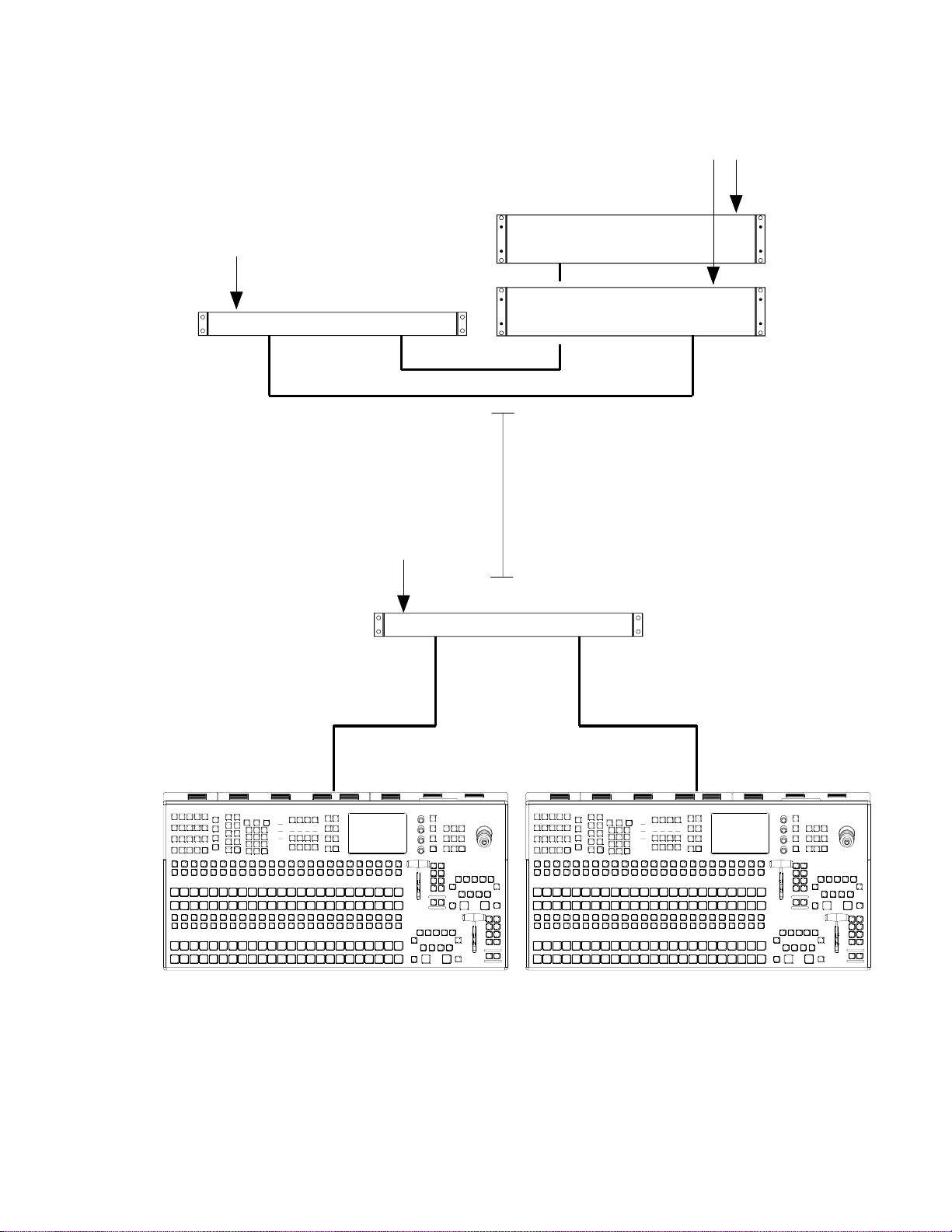
5.2.3 Multiple DC Power Supply
2x AC2
Mainframe 1
KayakDD-1
AC1
Redundant Power Supply Unit
KDD-PSU
NOTE!
Redundancy is ensured in case of a
failure in one of the two internal power
supply units (n+1 Redundancy).
AC3
5m cable 5m cable
Mainframe 2
KayakDD-1
5m cable
5m cable
Other cable available:
Cable 5m (with RAM buffering)
Cable 20m (with RAM buffering)
Cable 20m (w/o RAM buffering)
Cable 50m (w/o RAM buffering)
Cable 100m (w/o RAM buffering)
Distance more than 100m
Panel Power Supply Unit
KDD-PSU
Control Panel 1
Control Panel 2
Figure 3 Separate Power Supply for Control Panel and Mainframe KayakDD-1
22 Instruction Manual
Page 23
Mainframe 1
KayakDD-2
KDD-PSU Power Supply Unit
2x AC2
AC1
Redundant Power Supply Unit
KDD-PSU
NOTE!
Redundancy is ensured in case of a
failure in one of the two internal power
supply units (n+1 Redundancy).
AC3
5m cable 5m cable
Mainframe 2
KayakDD-2
5m cable
5m cable
Other cable available:
Cable 5m (with RAM buffering)
Cable 20m (with RAM buffering)
Cable 20m (w/o RAM buffering)
Cable 50m (w/o RAM buffering)
Cable 100m (w/o RAM buffering)
Distance more than 100m
Panel Power Supply Unit
KDD-PSU
Control Panel 1
Control Panel 2
Figure 4 Separate Power Supply for Control Panel and Mainframe KayakDD-2
Instruction Manual 23
Page 24

KDD-PSU Power Supply Unit
24 Instruction Manual
Page 25

6 Installation
This section describes the installation and setup of KDD-PSU Power Supply Unit.
6.1 Pre-Installation Procedures
Before you physically install the KDD-PSU Power Supply Unit, familiarize yourself with
the tools required, physical specifications, and safety and power requirements covered
in this section.
6.1.1 System Survey
Check all parts received against the packing list enclosed with your shipme nt, and
examine the equipment for any shipping damage. Immediately report any missing or
damaged items to the carrier and to your Thomson Grass Valley Service
Representative.
KDD-PSU Power Supply Unit
6.1.2 Line Voltage
KDD-PSU components utilize wide-ranging power supplies whi ch accommodate 100 240V. No switch settings are required, nor are any possible.
6.1.3 Safety Requirements
To prevent injury or equipment damage, read, understand, and follow all installation
safety precautions.
WARNING!
Electrical potential is still applied to some internal components even when power to the
frame is off. To prevent electrical shock when working on this equipment, disconnect
the AC line cords from the AC source before working on any internal components.
Residual voltage may be present immediately after unplugging the system; wait thirty
seconds to allow capacitors to discharge before working on the system.
Instruction Manual 25
Page 26

KDD-PSU Power Supply Unit
6.1.4 Installation Tasks
After completing the Pre-Installation procedures, the recommended installation
tasks given in this section are:
1. Unpack the equipment,
2. Install the KDD-PSU Power Supply Unit
3. Connect all cables between KayakDD devices,
4. Connect the power cables.
Power up and configuration is covered in detail in the next sections of this manual.
26 Instruction Manual
Page 27

6.2 Mounting the Power Supply Unit
6.2.1 General Rack Mounting Instructions
• The maximum ambient temperature for this unit is 40°C (104°F).
• Installing the unit in a closed or multi-unit rack assembly, together with other units
could increase the maximum ambient for this unit.
• If the unit is installed in a rack, no ventilation openings should be blocked or
otherwise covered. Ensure a sufficient amount of airflow. Airflow through KayakDD
(front view) is from the left side of the frame to the right side of the frame.
• Mounting of the unit in the rack should be such that a hazardous condition is not
achieved due to uneven mechanical loading.
• When connecting the unit to the supply circuit be sure that the supply circuit of the
rack is not overloaded. For ratings see chapter Technical Specifications.
• The unit must be grounded to a good earth ground using a wire as specified by the
local electrical code. This wire is attached to the protective earth connector on the
rear.
• When connecting the unit in a closed or multi-unit rack assembly together with
other units be sure that the summation of the touch (leakage) currents for each
power supply circuit is not higher than 3.5 mA . In this case the rack must be
permanently connected with an earth terminal. Earth connection is essential before
connecting supply voltage! For details see chapter Technical Specifications.
The Power Supply Unit frame has to be mounted in a rack using the delivered
accessories and screws.
KDD-PSU Power Supply Unit
Instruction Manual 27
Page 28
KDD-PSU Power Supply Unit
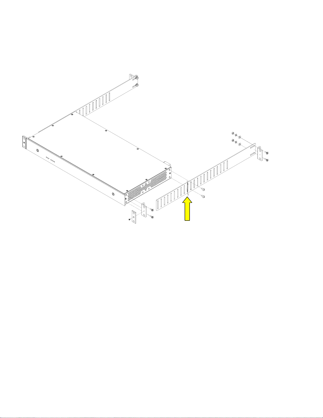
6.2.2 Rack Mounting Procedure
Figure 5 KDD-PSU Power Supply Unit with Mounting Accessories
Cut fastening metal so that
the ventilation openings are
not covered!
28 Instruction Manual
Page 29

6.3 Rear Connectors
KDD-PSU Power Supply Unit
Figure 6 KDD-PSU Rear Connectors 1
Jack Designation Note
J1 AC POWER IN
AC POWER IN
Mains connector (IEC-320, CEE-22) for power supply.
Operating Voltage: 100V-240V AC +/-10% wide-
range
Caution!
Double-pole or neutral fusing.
After operation of the protective device, parts of
the equipment that remain under voltage might
represent a hazard during servicing.
Caution!
For continued protection against risk of fire,
replace only with same type and rating of fuse!
2x 8A /T H 250V
Power switch
Instruction Manual 29
Page 30

KDD-PSU Power Supply Unit
Figure 7 KDD-PSU Rear Connectors 2
Jack Designation Note
J2 EXT. BATT IN
12V ... 24V DC
Terminal strip for connection to external battery for
buffering the RAM-Recorder data
J3 12V DC OUT
J4
DC POWER
J5
For future use!
Two output connectors for DC Power Supply.
(High current D-Sub, male).
Output voltage: 48V/ total 6A max
Earth Terminal
Earth terminal for grounding.
30 Instruction Manual
Page 31

6.4 Pin Assignments
6.4.1 48V DC Power Out
Socket Pin Signal
D-Sub Female
Pin 1Pin 2
Pin A2
Pin A1
Pin 3Pin 5
KDD-PSU Power Supply Unit
A1 48 V (+)
A2
1 GND
2 Return Sense
3 +7V (RAM Recorder)
4 -
5 Future use
48 V (−)
Instruction Manual 31
Page 32

KDD-PSU Power Supply Unit
32 Instruction Manual
Page 33

7 Service Instructions
7.1 General
WARNING — To reduce the risk of electrical shock, do not remove cover or back.
No user-serviceable parts inside. Refer to qualified service personnel.
7.2 Status LEDs
The status LEDs on the front of the KDD-PSU shows the state of the external and
internal voltages and the operating state of the internal fans:
AC On = AC Power OK
Ext.Batt On = External battery voltage is OK
Fans On = Both internal fans are OK
Off = One or both internal fans don’t run
48V-1 On = 48 V DC output 1 is OK
48V-2 On = 48 V DC output 2 is OK
12V On = 12V DC power supply for external Hub is OK (for future use)
7V On = 7V DC power for RAM Recorder buffering is OK
KDD-PSU Power Supply Unit
7.3 Fuses
• Double pole neutral fusing — Disconnect mains power prior to servicing.
• Use correct fuse — Use only the fuse type and rating specified for this product.
7.3.1 Main Fuses
Fuse type: 2x T 8A / H 250V
Manufacturer: WICKMANN 181, SCHURTER SPT 0001.2513
Order no.: 003 117 300 214
7.3.2 Internal Fuses on Board RY3781
T1, T2 F 7A / 250 V
Manufacturer: LITTLEFUSE 312007 or SCHURTER FSF 0034.5143
Order no.: 003 117 301 010
Instruction Manual 33
Page 34

KDD-PSU Power Supply Unit
7.4 Fan Exchange
The exchange of the fan can be carried out as follows:
• Demount the upper cover sheet
• Unplug the fan connection cable
• Pull the fan upwards. The fan in not fastened with screws!
• Insert the new fan in the same way.
• Do no damag e the connection cable when inserting the fan.
• Plug the fan connection cable
• Mount the upper cover sheet
to prevent bearing damage
do not touch the rotor !
34 Instruction Manual
Page 35

KDD-PSU Power Supply Unit
I
N
O
T
U
A
C
Figure 8 Mounting Overview
Instruction Manual 35
Page 36

KDD-PSU Power Supply Unit
36 Instruction Manual
 Loading...