

Page 1
K2 Dyno
Controller
User Manual
Software Version 1.6
071-8752-01
April 2010
Page 2
Affiliate with the N.V. KEMA in The Netherlands
CERTIFICATE
Certificate Number: 510040.001
The Quality System of:
Thomson Inc, and its worLdwide Grass Valley division affiliates DBA
GRASS VALLEY
Headquarters
400 Providence Mine Rd
Nevada City, CA 95959
United States
15655 SW Greystone Ct.
Beaverton, OR 97006
United States
10 Presidential Way
Suite 300
Woburn, MA 01801
United States
Kapittelweg 10
4827 HG Breda
The Nederlands
7140 Baymeadows Way
Ste 101
Jacksonville, FL 32256
United States
2300 So. Decker Lake Blvd.
Salt Lake City, UT 84119
United States
Rue du Clos Courtel
CS 31719
35517 Cesson-Sevigné Cedex
France
1 rue de l’Hautil
Z.I. des Boutries BP 150
78702 Conflans-Sainte
Honorine Cedex
France
Technopole Brest-Iroise
Site de la Pointe du Diable
CS 73808
29238 Brest Cedex 3
France
40 Rue de Bray
2 Rue des Landelles
35510 Cesson Sevigné
France
Spinnereistrasse 5
CH-5300 Turgi
Switzerland
Brunnenweg 9
D-64331 Weiterstadt
Germany
Carl-Benz-Strasse 6-8
67105 Schifferstadt
Germany
Including its implementation, meets the requirements of the standard:
ISO 9001:2008
Scope:
The design, manufacture and support of video and audio hardware and software products and
related systems
.
This Certificate is valid until: June 14, 2012
This Certificate is valid as of: June 14, 2009
Certified for the first time: June 14, 2000
H. Pierre Sallé
President
KEMA-Registered Quality
The method of operation for quality certification is defined in the KEMA General Terms
And Conditions For Quality And Environmental Management Systems Certifications.
Integral publication of this certificate is allowed.
KEMA-Registered Quality, Inc.
4377 County Line Road
Chalfont, PA 18914
Ph: (215)997-4519
Fax: (215)997-3809
CRT 001 073004
Accredited By:
ANAB
Page 3

K2 Dyno
Controller
User Manual
Software Version 1.6
071-8752-01
April 2010
Page 4
Copyright Copyright © Grass Valley, Inc. All rights reserved. Printed in the United States of America.
Portions of software © 2000 – 2010, Microsoft Corporation. All rights reserved. This document
may not be copied in whole or in part, or otherwise reproduced except as specifically permitted
under U.S. copyright law, without the prior written consent of Grass Valley, Inc., P.O. Box
59900, Nevada City, California 95959-7900. This product may be covered by one or more U.S.
and foreign patents.
Disclaimer Product options and specifications subject to change without notice. The information in this
manual is furnished for informational use only, is subject to change without notice, and should
not be construed as a commitment by Grass Valley, Inc. Grass Valley, Inc. assumes no
responsibility or liability for any errors or inacc uracies that may appear in this publication.
U.S. Government
Restricted Rights
Legend
Trademarks and
Logos
Revision Status
Use, duplication, or disclosure by the United States Government is subject to restrictions as set
forth in subparagraph (c)(1)(ii) of the Rights in Technical Data and Computer Software clause
at DFARS 252.277-7013 or in subparagraph c(1) and (2) of the Commercial Computer
Software Restricted Rights clause at FAR 52.227-19, as applicable. Manufacturer is Grass
Valley, Inc., P.O. Box 59900, Nevada City, California 95959-7900 U.S.A.
Grass Valley, K2, Aurora, Summit, Dyno, Solo, Infinity, Turbo, Profile, Profile XP, NetCentral,
NewsBrowse, NewsEdit, NewsQ, NewsShare, Ne wsQ Pro, and Media Manager are either
registered trademarks or trademarks of Grass Valley, Inc. in the United States and/or other
countries. Grass Valley, Inc. products are covered by U.S. and foreign patents, issued and
pending. Additional information regarding Grass Valley, Inc. trademarks and other proprietary
rights may be found at www.grassvalley.com. Other trademarks and logos used in this
document are either registered trademarks or trademarks of the manufactu rers or vendors of
the associated products, such as Microsoft® Windows® operating system, Windows Media®
player, Internet Explorer® internet browser, and SQL Server™. QuickTime and the QuickTime
logo are trademarks or registered trademarks of Apple Computer, Inc., used under license
therefrom.
Rev Date Description
June 16, 2009 Initial release of the K2 Dyno Replay Controller User Manual—
86231130
January 29, 2010 Changes for 1.5 — 071-8752-00
April 15, 2010 Changes for 1.6 — 071-8752-01
4 K2 Dyno Controller User Manual 15 April 2010
Page 5

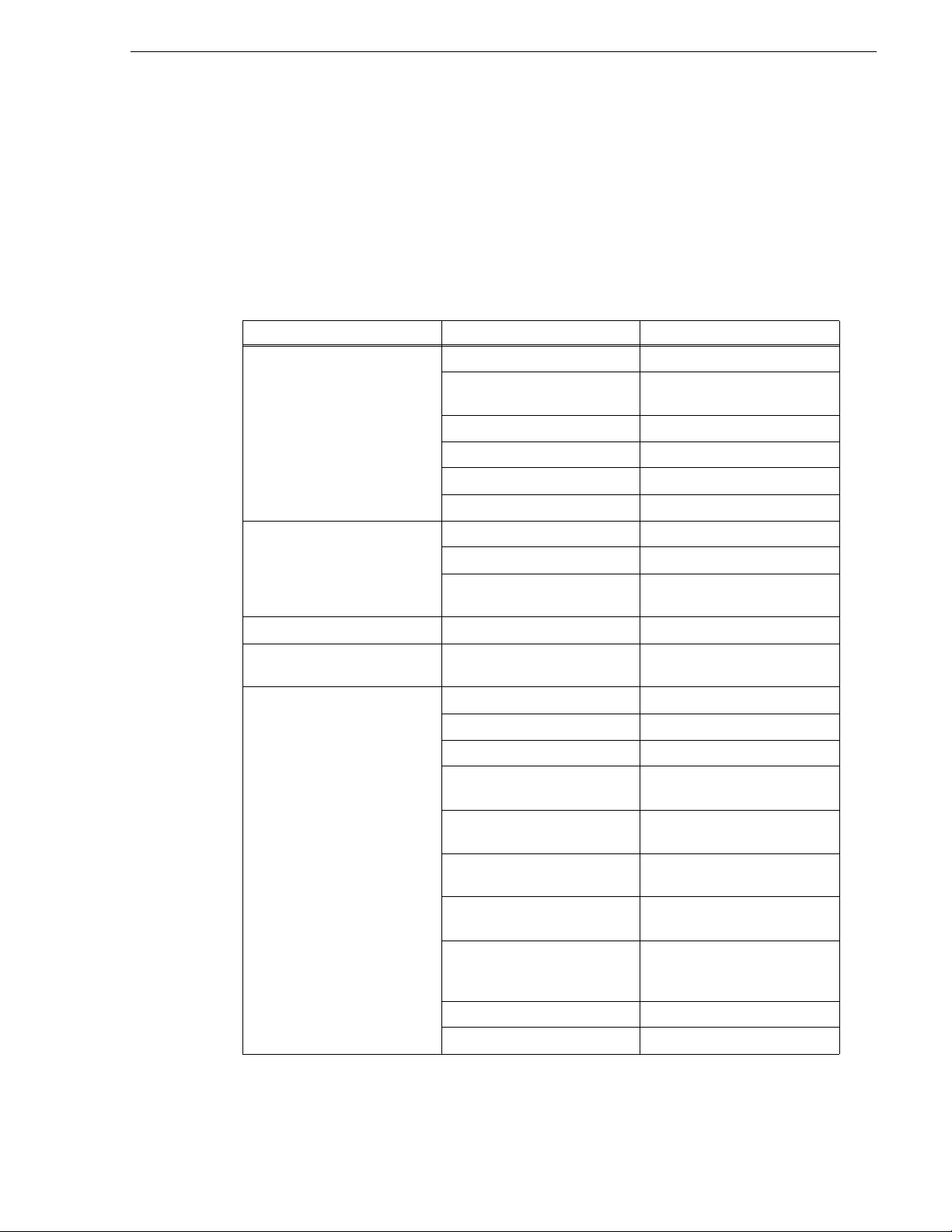
Table of Contents
Table of Contents...............................................................................................5
Introduction.........................................................................................................9
Grass Valley Product Support.................................................................................12
Web Technical Support......................................................................................12
Telephone Support.............................................................................................12
Waste Electrical and Electronic Equipment Directive.........................................14
Chapter 1 Component Names and Functions
Component names and functions of the K2 Dyno Controller..................................16
Front panel ............................. ...... ...... ..... ...... ................................. ...... ...... ..... ...16
Front...................................................................................................................17
Rear....................................................................................................................18
Button names and functions....................................................................................19
About Shift button operations.............................................................................21
Chapter 2 Starting Up and Shutting Down
Starting up...............................................................................................................24
Starting up the K2 Dyno Controller.....................................................................24
Creating a new session......................................................................................24
Changing the channel configuration for standard channels ...............................25
Changing the channel configuration for ChannelFlex Suite features .................31
Using the existing sessions................................................................................38
Deleting a session......................................... ..... ...... ...... ..... ...... ..... ....................39
Shutting down.......................................... ................................. ...... ..... ...... ...... ..... ...41
Shutting down the K2 Dyno Controller ...............................................................41
Switching to the Windows OS (maintenance mode) ..........................................42
Chapter 3 Tutorial
Startup and channel configuration...........................................................................44
Performing a calibration ..........................................................................................48
Importing keywords.................................................................................................49
Live playback and replay.........................................................................................51
Switching cameras..................................................................................................53
Switching camera angles....................................................................................53
Replaying the same scene again with another angle.........................................53
Marking and cueing up............................................................................................54
About the cursor colors.......................................................................................56
Storing and playing scenes in a highlight................................................................57
Creating and playing a playlist ................................................................................59
Chapter 4 Playback
Components in the HOME screen...........................................................................62
Starting and stopping a recording.................................................. .........................65
Live playback......................................................................................................65
Stopping a recording..........................................................................................66
Replay.....................................................................................................................66
Switching cameras..................................................................................................68
Switching camera angles....................................................................................68
Replaying the same scene with another angle...................................................68
About play speed.......................................... ...... ................................. ...... ...... ..... ...69
Audio level settings.................................................................................................72
On-air preview mode and multi-channel mode........................................................73
Playback operations in the on-air preview mode................................................73
Switching the operation target channel in the multi-channel mode ....................77
Synchronizing playback status for multi-channel (Gang) mode channels..........78
Transferring the channel control................... ...... ..... .................................. ...... ........80
15 April 2010 K2 Dyno Controller User Manual 5
Page 6

Table of Contents
Chapter 5 Marking Function
Chapter 6 Highlight
Offering the channel control (Offer mode).......................................................... 80
Obtaining the channel control............................................................................. 81
Checking the contents of the Recycle Bin (trash box) ............................................ 81
Error list display....................................................................................................... 83
Components in the MARK screen........................................................................... 86
Marking and cueing up............................................................................................87
Marking and cueing up.......................................................................................87
About the cursor colors ......................................................................................88
About multiple selection of items........................................................................89
About marking and scenes.................................................................................89
Cueing up to the previous or next item using the JOG knob (Browse mode)..... 91
Cueing up an item by specifying it with a number..............................................92
Entering the logging information .............................................................................93
Entering information with the touch panel..........................................................93
Entering information with shortcuts....................................................................95
Trimming................................................................................................................. 96
Components in the HIGHLIGHT screen..................................................................100
About shot box indications .................................................................................102
Storing and removing scenes in a highlight ............................................................102
About shot boxes.......................................... .................................. ..... ...... ...... ...103
Storing scenes to a highlight.............................................................................. 103
Removing stored scenes in a highlight............................................................... 104
Match frame operations from highlights to the record train..................................... 104
Trimming in a highlight............................................................................................ 105
Managing highlight bins ..........................................................................................108
Creating a new bin .............................................................................................108
Editing bin names...............................................................................................110
Setting bookmarks in a highlight............................................................................. 111
Setting bookmarks.............................................................................................. 111
Jumping to a bookmark......................................................................................112
Transferring items (SEND function) ........................................................................ 113
Transferring an item to a specified locatio n......................... ...............................113
Checking the transfer progress..........................................................................114
Chapter 7 Editing a Playlist
Components in the PLAYLIST screen ....................................................................118
Storing and deleting scenes in a playlist.................................................................120
Storing events to a playlist .................................................................................120
Deleting events from a playlist ....................................................... ..... ............... 121
Match frame operations from playlists to the record train....................................... 121
Trimming in a playlist .............................................................................................. 121
Adding a transition/audio cross fade.......................................................................125
Editing the audio ..................................................................................................... 126
Expanding audio to the previous and next events (audio split)..........................126
Playing events in a playlist...................................................................................... 128
Playing a playlist................................................................................................. 128
Playing a playlist according to target duration....................................................130
Managing playlists................................................................................................... 133
Creating a new playlist.......................................................................................133
Editing the property of a playlist......................................................................... 134
Switching playlists.............................................................................................. 135
Storing a playlist to another playlist as an event................................................137
Managing playlists in a bin................................................................................. 139
6 K2 Dyno Controller User Manual 15 Apri l 2010
Page 7

Chapter 8 Library Function
Components in the LIBRARY screen......................................................................142
Storing and removing scenes in a library................................................................143
Storing items in a library.....................................................................................143
Removing stored scenes in a library ..................................................................144
Managing library bins..............................................................................................145
Creating a new bin..............................................................................................145
Playing a clip created in another application......................................................147
Setting bookmarks in a library.................................................................................148
Chapter 9 Search Function
Components in the SEARCH screen......................................................................150
The search result screen for marks/scenes........................................................150
The search result screen for highlights/playlists, and libraries...........................152
Entering search conditions......................................................................................153
Setting a search condition..................................................................................153
Setting multiple search conditions......................................................................157
Simple search..........................................................................................................161
Chapter 10 Settings
Controller settings ...................................................................................................164
Record train length allocation settings................................................................164
Clip settings........................................................................................................166
Playback operation settings 1 (the channel settings, player settings)................167
Playback settings 2 (JOG speed, pre/post-roll definitions).................................169
Playback settings 3 (mark move, cut point, lever engage).................................170
Playback settings 4 (operation channel lock).....................................................171
Mix effect settings...............................................................................................171
Panel settings (the confirmation dialog setting, audio level meter setting)......... 173
Setting the T-Bar ................................................................................................174
Setting the file export..........................................................................................175
Setting a destination...........................................................................................176
Deleting a session......................................... ..... ...... ...... ..... ...... ..... ....................180
Other settings.....................................................................................................182
Default logging settings......................................................................................183
Exporting a log ........................................................................................................184
Checking the version...............................................................................................185
Play option settings.................................................................................................185
Editing and storing keywords ..................................................................................187
Editing keywords ................................................................................................187
Importing/Exporting keywords or icons...............................................................191
Importing/Exporting.................................................................................................193
Importing the CONFIG information.....................................................................194
Exporting the CONFIG information.....................................................................194
Backing up items by exporting them...................................................................195
Restoring items by importing them.....................................................................197
Initializing the views........................... ...... ................................. ...... .........................198
Calibration...............................................................................................................199
Assigning the network ports....................................................................................200
Chapter 11 Connecting a Second Display
Components in the expansion screen.....................................................................204
Menu bar ............................................................................................................206
System information..................................................................................... ........207
Playback item information ..................................................................................208
Play option settings............................................................................................208
Controller button.................................................................................................209
15 April 2010 K2 Dyno Controller User Manual 7
Page 8

Table of Contents
Chapter 12 Appendix
Display switch..................................................................................................... 211
Summit/camera selection...................................................................................211
Jog...................................................................................................................... 212
Button Operation.....................................................................................................214
Restrictions on the LoopRec setting ....................................................................... 217
Index......................................................................................................................219
8 K2 Dyno Controller User Manual 15 Apri l 2010
Page 9
Introduction
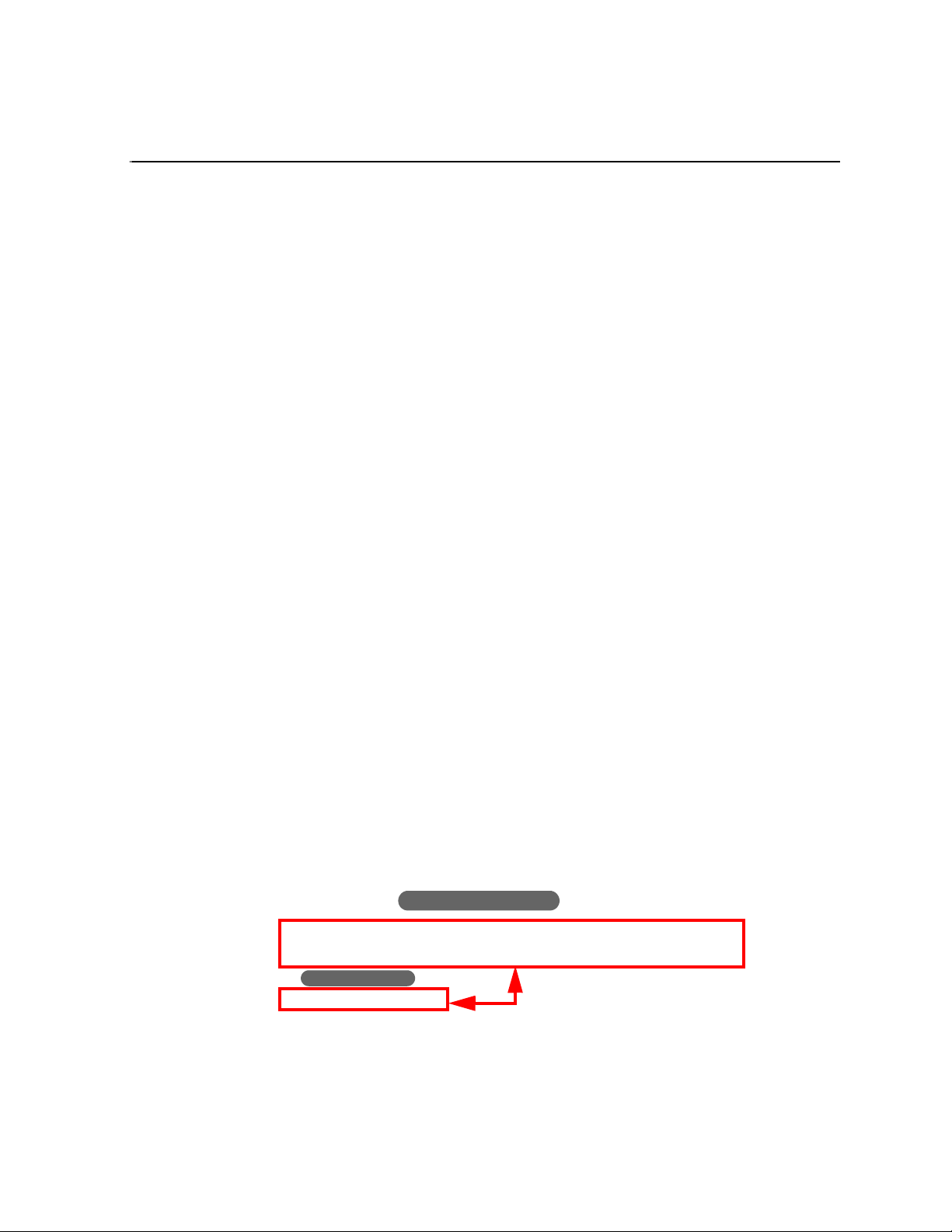
Button operation
2. Touch the PLAYLIST tab to display the PLAYLIST screen, and then touch the
event box.
Press the Add PL button.
Button operation
Operation results are the same
Summary
The K2™ Dyno™ Controller is a controller that is designed to provide fast and
accurate operations controlling a K2 S ummit™ Prod uction Client o r K2 Solo™
Media Server. Operations include searching, replaying video or scenes, storing
highlights, and creating playlists. The K2 Dyno Controller can control channels
configured for ChannelFlex™ Suite features on the K2 system.
K2 Dyno Controller features are as follows:
• Its simple system configuration en ables comfo rtable operations even in a limited
sp
ace.
• The touch panel allows for intuitive operations. For operations that require more
accuracy, you can operate the controller using only the physical buttons.
• Connecting a keyboard, mouse, and second display allows you to set up a more
comfortable operating environment.
• All of the ed ited data (excluding Mark and Scene ) is saved in the K2 Summit
Production Client. Theref ore, you can continue your operation without losin g your
data in the unlikely event of a malfunction in the K2 Dyno Controller.
• The settings of the K2 Dyno Controller , that you set in t he CONFIG screen, can be
exported and imported to anot her K2 Dyno Controller, which en ables you to set up
the same settings easily.
• The controller provides easy mix effect editing. A diss olve effect can be applied t o
a scene switch just by t ouchin g th e panel . In addi tion, thi s can be perfo rmed usi ng
only 1 channel.
How to read this manual
This User Manual contains the operation procedures to use the K2 Dyno Controller,
concerning the editing functions that are often used in a live event broadcast.
Operations can be performed intuitively with the touch panel and buttons. Operation
proce
dures with the touch panel are mainly described; however, button operations are
mentioned together when the same operations can be performed with the buttons. You
can also perform important operations with the physical buttons.
For example, when operations are described as follows, the operation results by
orming step 2 and will be the same.
perf
In addition, if there is eno ugh room in your edit ing spac e, a mouse, keyboa rd, numerica l
keypa
d, or second display can be connected to the controller for comfort ab le operations
that suit your preferences. If you are using a controller with a mouse or keyboard
connected, a touch panel operation can be replaced either by a click operation with a
mouse, or by a value entry operation with a keyboard or numerical keypad, unless
otherwise noted.
15 April 2010 K2 Dyno Controller User Manual 9
Page 10

Introduction
This User Manual consists of the following:
Chapter 1, Component
It describes the names and functions of the components and buttons on the K2 Dyno
Controller. For more detailed descrip tion about the individual functions, see the referenced
section.
Chapter 2, Starting Up and Shutting Down:
It describes how to start up and shut down the K2 Dyno Controller.
Chapter 3, Tut
It describes a basic editing operation workflow that is used in a live broadcast, taking a
sp
ecific example.
Chapter 4, Playba
It describes the components in the HOME screen and basic operations, such as live
play
backs or replays.
Chapter 5, Marking
It describes op er ati ons to mark a point on th e record train a nd c ue it up, to recor d I n and
Out poi
logging information, such as names, keywords or ratings, to the marks.
Chapter 6, High
It describes operations such as storing an important scene as a highlight and managing
highl
ight items in a bin.
ori
nts to create a scene, and to trim a scene. It also explains operations to enter
Names and Functions:
al:
ck:
Function:
light:
Chapter 7, Edit
It describes editing operations such as creating a playlist, trimming an event, adding
ef
fects, and using the audio split.
Chapter 8, Librar
Items saved in a l ibr ary will remain wit hout be ing deleted even if a session is delete d. I t
desc
ribes operations such as storing items to a library and managing a library.
Chapter 9, Sear
It describe s how to search items.
Chapter 10, Se
It describes information such as various settings of the K2 Dyno Controller and import/
expor
t of your data.
Chapter 11, Connec
You can connect a second display to perform operations in the expansion screen. It
desc
ribes the components in the expansion screen.
Chapter 12, Appe
It provides the operation list when pressing the buttons and the restrictions on the
Loop
Rec setting.
ing a Playlist:
y Function:
ch Function:
ings:
tt
ting a Second Display:
ndix:
10 K2 Dyno Controller User Manual 15 April 2010
Page 11

Getting more information
The following sections help you find the information you need in product manuals
and elsewhere.
K2 documentation
Read the following descriptions to l ocate the information you need.
K2 Dyno Replay System Quick Start Guide — You receive this guide in the product
packaging with your K2 Dyno Replay Controller. The Quick Start Guide provides
step-by-step ins tallat ion instr uctions f or basic in stall ation and operation of the repl ay
system, which includes the K2 Dyno Replay Controller and the K2 Summit
Production Client.
Getting more information
Release Notes —
The release notes contain the latest information about the software
shipped on your system. There are K2 Release Notes and K2 Dyno Repla y Controller
Release Notes. The information in release notes includes software upgra de instructions,
software specifications and requirements, feature changes from the previous releases,
and any known problems. Because re lease notes contain the la test information, they a re
printed out rather than included in the Documentation CD-ROM.
K2 Documentation CD — Except for the release notes, the full set of support
documentation, including this manual, is available on the Documentation CD-ROM
that you received with your K2 Summit Production Client. The K2 Documentation
CD includes the following documents:
K2 Dyno Replay System Quick Start Guide — As described above.
•
•
K2 Dyno User Manual — Describes K2 Dyno applicatio ns and provides i nstructions
for configuring and operating the product.
•
K2 Dyno Service Manual — Contains information on servicing and maintenance.
•
K2 Dyno Installation Manual —
Provides instructions for a installing a K2 Dyno Replay
System using a K2 Solo Media Server or a K2 Summit Production Client that is not part
of a Dyno-Pack and has not been previously controlled by a K2 Dyno Controller.
• K2 Summit Production Client Quick Start Guide — The Quick Start Guide provides
step-by-step installation instructions for basic installation and operation of K2
systems, including recording and playing clips.
•
K2 AppCenter User Guide — Describes K2 applications and provides instructions
for configuring and operating the product.
•
K2 System Guide — Contains the product specifications and step-by-step
instructions for modifying system settings.
•
K2 Cabling Guide — Contains diagrams for cabling the devices of the K2 Storage
Area Network.
•
K2 SAN Installation and Service Manual — Conta ins installa tion, configu ration, and
maintenance procedures for shared storage options.
•
RAID Instruction Manuals — There is an Instruc tion Manual for each typ e of RAI D
storage device that can be a par t of a K2 system. These manuals contain proce dures
for configuring and servicing the device.
•
K2 Client Service Manual — Contains information on servicing and maintenance.
15 April 2010 K2 Dyno Controller User Manual 11
Page 12

Introduction
NetCentral documentation
Grass Valley Web Site
The NetCentral product has its own documentation set, described as follows:
•
NetCentral Quick Star t Guide — Pr ovides an overview o f the i nstalla tion proc ess to
quickly set up and run NetCentral.
•
NetCentral Installation Guide — Identifies requirements and procedures to correctly
set up servers and devices, as well as provides detailed instructions to install and
configure NetCentral software.
•
NetCentral User Guide — Describes how to use the NetCentral Manager to monitor
devices.
•
NetCentral Help — From the NetCentral inter face acce ss on-line help. Selec t Help |
NetCentral Help Topics
Also find information about monitoring a specific product in that product’s manuals.
This public Web site contains all the latest manuals and documentation, and
additional support information. Use the following URL.
.
http://www.grassvalley.com.
Grass Valley Product Support
To get technical assi stance, check on the statu s of a question, or to r eport a new issues,
contact Grass Valley Product Support via e-mail, the Web, or by phone or fax.
Web Technical Support
To access support i nformation on t he Web, visit th e product suppo rt Web page on t he
Grass Valley Web site. You can download software or find solutions to problems.
World Wide Web:http://www.grassvalley.com/support/
Technical Support E-mail Address:gvgtechsupport@grassvalley.com
Telephone Support
Use the following information to contact Product Support by phone.
International Support Centers
Our international support centers are available 24 hours a day, 7 days a week.
Support Center Toll free In country
France +800 80 80 20 20 +33 1 48 25 20 20
United States +1 800 547 8949 +1 530 478 4148
12 K2 Dyno Controller User Manual 15 April 2010
Page 13
Authorized Local Support Representative
A local support represen ta ti ve ma y be avai l abl e in your count ry. To locate a support
cen
ter during normal local business hours, refer to the following l i st. This list is
regularly updated on the website for Grass Valley Product Support
(http://www.grassvalley.com/support/contact/phone/)
After–hours local phone support is also available for warranty and contract
customers.
Region County Telephone
Asia China +86 10 5883 7575
Grass Valley Web Site
Hong Kong, Taiwan, Korea,
Macau
Japan +81 3 6848 5561
Southeast Asia - Malaysia +603 7492 3303
Southeast Asia - Singapore +65 6379 1313
India +91 22 676 10300
Pacific Australia 1 300 721 495
New Zealand 0800 846 676
For callers outside Australia or
New Z
ealand
Central America, South America All +55 11 5509 3440
North America North America, Mexico,
Caribbean
Europe UK, Ireland, Israel +44 118 923 0499
Benelux – Netherland s +31 (0) 35 62 38 421
Benelux – Belgium +32 (0) 2 334 90 30
France +800 80 80 20 20;
Germany, Austria,
Ea
ste
rn Europe
Belarus, Russia, Tadzhikistan,
aine, Uzbekistan
Ukr
+852 2531 3058
+61 3 8540 3650
+1 800 547 8949;
+1 530 478 4148
+33 1 48 25 20 20
+49 6150 104 444
+7 095 258 09 20;
+33 (0) 2 334 90 30
Nordics (Norway, Sweden,
Finland, Denmark, Iceland)
Southern Europe – Italy Rome: +39 06 87 20 35 28 ; +39
Southern Europe – Spain +34 91 512 03 50
Switzerland +41 56 299 36 32
+45 40 47 22 37; +32 2 333 00 02
20 35 42. Milan: +39 02 48
06 87
41 46 58
15 April 2010 K2 Dyno Controller User Manual 13
Page 14
Introduction
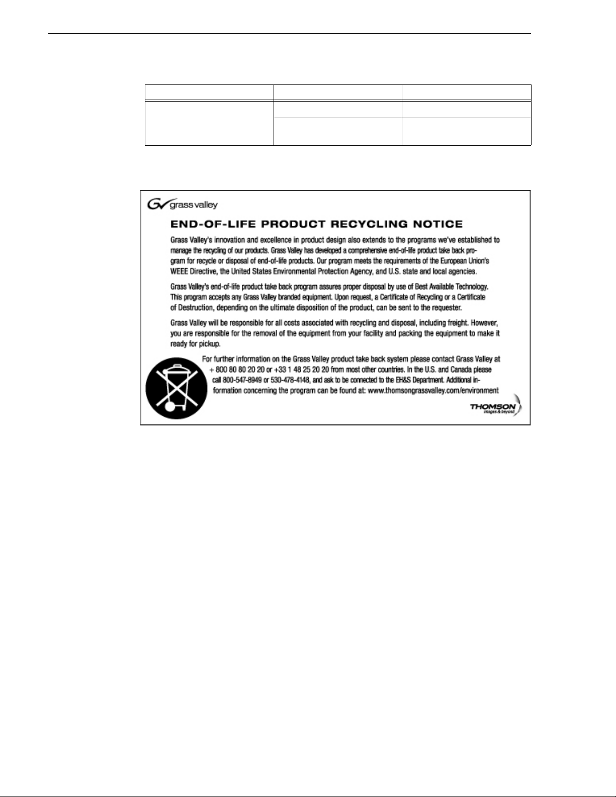
Waste Electrical and Electronic Equipment Directive
Region County Telephone
Middle East, Near East, Africa Middle East +971 4 299 64 40
Near East and Africa +800 80 80 20 20;
+33 1 48 25 20 20
14 K2 Dyno Controller User Manual 15 April 2010
Page 15

Chapter 1
Component Names and Functions
This chapter consists of the following :
• "Component names and functions of the K2 Dyno Controller" on page 16
• "Button names and functions" on page 19
15 April 2010 K2 Dyno Controller User Manual 15
Page 16
Chapter 1 Component Names and Functions
(1)
(3)
(2)
(4)
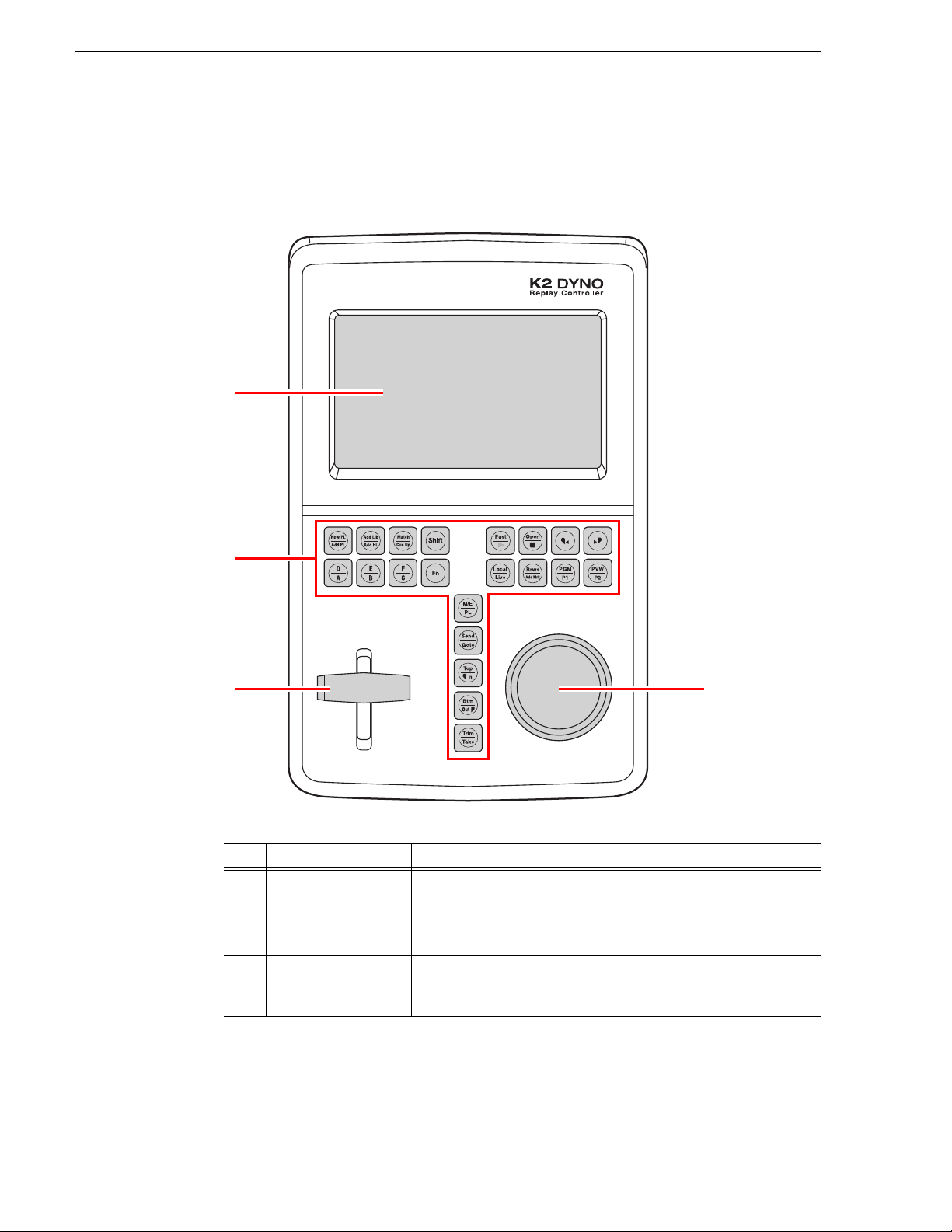
Component names and functions of the K2 Dyno Controller
Front panel
No. Name Function
(1) Touch panel
(2) Operation button
16 K2 Dyno Controller User Manual 15 April 2010
(3) T-Bar
You can touch the screen directly for data selections or operations.
You can perform many of the more common operations quickly with
these push butto ns. For de scription s of each b utton, see "Button na mes
and functions" on page 19.
A bar for to control playback speed. The 0% and 100% positions o f bar
operations can be fine-tuned. For more information about the setting,
see "Calibration" on page 199.
Page 17

Front
(3)
(2)(1)
No. Name Function
(4) JOG knob
A knob for frame forward, frame back, fast forward, and rewind
operations. The JOG speed and the idle of the JOG knob can be set to
suit your preferences. See "Playback settings 2 (JOG speed, pre/
post-roll definitions)" on page 169 for details on how to set the JOG
speed setting, and see "Calibration" on page 199 for details on how to
set the JOG knob idle setting.
Front
No. Name Function
(1) Stereo jack
(2) Volume control
(3) USB port
Connects to a device such as headphones.
Adjusts the volume.
Connects to a keyboard, mouse, or USB storage device.
15 April 2010 K2 Dyno Controller User Manual 17
Page 18
Chapter 1 Component Names and Functions
(1)
(2)
(4) (5) (6)(3)
(3)
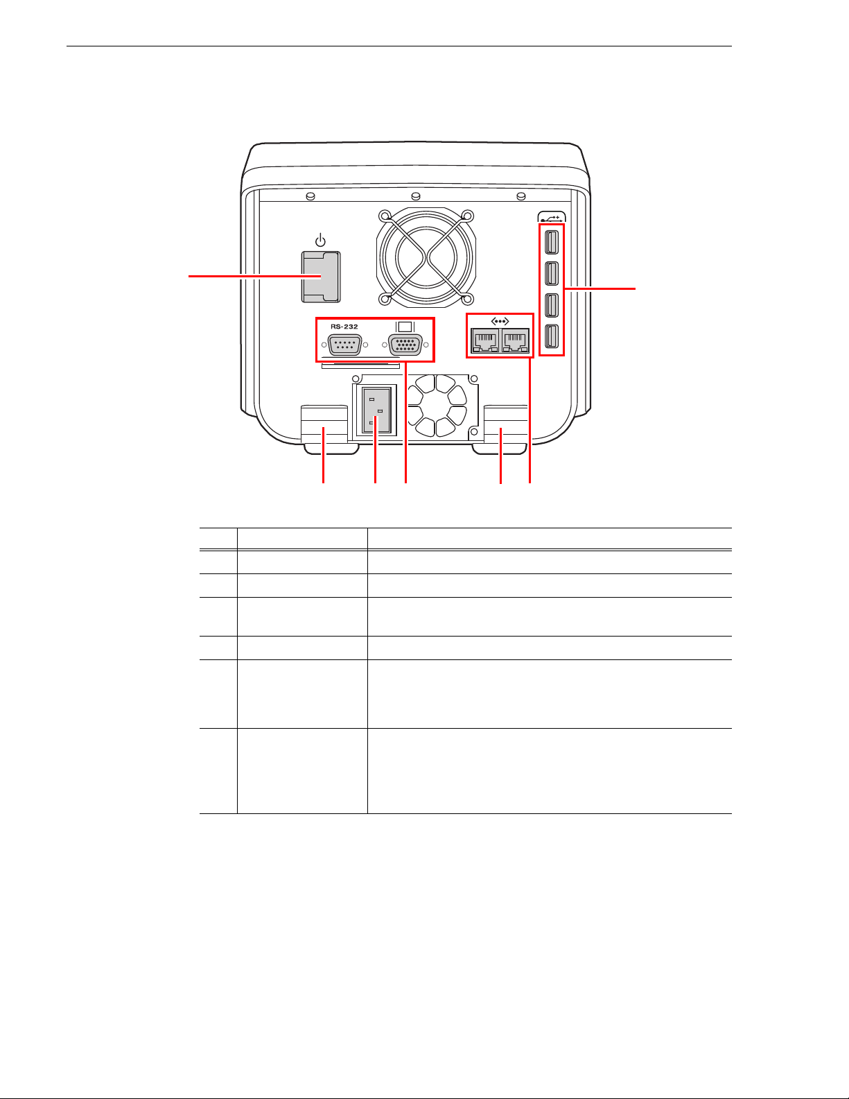
Rear
No. Name Function
(1) Power button
(2) USB port
(3) Cable hook
(4) Power connector
(5) D-sub 15 pin
connector
(6) GigE port
Turns the power to the K2 Dyno Controller on or off.
Connects to a keyboard, mouse, or USB storage device.
You can hook cables such as power cables and VGA cables to prevent
them from being disconnected inadv ertently.
For connecting to the power supply.
Connects to a second display. Displays with 1024 x 768 resolution or
more are supported.
For more information about the components in the expansion screen,
see "Connecting a Second Display" on page 203.
Connects the K2 Dyno Contro ller to the K2 Summit P roduction Cl ient
via Gigabit Ethernet.
The GigE ports can be used for the transfer and co ntrol purposes
separately.
For more information, see "Assigning the network ports " on page 200.
NOTE: Be sure to use the cables, such as power cable and other cab les, included in
this product.
18 K2 Dyno Controller User Manual 15 April 2010
Page 19
Button names and functions
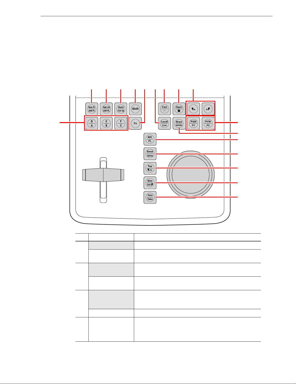
(1) (2) (3) (4) (6) (7)(10) (8) (9)
(12)
(11)
(13)
(5)
(14)
(15)
(16)
(17)
Some buttons have function names at the top and bottom. To use a bottom function,
just press the des ired but ton. To use a top functio n (functi ons indi cated by the shade d
area in the table), press the
information on how to use the
page 21.
Shift button, and then press the desired button. For more
Shift button, see "About Shift button operations" on
Button names and functions
No. Name Function
(1) New PL
Add PL
(2) Add Lib
Add HL
Creates and displays a new playlist.
Stores the selected item to a playlist.
When a bin is selected, all the items in the bin are stored to a playlist.
Stores the selected item to a library.
When a bin is selected, all the items in the bin are st ored to a library.
Stores the selected item to a highlight.
When a bin is selected, all the items in the bin are stored to a highlight.
(3) Match
Cue Up
(4) Shift
When the playback pointer is in a highlight or playlist, press the
Match button to move the playback pointer to the position with the
same timecode on the record train for the current angle.
Cues up to the selected item.
Press this button to perform the functions indicated at the top of the buttons,
or to perform the functions indicated at the top of the menu panels that are
displayed at the bottom of the touch panel. For more information on how to
Shift
use the
button, see "About Shift button operations" on page 21.
15 April 2010 K2 Dyno Controller User Manual 19
Page 20
Chapter 1 Component Names and Functions
No. Name Function
(5) Camera selection
(6) Fn
(7) Fast
Play
(8) Open
Stop
(9) Previous/Next
(10) Local
Live
(11) Brws
Add Mrk
(12) PGM/PVW
P1/P2
Switches the camera angles, which are assigned to A, B, C, D, E, or F.
Turns to the function mode. If you press the Fn button and then press
a corresponding button, the button action that is perf ormed may be
different from the normal one. For more information, see the operation
instructions in each chapter.
Switches to the Fast JOG mode. This is toggle switch, so it turns off if
you press this button when it is in Fast mode. The speed for the fast
forward and rewind operations using the JOG knob becomes faster.
The Previous/Next buttons light up in green while in the Fast JOG
mode.
You can also set the controller so that the normal JOG m ode an d F ast
mode are switched automatically. For more information, see
JOG
"Playback sett ings 4 (operation channel lock)" on page 171.
Plays the item with the 100% sp eed.
Press this while an item is selected to create a new playlist and stores
the item to the playl ist.
Press this while a bin or playlist is selected to open the bin or playlist.
Stops the playback.
Moves the playback pointer. The action after the move depends on the
current condition. For example, if you press this whi le cueing up to an item,
the controller cues up to the In poi nt of the previous/next item, If y ou press
this during an item playback, the controller plays the previous/next item
after the playback p o inter mo v es to the In point of the previous/next i tem.
You are controlling your repl ay in still, slow motion, or norma l playout
mode. The recording of the live video continues while you are in this
mode.
You are watching the live video of the s elected channel being
recorded.
Switches to the Browse mode. In the Browse mode, you can use the
JOG knob to consecutively m ove the p layback pointe r to the previo us
or next items for cueing up.
Adds a mark on the record train.
Switches to the on-air preview or multi-channel mode. For more
information, see "On-air preview mode and multi-channel mode" on
page 73.
While in the on-air preview mode, it switches the operation target
channel. If you press the P1 button, the pr og ram ch anne l ( the c hanne l
for an on-air broadcast) becomes the target for operations. If you press
the P2 button, the preview channel becomes the target for operations.
While in the multi-chann el mode, it switch es the operation t arget to the
h
annel assigned to the P1/P2 button. In a ddition, pressing the P1 and
c
P2 buttons at the same tim e while in the multi-c hannel mo de switches
to the Gang mode.
For more information, see "On-air preview mode and multi-channel
mode" on page 73.
20 K2 Dyno Controller User Manual 15 April 2010
Page 21
No. Name Function
(13) M/E
PL
(14) Send
Goto
(15) Top
In
(16) Btm
Out
(17) Trim
Take
Switches to the Flying M/E mode . Effects are added when switching
angles or changing cue up poin ts during a replay of an item.
Displays the PLAYLIST screen. Press this in the PLAYLIST screen to
perform the following: if a playback pointer is in the playlist, the
controller cues up to the begin ni ng of the playlist, and if playback
pointer is not in the playlist, the playback pointer moves to the point
where the previous playlist stopped its playback.
Copies the selected item to the destinatio n that you set in
"NETWORK" on the CONFIG screen. For more information, see
"Transferring items (SEND function)" on page 113.
Cues up to an item by entering a numbe r .
Press this during an item (Mark, Scene, Highlight, Event, and Library)
playback to cue up to the beginning (or the In point, depending on the
item) of the item retaining the ongoing playback.
Adds the In point of a mark/scene, or changes the In point when
trimming a highlight/event.
Press this during an item
playback to cue up to the end of the item retaining the ongoing playback.
Adds the Out point of a mark/scene, or changes the Out point when
trimming a highlight/event.
Switches to the trim mode.
During a playlist playback, press this butt on to begin the playbac k of
the next event. In a value entry screen, press this to confirm your entry
and return to the previous screen.
While in the trim mode, it exits the trim mode.
If you press this during the on-air preview mode, the item that is put into
standby or being p layed in the pre view chann el will b e loade d and pl ayed
in the program channel. Fo r more information about the on-air preview
mode, see "On-air preview mode and multi-channel mode" on page 73.
About Shift button operations
(Mark, Scene, Highlight, Event, and Library)
About Shift button operations
When a keyboard or display is connected to the K2 Dyno Controller, you can use the
Shift
[Shift] key on the keyboard or the
Shift
the
• For operations with the
button on the controller; however, the operations are different for each case.
Shift
Shift
If you press the
button once, it illuminat es in yel low and t he to p functi ons of
the controller button s and pa nel menu are enab led for only one time. After that , if
you press any bu tton or menu panel you want to per form, the
• For operations with the [Shift] key on the keyboard:
Press the button or menu panel you want to perform while holding do wn the [Shift]
key.While holding down th e [Shift] key, the t op functions o f the control ler buttons
and panel menu are enabled.
• For operations with the
If you press the
Shift
Shift
button, the button turn s light blue. After tha t, press the butt on
or menu panel you want to perform. In the expansion screen, if the
pressed once, the top functions of the controller buttons and panel menu are
Shift
enabled until the
15 April 2010 K2 Dyno Controller User Manual 21
button is pressed again.
button in the expansion screen instead of pressing
button on the controller:
Shift
button turns off.
button in the expansion screen:
Shift
button is
Page 22

Chapter 1 Component Names and Functions
22 K2 Dyno Controller User Manual 15 April 2010
Page 23

Chapter 2
Starting Up and Shutting Down
This chapter consists of the following :
• "Starting up" on page 24
• "Shutting down" on page 41
15 April 2010 K2 Dyno Controller User Manual 23
Page 24

Chapter 2 Starting Up and Shutting Down
Starting up
Starting up the K2 Dyno Controller
Before starting up th e K2 Dyno Contro ller, tur n on the K2 Summit Producti on Client
to use and start the application software in the Summit.
1. Turn on the K2 Summit Production Client.
2. Login K2 Summit Production Client with username (administrat or) and password
(ad
minK2).
3. Start up AppCenter on the K2 Summit Production Client with user name
(a
dministrator) and password (adminK2).
4. Turn on the K2 Dyno Controller.
• The power button is located on the rear side of the controller.
• T
he K2 Dyno Client software starts up automatically.
• When you start up the controller for th e first time, you need t o perform the init ial
settings.
•See "Changing the channel configuratio n for standard channels" on page 25 about
the initial settings, and see "Using the existing sessions" on page 38 about using
the existing sessions.
Creating a new session
NOTE: When you start up the K2 Dyno Controller for the first time, you need to
perform the initial settings. For information about the initial settings, see
"Changing the channel configuration for standard channels" on page 25.
1. Start up the K2 Dyno Controller.
• For information on how to start up th e controller, see "Starting up the K2 Dyno
Controller" on page 24.
24 K2 Dyno Controller User Manual 15 April 2010
Page 25
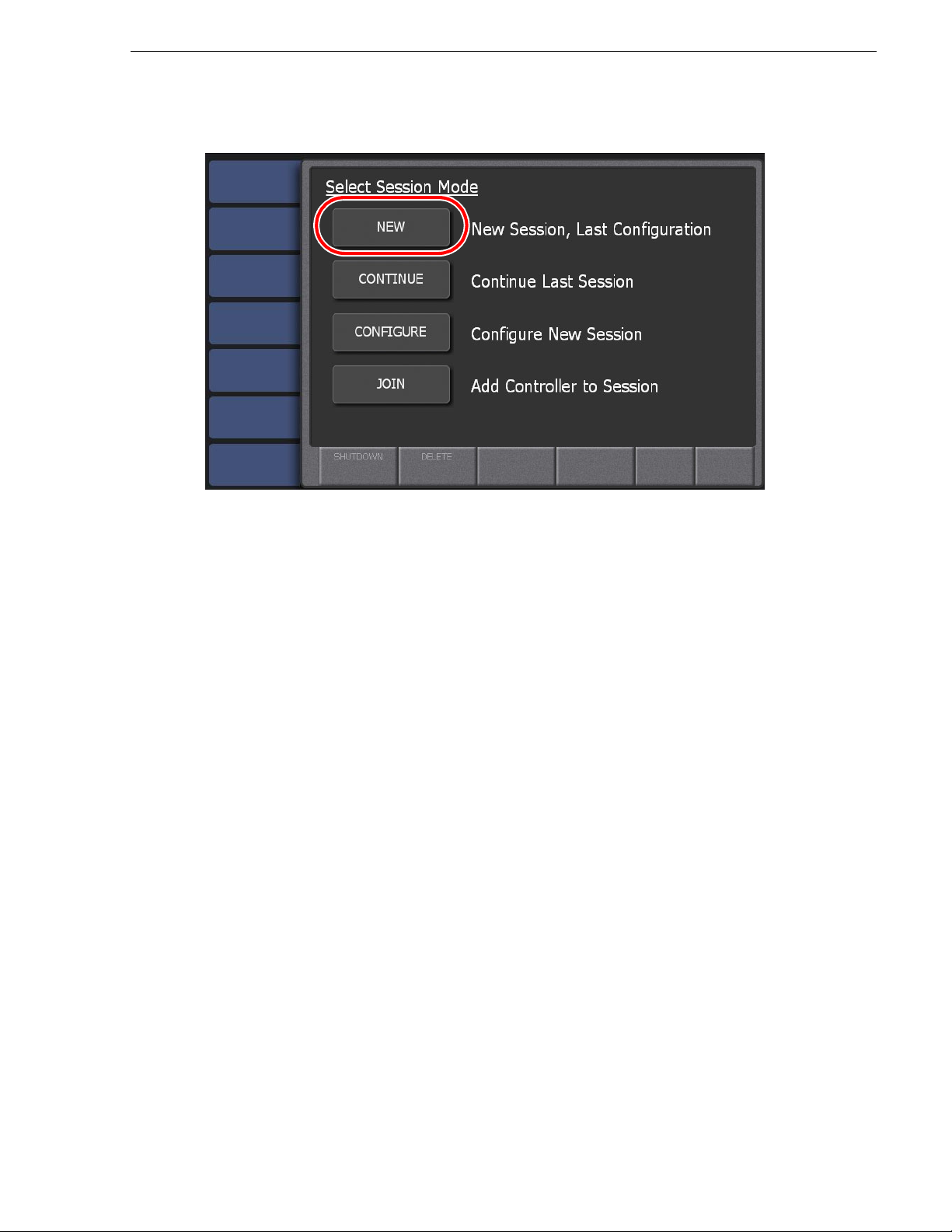
Changing the channel configuration for standard channels
2. Touch NEW.
• A new session for the same channe l configuration as you set for the last t ime is
ated.
cre
• The session that wa s used for the las t time ca n be dele ted b y touchi ng
after pressing th e
Shift button. For more info rmatio n on how to delete sessio ns,
DELETE
see "Deleting a session" on page 39.
• Check if the versions of App Center and K2 Dyno Client software are
compatible.
- If the K2 Dyno Controller cannot be started up, their major or minor vers ions are
not compatible.
- If a warning message asking you to choose whether or not to start up the K2 Dyno
Controller is displayed, their patch versions are not compatible.
Changing the channel configuration for standard channels
Use this procedure if controlling standard K2 system channels with the K2 Dyno
Replay Controller.
If controlling Multi-Cam, 3D/Video+Key, or Super Slo-Mo channels on the K2
Sum
mit Production Clie nt or K2 Solo Med ia Server, use the procedure "C hanging the
channel configuration for ChannelFlex Suite features" on page 31.
When you start up the K2 Dyno Controller for the first time or when you want to
cr
eate a session changi ng the previous channel co nfiguration, you ne ed to perform the
initial settings at the startup screen. Fo r the default settings, you c an set the settings
including the K2 Summit Production Client selection to be used and channel model
setting. On ce the initial s ettings are set, it is not necessary to set them with
CONTINUE from the next time.
NEW or
1. Start up the K2 Dyno Controller.
• For information on how to start up th e controller, see "Starting up the K2 Dyno
Controller" on page 24.
15 April 2010 K2 Dyno Controller User Manual 25
Page 26
Chapter 2 Starting Up and Shutting Down
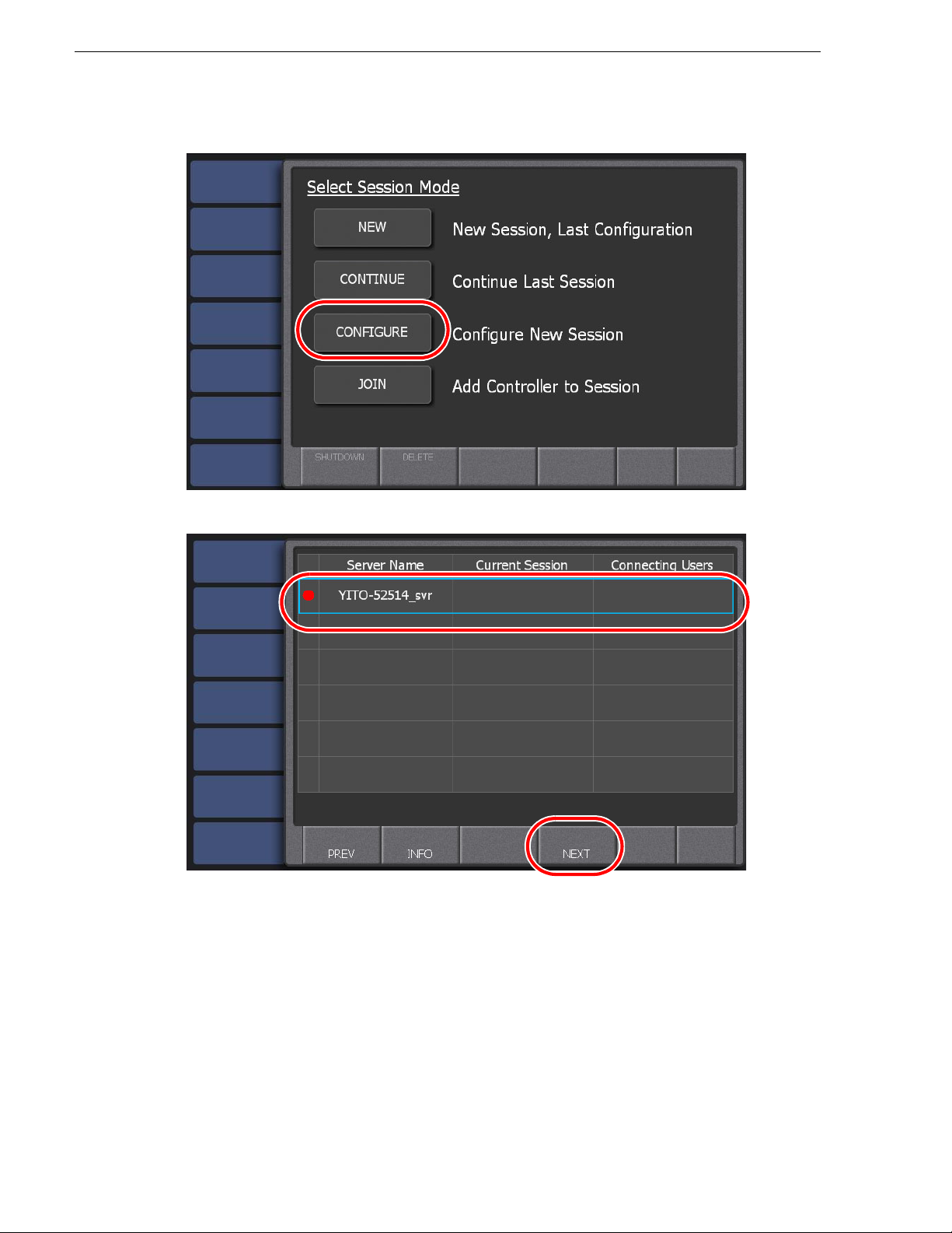
2. Touch CONFIGURE.
3. Select the Summit you want to use, and then touch
NEXT.
• Only the online Summit(s) are displayed. The Summit that was used for the last
me appears with a red circle.
ti
• Touch and select a Summit name, and then touch
INFO to display the
information for the Summit.
• If there is a ny s ess ion that is being br oad cas ted, its session na me wil l appear in
"Current Session". If there is any K2 Dyno Controller that is connected to the
Summit, their user name(s) will appear in "Connecting Users".
26 K2 Dyno Controller User Manual 15 April 2010
Page 27
Changing the channel configuration for standard channels
• Check if the versio ns of App Ce nter a nd K2 Dyno Cli ent so ftware are t he same.
- If the K2 Dyno Controller cannot be started up, their major or minor vers ions are
different.
- If a warning message asking you to choose whether or not to start up the K2 Dyno
Controller is displayed, their patch versions are different.
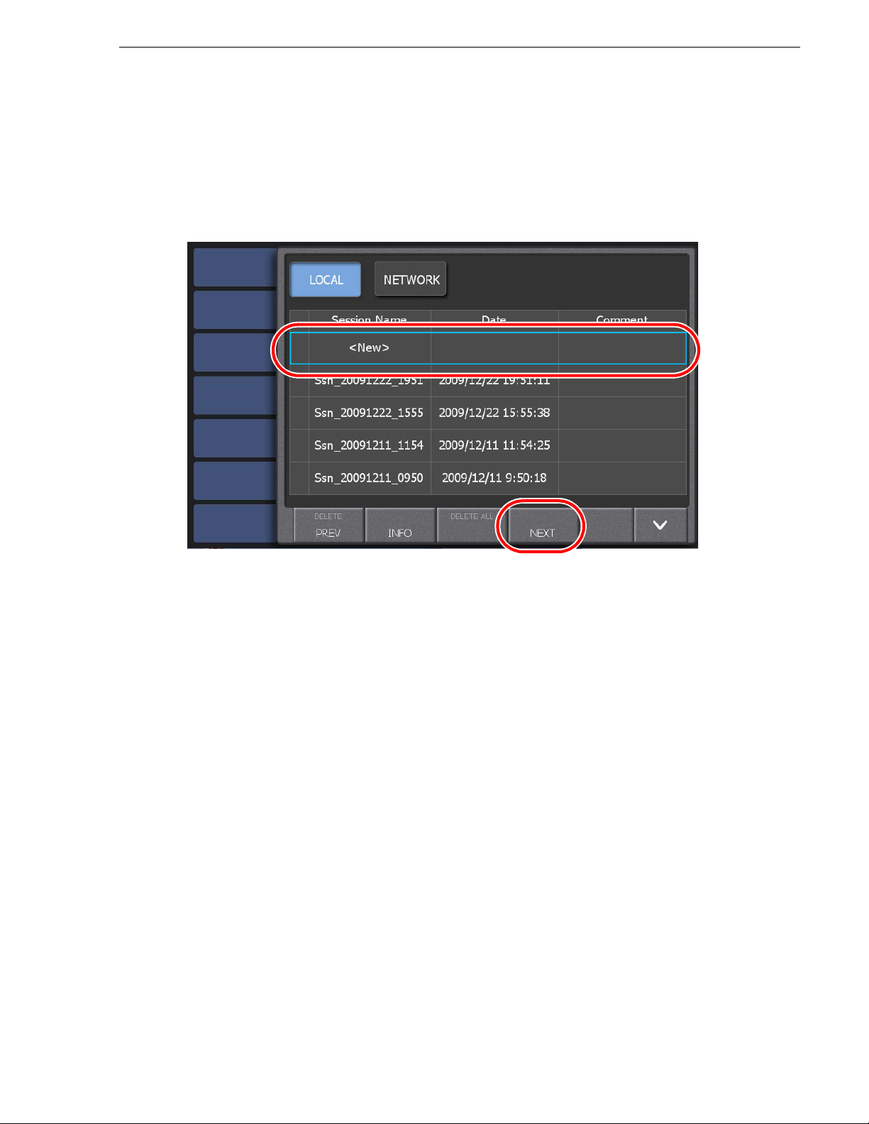
4. Select "New" from the session list, and then touch NEXT.
• Touching
Touching
LOCAL displays the list of sessions created in the local Summit.
NETWORK displays both the list of sessions created in the local
Summit and the list of sessio ns created in the net work Summit. The session th at
was used for the last time appears with a red circle. You can start a previous
session by touching
• Touch and select a sess ion name, and then touch
NEXT after selecting a session.
INFO to display the infor mation
for the session. You can edit a session name and comment in the information
screen.
15 April 2010 K2 Dyno Controller User Manual 27
Page 28
Chapter 2 Starting Up and Shutting Down
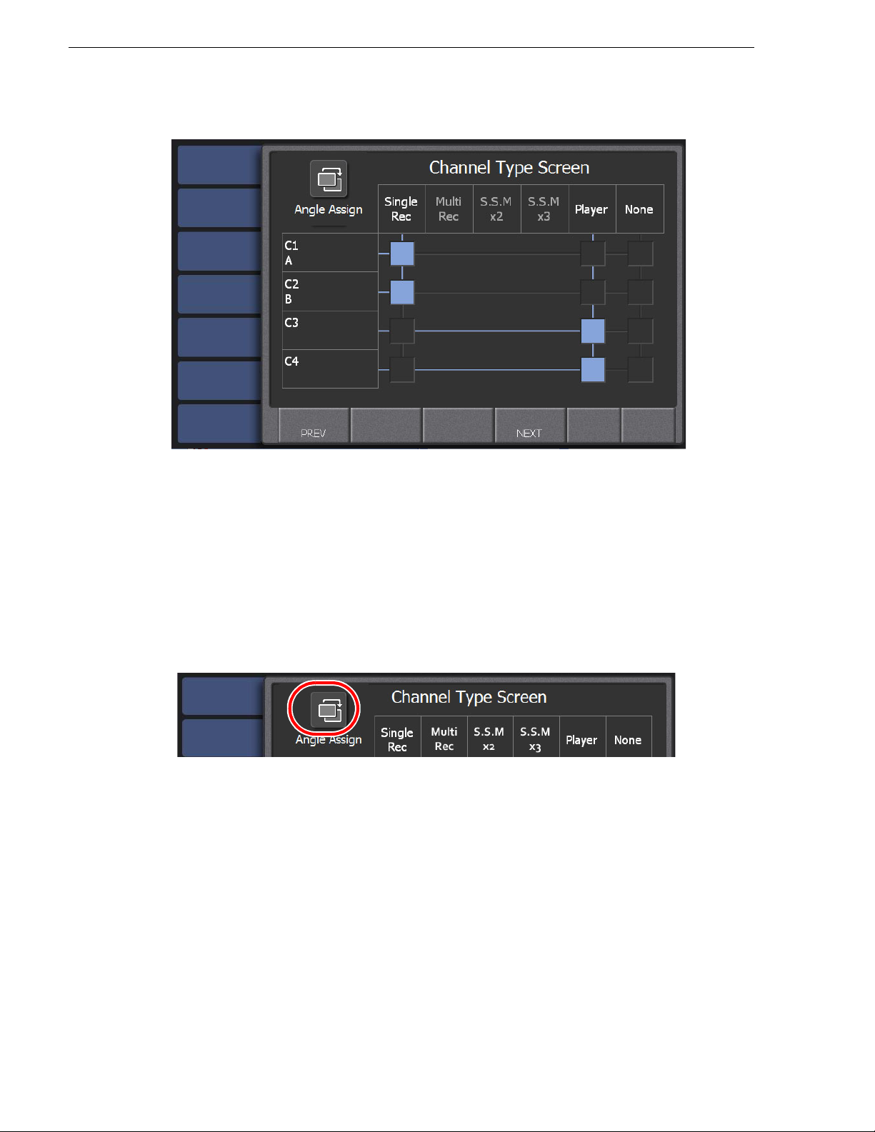
5. Set the use of the channels.
• Assi gn a channel's use by touching the rectangular panels for each channel from
C1 to C4 as follows:
- Single Rec – Standard record channel.
- Player – Standard play channel.
- None – The channel is not controlled by the K2 Dyno Controller. The K2
Summit/Solo channel can be used for other applications.
• The assigned camera angle is displayed for a channel that is set as a record
channel.
6. Touch the Angle Assign button.
28 K2 Dyno Controller User Manual 15 April 2010
Page 29
Changing the channel configuration for standard channels
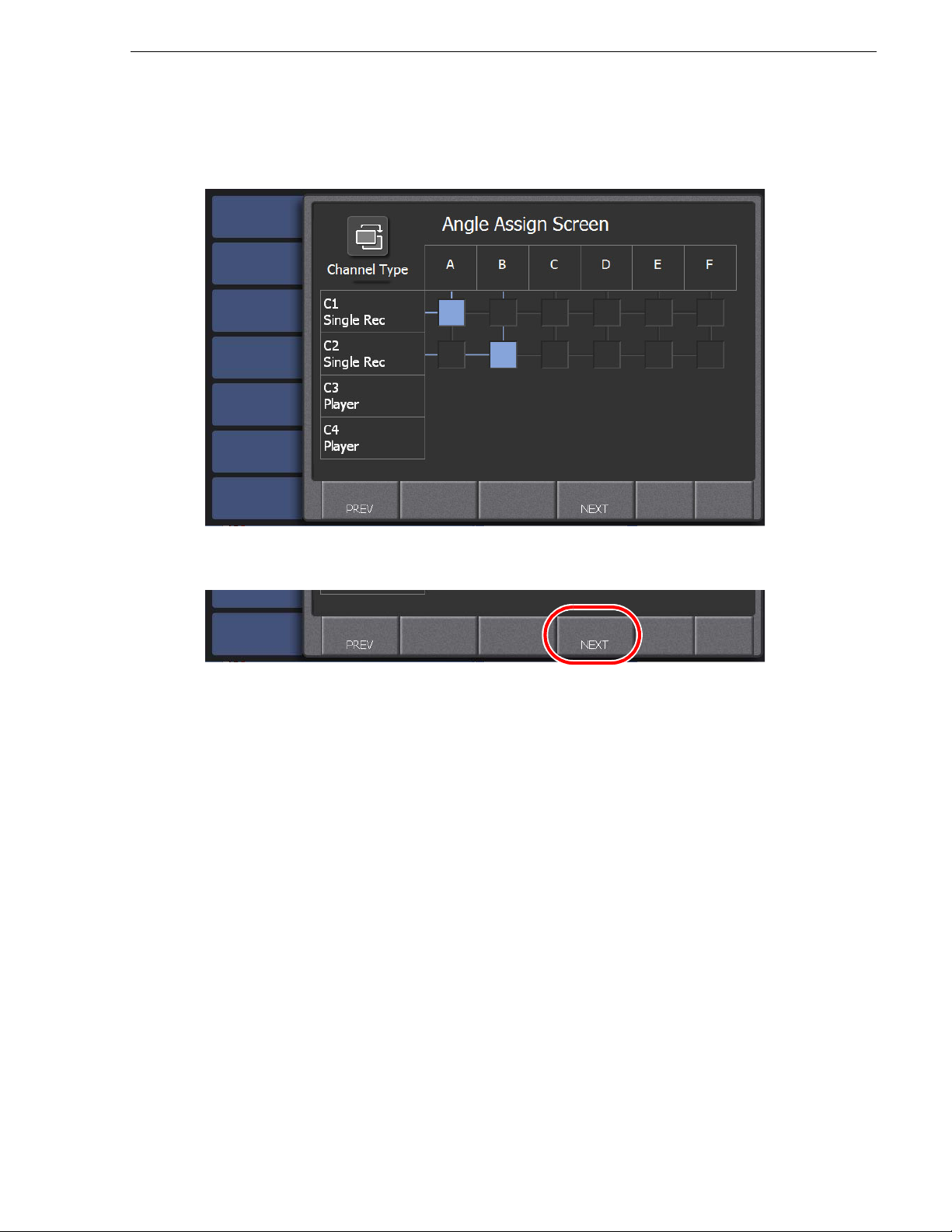
The Angle Assign screen opens. Assign camera angles as follows:
•
Set one camera angle for each of your record channels
7. When camera angles are set, touch NEXT.
NOTE: There are several important restrictions on the channel that is set as
Recorder depending on the codec in use. Be sure to check the release notes of the
K2 Summit Production Client and K2 Dyno Controller before using the product.
.
15 April 2010 K2 Dyno Controller User Manual 29
Page 30
Chapter 2 Starting Up and Shutting Down
8. Assign the P1 or P2 button to the channel that you set as Player. If you want to
perform a LoopRec operation, set the allocation of the record train.
• For more information about the record train and LoopRec setting, see "A
bout
the record train and LoopRec setting" on page 37.
• To perform a LoopRec operation, touch
LOOP REC to turn it on.
• If the LoopRec setting is turned on, you can change the train length allocation
by touching "Length". The maxi mum recording time for each train can be se t by
entering the timecode. Set the length of the Loop Record to match the event's
duration. The Default Factory setting is 3:00:00:00.
• For the player to be used for an on-air live bro adcast, turn on
it to the
P1 button.
P1/PGM and assi gn
NOTE: P1/PGM must be selected.
• For the player to be used for a preview, turn on
P2/PVW and assign it to the P2
button.
• You can assign ei the r one of the
P1 or P2 button to the Player. In addition , you
cannot assign the same button to multiple channels.
• You can specify other vari ous set ti ngs for the K2 Dyno Cont rol l er by t ouch ing
CONFIG. For more information about those settings, see " Settings" on page 163.
NOTE: The Length setti ng only indicat es the maximum re cording time. The actual
lable recording time depends on the remaining space in the Summit.
avai
NOTE: A mark and scene cannot be directly stored to a playlist while LoopRec is
ON. Store
9. Touch
them in a highlight and then store the highlight in a playlist.
START.
• A session for the channel configuration you set is created.
30 K2 Dyno Controller User Manual 15 April 2010
Page 31

Changing the channel configuration for ChannelFlex Suite features
Changing the channel configuration for ChannelFlex Suite
features
Use this procedure if controlling Multi-Cam, 3D/Video+Key, or Super Slo-Mo
channels on the K2 Summit Production Client or K2 Solo Media Server. These
features are a part of the ChannelFlex Suite on the K2 system.
If controlling standard channels with the K2 Dyno Replay Controller, use the
proce
dure "Changing the channel configuration for standard channels" on page 25.
1. Verify that the K2 Summit Production Client or K2 Solo Media Server support
Channel
• K2 system software version 7.2 or higher
• A
• For Super Slo-Mo, HD license insta lled on the K2 system
2. Configure the K2 Summit Production Client or K2 Solo Media Server for the
Cha
Replay Controller. From AppCenter, open Configuration Manager and assign the
channel type. The following example illustrates Multi-Cam Recorder.
Flex Suite features. Requirements are as follows:
ppCenter Elite license installed on the K2 system
Flex Suite channel type that you intend to control with your K2 Dyno
nnel
Select one of the following:
• 3D/Video+Key Player
Video+Key Recoder
• 3D/
• Multi-Cam Recorder
• Super Slo-Mo x2 Reco rder
• Super Slo-Mo x3 Reco rder
Refer to the K2 Ap
15 April 2010 K2 Dyno Controller User Manual 31
pCent
er User Manual for complete procedures.
Page 32

Chapter 2 Starting Up and Shutting Down
1. Start up the K2 Dyno Controller.
For information on how to start up the controller, see "Starting up the K2 Dy no
Controller" on page 24.
When you start up the K2 Dyno Controller for the first time or when you want to
c
eate a session c hanging t he pre vious cha nnel confi guratio n, you need to perfo rm
r
the initial settings at the startup screen. For the default settings, you can set the
settings including the K2 Summit Production Client selection to be used and
channel model setting. Once the initial settings are set, it is not necessary to set
them with
NEW or CONTINUE from the next time.
2. Touch
CONFIGURE.
3. Select the Summit you want to use, and then touch
NEXT.
• Only the online Summit(s) are displayed. The Summit that was used for the last
32 K2 Dyno Controller User Manual 15 April 2010
Page 33

Changing the channel configuration for ChannelFlex Suite features
time appears with a red circle.
• Touch and select a Summit name, and then touch
INFO to display the
information for the Summit.
• If there is a ny se ss ion that is being br oadc as ted, its session name will appear in
"Current Session". If there is any K2 Dyno Controller that is connected to the
Summit, their user name(s) will appear in "Connecting Users".
• Check if the versio ns of App Ce nter a nd K2 Dyno Cli ent so ftware are t he same.
- If the K2 Dyno Controller cannot be started up, their major or minor vers ions are
different.
- If a warning message asking you to choose whether or not to start up the K2 Dyno
Controller is displayed, their patch versions are different.
4. Select "New" from the session list, and then touch NEXT.
• Touching
Touching
LOCAL displays the list of sessions created in the local Summit.
NETWORK displays both the list of sessions created in the local
Summit and the list of sessio ns created in the net work Summit. The session th at
was used for the last time appears with a red circle. You can start a previous
session by touching
• Touch and select a sess ion name, and then touch
NEXT after selecting a session.
INFO to display the infor mation
for the session. You can edit a session name and comment in the information
screen.
15 April 2010 K2 Dyno Controller User Manual 33
Page 34

Chapter 2 Starting Up and Shutting Down
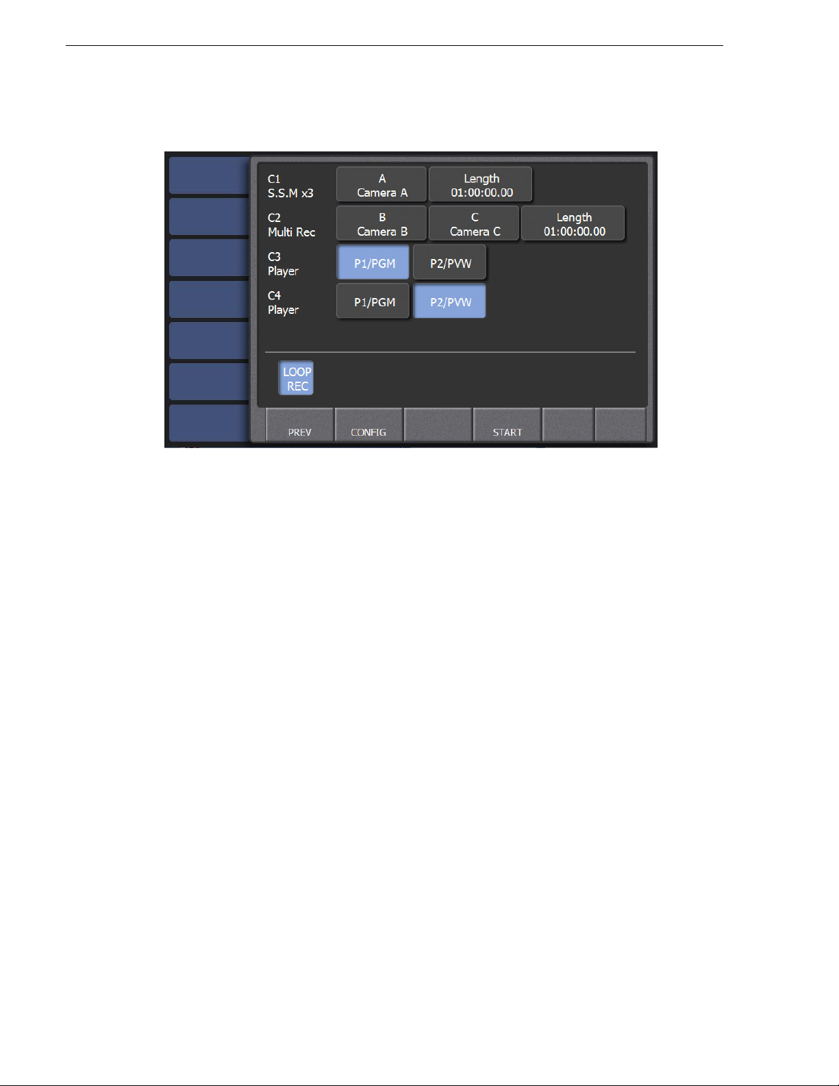
5. Set the use of the channels.
The K2 Dyno Controller detec ts the ch annel t ype curr ently configu red for each
chann
el on the K2 Summit/Soloand provides the corresponding selections.
NOTE: Th e channel ty pe must be first configured on the K2 system, as instructed
rlier in this procedure.
ea
• Assi gn a channel's use by touching the rectangular panels for each channel from
C1 to C4 as follows:
If the K2 system channel type is… Select the following:
3D/Video+Key Recorder Single Rec
3D/Video+Key Player Player
Multi-Cam Recorder Multi Rec
Super Slo-Mo x2 Recorder S.S.M x2
Super Slo-Mo x3 Recorder S.S.M x3
• The assigned camera angle is displayed for a channel that is set as a record
channel.
6. Touch the Angle Assign button.
34 K2 Dyno Controller User Manual 15 April 2010
Page 35

Changing the channel configuration for ChannelFlex Suite features
The Angel Assign screen opens. Assign camera angles as follows:
•
If you assigned channels as Single Rec
Super Slo-Mo channels, set one camera angle for each of those channels
(3D/Video+Key Recorde r)
ch annels or as
.
If you assigned channels a s Multi-Rec (M ulti-Cam) channels, set two camera
•
angles for each of those channels
.
7. When camera angles are set, touch NEXT.
NOTE: There are several important restrictions on the channel that is set as
Recorder depending on the codec in use. Be sure to check the release notes of the
K2 Summit Production Client and K2 Dyno Controller before using the product.
15 April 2010 K2 Dyno Controller User Manual 35
Page 36

Chapter 2 Starting Up and Shutting Down
8. Assign the P1 or P2 button to the channel that you set as Player. If you want to
perform a LoopRec operation, set the allocation of the record train.
• For more information about the record train and LoopRec setting, see "A
bout
the record train and LoopRec setting" on page 37.
• To perform a LoopRec operation, touch
LOOP REC to turn it on.
• If the LoopRec setting is turned on, you can change the train length allocation
by touching "Length". The maxi mum recording time for each train can be se t by
entering the timecode. Set the length of the Loop Record to match the event's
duration. The Default Factory setting is 3:00:00:00. Keep in mind the storage
time used is doubled for each channel when Multi-Rec is used.
• For the player to be used for an on-air live bro adcast, turn on
it to the
P1 button.
P1/PGM and assi gn
NOTE: P1/PGM must be selected.
• For the player to be used for a preview, turn on
P2/PVW and assign it to the P2
button.
• You can assign ei the r one of the
P1 or P2 button to the Player. In addition , you
cannot assign the same button to multiple channels.
• You can specify other vari ous set ti ngs for the K2 Dyno Cont rol l er by t ouch ing
CONFIG. For more information about those settings, see " Settings" on page 163.
NOTE: The Length setti ng only indicat es the maximum re cording time. The actual
lable recording time depends on the remaining space in the Summit.
avai
NOTE: A mark and scene cannot be directly stored to a playlist while LoopRec is
ON. Store
9. Touch
them in a highlight and then store the highlight in a playlist.
START.
• A session for the channel configuration you set is created.
36 K2 Dyno Controller User Manual 15 April 2010
Page 37

Changing the channel configuration for ChannelFlex Suite features
Recording data from the camera A
Recording data from the camera B
:Mark point
Total capacity of the Summit
Recording data from the camera A
Recording data from the camera B
:Mark point
Train length of the record train
About the record train and LoopRec setting
The record train is a method for storing audio/video source data recorded on the K2
Sum
mit Production Client. A single Summit has multiple sessions in which Summit
starts/stops recording. This recording data is called a record train. A record train
contains recording data from different camera angles.
You can select the recording mode from Normal Rec and LoopRec when starting a
ssion. Recording will be stopped in the normal Rec mode when running out of
se
available space on the Summit. Recorded audio/video source data will not be
overwritten. In contrast, when the recording data exceeds the capacity of the record
train in the LoopRec mode, the chronologic ally oldest data will be overwritten by new
data.
There are several restrictions when the LoopRec setting is turned on. For more
formation, see "Restrictions on the LoopRec setting" on page 217.
in
• Normal Rec mode (If the LoopRec setting is turned of f)
Recording will be continued until running out of available space on the Summit.
Recording will be s topped when r unning out o f re cordin g s pace, so the olde st da ta
will not be overwritt en. (Train lengt h of the record t rain cannot be se t in this mode.)
15 April 2010 K2 Dyno Controller User Manual 37
• LoopRec mode (If the LoopRec setting is turned on)
Once the recording data exceeds the train length of the record train, the oldest data
including recorded video or mark points will be overwritt en in chronological or der
to record new data.
Page 38

Chapter 2 Starting Up and Shutting Down
Using the existing sessions
Joining an active session
You can join a session that is currently being broadcasted through the connected
Su
mmit. You can connect two controllers to a single Summit: one f or playback
control operations and the other for editing highlights or playlist.
NOTE: Two controllers joining the same session share the same channel(s).
1. Start up the K2 Dyno Controller.
• For information on how to start up th e controller, see "Starting up the K2 Dyno
Controller" on page 24.
2. Touch JOIN.
• Check if the versi ons of App Center a nd K2 Dyno Cli ent s oftwar e are t he same.
the K2 Dyno Controller cannot be st art ed up, the ir major or minor ver si ons ar e
- If
different.
- If a warning message asking you to choose whether or not to sta rt up the K2 Dyno
Controller is displayed, their patch versions are different.
Recalling the last session
You can restore the last session as it was in case of software termination due to some
obl
ems.
pr
NOTE: If you want to start a previous session, perform Step 4 in "Changing the
channel configuration for standard channels" on page 25 to select and start a
session.
38 K2 Dyno Controller User Manual 15 April 2010
Page 39

Deleting a session
1. Start up the K2 Dyno Controller.
• For information on how to start up th e controller, see "Starting up the K2 Dyno
Controller" on page 24.
2. Touch CONTINUE.
• Check if the versio ns of App Ce nter a nd K2 Dyno Cli ent so ftware are t he same.
- If
the K2 Dyno Controller cannot be sta rt ed up , thei r maj or or minor vers ions are
different.
- If a warning message asking you to choose whether or not to start up the K2 Dyno
Controller is displayed, their patch versions are different.
Deleting a session
You can delete a previous session. If you delete a session, all of the bins and clips saved
as a highlight/playlist will be deleted. If you want to keep data, you must save items in a
library. For more information about libraries, see "Library Function" on page 141.
This section describes how to delete a session from the startup screen. Sessions can
also be deleted in CONFIG. For more information on how to delete a session in
CONFIG, see "Deleting a session" on page 180.
1. Start up the K2 Dyno Controller.
• For information on how to start up th e controller, see "Starting up the K2 Dyno
Controller" on page 24.
15 April 2010 K2 Dyno Controller User Manual 39
Page 40

Chapter 2 Starting Up and Shutting Down
2. Press the Shift button, and then touch DELETE.
3. Select a session you want to delete.
• If you want to delete t he ses si on that was used for the last t ime, to uch
session only
• If you want to delete all the sessions, touch
.
Delete all sessions.
• If you want to delete all the sessions other than the last one, touch
sessions, keep last one
.
Delete last
Delete all
• After selecting the session(s) to delete, return to the startup screen.
40 K2 Dyno Controller User Manual 15 April 2010
Page 41

Shutting down
Shutting down the K2 Dyno Controller
Shutting down
Exit the K2 Dyno Client software to shut down the
1. Touch the
2. Press the
3. Select the action of the K2 Dyno Controller.
CONFIG tab to display the CONFIG screen.
Shift button, and then touch SHUT DOWN.
K2 Dyno Controller
.
•Touch
•Touch
4. Select the option whether or not to close the session that is currently being used.
SHUTDOWN to power off the K2 Dyno Controller.
RETURN TO INITIAL SCREEN to return to the startu p screen.
15 April 2010 K2 Dyno Controller User Manual 41
Page 42
Chapter 2 Starting Up and Shutting Down
• The number of the other
• If you touch
CONTINUE SESSION, only the
K2 Dyno Controller
(s) joining the session is displayed.
K2 Dyno Controller
operating shuts down, while the session currently in use continues.
• If you touch
K2 Dyno Controller
the
CLOSE SESSION, the sessi on curre ntly in use close s, while al l of
s joining the session are shut down.
5. Touch QUIT.
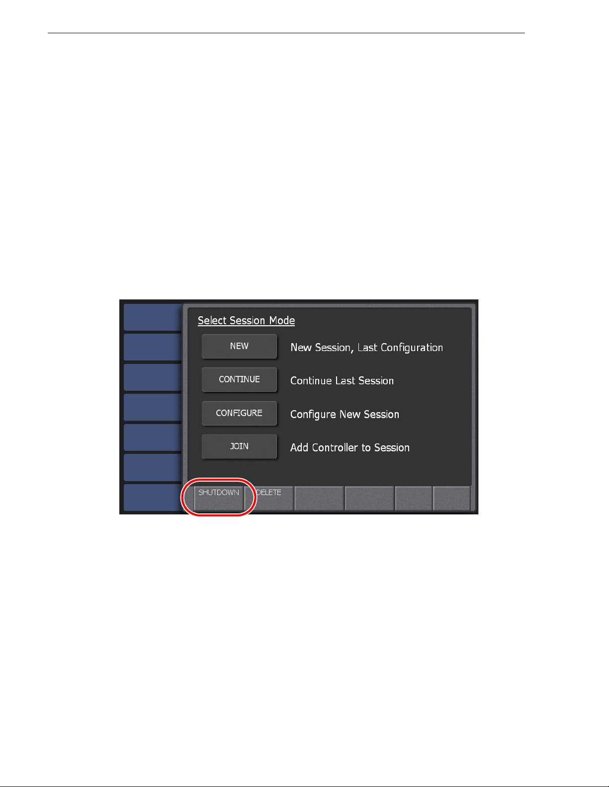
NOTE: If you want to shut down the K2 Dyno Controller at the start up screen, press
Shift button and then touch SHUTDOWN. Then, in the Select Shutdown Mode
the
screen, touch
SHUTDOWN.
Switching to the Windows OS (maintenance mode)
When you want to use the Windo ws OS, such as for adjusting t he clock or s etting the
IP address, exit the K2 Dyno Client software to switch to the Windows OS.
1. At the startup screen, press the
Shift button and then touch SHUTDOWN.
you are
2. Touch
MAINTENANCE MODE.
• The K2 Dyno Client software is closed, and the Windows OS desktop is
di
splayed af ter a restart.
• If you want to start up the K2 Dyno Cli ent software after u sing the Windows OS,
perform a normal shut down operation as with the Windows OS. A message
asking you whether or not you want to return to the K2 Dyno mode appears. If
you choose YES, the K2 Dyn o Client soft ware is starte d after a resta r t.
• If you want to s hut down the K2 Dyno Cont r oll er af ter using the Windows OS,
perform a normal shut down operation as with the Windows OS. A message
asking you whether or not you want to return to the K2 Dyno mode appears. If
you choose NO, the K2 Dyno Controller is shut down.
At the next startup, the K2 Dyno Client software will not be started and the
Windows OS desktop appears to continue the maintenance mode.
42 K2 Dyno Controller User Manual 15 April 2010
Page 43

Chapter 3
Tutorial
This tutorial describes a basic operation workflow to perform a live broadcast using
the K2 Dyno Controller in a specific example of a tennis match, from starting up to
shutting down. In this example, a single K2 Summit Production Client and a single
K2 Dyno Controller are used without connecting the second display for the
description.
This chapter consists of the following :
• "Startup and channel configuration" on page 44
• "Performing a calibration" on page 48
• "Importing keywords" on page 49
• "Live playback and replay" on page 51
• "Switching cameras" on page 53
• "Marking and cueing up" on page 54
• "Storing and playing scenes in a highlight" on page 57
• "Creating and playing a playlist" on page 59
15 April 2010 K2 Dyno Controller User Manual 43
Page 44

Chapter 3 Tutorial
Startup and channel configuration
This section describes how to set the controller for recording with three cameras and
one output channel.
1. Turn on the K2 Summit Production Client.
2. Login K2 Summit Production Client with username (administrat or) and password
(ad
minK2).
3. Start up AppCenter on the K2 Summit Production Client with user name
(a
dministrator) and password (adminK2).
4. Turn on the K2 Dyno Controller.
• The K2 Dyno Client software starts up automatically.
5. Touch
CONFIGURE.
44 K2 Dyno Controller User Manual 15 April 2010
Page 45

Startup and channel configuration
6. Select the Summit you want to use, and then touch NEXT.
7. Select "New" from the session list, and then touch
NEXT.
15 April 2010 K2 Dyno Controller User Manual 45
Page 46

Chapter 3 Tutorial
8. Set the C1 to C3 channels as "Single Rec", set the C4 channel as "P layer", and then
NEXT.
touch
• Assign a channel's use to each channel from C1 to C4 by touching the
angular panels.
rect
• The assigned ca mera angles a re displaye d for the C1 t o C3 channe ls that you set
as Recorde r.
• A channel that is set as "None" can be used for other applications.
9. Touch
P1/PGM of the C4 channel (Player) to turn it on.
• Assign the C4 channel, that you set as Player, to the
46 K2 Dyno Controller User Manual 15 April 2010
P1 button on the controlle r.
Page 47

Startup and channel configuration
10.Confirm the channel configuration, and then touch START.
• A session for the channel configuration you set is created.
15 April 2010 K2 Dyno Controller User Manual 47
Page 48

Chapter 3 Tutorial
Performing a calibration
You can adjust LED brightness of the button, the position of T-Bar, and the idle of
JOG knob to suit your environment or preferences.
1. Press the
2. Perform a calibration.
Shift, Fn, and Next buttons at the same time.
• For more information about calibrations, see "Calibration" on page 199.
48 K2 Dyno Controller User Manual 15 April 2010
Page 49

Importing keyword s
You can import keywords by editing them in advance using the Dyno Keyword editor.
During a broadcast, a keyword can be entered only by touching and selecting a
keyword from the store d data . Import ing ke ywords e dited on a PC in advance allo ws
you to improve your visibility and increase your editing speed.
1. Edit keywords, and then export them to a USB storage device.
• For a tennis match, you may enter keywords such as the number of games/sets
or pl
ayer names. For a baseball match, you may enter keywords such as the
number of innings, hit types, team names, or player names.
• For more information on how to edit keywords, see "Editing and storing
keywords" on page 187.
2. Attach a USB storage device to the K2 Dyno Controller.
• The controller has two USB ports on the front side and four USB ports on the
rear
side.
Importing keywords
3. Touch the
CONFIG tab to display the CONFIG screen.
15 April 2010 K2 Dyno Controller User Manual 49
Page 50

Chapter 3 Tutorial
4. Touch IMP/EXP.
5. Touch and select
Keyword and File, and then touch IMPORT.
50 K2 Dyno Controller User Manual 15 April 2010
Page 51
Live playback and replay
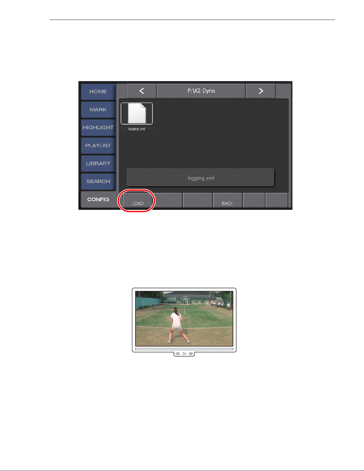
6. Navigate to and select the file you want to import, and then touch LOAD.
• Double-touch to open folders and move down the directory structure.
• T
ouch the bar between
< and > to move up the directory structure.
7. Remove the USB storage device.
Live playback and replay
Now, we begin a live playback. This section describes how to replay the scene in
which a player hits a shot during a tennis match broadcast.
1. Check the camera angle.
• Make sure that the player is showing the video you want to broadcast.
2. Press the
•The Live button will light up in red during a live playback.
Live button.
15 April 2010 K2 Dyno Controller User Manual 51
Page 52

Chapter 3 Tutorial
60%
Plays the scene with the 60% speed.
3.
After the shot, rotate the JOG knob to the left to go back to the point before the ball was hit.
4. Push up the T-Bar to the desired position.
• In standard configur ation, fully pushing up the T-Ba r plays the scene with 100%
speed
. If you want to play it at a slower speed, lower the T-Bar to the desired
position. Play speed is indicated on the HOME screen page.
• Your T-Bar operation w ill immediat ly take effect. For example, you can
decrease the play speed when the ball hits on the line.
• In and Out points are automatically added to the record train with your JOG
knob or T-Bar operations, and they are displayed in the MARK screen.
• To return to the live broadcast, press the
• Press the
Add HL button to store the replayed scene to the highlight.
Live button.
52 K2 Dyno Controller User Manual 15 April 2010
Page 53
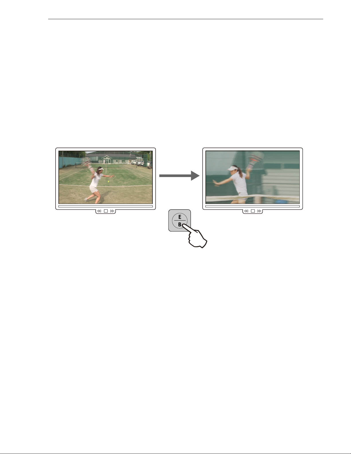
Switching cameras
This section describes how to switch cameras during a live playback and replay.
Switching camera angles
This sectio n describes how to switch the playback source from the A came ra to B
camera as t he time passe s.
Switching cameras
1. Press the
•The
2. Press the
The output displays video from camera B.
• The button for the selected camera lights up in red.
NOTE: The playback speed remains the same ev en if you switch the camera during
a slo
-mo playback. For more information on how to switch camera angles, see
"Switching camera angles" on page 68.
Live button.
Live button will light up in red during a live playback.
B button.
Replaying the same scene again with another angle
This section describes how to replay the same scene with the video from another
camera (camera B).
1. Press the
•The
15 April 2010 K2 Dyno Controller User Manual 53
Live button.
Live button will light up in red during a live playback.
Page 54

Chapter 3 Tutorial
2. Replay the scene.
3. Press the
• The controller will go back to the In point of the scene, and replay t he scene with
•Press
•If the
NOTE: The playback speed remains the same ev en if you switch the camera dur ing
a slo-
NOTE: If the playback i s stopped such a s moving the T-Bar back to the 0% po sition
ter replaying a scene in step 2, the controller cues up to the In point of the scene
af
after the operation in step 3.
Fn button, and then press the B button.
fferent angle.
a di
Fn button to cancel the Fn function when it is in Fn mode.
Fn button is not pressed, only the camera angle is changed without
rewinding back to the In point.
mo playback.
NOTE: If you perform the step 3 again when pl aying the record t rain, the controller
go back to the playback point prior to switching the camera angles instead of
will
going back to the scene's In point.
Marking and cueing up
You can cue-up and replay a scene that was previously marked during the live
playback.
This section describes how to mark a scene at a point just before a serve, cue up and
re
play the scene in which an ace was successfully served, and additionally enter
logging information to help you search the scene easily afterwards.
1. Begin a live playback.
54 K2 Dyno Controller User Manual 15 April 2010
Page 55

Marking and cueing up
2. Press the Add Mrk button at a scene in which the player initiates a serve.
• To view the marked scene informati on, switch the d isplay to the MARK scr een.
A new ent
ry is made every time you press the Add Mrk button.
NOTE: In addition to marking sce nes during live playback, the controller is
apabl
e of marking new scenes while output is replaying or playing a playlist.
c
3. After the ace, press the
Previous button.
15 April 2010 K2 Dyno Controller User Manual 55
Page 56

Chapter 3 Tutorial
• In addtion, the Out point of a scene i s s et when the Previous button is pressed,
while its In point is set when the Add Mrk button is pressed. The screen
automatically switches to the MARK screen when the
Previous button is
pressed.
• If you want to select a de sired mark, eith er touch the mark in the MARK screen
and press the
Cue Up button, or use the Previous/Next button to select the
mark.
4. Press the Play button.
• You can also perform a slo-mo playback with the T-Bar.
• T
o return to the live broadcast, press the
Live button.
• Press the
Add HL button to store the replayed scene to the highlight.
5. Select a mark, and then touch the property panel.
6. Enter logging information.
• For information on how to en ter loggi ng inform ation, se e "E
information" on page 93.
ring the logging
nte
• If there is no time for entering detailed information, you can enter only the rating
by pressing the [Ctrl] + [Space] keys with a keyboard connected.
About the cursor colors
The K2 Dyno Controller shows the item stat us with cursor c olors. The cursor appears
as an outline around a highlight clip or other item. The cursor colors are common in
all screens . The meanings of the cursor colors are as follows:
• Blue cursors indicate tha t the item is selected.
• W
hite cursors indicate th at the item is s elected addi tionally.
• Green cursors indicate that the item is being replayed.
• Red cursors indicate that the In point of the item is being cued up.
56 K2 Dyno Controller User Manual 15 April 2010
Page 57

Storing and playing scenes in a highlight
• Dashed cursors indicate that the item is being cued up or played in another playback channel.
Storing and playing scenes in a highlight
You can store important scenes to a highlight. For example, stored highlight scenes
can be later added to a playlist.
A bin provides boxes called shot boxes which allow you to save highlight items by
addi
ng items to these boxes.
1. Touch and select a mark or scene you want to store to the highlight.
• The property panel shows the currently selected item.
2. Touch the
• The current bin is expanded. By default, "Bin1" is expanded.
3. Touch the shot box to which you want to store the selected scenes/marks.
• You can manage the highlight items accor ding to the positions of the shot boxes;
for example, by coll ecting t he Player A s cenes t o the lef t side an d collect ing the
Player B scenes to the right side.
HIGHLIGHT tab to display the HIGHLIGHT screen.
15 April 2010 K2 Dyno Controller User Manual 57
Page 58

Chapter 3 Tutorial
• You can also press the Add HL button to store a scene. For button operations,
the shot box to store the scenes cannot be specified.
4. Touch and select the highlight item you want to play.
• When the HIGHLIGHT screen is displayed, you can also press the
button to select a previous/next item.
Next
5. Press the
Cue Up button, and then press the Play button.
• You can also perform a slo-mo playback with the T-Bar.
Previous/
• If you selected a hig hlight item by pres sing the
Previous/Next button in Step 4,
the controller will start a cueing up operation as soon as you select ed the
previous/next item.
58 K2 Dyno Controller User Manual 15 April 2010
Page 59

Creating and playin g a playlist
Button operation
This section describes how to store an item as an event of the playlist and play it all
the way from the beginning. For more information on how to edit transitions and
audio, see "Editing a Playlist" on page 117.
1. Select an item you want to store to the playlist.
• The property panel shows the currently selected item outlined in blue.
Creating and playing a playlist
2. Touch the
event box, which is indicated by the red outline in the following illustration.
Press the Add PL button.
PLAYLIST tab to display the PLAYLIST screen, and then touch the
15 April 2010 K2 Dyno Controller User Manual 59
Page 60

Chapter 3 Tutorial
Button operation
3. Repeat Steps 1 and 2 to store items as necessary.
4. Touch the f irst event, and then press the
Press the PL butto
n one, two, or three t imes as ne cessary to cue up th e s ta rt poi nt ,
Cue Up button.
as follows:
• If you are not on the PLAYLIST screen, pressing the PL button displays the
PLAYLIST screen.
• If you are in the PLAYLIST screen and there is no playback pointer in the
playlist, pressing the PL button moves the playback pointer to the point where
the playlist stopped its playback.
• If you are in the PLAYLIST screen and there is a playback pointer in the playlist,
pressing the PL button cues up to the beginning of the playlist.
5. Press the
Play button.
• You can also perform a slo-mo playback with the T-Bar.
• P
ressing the
Previous/Next button during a playback begins a playback of the
previous/next event.
• Pressing the
Previous button after pressing the Fn butto n cues up to a poi nt just
before the In poi nt of the e vent in pla yback and pe rforms a pla yback pass ing the
In point. Pressing the forwared
Previous/Next button after pressing the Fn
button cues up to a point just before the Out point of the event in playback and
performs a playback passing the Out point.
60 K2 Dyno Controller User Manual 15 April 2010
Page 61

Chapter 4
Playback
This chapter consists of the following :
• "Components in the HOME screen" on page 62
• "Starting and stopping a recording" on page 65
• "Replay" on page 66
• "Switching cameras" on page 68
• "Audio level settings" on page 72
• "On-air preview mode and multi-channel mode" on page 73
• "Transferrin g the channel control" on page 80
• "Checking the contents of the Recycle Bin (trash box)" on page 81
• "Error list display" on page 83
15 April 2010 K2 Dyno Controller User Manual 61
Page 62
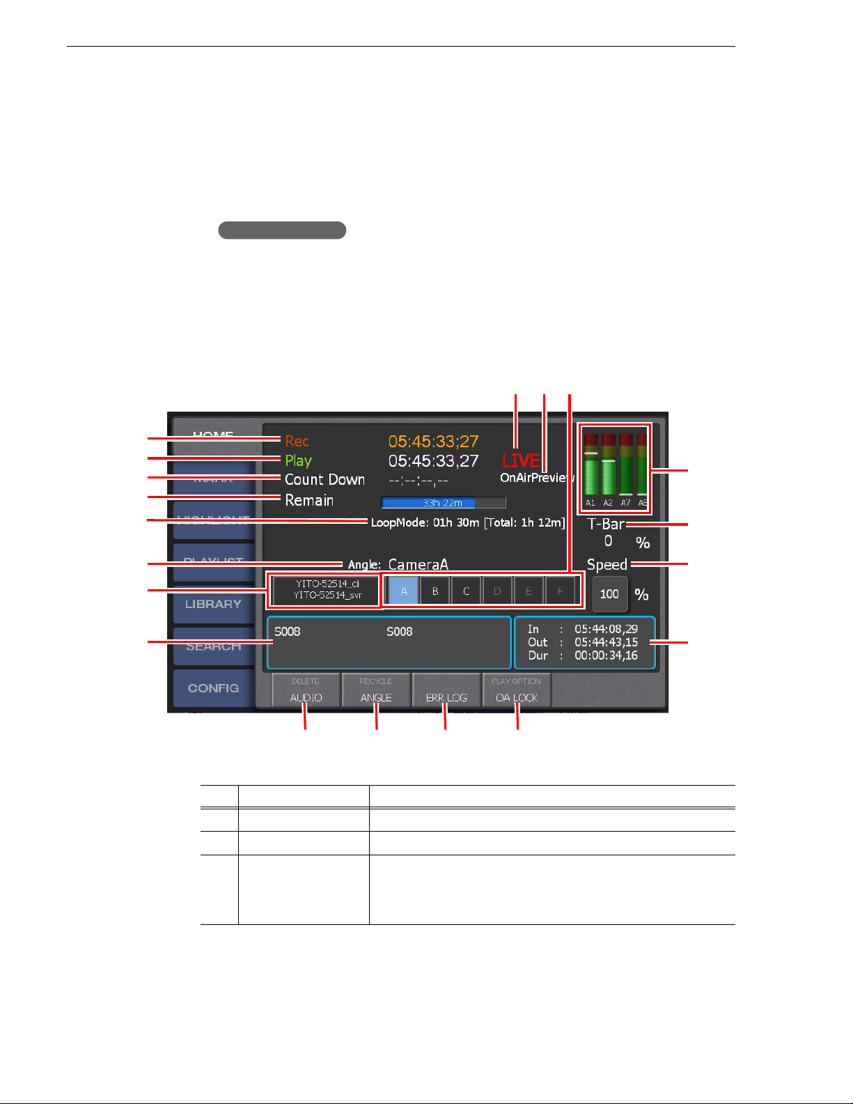
Chapter 4 Playback
Button operation
(1)
(2)
(3)
(4)
(7)
(8)
(9) (11)
(12)
(13)
(14)
(15)
(16) (17) (19)
(5)
(6)
(10)
(18)
Components in the HOME screen
The HOME screen is a scr een for vi ewing basi c informat ion su ch as the ti mecode fo r
the recording data, playback item rem aining time, and selected camera.
1. Touch the
Press the
HOME tab.
Shift button, and then press the Local button.
• The HOME sc reen appears. For more information abou t the indicati on
meanings and individual panel functions, see the following table. To perform
functions (indicat ed by t he shaded area in the t able) th at are di splayed at the t op
of the menu panels shown at the bottom of the screen, press the
Shift button, and
then touch the de sired menu panel. For more informatio n on how to use the
button, see "About Shift button operations" on page 21.
Shift
62 K2 Dyno Controller User Manual 15 April 2010
No. Name Function
(1) Rec
(2) Play
(3) Count Down
Shows the timecode for the recording data.
Shows the timecode for the playback data.
Shows the remaining time when playing a highlight or playlist. The
color of the timecode changes depending on the playback point. It is
shown in red while cueing up, shown in yellow while playing a
pre-roll/post-roll, and shown in green while play ing an item.
Page 63

No. Name Function
(4) Remain
Shows the free space in the Summit with the blue progress bar and time
display, and shows its usage with the gray progress bar.
* If the recording bit rates are different for each recording channel, the
Summit's free space displayed in "Remain" on the K2 Dyno
Controller and the free space value di splayed in App Center of the
Summit may not match.
This is caused because App Center displays free space for each
ann
ch
the average bit rate between the recording channels and displays it as
a single value.
If you want to check the remaining recordable time from the
"Remain" displa y on your K2 Dyno Controller, calculate it by
dividing the free space time by the number of the recording channels.
(5) Train length of the
record train
This is displayed only if the LoopRec setting is turned on.
The train length for the currently se lected camera angle and the train
ngth for all the angles are displayed.
le
* If the recording bit rates are different for each recording channel, the
train length for all the angles (total loop length) is not displayed as
the value totaling the train lengths that are set for the individual
recording channels.
This is due to the fact that the accurate total loop length cannot be
b
tained by just totaling the train le n gths of the ind iv idu a l cha nn els
o
and that calculation including the bit rates is required in order to
calculate an accurate value.
(6) Camera name
(7) Controller name/
Summit name
The camera name that is currently selected is displayed.
The top row shows the user name currently using the K2 Dyno
Controller and the bottom row shows the hostname of the K2 Summit/
Solo currently connected. If you want to c hange a K2 Sum mit/Solo t o
be accessed, return to the startup screen. For more information, see
"Changing the ch a nn el configuration f or standard channe ls " on
page 25.
(8) Property panel
Shows the number and name of the selected item. The item number is
prefixed with an alphabet indicating the item type:
• "M" indicates a mark with only an In poi nt .
"
S" indicates a scene with an In and an Out point.
•
• "H" indicates a highlig ht.
• "E" (event) indicates that the item is stored in a playlist.
• "P" indicates a playlist.
The property panel also displa ys any additional logging information
u enter for the selected item.
yo
(9) Status
Shows the playback status:
• LIVE: Performing a live playback.
OG: Performing a rewind or fast forward operation with the JOG
• J
knob.
• PLAY: Playing an item, such as a highlight or playlist.
• VARIABLE: Playing an item with the T-Bar operation.
• STOP: The playback is stopped.
• CUED: Cued up and stopped.
• MM: Performing a reverse playback to the target position.
Components in the HOME screen
el while the K2 Dyno Controller calculates free space based on
15 April 2010 K2 Dyno Controller User Manual 63
Page 64

Chapter 4 Playback
No. Name Function
(10) Cha nnel mode
Shows the current channel mod e.
• OnAirPreview: On-air preview mode
• M
For more information about the on-air preview and multi-channel
o
des, see "On-air preview mode and multi-channel mode" on
m
page 73.
(11) Camera angle
(12) Aud io level indicator
Shows the selected camera angle for the live playback.
Shows the audio level and audio track number of the player for the
current playback.
The audio level for the audio track yo u selected in "PANEL" on the
CONFIG sc
track to display, see "Panel settings (the confirmation dialog setting,
audio level meter setting)" on page 173.
(13) T-Bar
(14) Speed
Shows the T-Bar position.
Shows the playback speed.
You can specify the playback speed by touching the panel.
(15) In/Out/Dur panel
Shows the selected item's timecodes of the In and Out points, and its
duration.
(16) DELETE
AUDIO
Deletes the selected item.
Displays the audio level setting screen. For more information, see
"Audio level settings" on page 72.
(17) RECYCLE
Displays the "Recycle Bin" (trash box). For more information, see
"Checking the contents of the Recycle Bin (trash box)" on page 81.
ANGLE
(18) ERR LOG
Displays the camera angle selection screen.
If an error occurs while operating the K2 Dyno Controller, a warning
mark appears to the left of the panel. Touch this to check the error
description. For more information, see "Error list display" on page 83.
(19) PLAY OPTION
Displays the play option setting screen. For more information about
the settings, see "Play option settings" on page 185.
OA LOCK/
OA UNLOCK
Turns on or off the on-air lock.
While the lock is enabled, "ON-AIR LOCK" is displayed at the cent er
the screen disabling operations to change the playback status, such
of
as cueing up and replaying of the item, operations with the T-Bar or
JOG knob, and ca m era angle cha nges.
ultiChannel: Multi-channel mo de
re
en is displayed. For inform ation on how to set th e audio
NOTE: The HOME tab shows a warning or caution mark when the following
situations occur.
ex: When an error occurs while operating the K2 Dyno Controller
- Warning mark on the right: When an error occurs while operating the K2 Dyno
64 K2 Dyno Controller User Manual 15 April 2010
Page 65

Controller
- Warning mark on the left: When the Summit is low on free space (10 mins x the
number of the recording channels)
- Ca ution m ark on the left : When the Su mmit is low on free sp ace (3 0 min s x the
number of the recording channels)
Starting and stopping a recording
Live playback
The data recorded in the Summit is played with t he minimum time difference.
1. Check the camera angle.
Starting and stopping a recording
2. Press the
• The recording begins, and "LIVE" is displayed in the HOME screen.
•Th
NOTE: If you touch
operations to change the playback status, such as cueing up and replaying of the
item, operations with the T-Bar or JOG knob, and camera angle changes are
disabled, allowing for prevention of improper operations during a broadcast.
To turn off the on-air lock, either touch OA UNLOCK or press the Fn button and
then press the
Live button.
e
Live button will light up in red during a live playback.
OA LOCK that is displayed at the bottom of the HOME screen,
Stop button.
About the pseudo live mode
The system internally ends the live playback mode when the
pressed during a live playbac k, howev er, it co ntinue s to p lay the da ta bein g rec orded
with the minimum time dif fer en ce as with a live playb ack . Thi s c ondi tion is referred
to as the "pseudo live mode". Since the system is not internally in the live playback
mode during the pseudo live mode, you must note th at you cannot cr eate a scene wit h
any JOG knob, T-Bar, or
turned on in "CLIP" of the CONFIG screen.
In order to distinguis h whether the cur rent mode is the normal live pl ayback mode or
the p
seudo live mode, check the following indications:
• The word "LIVE" displayed in the HOME screen
15 April 2010 K2 Dyno Controller User Manual 65
Previous/Next button operation even if Auto Scene is
Play or In button is
Page 66

Chapter 4 Playback
Stopping a recording
Normal live playback mode: The word "LIVE" is shown in red.
Pseudo live mode: The word "LIVE" is shown in white.
• The button LED indications
Normal live playback mode: The
Pseudo live mode: The
illuminat ed in green.
If you want to return to the normal live playback mode from the pseudo live mode,
press the
The data recording is stopped. It does not stop the item playback.
Live button.
Live button is illuminated in red while the Play button is
Live button is illuminated in red.
1. Touch the
• The CONFIG screen appears.
2. Press the
3. Touch
CONFIG tab.
Shift button, and then touch REC STOP.
YES when a confirmation message is displayed.
Replay
A replay is an operation to go back and play a scene again when an important scene
was found during a live playback. You can use the following met hods: to search and
replay a scene with the JOG knob or to mark a scene in advance for cueing up and
replaying it as necessary .
This section describes how to go back and replay a scene using the JOG knob. For
rmation on how to replay a scene by marking and cueing up, see "Marking and
info
cueing up" on page 87.
1. Begin a live playback.
2. When an important scene is found, rotate the JOG knob to the left
66 K2 Dyno Controller User Manual 15 April 2010
Page 67

(counter-clockwise) to go back to the beginning of the scene.
3. Play the scene with the T-Bar.
• Fully pushing up the T-Bar plays the scene with the 10 0% speed. If y ou want to
pl
it at a slower speed, move and fix the T-Bar in a desired position.
ay
• If Super Slo-Mo, posi tioning t he T-Bar i n the middle pl ays at t he Super Slo -Mo
speed. For example, if Super Slo-Mo x3, the middle position speed is 33%.
• The speed is indicated on the screen.
Replay
• Pressing the
Play button plays the scene with the 100% speed.
• If you operate t he JOG k nob or T-Bar , In and Ou t poin ts are a dded to th e recor d
train and they are displayed in the MARK screen.
15 April 2010 K2 Dyno Controller User Manual 67
Page 68

Chapter 4 Playback
Button operation
Switching cameras
Switching camera angles
This section describes how to switch cameras during a live playback and replay.
NOTE: You can apply effects (Flying M/E), such as dissolves, to the video when
playing a scene or switchi ng cameras d uring a pl aylis t or hig hlight playbac k. To
re
enable Flying M/E, press the
keyboard is connected, you can enabl e/disable Flying/ ME by pressing the [F1] key.
For more information on how to set the Flying M/E setting, see"Mix effect
settings" on page 171.
1. Begin a live playback.
2. At a scene in which you want to switch camera angles, from the HOME screen
touc
ANGLE to display the camera angle selection screen, touch a camera name
h
panel, and then touch
Shift button and then press the M/E button. If a
SELECT.
Press the
• The button for the selected camera lights up in red.
A/B/C button or press the D/E/F button after pressing the Shift button.
68 K2 Dyno Controller User Manual 15 April 2010
NOTE: The playback speed remains the same ev en if you switch the camera dur ing
a slo-
mo playback.
Replaying the same scene with another angle
You can go back and replay a scene from the scene's In point when you switch
cameras.
Page 69

1. Replay the scene.
Button operation
About play speed
2. Press the
3. At a scene in which you want to switc h camera angles , touch
camera angle selection screen, touch a camera name panel, and then touch
SELECT.
Press the
• The controller will go back to the In point of the scene, and replay th e scene with
a different angle.
NOTE: The playback speed remains the same ev en if you switch the camera during
a slo-
Fn button.
ANGLE to display the
A/B/C button or press the D/E/F button after pressing the Shift button.
mo playback.
NOTE: If the playback i s stopped such a s moving the T-Bar back to the 0% pos ition
ter replaying a scene in step 1, the controller cues up to the In point of the scene
af
after the operation in step 3.
NOTE: If you perform the steps 2 to 3 again when playing the record train, the
oller will go back to the playback point prior to switching the camera angles
contr
instead of going back to the scene's In point.
About play speed
If you use the K2 Summit/Solo ChannelFlex features and have Super Slo-Mo clips,
you should consider the K2 Dyno cont roller’s int ernal play s peed as well a s the speed
that is displayed when you view the video, and how this interacts with your use of
controls. Play speed behavior is as follows:
15 April 2010 K2 Dyno Controller User Manual 69
Page 70

Chapter 4 Playback
Play button behavior
When you press the Play button, play speed behaves as follows:
Internal speed Displayed speed
Normal clip 100% 100%
Super Slo-Mo x2 clip 100% 50%
Super Slo-Mo x3 clip 100% 33%
T-bar behavior
When you use the T-bar, play speed behaves as follows:
Lever position Internal speed Displayed speed
Normal clip Maximum 100% 100%
Minimum 0% 0%
Super Slo-Mo x2 clip Maximum 200% 100%
Minimum 0% 0%
Super Slo-Mo x3 clip Maximum 300% 100%
Minimum 0% 0%
Flying M/E behavior
Flying M/E between Super Slo-Mo clips and normal clips behaves as follows:
Play Mode
Keep internal speed
Super Slo-Mo x3 clip
Internal speed 100%
Display speed 33%
Variable Mode
Super Slo-Mo x3 clip
Internal speed 100%
Display speed 33%
<==================> Super Slo-Mo x3 clip
Internal speed 100%
Display speed 100%
Keep display speed
<==================> Super Slo-Mo x3 clip
Internal speed 33%
Display speed 33%
70 K2 Dyno Controller User Manual 15 April 2010
Page 71

Angle switching behavior
When you switch camera angles, play speed behaves as follows:
Play Mode
Keep internal speed
Super Slo-Mo x3 clip <==================> Super Slo-Mo x3 clip
About play speed
Internal speed 100%
Display speed 33%
Variable Mode
Super Slo-Mo x3 clip
Internal speed 100%
Display speed 33%
LIve Mode
Super Slo-Mo x3 clip
Internal speed 300%
Display speed 100%
Internal speed 100%
Display speed 100%
Keep display speed
<==================> Super Slo-Mo x3 clip
Internal speed 33%
Display speed 33%
Keep display speed
<==================> Super Slo-Mo x3 clip
Internal speed 100%
Display speed 100%
15 April 2010 K2 Dyno Controller User Manual 71
Page 72

Chapter 4 Playback
(1)
(2)
(3)
(4)
(5)
(7)(6)
Audio level settings
You can adjust the audio level for each channel and audio track, respectively.
1. Touch
• The audio level setting screen appears. For information about the indication
AUDIO in the HOME screen.
meanin
gs and individual panel functions, see the following table.
72 K2 Dyno Controller User Manual 15 April 2010
Page 73

No. Name Function
(1) Channel/Angle
selecti
on
(2) Audio track selection
(3) Audio level indicator
(4) Display All Tracks
(5) Level
(6) Mute
(7) RESET
For Recorder channels, select the came ra angle for which you are
setting the audio. For Player channels, select the channel for which you
are setting the audio. By default, the player of the operation target
channel is selected.
Select the audio track(s) to be se t. Touching ALL switches betwee n all
selected and all deselected. Multiple selection is also available.
The audio level for each audio track is shown at the bottom.
Shows the audio level and audio track number of the player for the
current playback.
The audio level for the audio tra ck you selected in "PANEL" on the
CONFIG scre en is d ispl aye d. For info rmat ion on ho w to s et th e audi o
track to display, see "Panel settings (the confirmation dialog setting,
audio level meter setting)" on page 173.
Turn this on to display the audio level for all of the audio tracks.
Set an audio level. Touching up/down Previous/Next buttons adjus ts
the audio level by 1 dB. You can also enter a value directly by touching
the audio level panel. The value can be set within a range of 20 to -40
dB.
Mutes the audio. You can mute the audio without changing the set
values even when the audio levels for the selected channels or audio
tracks are not the same.
Restores all the audio levels for the selected audio track(s) to 0 dB.
On-air preview mode and multi-channel mode
2. After editing the information by touching each panel, touch BACK.
On-air preview mo de and multi-channel mode
If two or more channels are assigned as players, you can operate the controller with
the option of the on-air preview and multi-channel modes.
The on-air preview mode is a mode to use one channel as a program channel (a
chann
el for an on-air broadcast) while using another channel as a preview channel.
While in the multi-channel mode, you can s witch operation targets for multiple
chann
els or synchronize the playback status for multiple channels.
Playback operations in the on-air preview mode
This section describes a flow of playback operations in the on-air preview mode.
NOTE: You must assign channels to be used as program and preview channels to
PGM (P1) and PVW (P2) buttons beforehand. For more information, see
the
"Record train length allocation settings" on page 164.
15 April 2010 K2 Dyno Controller User Manual 73
Page 74

Chapter 4 Playback
Program Channel Preview Channel
1. In the HOME screen, make sure that the controller is in the on-air preview mode.
• If the controller is in the on-air preview mode, the screen shows
irPreview".
"OnA
• If the contr oller is in the multi-cha nnel mode, the screen shows " MultiChannel".
Switch to the on-air preview mode by pressing the
pressing the
Shift button.
PGM or PVW button after
• The program channel becomes the target for operations.
2. Begin a live playback in the program channel.
74 K2 Dyno Controller User Manual 15 April 2010
Page 75

Playback operations in the on-air preview mode
Button operation
3. Touch PreviewCtrl to turn it on in the play o ptions.
Press the P2 button.
•The
P2(PVW) and Take button light up in green while the preview control is
turned on.
• When you turn on th e pr eview control, the pre view channel becomes the t ar get
for all of the operations, such as operations with the
Live button, T-Bar, or JOG
knob. For more informat ion about the play options , see "Play optio n settings" on
page 185.
15 April 2010 K2 Dyno Controller User Manual 75
Page 76

Chapter 4 Playback
Program Channel Preview Channel
Program Channel Preview Channel
4. Locate the scene to be broadcasted on air in the preview channel.
• Locate and put the scene in standby, performing operations such as rewinding
th
e live video in the preview channe l, or cueing up to the beginni ng of a playlist
or highlight using the JOG knob. For more information about the detailed
operation procedures, see the chapter for each function.
5. Press the
Take button.
• The video that is put into standby in the preview channel is loaded and played
in the program channel. Even if the video is currently stopped in the preview
channel, i t will be in a playback sta te at the same time as the
pressed.
• Pressing the
Take button after pressing the Fn button while the preview control
is turned on switches video between the preview and program channels. The
current video for the program channel is loaded and played in the preview
channel at the same time as the video on standby in the preview channel is
loaded and played in the program channel.
Take button is
76 K2 Dyno Controller User Manual 15 April 2010
Page 77

Switching the operation target channel in the multi-channel mode
6. Repeat steps 4 and 5.
• To turn off the prev iew co ntrol, e ither p ress the
P1 button or touch PreviewCtrl
from the play options to turn it off.
Switching the operation target channel in the multi- channel mode
This section describes how to switch the operation target channel in the multi-channel
mode.
NOTE: You must assign two channels to be mainly u sed to the
beforehand. For more information, see "Record train length allocation settings"
on page 164.
NOTE: You can switch among more than two channels if you operate the controller
an expansion screen. For more information, see "Play option settings" on
using
page 208.
1. In the HOME screen, make sure that the controller is in the multi-channel mode.
P1 and P2 buttons
• If the controller is in the multi-channel mode, the screen shows "MultiChannel".
I
f the controller is in the on-air preview mode, the screen shows
•
"OnAirPreview". Switch to the multi-channel mode by pressing the
PVW button after pressing the Shift button.
2. Press the
P1 or P2 button.
PGM or
• The operation target channel is switched to the P1 or P2 channel.
• T
he button for the selected channel lights up in red.
15 April 2010 K2 Dyno Controller User Manual 77
Page 78

Chapter 4 Playback
Fill video
Key video
Synchronizing playback status for multi-channel (Gang) mode channels
You can synchronize the playb ack status for multiple cha nnels by turning on the Gang
mode while in the multi-channel mode.
For example, this function can be used when you want to play video from multiple
ca
mera angles synchronizing them or when you want to show difference in speed
between two ski jumpers by synchronizing the video of the player A and player B
from the start point.
It can also be used when you want to apply a mask-like effect by simultaneously
ing Key video with transparency information and Fill video you want to
play
composite to the Key video.
This section describes ho w to play Key and Fill video simul taneously usin g the Gang
mode.
OTE: You must assign two channels to be mainly use d to the
N
beforehand. For more information, see "Record train length allocation settings"
on page 164.
NOTE: You must store clips you want t o use as Key and Fill video t o t he hi ghl ight
rehand. For more information on how to use the HIGHLIGHT screen, see
befo
"Highlight" on page 99.
NOTE: You can synchronize more than two c hannels i f you opera te the con troll er
an expansion screen. For more information, see "Play option settings" on
using
page 208.
P1 and P2 buttons
78 K2 Dyno Controller User Manual 15 April 2010
Page 79

Synchronizing playback status for multi-channel (Gang) mode channels
1. In the HOME screen, make sure that the controller is in the multi-channel mode.
• If the controller is in the multi-channel mode, the screen shows "MultiChannel".
f the controller is in the on-air preview mode, the screen shows
• I
"OnAirPreview". Switch to the multi-channel mode by pressing the
PVW button after pressing the Shift button.
2. Press the
P1 button.
PGM or
• The operation target channel is switched to the P1 channel.
3. Display the HIGHLIGHT screen, and cue up the item you want to use as the Key
vi
o.
de
• For more informati on about th e detailed operation pr ocedures, s ee "S
toring and
playing scenes in a highlight" on page 57.
4. Adjust the playback start point of the Key video using the JOG knob.
5. Press the
P2 button.
• The operation target channel is switched to the P2 channel.
6. Display the HIGHLIGHT screen, and cue up the item you want to use as the Fill
vi
o.
de
7. Adjust the playback start point of the Fill video using the JOG knob.
• Adjust it acc ording to the playb ack start point o f t he Key video you adjuste d i n
ste
p 4.
8. Press the
P1 and P2 buttons at the same time.
• The controller enters the Gang mode and the
9. Press the
Play button.
P1 and P2 buttons light up in red.
• The playback status of the Key and Fill video is synchronized.
15 April 2010 K2 Dyno Controller User Manual 79
Page 80

Chapter 4 Playback
• You can also perform a slo-mo playback with the T-Bar.
• To exit the Gang mode, press the
NOTE: While in the Gang mode, you can press the Cue Up button to perform a
cueing up operation for all the channels of the Gang mode. In this case, the angle
data to be cued up is the angle that is set as primary in "PLAY1" on the CONFIG
screen.
P1 or P2 button.
Transferring the channel control
You can transfer the channel control from K2 Dyno Controller to other application
program, or obtain the abando ned channel contr ol. For exampl e, you c an tra nsfer the
channel control to the other program after you cued up to any scene using the K2
Dyno Controller. The other application program can obtain the channel control and
continue the edit operation (playback, etc.).
This section desc ribes the operati on of transferrin g the P1 channel contr ol with the K2
Director product. T his is a Grass Vall ey applic ation. Conta ct your Gr ass Valley
Dyno
representative for availability.
NOTE: Th is function cannot be used during the preview c ontrol of the on-air
iew mode.
prev
Offering the channel control (Offer mode)
1. Cue up to any scene using the K2 Dyno Controller.
• Locate and put the scene in standby, performing operations such as rewinding
the l
ive video with the JOG knob, or c uei ng up to the beginning of a pl ay li st or
highlight. For more i nformation about t he detailed op eration procedu res, see the
chapter for each function.
2. Press the
• The controller enters the Offer mode and no playback operation for the P1
• You can obtain th e channel contro l again with the K2 Dyno Controller while t he
NOTE: When this function is used in the multi-ch annel mode, you can offer the
nnel contro l assigned to the
cha
any scene in step 1, and press the
Fn button, and then press the P1 button.
chann
el is allowed in the K2 Dyno Control ler. The
and it chan ges to flash in red after the operation to obtain the control is
performed by Dyno Director.
P1 button flashes in yellow.
P2 button. Press the P2 button and then cue up to
Fn button and then press the P2 button in step 2.
P1 button flashe s in ye llow,
80 K2 Dyno Controller User Manual 15 April 2010
Page 81

Obtaining the channel control
If the other appli cation program su ch as Dyno Direc tor abandons t he channel c ontrol,
P1 button flashes in yellow. Wh ile flas hing in yell ow, you can obtai n the channe l
the
control with the K2 Dyno Controller.
Obtaining the channel control
1. Press the
•The
channel.
NOTE: Press the
control assigned to the
Fn button, and then press the P1 button.
P1 button lights up in green allowing playback operations for the P1
Fn button, and then press the P2 button to obtain the channel
P2 button in the multi-channel mode.
Checking the contents of the Recycle Bin (trash box)
The item deleted in each screen is moved to the Recycle Bin.
1. Press the
Shift button in the HOME screen, and then touch RECYCLE.
15 April 2010 K2 Dyno Controller User Manual 81
Page 82

Chapter 4 Playback
(2)
(3) (4) (6)
(1)
(5)
• The Recycle Bin appears. For more information about the indication meanings
and individual panel functions, see the table below. To perform functions
(indicated by the shaded area in the table) that are displayed at the top of the
menu panels shown at the bottom of the screen, press the
touch the desired menu panel. For more information on how to use the
Shift button, and the n
Shift
button, see "About Shift button operations" on page 21.
• Some of the items are different depending on the item types displayed in the
trash box.
No. Name Function
(1) Delete item selection
(2) Path
(3) DELETE
(4) CLEAR
RESTORE
(5) VIEW
(6) BACK
Choose the item type you want to view in the recycle bin from Mark/
Scene, HL/PL/Lib, and Bin.
Shows the previous path of the selected item where it was located
before being deleted. It is not displayed when Mark/Scene is
selected.
Erases the selected item completely.
Erases all of the items in the currently displayed trash box.
Restores the selected item in the previous location where it was located
before being deleted.
It is displayed only when HL/PL/Lib is selected. Toggles the view of
a shot box between the thumbnail and keyword views.
Returns to the previous screen.
82 K2 Dyno Controller User Manual 15 April 2010
Page 83

NOTE: In the bin list screen such as recycle bin or highlight bin, the selected bin is
displayed with a white li ne. This indicates that the bin being selected in the touch
panel is not synchroni zed with the one in the e xpansion scree n. For example, whe n
you select "Bin2" on the touch pane l and click the
screen with "Bin1" in the expansion screen selected, "Bin1" will be deleted.
("Bin2" on the touch scre en will not be de leted.)
NOTE: You can set the interval (in minutes) at which items in the Recycle Bin
sh box) are erased comp letely. For more informat ion, see "Other settings" on
(tra
page 182.
Error list display
If an error occur s wh il e op erating the K2 Dyno Cont rol l er, an error message appe ars
in the HOME screen. You can check th e history of error messag es in the error list
display.
Error list display
DELETE button in the expansion
1. Touch ERR LOG in
the HOME screen.
15 April 2010 K2 Dyno Controller User Manual 83
Page 84

Chapter 4 Playback
• The error list screen appears.
• The date and time when each error occurred is shown in "Date", while the
information of each error message is shown in "Message".
• If you touch CLEAR, all of the error message history is deleted.
• If the same error messages repeats, a single error message is displayed with first/
last date and number of errors.
84 K2 Dyno Controller User Manual 15 April 2010
Page 85

Chapter 5
Marking Function
This chapter consists of the following :
• "Components in the MARK screen" on page 86
• "Marking and cueing up" on page 87
• "Entering the logging information" on page 93
• "Trimming" on page 96
15 April 2010 K2 Dyno Controller User Manual 85
Page 86

Chapter 5 Marking Function
(4)
(1)
(5)
(6) (7) (9)
(2) (3)
(10)
(8)
Components in the MARK screen
The MARK screen is a sc reen for listing the info rmation of the In and Out p oints tha t
were marked on the record train.
1. Touch the
MARK tab.
• The MARK screen appears. For more information about the indication
meanin
gs and individual panel functions, see the following table. To perform
functions (indicat ed by t he shaded area in the t able) th at are di splayed at the t op
of the menu panels shown at the bottom of the screen, press the
Shift button, and
then touch the de sired menu panel. For more informatio n on how to use the
button, see "About Shift button operations" on page 21.
Shift
No. Name Function
(1) TimeCode
(2) Log
(3) Info
86 K2 Dyno Controller User Manual 15 April 2010
Shows the timecodes of the In point and/or the Out point.
Shows "M" for only the In point is adde d, and "S" for both the In poin t
and the Out poi nt are added.
Shows the number and name of the item. By default, the number and
name of an item (M or S indi catin g the ite m ty pe + nu mber) are same.
If the item has logging inf ormation entered, it also displays the loggin g
information.
Page 87

No. Name Function
(4) Property panel
(5) In/Out/Dur panel
(6) DELETE
TC SORT
(7) NUM SORT
NAME SORT
(8) HIDE-MARK/
DISP-MARK
HIDE-SCENE/
DISP-SCENE
(9) PLAY OPTION
KW SORT
(10) Scroll button
Shows the number and name of the selected item. The item number is
prefixed with an alphabet indicating the item type:
• "M" indicates that the item has only the In point.
• "S" indicates that the ite m ha s the In and Out po int s .
• "H" indicates a highlig ht.
• "E" (event) indicates that the item is stored in a playlist.
• "P" indicates a playlist.
You can also touch the panel to enter logging information for the
ed item.
select
Shows the selected item's timecodes of the In and Out points, and its
duration.
Deletes the selected item.
Sorts the marks by their timecode s. Every to uch switc h es the In p oint
sorting order to be ascendi ng or descending.
Sorts the marks by their number.
Sorts the marks by their item names.
Touch these to display or hide marked items. If you touch
HIDE-MARK, marked items are hidden. If you touch DISP-MARK,
marked items are displayed.
Touch these to display or hide scene items. If you touch
HIDE-SCENE, scene items a r e hidden. If yo u t ouch DISP-SCENE,
marked items are displayed.
Displays the play option setting screen. For more information about
the settings, see "Play option settings" on page 185.
Sorts the marks by their keywords entered in the logging information.
Touch this to scroll the mark panel display when there are more than
five marks stored.
Keep touching this to scroll the display automatically.
Marking and cueing up
Marking and cueing up
You can immediately cue up and replay a scene as necessary by previously marking
a scene in which an event is likely to occur during a live playback.
For example, during a baseball broadcast you can mark every scene whenever the
pit
cher comes into ready position. Once the play is completed, you can immediately
cue up the marked scene and be ready for replay.
Marking and cueing up
1. Begin a live playback.
15 April 2010 K2 Dyno Controller User Manual 87
Page 88

Chapter 5 Marking Function
Button operation
2. Press the Add Mrk button at the desired scene.
• The screen display will not change when you press the button in screens other
than
MARK screen.
NOTE: Marks are added on the record train. Therefore, when you are making a
cording, you can mark live video while you are watching the video from the
re
camera even during a replay or playlist playback.
the MARK screen. You can check the added marking information in the
3. Touch the mark you want to cue up, and then press the
Press the
Previous/Next button to select the mark you want to cue up.
• When the HOME screen is displayed, pressing the
displays the MARK screen.
• For the button operation, the selected mark is cued up automatically.
4. Press the
Play button.
• You can also perform a slo-mo playback with the T-Bar.
NOTE: The "auto cue up func ti on" for cue ing up a mark just by sel ect ing a mark
with a t
ouch operation and the "auto play func tion" for cueing up and addit ionally
playing the selected mark are available. For more information about the settings,
see "Play option settings" on page 185.
NOTE: In step 3, if you press the
button, the controller performs a reverse playback to the In point of the next
previous or next mark. The pre-roll for this reverse playback can be set in the
CONFIG screen. For more information, see "Playba ck setting s 3 (mar k move, cut
point, lever engage)" on page 170.
About the cursor colors
Cue Up button.
Previous/Next button
Shift button and then press the Previous/Next
88 K2 Dyno Controller User Manual 15 April 2010
The K2 Dyno Controller shows the item status with cursors colors. The cursor appears
as an outline around a highlight clip or other item. The cursor colors are common in
all screens . The meanings of the cursor colors are as follows:
• Blue cursors indicate tha t the item is selected.
Page 89
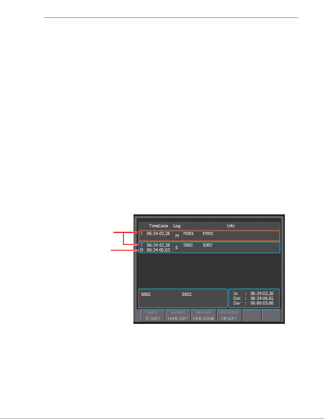
• White cursors indicate that the item is selected add itionally.
Timecode when the Add Mrk
button was pressed
Timecode when the Previous
button was pressed
• Green cursors indicate that the item is being replayed.
• Red cursors indicate that the item is being cued up.
• Dashed cursors indicate that the item is being cued up or played in another
playback channel.
About multiple selection of items
You can select multiple items to copy, move, or delete them.
About multiple selection of items
To select multiple items, touch them while holding down the
range of items, press the
holding down the
Shift button, and then press the first and last items while
Fn button.
About marking and scenes
If the Add Mrk button is pressed, an In point is marked on the record train. If you
perform the following operations, In and Out points are marked on the record train
allowing you to handle them as a scene.
• If you press the Add Mrk button during a live playback and cue up the video with
Previous button:
the
In this case, two items are added to the list: a marked item whose In point is set as
the point where t he
is set as the point where the
as the point where the
Add Mrk button was pressed, and a scene item whos e In point
Previous button was pressed.
Fn button. To select a
Add Mrk button was pressed while its Out point is set
15 April 2010 K2 Dyno Controller User Manual 89
Page 90
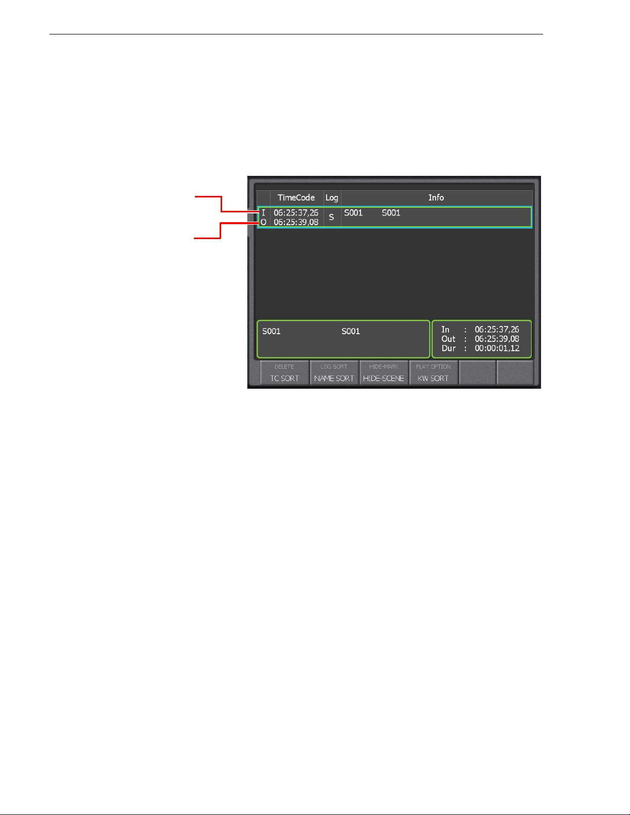
Chapter 5 Marking Function
Timecode when the T-Bar
operation was started
Timecode when the Out
button was pressed
• If you perform a reverse playback with the JOG knob and play the video with the
T-Bar:
In this case, the controller automatically enters the trim mode. The In point is set
as the point where you began t o operat e the T- Bar whil e the Out po int is set as t he
point where you stop the playback moving the T-Bar back to the 0% position.
However, the Out point is not fixed and it will be updated when you operate the
T-Bar again. To fix the Out point, press the
Out button.
NOTE: If you press the Live button after operat ing the JOG knob or T-Bar, the Out
point is set at the point where the button was pressed and the controller returns to
the live playback.
NOTE: A scene is not created even when you operate the JOG knob, T-Bar, or
ous/Next button during a l ive playback if
Previ
Auto Scene is set to OFF in "CLIP"
of the CONFIG screen or if the system is in the pseudo live mode. For more
information, see "About the pseudo live mode" on page 65 or "Clip settings" on
page 166.
• If you press the
In/Out button during a live playback:
In this case, the controller automatically enters the trim mode. A scene that has a
temporary Out point will be created, setting the point where the
pressed as the In point. After that, if you press the
Out button, the point where you
In button was
pressed the button will be fixed as the Out point.
NOTE: Pressing the
playback cues up to the point where the
Cue Up button after pressing the In or Out button during a live
In point was pressed.
• If you press the In/Out button while playing the record train:
In this case, the controller automatically enters the trim mode. A scene that has a
temporary Out point will be created, setting the playback timecode where the
In
button was pressed as the In point. After that, if you press the Out button at the
desired scene after you operate the JOG knob or replay the scene, the playback
timecode where you pressed the button will be fixed as the Out point.
90 K2 Dyno Controller User Manual 15 April 2010
Page 91

Cueing up to the previous or next item using the JOG knob (Browse mode)
NOTE: If you press the Out button without pressing the In button during a live
playback or while playing the record train, the timecode when the button was
pressed is set as the Out point, which automatically adds the In point with the
default duration. For more information on how to set the default duration, see
"Clip settings" on page 166.
NOTE: If you want to modify the In and Out points of a created scene, see
"Trimming" on page 96.
NOTE: Pressing the
the In/Out point with the playback timecode where the button was pressed.
NOTE: While playing a scene, the playback will not be stopped even after passing
e Out point until you perform an operation to change the playback status.
th
NOTE: In and Out points added on the record train as marks or scenes are not
ected. Therefore, these In and Out points will be deleted when a LoopRec
prot
operation is performed on the recor d train. Sav e important scenes in a h ighlight o r
library as clips or turn off the LoopRec setting. For more information on how to set
LoopRec, see "Changing the channel configuration for standard channels" on
page 25.
In/Out button, during a rep lay of a s cene you cued up, updates
Cueing up to the previous or next item using the JOG knob
(Browse mode)
In the Browse mode, you can use the JOG knob to quickly cue up to the previous or
next item.
1. Select an item.
• Select any item in the MARK, HIGHLIGHT, LIBRARY, PLAYLIST, or
SEARCH scre
NOTE: For operations in the expansion screen, the selection is invalid if the
ected item is not shown on the touch panel even if it is displayed in the expansion
sel
screen.
en. For the PLAYLIST screen, select an event.
2. Press the
• The controller enter s t h e Brows e mode and t he
During the Browse mode, the normal oper ations to rewind/fast forward with the
JOG knob are disabled.
3. Rotate the JOG knob to the right or left.
• The playback pointer moves to the previous or next items consecutively for
cuei
the playback pointer moves to the previous or next event for cueing up.
• To exit the Browse mode, press the
button.You can also pr ess the
live playback.
15 April 2010 K2 Dyno Controller User Manual 91
Shift button, and then press the Brws butt on.
Brws button lights up in green.
ng up from the one you sele cted in s tep 1. If y ou select ed an event in step 1,
Shift button, and then press the Brws
Live button to exit the Browse mode and ente r the
Page 92
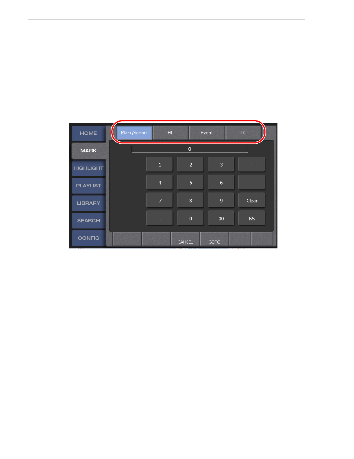
Chapter 5 Marking Function
Cueing up an item by specifying it with a number
You can cue up an item by entering its number or timecode.
1. Press the
• The Goto screen appears.
2. Select the target item.
• To enter the timecode, touc h
Goto button.
TC. You can touch up/down Previous/Next button
to specify a timecode from 365 days befor e to 365 days after in the same sessi on.
3. Enter the number or timecode, and then press
GOTO.
92 K2 Dyno Controller User Manual 15 April 2010
Page 93

Entering the logging information
Button operation
Adding marks during a live playba ck may result in a large number of marks. You can
enter information such as names, keywords, or ratings, so that important scenes can
be identified easily.
NOTE: Keywords and icons in lo gging information can be edit ed for import, e.g. on
ernal PC. For more information about editing and importing keywords, see
an ext
"Editing and storing keywords" on page 187.
Entering information with the touch panel
1. Display the MARK screen, and then touch a nd selec t the ma rk for which y ou want
to enter information.
Entering the logging information
Press the
information.
• When the HOME screen is displayed, pressing the
displays the MARK screen.
2. Touch the property panel.
Previous/Next button to select the mark for which you want to enter
Previous/Next button
15 April 2010 K2 Dyno Controller User Manual 93
Page 94

Chapter 5 Marking Function
3. Touch Name.
• If your K2 Dyno Controller is connected to a keyboard, a name can be entered
directly.
4. Select a name.
• You can switch the categories by touching
</> at the top of the touch panel. In
addition, you can move one level up in the directory by touching the category
name panel at the top of the touch panel.
• Category names a re displayed in orang e and each keyword is displayed in white.
To choose a category, double-touch the category.
• To enter a name that is not l isted in the pane l, t ouch
KEYBOARD at the bottom
of the panel and enter the de sired characters.
• If you turn on
Append, the selected keyword can be added to the end of the
entered string separating them with a space. Once you have finished entering a
name, touch
BACK.
5. Touch the "Keyword" panel.
6. Enter a keyword.
• You can switch the categories by touching
</> at the top of the touch panel. In
addition, you can move one level up in the directory by touching the category
name panel at the top of the touch panel.
• Category names a re displayed in orang e and each keyword is displayed in white.
To choose a category, double-touch the category.
• Up to three keywords can be entered in a row. If you want to enter only one or
two keywords, touch
BACK after ente ring them.
94 K2 Dyno Controller User Manual 15 April 2010
Page 95

Entering information with shortcuts
• To enter a keyword that is not listed in the panel, touch KEYBOARD at the
bottom of the panel and enter the desired characters.
7. From "Rating", touch and select the number of the rating.
8. Touch
9. Touch
•Touch
•Touch
•Touch
Icon, and then select an icon.
BACK to return.
CLEAR ALL to delete the entered logging information.
RESTORE to restore the logging information prior to editing.
DEFAULT to store the current logging inf ormation as default. If you store
the default logging information, the stored logging information will be set to a
mark when adding one. You can check and set the default logging information
in "NAME" of the CONFIG screen. For more informat ion, see "Default logging
settings" on page 183.
Entering information with shortcuts
You can enter lo gging information with shortcuts when a keyboard is connected to the
K2 Dyno Controller. You can enter information with the following shortcuts after
selecting the mark for which you want to enter logging information.
NOTE: Use number keys on the main keyboard when entering a number with
ortcuts. You cannot enter a number with a numerical keypad.
sh
• Press the [Ctrl] + [4] keys to enter a name .
• Press the [Ctr l] + [ 1]/[2 ]/ [3] ke ys to en ter t he ke yword 1, k eyword 2 or keyword 3.
• Press the [Ctrl] + [Space] keys to enter a rating. Press the [Ctrl] + [Space] keys one
time to enter one star, press the keys two times to enter two stars, press the keys
three times to enter three stars, and pre ss the keys four times to delete the entered
stars.
15 April 2010 K2 Dyno Controller User Manual 95
Page 96

Chapter 5 Marking Function
Button operation
Button operation
Trimming
You can modify the In/Out point of a scene.
NOTE: A marked item with only an In point cannot be trimmed.
1. Display the MARK screen, and then touch and select the scene you want to trim.
Press the
• When the HOME screen is displayed, pressing the
2. Touch the In/Out/Dur panel.
Press the Shift button, and then press the Trim button.
Previous/Next button to select the scene for which you want to trim.
displays the MARK screen.
Previous/Next button
96 K2 Dyno Controller User Manual 15 April 2010
• The controller enters the trim mode. In the trim mode, the
buttons light up in yellow.
• For the button operatio n, the controller cues up to the In point location of the
selected scene.
In, Out, and Trim
Page 97
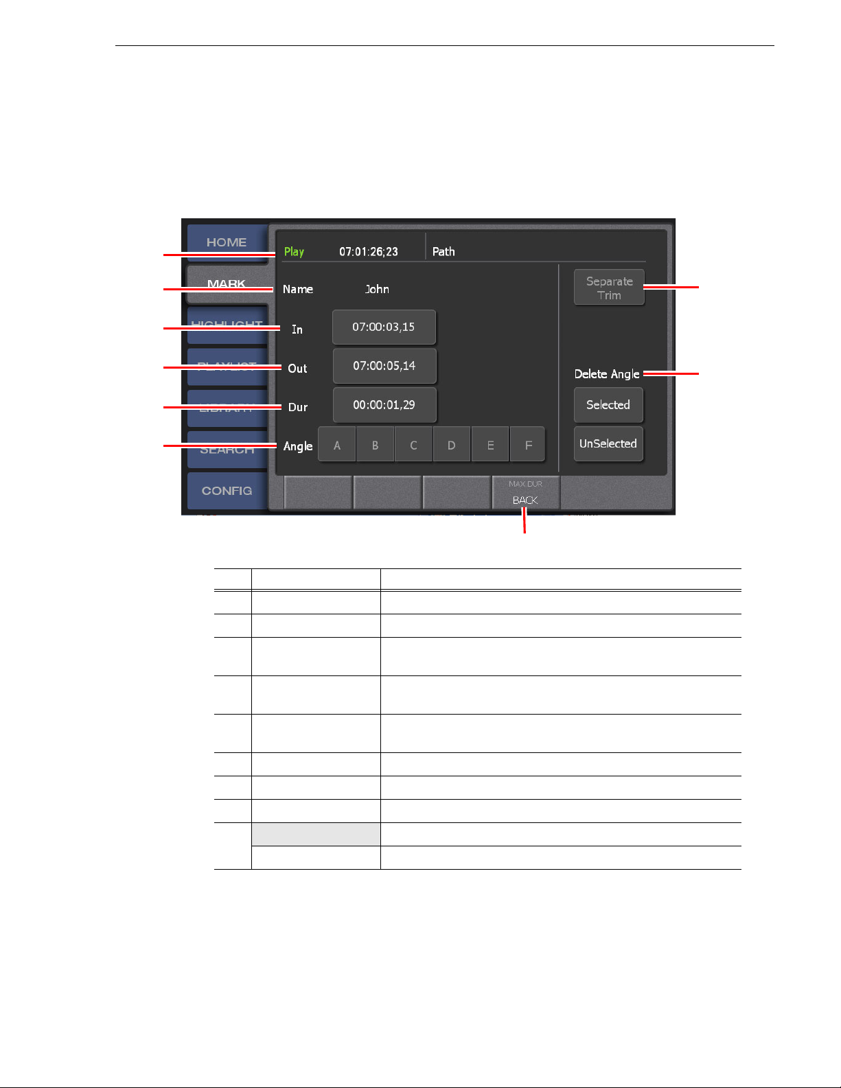
• The trim mode screen appears. For more information about the indication
(1)
(2)
(3)
(4)
(5)
(6)
(9)
(8)
(7)
meanings and individual panel functions, see the following table. To perform
functions (indicat ed by t he shaded area in the ta ble) tha t are di splayed a t the to p
of the menu panels shown at the bottom of the scr een, press the
Shift button, and
then touch the de sired menu panel. For more information on how t o use the
button, see "About Shift button operations" on page 21.
Trimming
Shift
No. Name Function
(1) Play
(2) Name
(3) In
(4) Out
(5) Dur
(6) Angle
(7) Separate Trim
(8) Delete Angle
(9) MAX DUR
BACK
Shows the timecode of t he playback pointer.
Shows the name of the item to be trimmed.
Shows the timecode of the In point. Touch the panel to edit the
timecode of the In point of a scene.
Shows the timecode of the Out point. Touch the panel to edit the
timecode of the Out point of a scene.
Shows the duration of the scene. Touch the panel to edit the duration
of a scene.
Not available.
Not available.
Not available.
Set the duration of the scene to "12 hours-2 frames".
Returns to the previous screen.
15 April 2010 K2 Dyno Controller User Manual 97
Page 98

Chapter 5 Marking Function
Button operation
3. Touch the panel you want to edit from the In, Out, or Du r panel, enter the timeco de,
and then touch
Either operate the JOG knob or play a scene, and press the In/Out button at the
desired scene while watching the monitor.
• Setting the In/Out point changes the duration automatically.
• Editing the duration automatically changes the timecode of the Out point.
ENTER.
• Pressing the
In/Out button sets the playback timecode, at the point when the
button is pressed, as the In/Out point.
• When you set the
In/Out point (when you press the In/Out button), the
respective button lights up in green.
• If you press the
Take button, the trim mode is finishe d to retu rn to the pr evi ous
screen.
98 K2 Dyno Controller User Manual 15 April 2010
Page 99

Chapter 6
Highlight
This chapter consists of the following :
• "Components in the HIGHLIGHT screen" on page 100
• "Storing and removing scenes in a highlight" on page 102
• "Match frame operations from highlights to the record train" on page 104
• "Trimming in a highlight" on page 105
• "Managing highlight bins" on page 108
• "Managing highlight bins" on page 108
• "Setting bookmarks in a highlight" on page 111
• "Transferring items (SEND function)" on page 113
15 April 2010 K2 Dyno Controller User Manual 99
Page 100

Chapter 6 Highlight
(5)
(1) (2) (3)
(7)
(4)
(6)
(8) (10)
(1)
(11)
(9)
Components in the HIGHLIGHT screen
Items stored in a hi ghlight are mana ged in a b in and re main sav ed unt il the se ss ion is
deleted. A bin provides boxes called shot boxes which allow you to save highlight
items by adding items to these boxes. The HIGHLIGHT screen displays the list of
highlights in the selected bin. By default, a highlight bin named "Bin1" is expanded.
1. Touch the
HIGHLIGHT tab.
• The HIGHLIGHT screen appears. For more information about the indication
meanin
gs and individual panel functions, see the following table. To perform
functions (indicat ed by t he shaded area in the t able) th at are di splayed at the t op
of the menu panels shown at the bottom of the screen, press the
Shift button, and
then touch the de sired menu panel. For more informatio n on how to use the
button, see "About Shift button operations" on page 21.
Shift
No. Name Function
(1) < / >
(2) Bin name /
Bin number
100 K2 Dyno Controller User Manual 15 April 2010
Touch this to move to another highlight bin.
Shows the number and name of the displayed highlight bin. Touch this
to move one level up in the directory and select a highlight bin to be
displayed.
 Loading...