

GRASS VALLEY IQDMX01, IQDMX03, IQDMX11, IQDMX13 User Manual

IQDMX01/03/11/13 B5
IQDMX01OPS 05/04/07 www.snellwilcox.com Version 1 Issue 12 B5.1
IQDMX01/03/11/13
4/8 Channel AES/EBU Demultiplexer
Table of Contents
Module Description ............................................. 2
Rear Panel Views ................................................. 2
Product Comparison ........................................... 4
Block Diagram...................................................... 6
Features................................................................ 6
Resolution of Audio Processing ........................ 7
Technical Profile .................................................. 8
INPUT CONNECTIONS ...................................... 10
Serial Digital Video Inputs ......................... 10
Reference .................................................. 11
OUTPUTS............................................................ 12
Serial Digital Video Outputs ...................... 12
GPI I/O (not available on -1A versions)..... 12
AES Outputs.............................................. 13
CARD EDGE INDICATORS ................................ 16
RollCall PC Control Panel Screens .................. 17
Video ......................................................... 17
ProcAmp.................................................... 18
De-embed Pair 1-4 and 5-8 ....................... 19
Audio Mix 1, 2, 3 and 4.............................. 20
Audio Bus A and B/Audio Bus C and D .... 21
Audio Embed ............................................. 22
AES Out..................................................... 23
Audio Delay Setup..................................... 24
Audio Setup ............................................... 25
Video Delay ............................................... 27
VBI & HANC Blank(ing) ............................. 28
Caption & Pattern ...................................... 29
GPI............................................................. 30
RollTrack ................................................... 32
Memories................................................... 34
Logging 1, 2, 3 and 4................................. 35
ROLLCALL LOG FIELDS .......................... 36
Setup ......................................................... 38
Operation from an Active Control Panel ......... 40
MAIN MENU .............................................. 44
Video.......................................................... 44
Freeze........................................................ 45
User Mem(ories)........................................ 46
Audio.......................................................... 47
Video Delay ............................................... 53
Setup…...................................................... 54
ROLLCALL LOG FIELDS .......................... 64
IQDMX01 RollCall Commands .......................... 67
RollTrack Audio Delay Tracking ...................... 75
Appendix 2 HANC & Embedding...................... 80
Manual Revision Record ................................... 81
C
IQDMX01/03/11/13 B5
IQDMX01OPS 05/04/07 www.snellwilcox.com Version 1 Issue 12 B5.2
Module Description
The IQDMX01 and IQDMX11 are 2/4 x AES/EBU
stream demultiplexers with advanced embedded
audio handling. All audio manipulation is at the
channel-level suiting discreet surround and multilingual use. In addition to its tracking audio delay, it
also has a bulk audio delay feature. To complete
the delay flexibility, it has a built-in video delay that
can be used to adjust to match external audio
processing delays, such as that from a Dolby E
encoder. Its audio firewall capability ensures
continuous audio output even when the embedded
audio signal fails. A dual SDI input allows this
module to take signals from either of two paths
thus allowing split operation, with video taken from
one input and embedded audio from the other.
The IQDMX01 and IQDMX11 can also be used as
embedded audio processors. Their ability to remultiplex the audio internally after channel
manipulation and processing means that they can
be used in this role with the AES outputs used for
monitoring feeds.
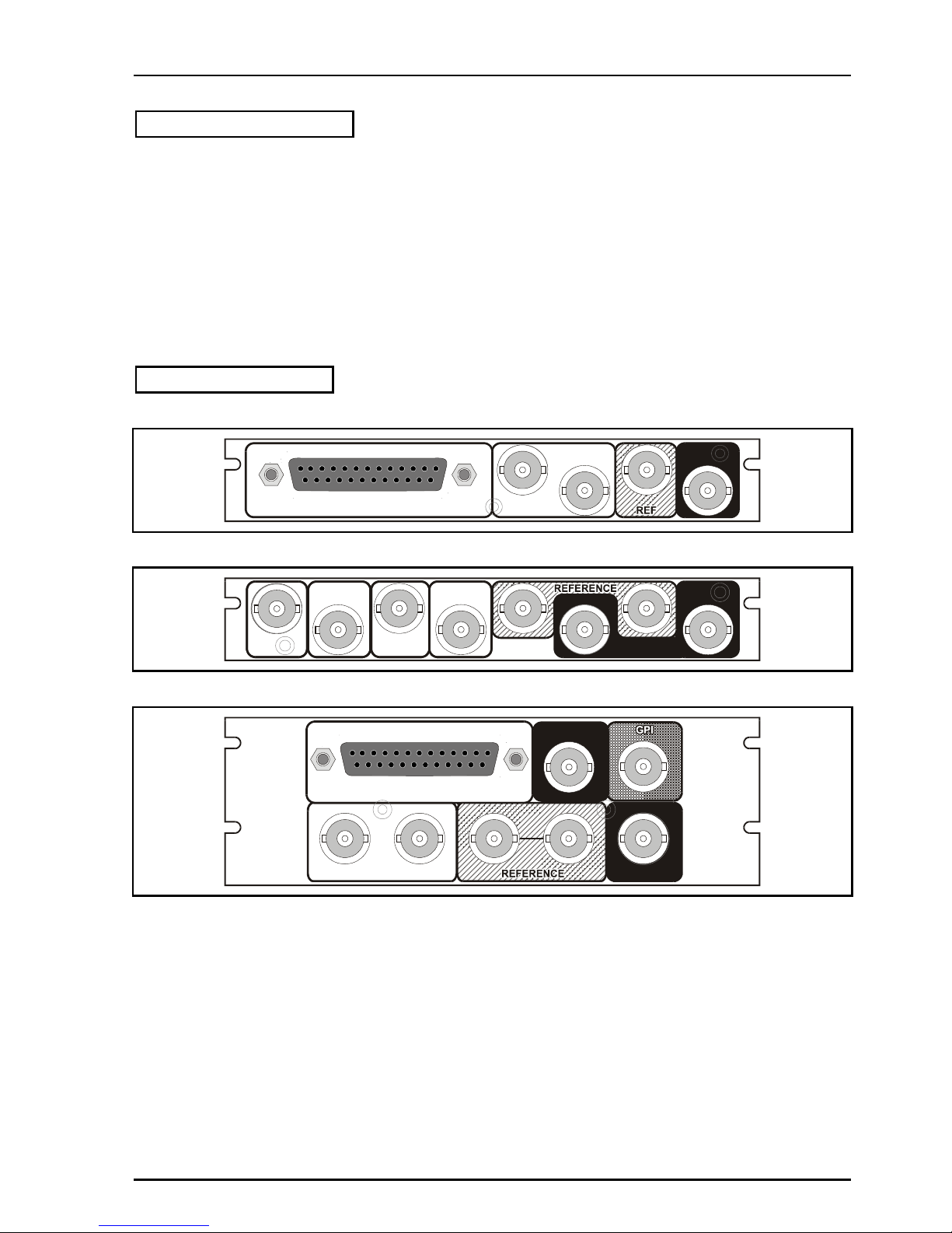
Rear Panel Views
IQDMX0315-1A
AES AUDIO OUT
SERIAL
OUT
1
2
SERIAL
IN
I
Q
D
M
X
0
/
1
_
1
5
1
A
IQDMX0101-1A
SER OUT
SERIAL
IN 2
SER OUT
IQDMX0
_01-1A
2 1
SERIAL
IN 1
AES OUT
1
AES OUT
2
iQDMX0217-2A, IQDMX0217-2A
SERIAL IN 2
AES AUDIO OUT
12
SERIAL IN 1
SERIAL OUT
I
Q
D
M
X
0
/
1
_
1
7
2
A
IQDMX01/03/11/13 B5
IQDMX01OPS 05/04/07 www.snellwilcox.com Version 1 Issue 12 B5.3
IQDMX0103-2A, IQDMX0006-2A
AES OUT
2
1
SERIAL IN 2
2
1
IQDMX0
_03-2A
SERIAL OUT
SERIAL IN 1
IQDMX0006-2A
SERIAL IN
2 1
AES OUT
1
3
4
2
SERIAL OUT
IQDMX1
_06-2A
2 1
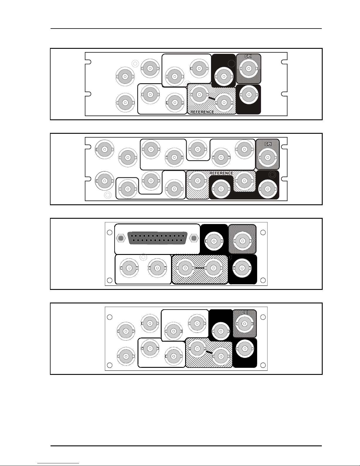
IQDMX0216-2, IQDMX0216-2
IQDMX0/1
_16-2
AES AUDIO OUT
12
SERIAL IN 1
SERIAL OUT REFERENCE
GPI
SERIAL IN 2
IQDMX0102-2
REFERENCE
IQDMX0
_02-2
GPI
AES OUT
2
1
2
1
SERIAL OUT
SERIAL IN 1
GPI
SERIAL IN 2
IQDMX01/03/11/13 B5
IQDMX01OPS 05/04/07 www.snellwilcox.com Version 1 Issue 12 B5.4
Versions of the module cards available are:
Order codes for IQH3A enclosures
IQDMX0101-1A SDI and 4 channel AES demultiplexer with extended video delay. Unbalanced AES
connection. 2 SDI inputs, 2 AES outputs, 2 SDI outputs
IQDMX0103-2A SDI and 4 channel AES demultiplexer with extended video delay. Unbalanced AES
connection. 2 SDI inputs, 2 AES outputs, 2 SDI outputs, 1 GPI
IQDMX0315-1A SDI and 4 channel AES demultiplexer with extended video delay. Balanced AES connection.
1 SDI input, 2 AES outputs, 2 SDI outputs
IQDMX1315-1A SDI and 8 channel AES demultiplexer with extended video delay. Balanced AES connection.
1 SDI input, 4 AES outputs, 2 SDI outputs
IQDMX1317-2A SDI and 8 channel AES demultiplexer with extended video delay. Balanced AES connection.
2 SDI inputs, 4 AES outputs, 2 SDI outputs, 1 GPI
IQDMX0317-2A SDI and 4 channel AES demultiplexer with extended video delay. Balanced AES connection.
2 SDI inputs, 2 AES outputs, 2 SDI outputs, 1 GPI
IQDMX1106-2A SDI and 8 channel AES demultiplexer with extended video delay. Unbalanced AES
connection. 2 SDI inputs, 4 AES outputs, 2 SDI outputs, 1 GPI
IQDMX0317-2A SDI and 4 channel AES demultiplexer with extended video delay. Balanced AES connection.
2 SDI inputs, 2 AES outputs, 2 SDI outputs, 1 GPI
Order codes for other enclosures
IQDMX0316-2 SDI and 4 channel AES demultiplexer with extended video delay. Balanced AES connection. 2
SDI inputs, 2 AES outputs, 2 SDI outputs, 1 GPI
IQDMX0102-2 SDI and 4 channel AES demultiplexer with extended video delay. Unbalanced AES connection.
2 SDI inputs, 2 AES outputs, 2 SDI outputs, 1 GPI
IQDMX1316-2 SDI and 8 channel AES demultiplexer with extended video delay. Balanced AES connection. 2
SDI inputs, 4 AES outputs, 2 SDI outputs, 1 GPI
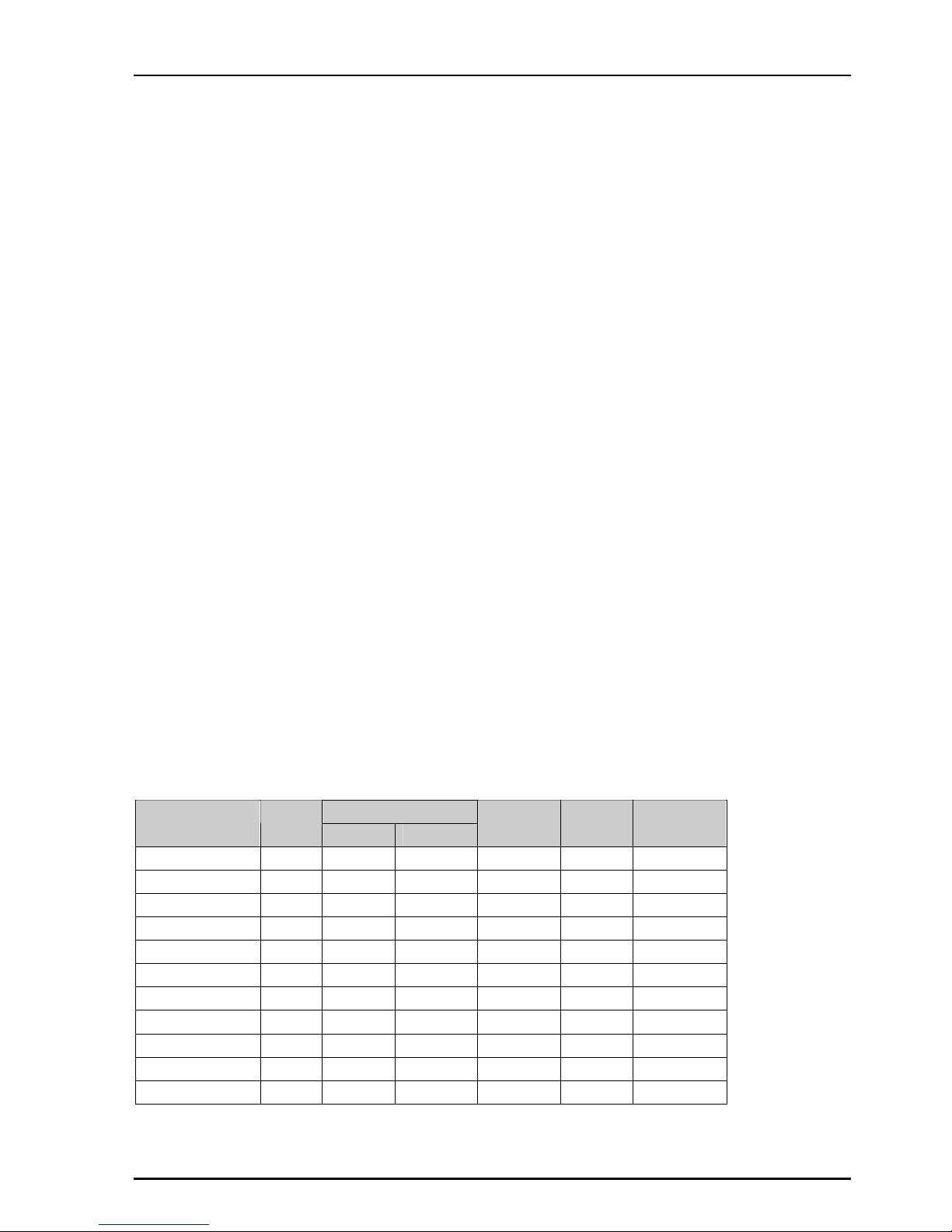
Product Comparison
AES Outputs
Product
SDI
Inputs
Number Type
SDI
Outputs
GPI
Width &
Style
IQDMX0101-1A 2 2 U/B 2 Single A
IQDMX0315-1A 1 2 BAL 2 Single A
IQDMX1315-1A 1 4 BAL 2 Single A
IQDMX0103-2A 2 2 U/B 2 1 Double A
IQDMX1106-2A 2 4 U/B 2 1 Double A
IQDMX0317-2A 2 2 BAL 2 1 Double A
IQDMX1317-2A 2 4 BAL 2 1 Double A
IQDMX0317-2A 2 2 BAL 2 1 Double A
IQDMX0102-2 2 2 U/B 2 1 Double O
IQDMX0316-2 2 2 BAL 2 1 Double O
IQDMX1316-2 2 4 BAL 2 1 Double O
IQDMX01/03/11/13 B5
IQDMX01OPS 05/04/07 www.snellwilcox.com Version 1 Issue 12 B5.5
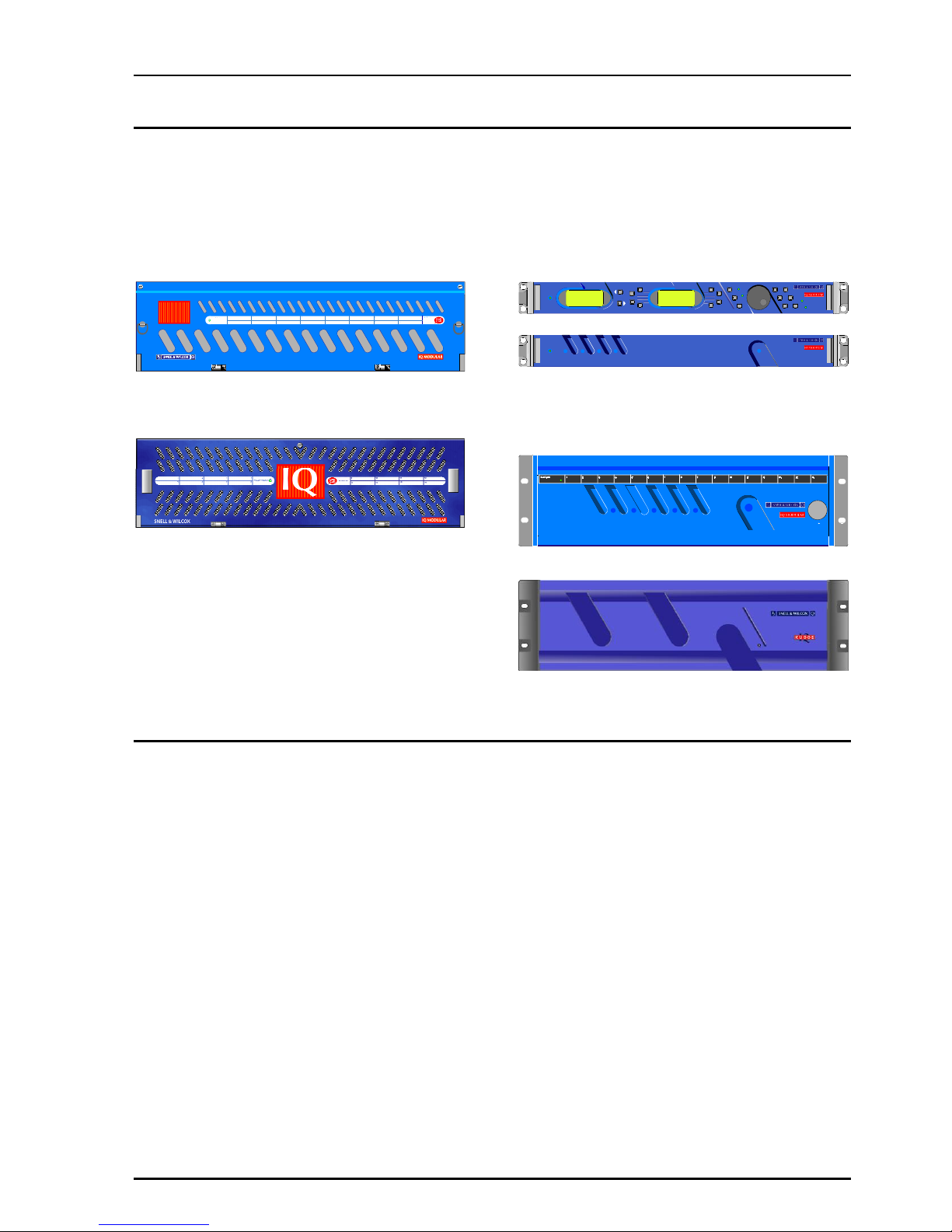
Note that there are two styles of rear panels available. They are not interchangeable between the two
styles of enclosures. However, the cards may be fitted into any style of enclosure.
‘A’ Style Enclosure
Rear panels with the suffix A may only be fitted
into the ‘A’ style enclosure shown below.
IQ
(Enclosure order codes IQH3A-E-0, IQH3A-E-P,
IQH3A-0-0, IQH3A-0-P)
(Enclosure order codes IQH3A-S-0, IQH3A-S-P)
‘O’ Style Enclosures
Rear panels without the suffix A may only be fitted
into the ‘0’ style enclosures shown below.
setup
lock save
recall
modules help
adjust
scroll
power
previous
return
home
control
information
display
select
power
(Enclosure order codes IQH1S-RC-0, IQH1S-RCAP, IQH1U-RC-0, IQH1U-RC-AP, Kudos Plus
Products)
power
OPEN
(Enclosure order codes IQH3N-0, IQH3N-P)
(Enclosure order codes IQH3U-RC-0, IQH3U-RC-P)
IQDMX01/03/11/13 B5
IQDMX01OPS 05/04/07 www.snellwilcox.com Version 1 Issue 12 B5.6
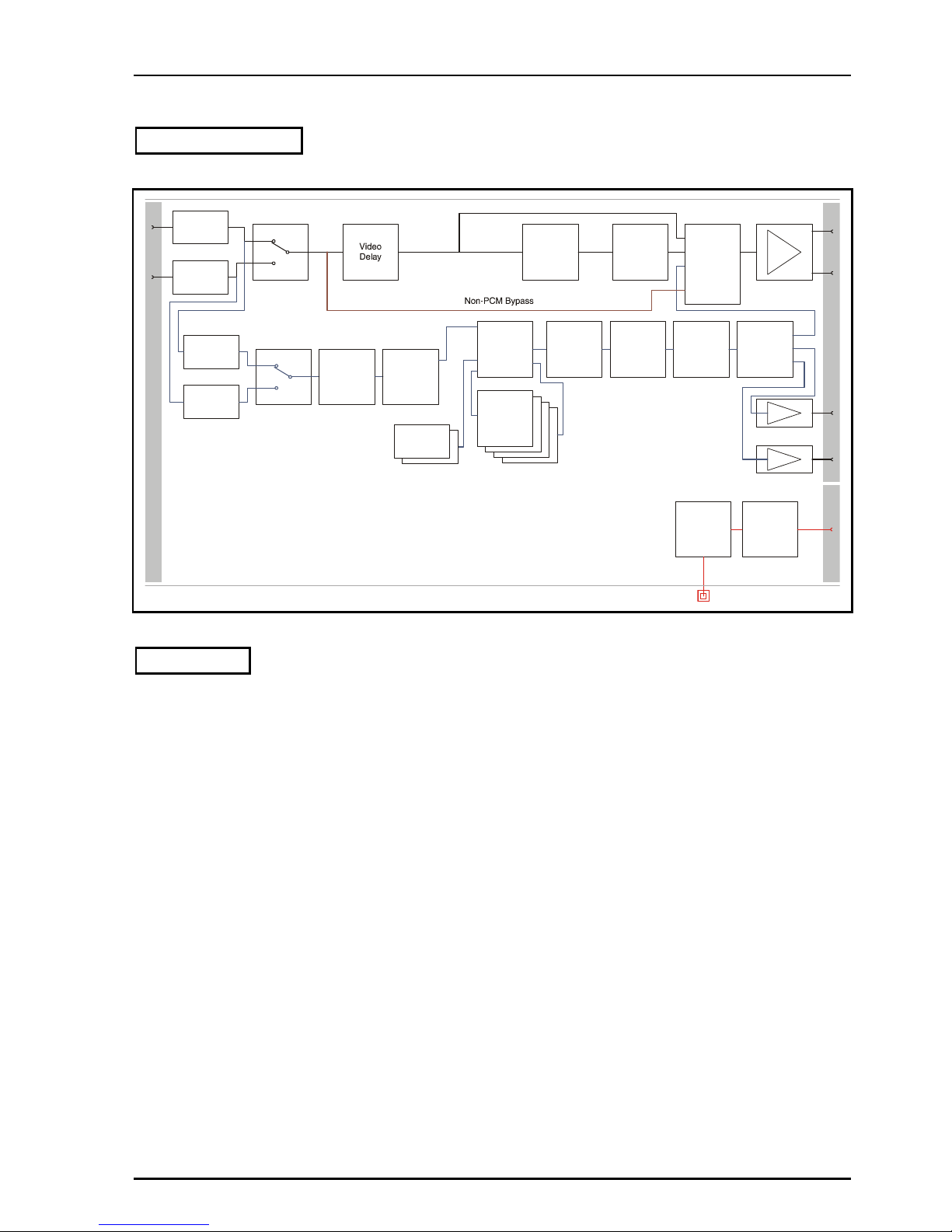
Block Diagram
O
u
t
p
u
t
s
Inputs
SDI RX &
Equalisation
Video
Proc. Amp
SDI TX
Selective
Ancillary
Blanking
SDI RX &
Equalisation
I
/
O
GPI Control
and
TTL Pulse I/O
Built-in
Intelligence
Ancillary data bypass
Network control monitoring
intelligence, and
Demux
Demux
Channel
Router
Audio
Tracking
Delay
Assignable
Audio
Mixers
Assignable
Audio
Mixers
Assignable
Audio
Mixers
Assignable
Audio
Mixers
Audio
Firewall
Tone
Generator
Tone
Generator
Additional
Delay
Signal
Monitoring
1 X GPI
1
2
1
2
AES TX
AES TX
1
2
Ancillary
Data
Multiplexer
Channel
Proc. Amp
Channel
Proc. Amp
Features
•
4/8 channel AES/EBU demultiplexer
•
Can de-embed AES/EBU and AC3 digital
audio data
•
Handles up to 24 bit embedded audio present
on the incoming SDI stream, and deembeds/embeds to 20 bits
•
Flexible audio delay including common fixed
delay and tracking delay
•
A further audio delay of up to 0.5s which
seamlessly tracks the video delay or external
RollTrack / GPI inputs
•
Firewall for processed PCM audio to provide a
continuous output
•
Transparent to non-PCM audio
•
Eight channel audio processor with channel
level manipulation
•
Channel level (Sub-frame) routing
•
4 off 4 channel audio mixers
•
Video proc-amp (gain, saturation, black level)
•
Video test pattern generator, 2 channel audio
tone generator
•
Up to 3 frames of video delay
•
RollCall control and monitoring compatible
IQDMX01/03/11/13 B5
IQDMX01OPS 05/04/07 www.snellwilcox.com Version 1 Issue 12 B5.7
Resolution of Audio Processing
Output Audio Format
Input Audio Format
AES SDI embedded
SDI embedded
Pass-through
SDI embedded non-PCM 20 20-bit 20-bit 20-bit
SDI embedded non-PCM 24 Not supported (1) Not supported (1)
24-bit
SDI embedded PCM 20 20-bit 20-bit 20-bit
SDI embedded PCM 24 20-bit (2) 20-bit (2) 24-bit
Notes:
1. Processing input formats that are not supported may produce corrupted output signals.
2. For some signals the output resolution may be less than the input resolution.

IQDMX01/03/11/13 B5
IQDMX01OPS 05/04/07 www.snellwilcox.com Version 1 Issue 12 B5.8
Technical Profile
Signal Inputs
Digital Video .......................2 x SDI (BNC) (1 x SDI – single
width versions)
Standards...........................SMPTE 259M-C-1997, SMPTE
272M-A-1994
Signal Outputs
Digital Video .......................SDI x 2
Unbalanced digital audio.....2/4 x AES/EBU, AC3, Dolby E
(BNC)
Balanced digital audio ....... 2/4 x AES/EBU, AC3, Dolby E (25
Way D-Type)
Standards .......................... SMPTE 259M-C-1997, SMPTE
272M-A-1994, AES3-1992
Control Interface
GPI .................................... 1x Closing contact I/O interface
(BNC)
Card Edge Controls
NONE
Card Edge Indicators
SDI Input Loss....................Loss = Off, Good = Green
SDI Input Error.................... Yellow = Unused input not at
current operating standard
CPU running / Power..........One green LED, flashing = OK
RollCall Functions
Audio Controls
Audio extraction select........SDI input 1/2/Follow Video Control
Set headroom.....................4 to 24 dB in 1 dB steps
Set audio detector thresholds
High and low levels, time delay
Input side control proc. - audio gain and polarity
Independent Gain, Mute, Polarity
control over de-embedded audio.
+18 dB to –18 dB in 0.1 dB steps.
Channel routing .................Output channels routed from test
tone, silence or SDI 8 embedded
channels from any group
Output side control proc. - gain and polarity
Independent Gain, Mute, & Polarity
control over embedded and AES
output channels. +18 dB to –18 dB
in 0.1 dB steps.
Global delay offset..............up to +1.5 s in 1 ms steps, common
to all processed audio.
Variable audio delay control source
Up to 0.5 s from RollTrack + GPI
Tone frequency, amplitude & Ident
2-channel tone generator. 100 Hz
to 15 kHz in 100 Hz steps.
Tone Setup:
Frequency .......................... 100 Hz to 15 kHz in 100 Hz steps
Channel Ident .....................0.5 s interruption every 2 s
Video Controls
Select primary input............1/2
Black Level.........................± 100 mV in 0.8 mV steps
Y/C Timing ........................ ± 592 ns in 148 ns steps
Picture position ................. ± 592 ns in 148 ns steps
Luminance Gain................. ± 6 dB
Chrominance Gain............. ± 6 dB
Video Horizontal Delay ...... +1 Line in 37 ns steps
Video Vertical Delay........... +1 Frame in 1 line steps
Video Delay Frames .......... 0 to +2 frames
Other Controls
Pass vertical data .............. On/Off (lines selectable 7/11 to
23/21 & 320/274 to 335/283)
Preset Unit......................... Returns all settings to default
Pattern Select .................... 100%/75% Bars, Multiburst, Black,
Animated Bars
User Memories .................. Name, clear, save and read 8 user
memories
Default Video Output.......... Pattern / freeze/ run through
Default Audio Output.......... Silence
Caption Output .................. On/Off (default and pattern output
only)
Caption Generator ............. Programmable up to 19 characters
GPI/O set-up...................... May be attached to any memory
function/polarity
Reporting (* also Logged)
EDH (for selected input)..... *Presence, *Error-Time, *Error-
Seconds
No SDI .............................. *No input present
Input ancillary error............ ANC error, ANC error-seconds
Input error.......................... Unused input not at current
operating standard
Report Embedded Audio Data
Report audio data pairs on input
and output SDI
Audio Silence, High Level, Low Level, Overflow
For processed audio channels only
RollTrack Input
Delay ................................. Audio delay – Fixed, RollTrack +
fixed

IQDMX01/03/11/13 B5
IQDMX01OPS 05/04/07 www.snellwilcox.com Version 1 Issue 12 B5.9
RollTrack Output
Delay..................................Current video/audio delay
Input state...........................Selected Input: Input Present, Input
Missing, Standard 525, Standard
625
Input 1: Input Present, Input
Missing, Standard 525, Standard
625
Input 2: Input Present, Input
Missing, Standard 525, Standard
625
GPI 1 Low, High, Inactive
Embedded Audio state .......De-embed 1-8 Lost/Present
Specifications
Video Internal Processing... 4:2:2 with 10 bit data paths
Serial Input Return Loss .....Better than 15 dB to 270 MHz
Maximum Input Cable length
> 200 m (PSF1/2 or equiv. cable)
Serial Output Level .............800 mV ±5%
Output Overshoot ...............< 70 mV
Output Return Loss.............Better than 15 dB to 270 MHz
Output Jitter........................< 0.2 UI (with 10 Hz High pass filter
selected on 601 monitor)
Minimum Delay ..................6 µs
Delay (Delay Mode)............6 µs - 3 Frames + 5.5 µs
THD+N ...............................< -117 dB @ 700 Hz (24 bits) AES
to AES
Digital Audio Output (Balanced)
Connector/Format............... 25 W D
Level...................................3 V p-p typical into 110 Ohms
Digital Audio Output (Unbalanced)
Connector/Format............... BNC
Level...................................1 V p-p typical into 75 Ohms
Power Consumption
Module Power Consumption
7.5 W max
IQDMX01/03/11/13 B5
IQDMX01OPS 05/04/07 www.snellwilcox.com Version 1 Issue 12 B5.10
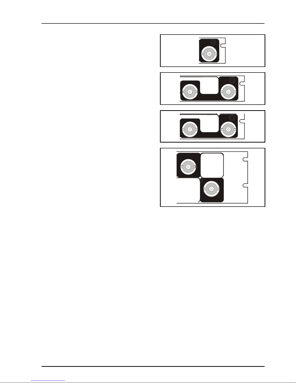
INPUT CONNECTIONS
Serial Digital Video Inputs
Serial digital inputs are made to the unit via BNC
connectors which terminate in 75 Ohms.
SERIAL
IN
SERIAL
IN 2
SERIAL
IN 1
SERIAL IN
2 1
SERIAL IN 2
SERIAL IN 1
IQDMX01/03/11/13 B5
IQDMX01OPS 05/04/07 www.snellwilcox.com Version 1 Issue 12 B5.11
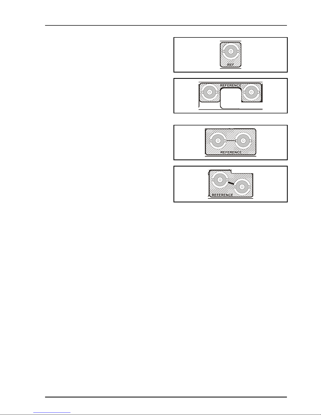
Reference
These connectors have no function on these
modules.
SERIAL
IN 2
SERIAL
IN 1
IQDMX01/03/11/13 B5
IQDMX01OPS 05/04/07 www.snellwilcox.com Version 1 Issue 12 B5.12
OUTPUTS
Serial Digital Video Outputs
These are the Serial Digital outputs of the unit via
BNC connectors for 75 Ohms.
GPI I/O (not available on -1A versions)
This connector is used for accepting GPI
information (from mechanical switch contacts,
relay contacts etc.) The resulting action that the
unit takes may be programmed via RollCall.
It may also be configured as an output.
SERIAL
OUT
1
2
SER OUT
SER OUT
2 1
AES OUT
1
12
SERIAL OUT
2
1
SERIAL OUT
SERIAL OUT
2 1
IQDMX01/03/11/13 B5
IQDMX01OPS 05/04/07 www.snellwilcox.com Version 1 Issue 12 B5.13
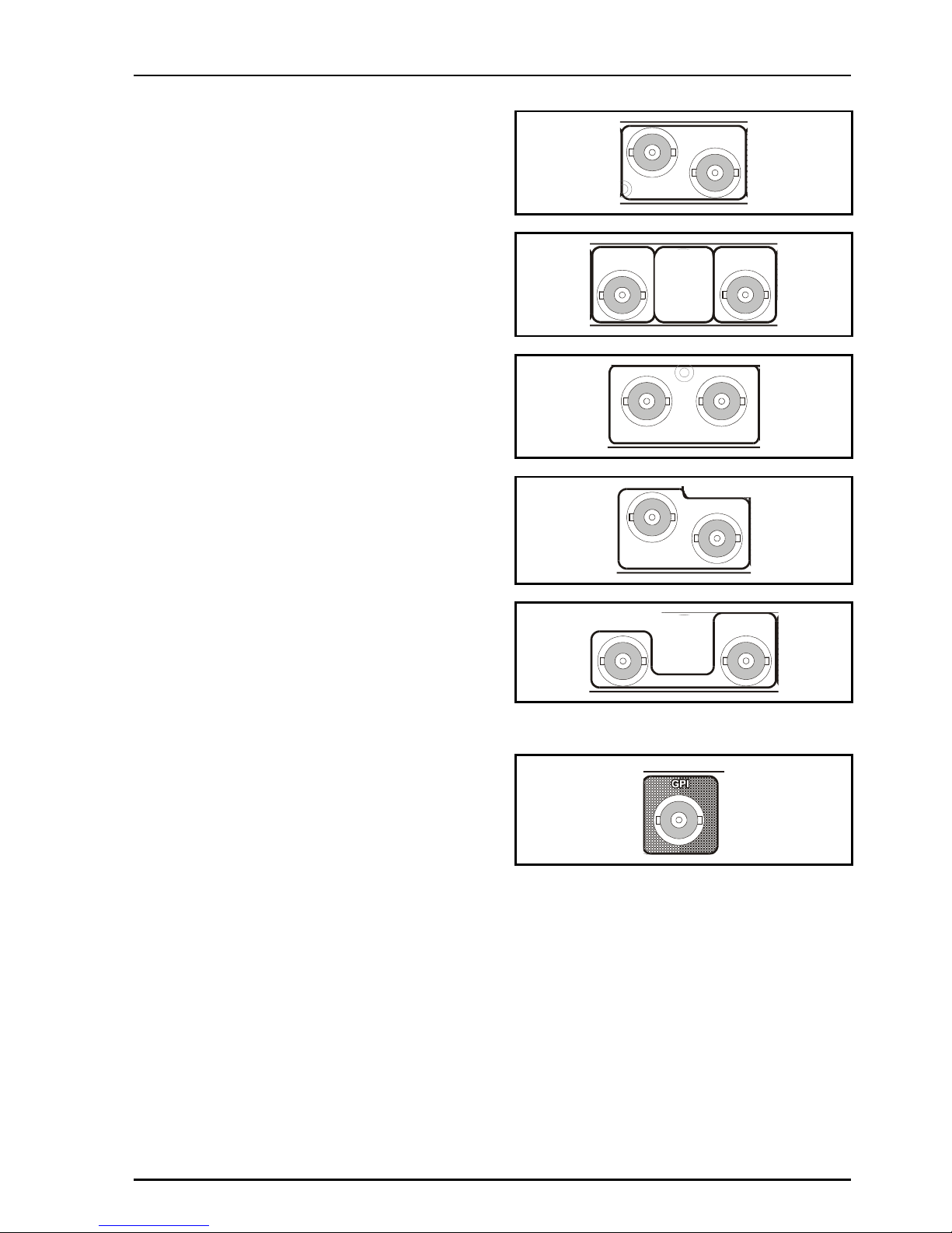
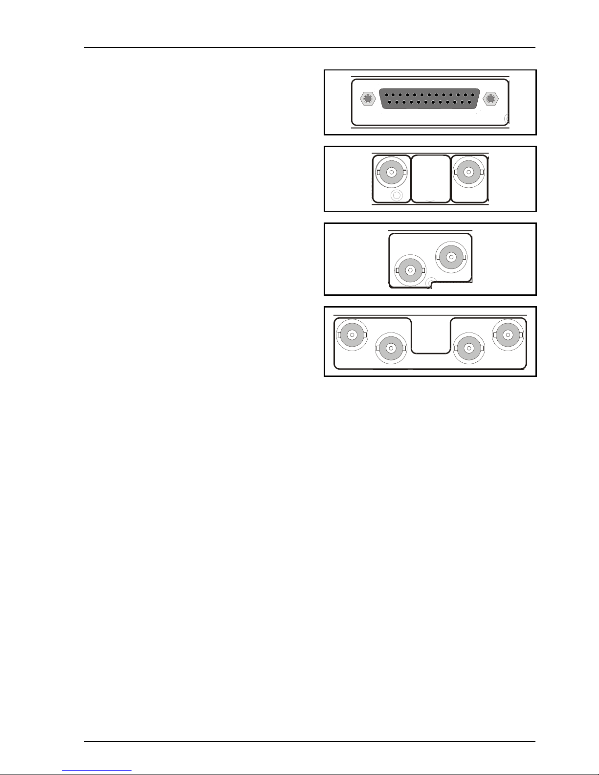
AES Outputs
All balanced AES outputs are available via a 25
way D type connector.
All unbalanced AES outputs are available via BNC
connectors for 75 Ohms.
AES AUDIO OUT
SER OUT
2
AES OUT
1
AES OUT
2
AES OUT
2
1
AES OUT
1
3
4
2

IQDMX01/03/11/13 B5
IQDMX01OPS 05/04/07 www.snellwilcox.com Version 1 Issue 12 B5.14
25 Way D Type Connection Details
25 Way D Connector
Pin Number
AES Outputs Standard Pin Assignment
1 CHASSIS
14 GND1
2 1+
15 1-
3 2+
16 2-
4 GND2
17 GND3
5 3+
18 3-
6 4+
19 4-
7 GND4
20 AES OUT 4 Ground GND5
8 AES OUT 4 + 5+
21 AES OUT 4 - 5-
9 AES OUT 3 + 6+
22 AES OUT 3 - 6-
10 AES OUT 3 Ground GND6
23 AES OUT 2 Ground GND7
11 AES OUT 2 + 7+
24 AES OUT 2 - 7-
12 AES OUT 1 + 8+
25 AES OUT 1 - 813 AES OUT 1 Ground GND8
IQDMX01/03/11/13 B5
IQDMX01OPS 05/04/07 www.snellwilcox.com Version 1 Issue 12 B5.15
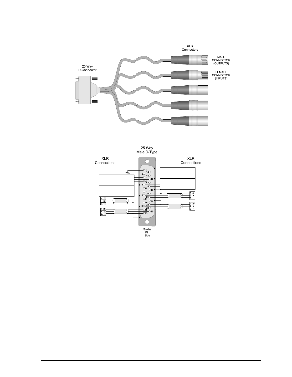
Example of Connection Details to XLR Connectors
AES Out 3
AES out 1
AES Out 4
AES Out 2
Do Not Use
Do Not Use
Do Not Use
Do Not Use
IQDMX01/03/11/13 B5
IQDMX01OPS 05/04/07 www.snellwilcox.com Version 1 Issue 12 B5.16
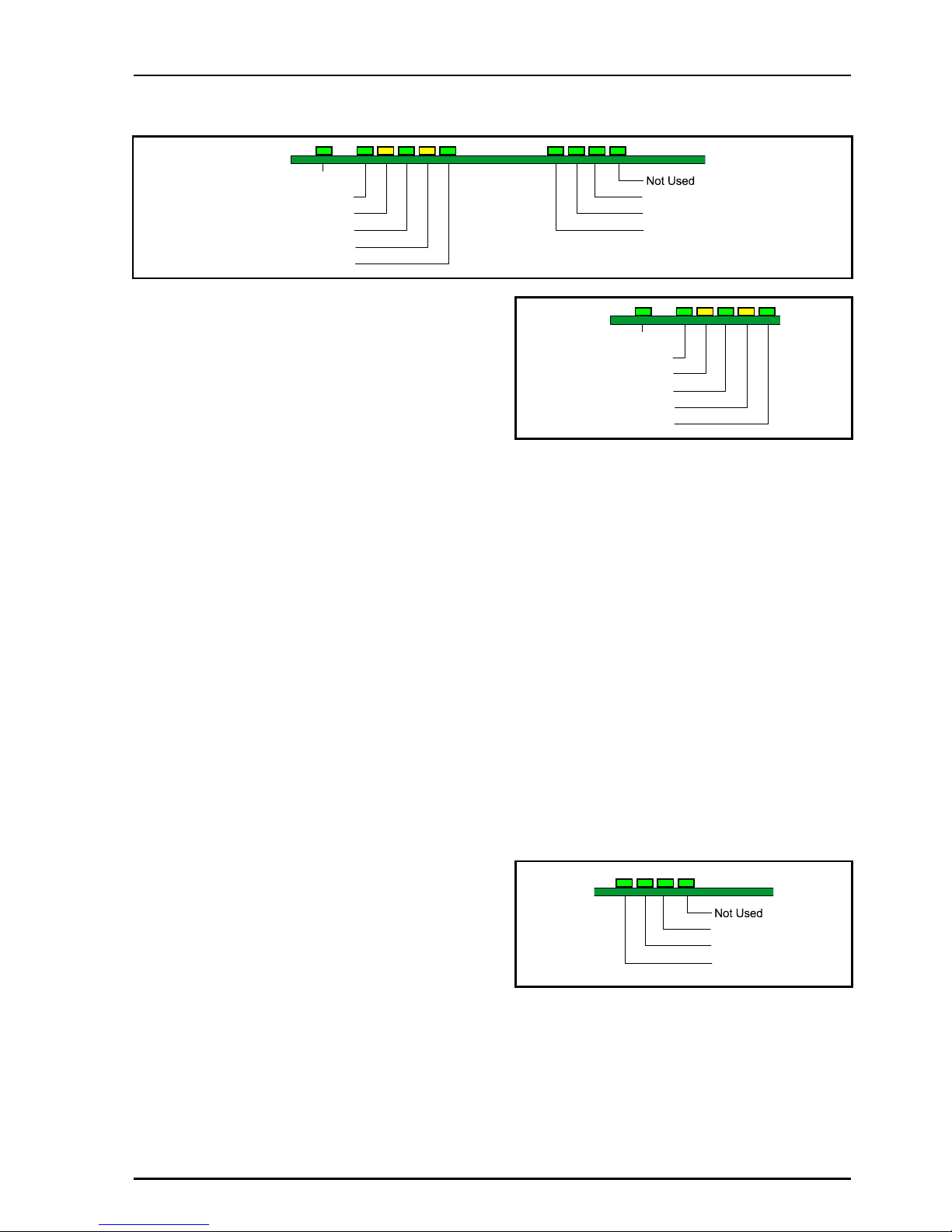
CARD EDGE INDICATORS
SDI 1 Present
CPU Run
SDI 1 Error
SDI 2 Present
SDI 2 Error
Ref Present
Not Used
Not Used
Not Used
Note that only the LED's associated with the
particular version of the product will be active.
CPU Run (Green)
This LED will flash to indicate that the CPU is
running.
SDI 1 Present (Green)
When illuminated this indicates that there is a valid
signal at SDI 1 input.
SDI 1 Error (Yellow)
When illuminated this indicates that SDI 1 input is
not at the current operating standard.
SDI 2 Present (Green)
When illuminated this indicates that there is a valid
signal at SDI 2 input.
SDI 2 Error (Yellow)
When illuminated this indicates that SDI 2 input is
not at the current operating standard.
Ref Present (Green)
This has no function on this unit.
Green x 4
These LED's have no function on this unit.
SDI 1 Present
CPU Run
SDI 1 Error
SDI 2 Present
SDI 2 Error
Ref Present
Not Used
Not Used
Not Used
IQDMX01/03/11/13 B5
IQDMX01OPS 05/04/07 www.snellwilcox.com Version 1 Issue 12 B5.17
RollCall PC Control Panel Screens
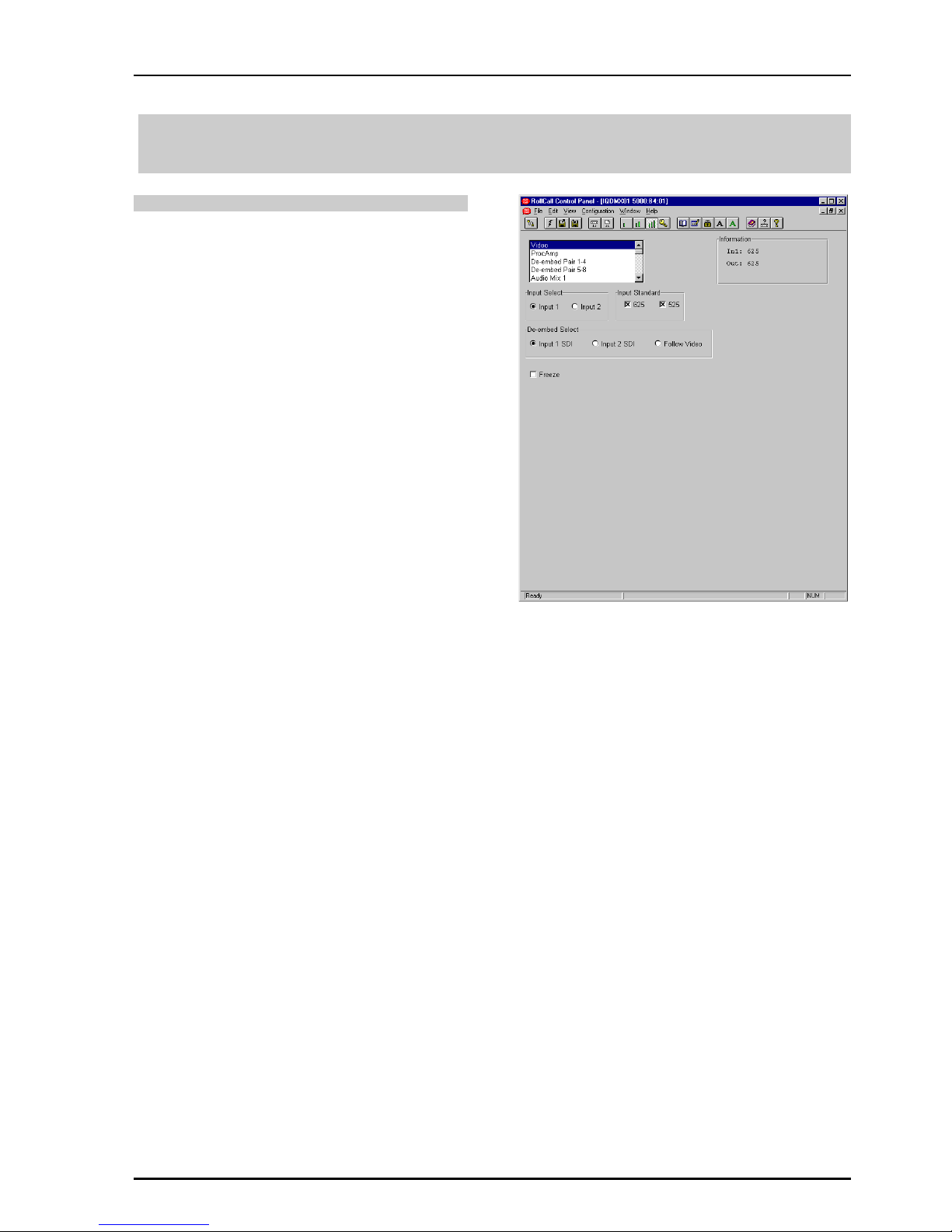
Video
Input Select
This allows either Input 1 or Input 2 to be selected
for processing.
Note that as the IQMUX0315-1A and
IQDMUX1315-1A versions have only one input,
Input 1 should always be selected. If Input 2 is
selected the unit will report an input loss.
Input Standard
This allows input standard to be selected.
If only 625 is selected the unit will be forced to only
accept 625 line inputs.
If only 525 is selected the unit will be forced to only
accept 525 line inputs.
If 625 and 525 are selected the unit will accept
both 625 and 525 line inputs.
DeEmbed Select
Either Input 1 SDI or Input 2 SDI may be selected
for DeEmbedding. If Follow Video is checked the
signal selected via the Input Select item will be
DeEmbedded.
Non-PCM groups can be transparently passed but
if a non-PCM group is selected for mixing or
routing it will be automatically muted.
If a Dolby header is detected in the data stream it
will be processed as a non-PCM signal.
Freeze
When checked the output picture will become a
frozen frame.
IQDMX01/03/11/13 B5
IQDMX01OPS 05/04/07 www.snellwilcox.com Version 1 Issue 12 B5.18
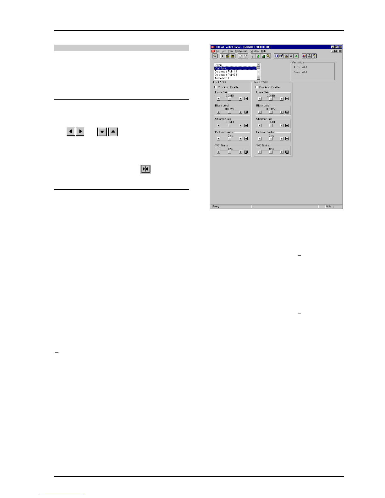
ProcAmp
These items allow signal levels and timings to be
adjusted.
Separate adjustments may be made for the two
input channels Input 1 SDI and Input 2 SDI.
Note that for this and other screens the following
applies to the scroll bars:
The and symbols at the ends of the
scroll bar allow the value to be adjusted in discrete
steps.
The numerical value will be shown next to the
scroll bars and selecting Preset will return the
setting to the calibrated value for that item.
Input 1 SDI and Input 2 SDI Controls
These items allow the gain, black level and timing
of both signals to be adjusted.
ProcAmp Enable
When checked the ProcAmp will become enabled
for that channel and the settings will be applied to
the signal.
When unchecked the settings will revert to the
preset values.
Luma Gain
This allows the Y (luminance) gain to be adjusted
by ±6 dB in steps of 0.1 dB. Preset value is 0.0 dB.
Black Level
This allows the black level to be adjusted by
+100mV in 0.8mV steps. Preset value is 0.
C Gain
This allows the Cb/Cr (color difference) gain to be
adjusted by ±6 dB in steps of 0.1 dB. Preset value
is 0.0 dB.
Picture Position
This item allows the timing of the picture position
relative to the normal value, to be adjusted.
The timing may be adjusted by +592ns in 148ns
steps.
Y/C Timing
This item allows the timing of the chrominance
signal relative to the luminance signal to be
adjusted, (i.e. Y to Cb/Cr timing) in nanoseconds.
The timing may be adjusted by +592ns in 148ns
steps.

IQDMX01/03/11/13 B5
IQDMX01OPS 05/04/07 www.snellwilcox.com Version 1 Issue 12 B5.19
De-embed Pair 1-4 and 5-8
This allows control of Gain, Mute, and Polarity over
the de-embedded channel pairs.
L and R
These scrollbars allow the gain of the Left and
Right channels to be adjusted over a range of
±18 dB in 0.1dB steps. Preset is to 0 dB.
Invert
When checked the signal polarity will be inverted.
Mute
When checked the signal will be muted.
Stereo
When checked the left and right channels will be
configured as a stereo pair and any adjustments
made to one channel will automatically be applied
to both channels.

IQDMX01/03/11/13 B5
IQDMX01OPS 05/04/07 www.snellwilcox.com Version 1 Issue 12 B5.20
Audio Mix 1, 2, 3 and 4
There are four separate audio mixers Mix 1, 2, 3
and 4.
Each mixer has four inputs with individual gain
controls that allow the mixing levels for each of the
input signals, to be adjusted. The range of
adjustment is from 0 to –90 dB and to Off.
0 to -60 dB is in steps of 1 dB, -60 dB to -90 dB is
in steps of 3 dB.
The inputs can be selected from the list in the
Source 1, 2, 3 and 4 items.
The outputs of these mixers provide four extra
input selections for the Channel Router.
IQDMX01/03/11/13 B5
IQDMX01OPS 05/04/07 www.snellwilcox.com Version 1 Issue 12 B5.21
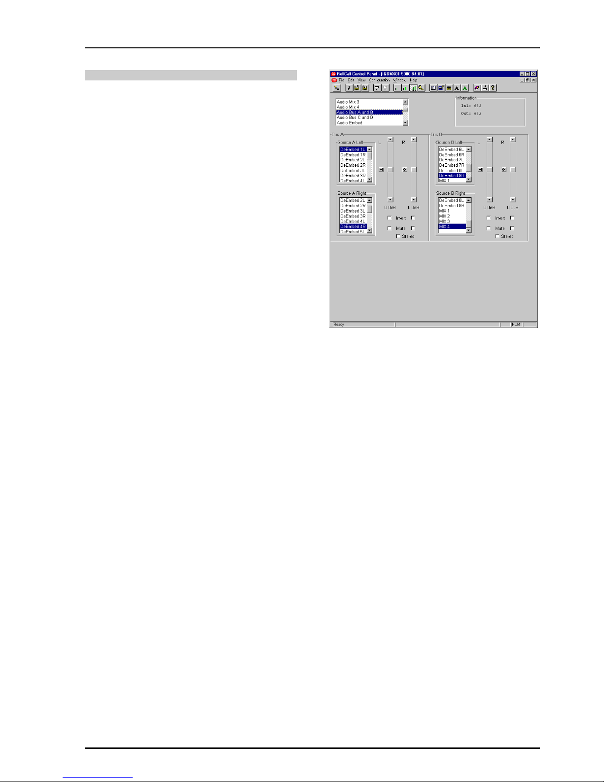
Audio Bus A and B/Audio Bus C and D
This function allows the inputs for the four audio
buses of the router to be selected.
For each bus any source may be selected from the
list for the left and right channels.
L and R
These scrollbars allow the gain to be adjusted over
a range of ±18 dB in 0.1dB steps. Preset is to
0 dB.
Invert
When checked the signal polarity will be inverted.
Mute
When checked the signal will be muted.
Stereo
When checked the left and right channels will be
configured as a stereo pair and any adjustments
made to one channel will automatically be applied
to both channels.
IQDMX01/03/11/13 B5
IQDMX01OPS 05/04/07 www.snellwilcox.com Version 1 Issue 12 B5.22
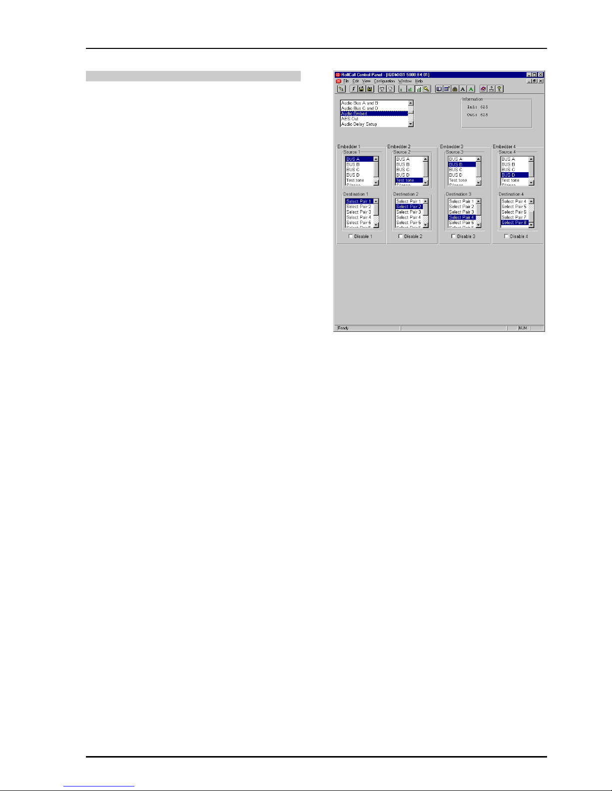
Audio Embed
This function sets up the embedder sources and
destinations. Higher number embedders have
priority, so if the same destination pair is selected
on two embedders, the highest embedder will be
the one that is active.
Embedder 1, 2, 3, and 4
The source of the signal for the embedder may be
selected from the list.
Destination 1, 2, 3, and 4
The destination for the embedded signal may be
selected from the list.
Disable 1, 2, 3 and 4
When checked the embedding will be turned off.
Non-PCM Signals
Note that for non-PCM signals sources both
embedders in the group (Group 1 = Embedder 1 &
2, Group 2 = Embedder 3 & 4) should be disabled.
For details of the Audio Embedding Packet
Distribution please refer to Appendix 2 on page 80.

IQDMX01/03/11/13 B5
IQDMX01OPS 05/04/07 www.snellwilcox.com Version 1 Issue 12 B5.23
AES Out
This allows the signal source for the AES output to
be selected from the list of items for the two AES
sources. Silence and audio test tones may also be
selected.
Passing Through Embeded non-PCM Signals
To pass embedded non-PCM signals direct to the
AES output DeEmbed (1 to 8) should be selected
from the Source list.
Note that in this mode all processing will be
bypassed.
IQDMX01/03/11/13 B5
IQDMX01OPS 05/04/07 www.snellwilcox.com Version 1 Issue 12 B5.24
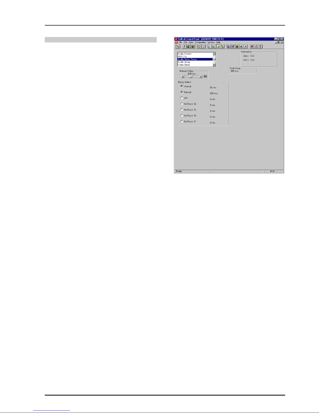
Audio Delay Setup
This screen allows the amount of delay to be set
and type of audio delay mechanism to be selected.
Manual Delay
This will affect all processed audio signals equally.
The delay may be set to up to +1.5 s in 1ms steps.
Delay Select
This allows the type of audio delay mechanism to
be selected. One or more of the types may be
checked. The amount of delay applied will be the
sum of the delay from the enabled delay
mechanisms.
Note that up to 0.5 s of delay may be applied from
the sum of the GPI + RollTrack delay inputs.
Manual
When checked an audio delay set by the Manual
Delay control will be applied.
GPI
When checked an audio delay will be applied that
is equal to the width of the pulse arriving at the
GPI connector.
Note that an audio delay pulse of more than
500 ms, applied to the GPI Input will be treated as
invalid. This will result in the GPI delay returning to
zero.
Note that the GPI must be configured correctly for
this function to operate. Please see page 30 for
details.
RollTrack 14, 15, 16 and 17
Then selected source(s) of the RollTrack input
signal(s) will apply an audio delay.
Total Delay
This will show the audio total delay (due to all
delay mechanisms) through the unit in ms.

IQDMX01/03/11/13 B5
IQDMX01OPS 05/04/07 www.snellwilcox.com Version 1 Issue 12 B5.25
Audio Setup
Audio Monitoring
The four audio buses are monitored and level
detectors provide status information and logging
data.
Silence
The level at which the signal is considered to have
dropped to silence may be set with this control.
The range is from -80 dB to 0 dB in steps of 1 dB.
Preset is to -70 dB.
Low Level
The level at which the signal is considered to have
dropped to a Low Level may be set with this
control.
The range is from -80 dB to 0 dB in steps of 1 dB.
Preset is to -60 dB.
High Level
The level at which the signal is considered to have
risen to a High Level may be set with this control.
The range is from -80 dB to 0 dB in steps of 1 dB.
Preset is to -10 dB.
Overload
The level at which the signal is considered to have
risen to an Overload condition may be set with this
control.
The range is from -80 dB to 0 dB in steps of 1 dB.
Preset is to 0 dB.
Warning Timer
All the above monitoring facilities will only operate
after a time interval set by this control. A valid
signal is reported immediately.
The range is from 1 to 20 seconds. Preset is to 10
seconds.
Audio Tone
The frequency of the Audio Test Tone may be set
using this control. Left and right channels may be
set independently.
Frequency L and R
The range is from 100 Hz to 15 kHz in steps of
100 Hz. Preset is to 400 Hz.
 Loading...