

Page 1

User Guide
Version 6.02
M226-9900-287
30 July 2014
Page 2

0
Copyright and Trademark Notice
Copyright © 2001-2014, Grass Valley, a Belden brand.
Belden, Belden Sending All The Right Signals, and the Belden logo are trademarks or
registered trademarks of Belden Inc. or its affiliated companies in the United States and other
jurisdictions. Grass Valley, Miranda, iControl, Kaleido-X, Kaleido-K2, Kaleido-Alto, NVision, and
Densité are trademarks or registered trademarks of Grass Valley, a Belden brand. All rights
reserved. Belden Inc., Grass Valley, a Belden brand and other parties may also have trademark
rights in other terms used herein.
Warranty Policies
Warranty information is available in the Support section of the Grass Valley Web site
(www.miranda.com).
Title iControl Version 6.02 User Guide
Part Number M226-9900-287
Revision Date 30 July 2014 10:18 am
ii
Page 3

Table of Contents
1 Introduction to iControl . . . . . . . . . . . . . . . . . . . . . . . . . . . . . . . . . 1
Overview . . . . . . . . . . . . . . . . . . . . . . . . . . . . . . . . . . . . . . . . . . . . . . . . . . . . . . . . . . . . . . . . . . . . . . . . . . 1
Multi-Channel Monitoring and Control . . . . . . . . . . . . . . . . . . . . . . . . . . . . . . . . . . . . . . . . . 2
Multi-Site Monitoring and Control . . . . . . . . . . . . . . . . . . . . . . . . . . . . . . . . . . . . . . . . . . . . . 2
Incoming Feed Quality Control . . . . . . . . . . . . . . . . . . . . . . . . . . . . . . . . . . . . . . . . . . . . . . . . 3
Router Control . . . . . . . . . . . . . . . . . . . . . . . . . . . . . . . . . . . . . . . . . . . . . . . . . . . . . . . . . . . . . . . . 3
Video Element Management . . . . . . . . . . . . . . . . . . . . . . . . . . . . . . . . . . . . . . . . . . . . . . . . . . 3
Monitoring and Control of Grass Valley Devices and Systems . . . . . . . . . . . . . . . . . . . 3
Features and Benefits . . . . . . . . . . . . . . . . . . . . . . . . . . . . . . . . . . . . . . . . . . . . . . . . . . . . . . . . . 3
Operational Overview . . . . . . . . . . . . . . . . . . . . . . . . . . . . . . . . . . . . . . . . . . . . . . . . . . . . . . . . . 4
User Interface . . . . . . . . . . . . . . . . . . . . . . . . . . . . . . . . . . . . . . . . . . . . . . . . . . . . . . . . . . . . . . . . . 5
How iControl Works . . . . . . . . . . . . . . . . . . . . . . . . . . . . . . . . . . . . . . . . . . . . . . . . . . . . . . . . . . . . . . . .6
Components of iControl . . . . . . . . . . . . . . . . . . . . . . . . . . . . . . . . . . . . . . . . . . . . . . . . . . . . . . . 7
iControl—admin Page . . . . . . . . . . . . . . . . . . . . . . . . . . . . . . . . . . . . . . . . . . . . . . . . . . . . . . . . 13
iControl Services . . . . . . . . . . . . . . . . . . . . . . . . . . . . . . . . . . . . . . . . . . . . . . . . . . . . . . . . . . . . . 17
SNMP . . . . . . . . . . . . . . . . . . . . . . . . . . . . . . . . . . . . . . . . . . . . . . . . . . . . . . . . . . . . . . . . . . . . . . . 17
iControl Integration with Other Grass Valley Products . . . . . . . . . . . . . . . . . . . . . . . . . . . . . 18
Control Windows and Device Parameters . . . . . . . . . . . . . . . . . . . . . . . . . . . . . . . . . . . . . 18
Info Control Panels . . . . . . . . . . . . . . . . . . . . . . . . . . . . . . . . . . . . . . . . . . . . . . . . . . . . . . . . . . . 19
Densité . . . . . . . . . . . . . . . . . . . . . . . . . . . . . . . . . . . . . . . . . . . . . . . . . . . . . . . . . . . . . . . . . . . . . . 19
Imaging Series (Symphonie & Quartet) . . . . . . . . . . . . . . . . . . . . . . . . . . . . . . . . . . . . . . . . 20
Kaleido . . . . . . . . . . . . . . . . . . . . . . . . . . . . . . . . . . . . . . . . . . . . . . . . . . . . . . . . . . . . . . . . . . . . . . 20
Imagestore . . . . . . . . . . . . . . . . . . . . . . . . . . . . . . . . . . . . . . . . . . . . . . . . . . . . . . . . . . . . . . . . . . . 21
Allégro . . . . . . . . . . . . . . . . . . . . . . . . . . . . . . . . . . . . . . . . . . . . . . . . . . . . . . . . . . . . . . . . . . . . . . . 21
What’s New in Version 6.02 . . . . . . . . . . . . . . . . . . . . . . . . . . . . . . . . . . . . . . . . . . . . . . . . . . . . . . . 22
Audio Loudness Analyzer . . . . . . . . . . . . . . . . . . . . . . . . . . . . . . . . . . . . . . . . . . . . . . . . . . . . .22
Backup and Restore . . . . . . . . . . . . . . . . . . . . . . . . . . . . . . . . . . . . . . . . . . . . . . . . . . . . . . . . . . 22
Client PC Operating System . . . . . . . . . . . . . . . . . . . . . . . . . . . . . . . . . . . . . . . . . . . . . . . . . . . 22
Densité Services . . . . . . . . . . . . . . . . . . . . . . . . . . . . . . . . . . . . . . . . . . . . . . . . . . . . . . . . . . . . . . 22
Supported Devices . . . . . . . . . . . . . . . . . . . . . . . . . . . . . . . . . . . . . . . . . . . . . . . . . . . . . . . . . . . 23
Web System Administration . . . . . . . . . . . . . . . . . . . . . . . . . . . . . . . . . . . . . . . . . . . . . . . . . . 24
2 Getting Started with iControl . . . . . . . . . . . . . . . . . . . . . . . . . . . 25
Overview . . . . . . . . . . . . . . . . . . . . . . . . . . . . . . . . . . . . . . . . . . . . . . . . . . . . . . . . . . . . . . . . . . . . . . . . 25
Release Notes . . . . . . . . . . . . . . . . . . . . . . . . . . . . . . . . . . . . . . . . . . . . . . . . . . . . . . . . . . . . . . . . 28
Upgrading iControl . . . . . . . . . . . . . . . . . . . . . . . . . . . . . . . . . . . . . . . . . . . . . . . . . . . . . . . . . . . 28
iii
Page 4

toc
Recommendations for System Optimization . . . . . . . . . . . . . . . . . . . . . . . . . . . . . . . . . . 28
Redundancy Planning . . . . . . . . . . . . . . . . . . . . . . . . . . . . . . . . . . . . . . . . . . . . . . . . . . . . . . . . 29
Key Concepts . . . . . . . . . . . . . . . . . . . . . . . . . . . . . . . . . . . . . . . . . . . . . . . . . . . . . . . . . . . . . . . . . . . . 29
Lookup Services . . . . . . . . . . . . . . . . . . . . . . . . . . . . . . . . . . . . . . . . . . . . . . . . . . . . . . . . . . . . . . 29
GPI-1501 I/O Module (Densité Card) . . . . . . . . . . . . . . . . . . . . . . . . . . . . . . . . . . . . . . . . . . . 43
Getting Started Workflow . . . . . . . . . . . . . . . . . . . . . . . . . . . . . . . . . . . . . . . . . . . . . . . . . . . . . . . . 44
Network Considerations & Port Usage . . . . . . . . . . . . . . . . . . . . . . . . . . . . . . . . . . . . . . . . . . . . 73
Network Considerations . . . . . . . . . . . . . . . . . . . . . . . . . . . . . . . . . . . . . . . . . . . . . . . . . . . . . . 73
Allégro-1 Bandwidth Requirements . . . . . . . . . . . . . . . . . . . . . . . . . . . . . . . . . . . . . . . . . . . 73
Densité Probe Bandwidth Requirements . . . . . . . . . . . . . . . . . . . . . . . . . . . . . . . . . . . . . . 74
TCP/IP Port Usage . . . . . . . . . . . . . . . . . . . . . . . . . . . . . . . . . . . . . . . . . . . . . . . . . . . . . . . . . . . . 75
Cisco Switch Configuration . . . . . . . . . . . . . . . . . . . . . . . . . . . . . . . . . . . . . . . . . . . . . . . . . . .80
3 License Management . . . . . . . . . . . . . . . . . . . . . . . . . . . . . . . . . . 85
Key Concepts . . . . . . . . . . . . . . . . . . . . . . . . . . . . . . . . . . . . . . . . . . . . . . . . . . . . . . . . . . . . . . . . . . . . 85
Sample Workflows . . . . . . . . . . . . . . . . . . . . . . . . . . . . . . . . . . . . . . . . . . . . . . . . . . . . . . . . . . . . . . . 85
[Workflow]: Requesting and Activating a License for a Single Application Server 86
[Workflow]: Requesting and Activating Licenses for Several Application Servers 87
Detailed Directions . . . . . . . . . . . . . . . . . . . . . . . . . . . . . . . . . . . . . . . . . . . . . . . . . . . . . . . . . . . . . . 88
Requesting a License . . . . . . . . . . . . . . . . . . . . . . . . . . . . . . . . . . . . . . . . . . . . . . . . . . . . . . . . . 88
Activating a License . . . . . . . . . . . . . . . . . . . . . . . . . . . . . . . . . . . . . . . . . . . . . . . . . . . . . . . . . . 91
4 Logs . . . . . . . . . . . . . . . . . . . . . . . . . . . . . . . . . . . . . . . . . . . . . . . . . . 95
Key Concepts . . . . . . . . . . . . . . . . . . . . . . . . . . . . . . . . . . . . . . . . . . . . . . . . . . . . . . . . . . . . . . . . . . . . 95
Event . . . . . . . . . . . . . . . . . . . . . . . . . . . . . . . . . . . . . . . . . . . . . . . . . . . . . . . . . . . . . . . . . . . . . . . . 95
Incident . . . . . . . . . . . . . . . . . . . . . . . . . . . . . . . . . . . . . . . . . . . . . . . . . . . . . . . . . . . . . . . . . . . . . . 95
Loudness Logging and Analyzing . . . . . . . . . . . . . . . . . . . . . . . . . . . . . . . . . . . . . . . . . . . . . 96
Log Database . . . . . . . . . . . . . . . . . . . . . . . . . . . . . . . . . . . . . . . . . . . . . . . . . . . . . . . . . . . . . . . . 97
Loggers and Log Viewers . . . . . . . . . . . . . . . . . . . . . . . . . . . . . . . . . . . . . . . . . . . . . . . . . . . . .97
Incident Template Configuration . . . . . . . . . . . . . . . . . . . . . . . . . . . . . . . . . . . . . . . . . . . . 124
Incident Template Management . . . . . . . . . . . . . . . . . . . . . . . . . . . . . . . . . . . . . . . . . . . . . 127
Event & Incident Log Configuration . . . . . . . . . . . . . . . . . . . . . . . . . . . . . . . . . . . . . . . . . . 127
Alarm Configuration for Event Logging . . . . . . . . . . . . . . . . . . . . . . . . . . . . . . . . . . . . . .129
iControl Reports . . . . . . . . . . . . . . . . . . . . . . . . . . . . . . . . . . . . . . . . . . . . . . . . . . . . . . . . . . . . . 130
GSM Log Files . . . . . . . . . . . . . . . . . . . . . . . . . . . . . . . . . . . . . . . . . . . . . . . . . . . . . . . . . . . . . . . 132
Sample Workflows . . . . . . . . . . . . . . . . . . . . . . . . . . . . . . . . . . . . . . . . . . . . . . . . . . . . . . . . . . . . . . 134
[Workflow]: Channel Performance Reporting . . . . . . . . . . . . . . . . . . . . . . . . . . . . . . . . . 134
[Workflow]: Logging and Analyzing Loudness . . . . . . . . . . . . . . . . . . . . . . . . . . . . . . . . 135
[Workflow]: Working with Incidents . . . . . . . . . . . . . . . . . . . . . . . . . . . . . . . . . . . . . . . . . . 136
Detailed Directions . . . . . . . . . . . . . . . . . . . . . . . . . . . . . . . . . . . . . . . . . . . . . . . . . . . . . . . . . . . . . 137
Working with Event Log Viewer and Incident Log Viewer . . . . . . . . . . . . . . . . . . . . .137
Working with Loudness Logger and Audio Loudness Analyzer . . . . . . . . . . . . . . . . 171
Creating, Viewing, and Deleting Channel Performance Reports . . . . . . . . . . . . . . . 191
Accessing Archived GSM Log Files . . . . . . . . . . . . . . . . . . . . . . . . . . . . . . . . . . . . . . . . . . .195
iv
Page 5

5 Configuring Devices & Services . . . . . . . . . . . . . . . . . . . . . . . . 199
Key Concepts . . . . . . . . . . . . . . . . . . . . . . . . . . . . . . . . . . . . . . . . . . . . . . . . . . . . . . . . . . . . . . . . . . . 199
Frame . . . . . . . . . . . . . . . . . . . . . . . . . . . . . . . . . . . . . . . . . . . . . . . . . . . . . . . . . . . . . . . . . . . . . . .199
Services . . . . . . . . . . . . . . . . . . . . . . . . . . . . . . . . . . . . . . . . . . . . . . . . . . . . . . . . . . . . . . . . . . . . .199
Communicators . . . . . . . . . . . . . . . . . . . . . . . . . . . . . . . . . . . . . . . . . . . . . . . . . . . . . . . . . . . . .200
Densité Manager . . . . . . . . . . . . . . . . . . . . . . . . . . . . . . . . . . . . . . . . . . . . . . . . . . . . . . . . . . . 201
Densité Upgrade Manager . . . . . . . . . . . . . . . . . . . . . . . . . . . . . . . . . . . . . . . . . . . . . . . . . . .201
Lookup Services . . . . . . . . . . . . . . . . . . . . . . . . . . . . . . . . . . . . . . . . . . . . . . . . . . . . . . . . . . . . . 203
Control Panels and Device Parameters . . . . . . . . . . . . . . . . . . . . . . . . . . . . . . . . . . . . . . . 203
Device Groups . . . . . . . . . . . . . . . . . . . . . . . . . . . . . . . . . . . . . . . . . . . . . . . . . . . . . . . . . . . . . .206
Viewing Devices and Services in iC Navigator . . . . . . . . . . . . . . . . . . . . . . . . . . . . . . . . .207
Virtual Service Manager . . . . . . . . . . . . . . . . . . . . . . . . . . . . . . . . . . . . . . . . . . . . . . . . . . . . . 209
Detailed Directions . . . . . . . . . . . . . . . . . . . . . . . . . . . . . . . . . . . . . . . . . . . . . . . . . . . . . . . . . . . . . 210
Working with Imaging Communicators . . . . . . . . . . . . . . . . . . . . . . . . . . . . . . . . . . . . . . 210
Working with Densité Communicators . . . . . . . . . . . . . . . . . . . . . . . . . . . . . . . . . . . . . . . 212
Working with Kaleido-Solo . . . . . . . . . . . . . . . . . . . . . . . . . . . . . . . . . . . . . . . . . . . . . . . . . .215
Working with Device Groups . . . . . . . . . . . . . . . . . . . . . . . . . . . . . . . . . . . . . . . . . . . . . . . .217
Creating a Proc Amp Device . . . . . . . . . . . . . . . . . . . . . . . . . . . . . . . . . . . . . . . . . . . . . . . . .218
Removing a Proc Amp DeviceRemoving a Proc Amp Device . . . . . . . . . . . . . . . . . . 220
Creating a Composite Panel . . . . . . . . . . . . . . . . . . . . . . . . . . . . . . . . . . . . . . . . . . . . . . . . . 221
Destroying a Composite Panel . . . . . . . . . . . . . . . . . . . . . . . . . . . . . . . . . . . . . . . . . . . . . . . 223
Adding a Card to the Reference Configuration . . . . . . . . . . . . . . . . . . . . . . . . . . . . . . . 223
Removing a Card from a Reference Configuration . . . . . . . . . . . . . . . . . . . . . . . . . . . . 225
Working with Device Profile Manager . . . . . . . . . . . . . . . . . . . . . . . . . . . . . . . . . . . . . . . .225
Copying Densité Card Profiles . . . . . . . . . . . . . . . . . . . . . . . . . . . . . . . . . . . . . . . . . . . . . . . 236
Copying Card Alarm Configurations . . . . . . . . . . . . . . . . . . . . . . . . . . . . . . . . . . . . . . . . . . 240
Getting Alarm Keys . . . . . . . . . . . . . . . . . . . . . . . . . . . . . . . . . . . . . . . . . . . . . . . . . . . . . . . . . . 241
Working with Densité Upgrade Manager . . . . . . . . . . . . . . . . . . . . . . . . . . . . . . . . . . . . .242
6 Access Control . . . . . . . . . . . . . . . . . . . . . . . . . . . . . . . . . . . . . . . . 253
Overview . . . . . . . . . . . . . . . . . . . . . . . . . . . . . . . . . . . . . . . . . . . . . . . . . . . . . . . . . . . . . . . . . . . . . . . 253
Sample Network Topology . . . . . . . . . . . . . . . . . . . . . . . . . . . . . . . . . . . . . . . . . . . . . . . . . . 254
Single Sign-on and External Integration . . . . . . . . . . . . . . . . . . . . . . . . . . . . . . . . . . . . . . 255
Setting up Access Control . . . . . . . . . . . . . . . . . . . . . . . . . . . . . . . . . . . . . . . . . . . . . . . . . . .255
Key Concepts . . . . . . . . . . . . . . . . . . . . . . . . . . . . . . . . . . . . . . . . . . . . . . . . . . . . . . . . . . . . . . . . . . . 257
LDAP . . . . . . . . . . . . . . . . . . . . . . . . . . . . . . . . . . . . . . . . . . . . . . . . . . . . . . . . . . . . . . . . . . . . . . .257
Domains . . . . . . . . . . . . . . . . . . . . . . . . . . . . . . . . . . . . . . . . . . . . . . . . . . . . . . . . . . . . . . . . . . . . 257
Resources . . . . . . . . . . . . . . . . . . . . . . . . . . . . . . . . . . . . . . . . . . . . . . . . . . . . . . . . . . . . . . . . . . .257
Templates . . . . . . . . . . . . . . . . . . . . . . . . . . . . . . . . . . . . . . . . . . . . . . . . . . . . . . . . . . . . . . . . . . 258
Users . . . . . . . . . . . . . . . . . . . . . . . . . . . . . . . . . . . . . . . . . . . . . . . . . . . . . . . . . . . . . . . . . . . . . . . 258
Actions . . . . . . . . . . . . . . . . . . . . . . . . . . . . . . . . . . . . . . . . . . . . . . . . . . . . . . . . . . . . . . . . . . . . .259
v
Page 6

toc
Permissions . . . . . . . . . . . . . . . . . . . . . . . . . . . . . . . . . . . . . . . . . . . . . . . . . . . . . . . . . . . . . . . . . 261
Roles . . . . . . . . . . . . . . . . . . . . . . . . . . . . . . . . . . . . . . . . . . . . . . . . . . . . . . . . . . . . . . . . . . . . . . . .261
Role Inheritance . . . . . . . . . . . . . . . . . . . . . . . . . . . . . . . . . . . . . . . . . . . . . . . . . . . . . . . . . . . . . 262
Access Control Configuration Form . . . . . . . . . . . . . . . . . . . . . . . . . . . . . . . . . . . . . . . . . . 262
Detailed Directions . . . . . . . . . . . . . . . . . . . . . . . . . . . . . . . . . . . . . . . . . . . . . . . . . . . . . . . . . . . . . 263
Configuring LDAP on an Application Server . . . . . . . . . . . . . . . . . . . . . . . . . . . . . . . . . .263
Removing Domains . . . . . . . . . . . . . . . . . . . . . . . . . . . . . . . . . . . . . . . . . . . . . . . . . . . . . . . . . 269
Enabling Access Control . . . . . . . . . . . . . . . . . . . . . . . . . . . . . . . . . . . . . . . . . . . . . . . . . . . . .269
Viewing Current User Info . . . . . . . . . . . . . . . . . . . . . . . . . . . . . . . . . . . . . . . . . . . . . . . . . . .271
Logging on as Different User . . . . . . . . . . . . . . . . . . . . . . . . . . . . . . . . . . . . . . . . . . . . . . . .272
Logging in Automatically . . . . . . . . . . . . . . . . . . . . . . . . . . . . . . . . . . . . . . . . . . . . . . . . . . . .273
Refreshing the Cache . . . . . . . . . . . . . . . . . . . . . . . . . . . . . . . . . . . . . . . . . . . . . . . . . . . . . . . . 274
Creating, Modifying, and Removing Users (Client-Side Applications) . . . . . . . . . .275
Assigning Roles . . . . . . . . . . . . . . . . . . . . . . . . . . . . . . . . . . . . . . . . . . . . . . . . . . . . . . . . . . . . . 278
Defining Roles (Permissions) . . . . . . . . . . . . . . . . . . . . . . . . . . . . . . . . . . . . . . . . . . . . . . . . . 279
Assigning Resources . . . . . . . . . . . . . . . . . . . . . . . . . . . . . . . . . . . . . . . . . . . . . . . . . . . . . . . . . 282
Managing Users for Server-Side Operations . . . . . . . . . . . . . . . . . . . . . . . . . . . . . . . . . . 285
7 Alarms in iControl . . . . . . . . . . . . . . . . . . . . . . . . . . . . . . . . . . . . 293
Key Concepts . . . . . . . . . . . . . . . . . . . . . . . . . . . . . . . . . . . . . . . . . . . . . . . . . . . . . . . . . . . . . . . . . . . 293
Alarms . . . . . . . . . . . . . . . . . . . . . . . . . . . . . . . . . . . . . . . . . . . . . . . . . . . . . . . . . . . . . . . . . . . . . . 293
Alarm Acknowledgement . . . . . . . . . . . . . . . . . . . . . . . . . . . . . . . . . . . . . . . . . . . . . . . . . . . 294
Alarm Acknowledgement in the GSM Alarm Browser . . . . . . . . . . . . . . . . . . . . . . . . .294
Alarms: Pessimistic Status . . . . . . . . . . . . . . . . . . . . . . . . . . . . . . . . . . . . . . . . . . . . . . . . . . .295
Alarm States . . . . . . . . . . . . . . . . . . . . . . . . . . . . . . . . . . . . . . . . . . . . . . . . . . . . . . . . . . . . . . . . 296
Alarm Statuses . . . . . . . . . . . . . . . . . . . . . . . . . . . . . . . . . . . . . . . . . . . . . . . . . . . . . . . . . . . . . .297
Latches . . . . . . . . . . . . . . . . . . . . . . . . . . . . . . . . . . . . . . . . . . . . . . . . . . . . . . . . . . . . . . . . . . . . . 297
Alarm Types . . . . . . . . . . . . . . . . . . . . . . . . . . . . . . . . . . . . . . . . . . . . . . . . . . . . . . . . . . . . . . . . .298
Alarm Components . . . . . . . . . . . . . . . . . . . . . . . . . . . . . . . . . . . . . . . . . . . . . . . . . . . . . . . . . 302
Alarm Attributes . . . . . . . . . . . . . . . . . . . . . . . . . . . . . . . . . . . . . . . . . . . . . . . . . . . . . . . . . . . .304
Virtual Alarms . . . . . . . . . . . . . . . . . . . . . . . . . . . . . . . . . . . . . . . . . . . . . . . . . . . . . . . . . . . . . . . 308
Alarm Operational Modes . . . . . . . . . . . . . . . . . . . . . . . . . . . . . . . . . . . . . . . . . . . . . . . . . . . 312
Operational Modes for Maintenance Purposes . . . . . . . . . . . . . . . . . . . . . . . . . . . . . . . 317
Alarm Browser . . . . . . . . . . . . . . . . . . . . . . . . . . . . . . . . . . . . . . . . . . . . . . . . . . . . . . . . . . . . . . 321
Alarm Providers . . . . . . . . . . . . . . . . . . . . . . . . . . . . . . . . . . . . . . . . . . . . . . . . . . . . . . . . . . . . . 323
Alarm Consumers . . . . . . . . . . . . . . . . . . . . . . . . . . . . . . . . . . . . . . . . . . . . . . . . . . . . . . . . . . . 327
Alarm Properties . . . . . . . . . . . . . . . . . . . . . . . . . . . . . . . . . . . . . . . . . . . . . . . . . . . . . . . . . . . . 329
Manual Alarm Inversions . . . . . . . . . . . . . . . . . . . . . . . . . . . . . . . . . . . . . . . . . . . . . . . . . . . .329
Alarm Scheduling . . . . . . . . . . . . . . . . . . . . . . . . . . . . . . . . . . . . . . . . . . . . . . . . . . . . . . . . . . . 332
Detailed Directions . . . . . . . . . . . . . . . . . . . . . . . . . . . . . . . . . . . . . . . . . . . . . . . . . . . . . . . . . . . . . 337
Viewing Alarms on iControl Web Pages . . . . . . . . . . . . . . . . . . . . . . . . . . . . . . . . . . . . . . 337
Viewing Alarms in iC Navigator . . . . . . . . . . . . . . . . . . . . . . . . . . . . . . . . . . . . . . . . . . . . . . 337
Adding Alarm Providers . . . . . . . . . . . . . . . . . . . . . . . . . . . . . . . . . . . . . . . . . . . . . . . . . . . . .340
Removing Alarm Providers . . . . . . . . . . . . . . . . . . . . . . . . . . . . . . . . . . . . . . . . . . . . . . . . . . 341
vi
Page 7

Adding Alarm Consumers . . . . . . . . . . . . . . . . . . . . . . . . . . . . . . . . . . . . . . . . . . . . . . . . . . . 342
Removing Alarm Consumers . . . . . . . . . . . . . . . . . . . . . . . . . . . . . . . . . . . . . . . . . . . . . . . . . 345
Acknowledging Alarms . . . . . . . . . . . . . . . . . . . . . . . . . . . . . . . . . . . . . . . . . . . . . . . . . . . . . .345
Resetting Latches . . . . . . . . . . . . . . . . . . . . . . . . . . . . . . . . . . . . . . . . . . . . . . . . . . . . . . . . . . .347
Working with Virtual Alarms . . . . . . . . . . . . . . . . . . . . . . . . . . . . . . . . . . . . . . . . . . . . . . . . . 348
Displaying Alarm Status Details . . . . . . . . . . . . . . . . . . . . . . . . . . . . . . . . . . . . . . . . . . . . . . 355
Acknowledging Alarms . . . . . . . . . . . . . . . . . . . . . . . . . . . . . . . . . . . . . . . . . . . . . . . . . . . . . .355
Viewing Acknowledgments and Latches in Event Log Viewer . . . . . . . . . . . . . . . . . 357
Logging Acknowledgements as Events . . . . . . . . . . . . . . . . . . . . . . . . . . . . . . . . . . . . . . 357
Working with Operational Modes . . . . . . . . . . . . . . . . . . . . . . . . . . . . . . . . . . . . . . . . . . . .359
Inverting Alarms Manually . . . . . . . . . . . . . . . . . . . . . . . . . . . . . . . . . . . . . . . . . . . . . . . . . . . 362
Setting a Schedule for an Alarm . . . . . . . . . . . . . . . . . . . . . . . . . . . . . . . . . . . . . . . . . . . . . . 364
Setting a Schedule for an Alarm Inversion . . . . . . . . . . . . . . . . . . . . . . . . . . . . . . . . . . . . 366
Viewing Alarm Schedules . . . . . . . . . . . . . . . . . . . . . . . . . . . . . . . . . . . . . . . . . . . . . . . . . . . . 369
Managing Alarm Schedules . . . . . . . . . . . . . . . . . . . . . . . . . . . . . . . . . . . . . . . . . . . . . . . . . .370
Example — Monitoring a Virtual Alarm . . . . . . . . . . . . . . . . . . . . . . . . . . . . . . . . . . . . . . . 371
8 iControl and SNMP . . . . . . . . . . . . . . . . . . . . . . . . . . . . . . . . . . . . 373
Overview . . . . . . . . . . . . . . . . . . . . . . . . . . . . . . . . . . . . . . . . . . . . . . . . . . . . . . . . . . . . . . . . . . . . . . . 373
Key Concepts . . . . . . . . . . . . . . . . . . . . . . . . . . . . . . . . . . . . . . . . . . . . . . . . . . . . . . . . . . . . . . . . . . . 374
iControl as an SNMP Manager . . . . . . . . . . . . . . . . . . . . . . . . . . . . . . . . . . . . . . . . . . . . . . . 374
iControl SNMP Agents . . . . . . . . . . . . . . . . . . . . . . . . . . . . . . . . . . . . . . . . . . . . . . . . . . . . . . . 375
MIB Browser . . . . . . . . . . . . . . . . . . . . . . . . . . . . . . . . . . . . . . . . . . . . . . . . . . . . . . . . . . . . . . . . . 376
Supported Alarms . . . . . . . . . . . . . . . . . . . . . . . . . . . . . . . . . . . . . . . . . . . . . . . . . . . . . . . . . . .377
Further Reading . . . . . . . . . . . . . . . . . . . . . . . . . . . . . . . . . . . . . . . . . . . . . . . . . . . . . . . . . . . . . 377
Sample Workflows . . . . . . . . . . . . . . . . . . . . . . . . . . . . . . . . . . . . . . . . . . . . . . . . . . . . . . . . . . . . . . 377
[Workflow]: Configuring SNMPv3 User Profiles in iControl . . . . . . . . . . . . . . . . . . . . 377
[Workflow]: Creating an SNMP Driver . . . . . . . . . . . . . . . . . . . . . . . . . . . . . . . . . . . . . . . . 379
Detailed Directions . . . . . . . . . . . . . . . . . . . . . . . . . . . . . . . . . . . . . . . . . . . . . . . . . . . . . . . . . . . . . 380
Preparing an Application Server (as SNMP Agent) to use SNMPv3 . . . . . . . . . . . . .380
iControl as an SNMP Manager . . . . . . . . . . . . . . . . . . . . . . . . . . . . . . . . . . . . . . . . . . . . . . . 386
Using SNMP Driver Creator . . . . . . . . . . . . . . . . . . . . . . . . . . . . . . . . . . . . . . . . . . . . . . . . . . 390
iControl as SNMP Agent . . . . . . . . . . . . . . . . . . . . . . . . . . . . . . . . . . . . . . . . . . . . . . . . . . . . .410
Exploring the GSM SNMP Agent . . . . . . . . . . . . . . . . . . . . . . . . . . . . . . . . . . . . . . . . . . . . . 417
GSM SNMP Traps . . . . . . . . . . . . . . . . . . . . . . . . . . . . . . . . . . . . . . . . . . . . . . . . . . . . . . . . . . . . 422
Application Server Health Monitoring . . . . . . . . . . . . . . . . . . . . . . . . . . . . . . . . . . . . . . . 425
Accessing the MIB Browser Help Files . . . . . . . . . . . . . . . . . . . . . . . . . . . . . . . . . . . . . . . .428
Adding a Third-Party SNMP Alarm Object to an iControl Web Page . . . . . . . . . . . .428
9 Fingerprint Comparison and Analysis . . . . . . . . . . . . . . . . . . 435
Key Concepts . . . . . . . . . . . . . . . . . . . . . . . . . . . . . . . . . . . . . . . . . . . . . . . . . . . . . . . . . . . . . . . . . . . 435
Fingerprint Comparison and Analysis . . . . . . . . . . . . . . . . . . . . . . . . . . . . . . . . . . . . . . . . 435
vii
Page 8

toc
Sample Workflows . . . . . . . . . . . . . . . . . . . . . . . . . . . . . . . . . . . . . . . . . . . . . . . . . . . . . . . . . . . . . . 451
[Workflow]: Initial Setup—Administrator . . . . . . . . . . . . . . . . . . . . . . . . . . . . . . . . . . . . . 451
[Workflow]: On-Going Operations—Operator . . . . . . . . . . . . . . . . . . . . . . . . . . . . . . . .452
Detailed Directions . . . . . . . . . . . . . . . . . . . . . . . . . . . . . . . . . . . . . . . . . . . . . . . . . . . . . . . . . . . . . 453
Configuring Fingerprint Analysis through iControl . . . . . . . . . . . . . . . . . . . . . . . . . . .453
Monitoring and Analyzing Comparison Data . . . . . . . . . . . . . . . . . . . . . . . . . . . . . . . . . 462
10 Backup and Redundancy . . . . . . . . . . . . . . . . . . . . . . . . . . . . . . 465
Key Concepts . . . . . . . . . . . . . . . . . . . . . . . . . . . . . . . . . . . . . . . . . . . . . . . . . . . . . . . . . . . . . . . . . . . 465
Application Server Auto-failovers and Manual Takeovers . . . . . . . . . . . . . . . . . . . . . 465
Backup and Restore . . . . . . . . . . . . . . . . . . . . . . . . . . . . . . . . . . . . . . . . . . . . . . . . . . . . . . . . . 471
Sample Workflows . . . . . . . . . . . . . . . . . . . . . . . . . . . . . . . . . . . . . . . . . . . . . . . . . . . . . . . . . . . . . . 472
[Workflow]: Configuring and Managing a Redundancy Group . . . . . . . . . . . . . . . . .472
[Workflow]: Managing and Recovering from a Manual Takeover or Auto-failover 473
Detailed Directions . . . . . . . . . . . . . . . . . . . . . . . . . . . . . . . . . . . . . . . . . . . . . . . . . . . . . . . . . . . . . 473
Manually Backing Up an Application Server . . . . . . . . . . . . . . . . . . . . . . . . . . . . . . . . . .473
Scheduling Automatic Backups of an Application Server . . . . . . . . . . . . . . . . . . . . . . 475
Restoring Configuration Data to an Application Server . . . . . . . . . . . . . . . . . . . . . . . 476
Configuring and Managing Application Server Redundancy . . . . . . . . . . . . . . . . . . 477
Configuring and Managing Autofailovers of Application Servers . . . . . . . . . . . . . . 495
Engaging a Failover of an External Device . . . . . . . . . . . . . . . . . . . . . . . . . . . . . . . . . . . .498
11 Creating iControl Web Sites and Pages . . . . . . . . . . . . . . . . . 507
Key Concepts . . . . . . . . . . . . . . . . . . . . . . . . . . . . . . . . . . . . . . . . . . . . . . . . . . . . . . . . . . . . . . . . . . . 507
iC Web . . . . . . . . . . . . . . . . . . . . . . . . . . . . . . . . . . . . . . . . . . . . . . . . . . . . . . . . . . . . . . . . . . . . . .507
Web Sites . . . . . . . . . . . . . . . . . . . . . . . . . . . . . . . . . . . . . . . . . . . . . . . . . . . . . . . . . . . . . . . . . . .507
Pages . . . . . . . . . . . . . . . . . . . . . . . . . . . . . . . . . . . . . . . . . . . . . . . . . . . . . . . . . . . . . . . . . . . . . . . 507
Components . . . . . . . . . . . . . . . . . . . . . . . . . . . . . . . . . . . . . . . . . . . . . . . . . . . . . . . . . . . . . . . .508
iControl Web Creator Main Window . . . . . . . . . . . . . . . . . . . . . . . . . . . . . . . . . . . . . . . . . . 510
Background Properties Window . . . . . . . . . . . . . . . . . . . . . . . . . . . . . . . . . . . . . . . . . . . . . 510
Status Icon Properties Window . . . . . . . . . . . . . . . . . . . . . . . . . . . . . . . . . . . . . . . . . . . . . . 513
Sample Workflow . . . . . . . . . . . . . . . . . . . . . . . . . . . . . . . . . . . . . . . . . . . . . . . . . . . . . . . . . . . . . . . 514
Detailed Directions . . . . . . . . . . . . . . . . . . . . . . . . . . . . . . . . . . . . . . . . . . . . . . . . . . . . . . . . . . . . . 514
Creating a New Local Site . . . . . . . . . . . . . . . . . . . . . . . . . . . . . . . . . . . . . . . . . . . . . . . . . . . .514
Opening an Existing Site . . . . . . . . . . . . . . . . . . . . . . . . . . . . . . . . . . . . . . . . . . . . . . . . . . . . . 515
Saving a Remote Site Locally . . . . . . . . . . . . . . . . . . . . . . . . . . . . . . . . . . . . . . . . . . . . . . . . . 516
Publishing a Site . . . . . . . . . . . . . . . . . . . . . . . . . . . . . . . . . . . . . . . . . . . . . . . . . . . . . . . . . . . .517
Removing a Site . . . . . . . . . . . . . . . . . . . . . . . . . . . . . . . . . . . . . . . . . . . . . . . . . . . . . . . . . . . . . 518
Creating a Page . . . . . . . . . . . . . . . . . . . . . . . . . . . . . . . . . . . . . . . . . . . . . . . . . . . . . . . . . . . . . 518
Customizing the Dimensions of the Total FullScreen Mode . . . . . . . . . . . . . . . . . . .519
Saving Pages . . . . . . . . . . . . . . . . . . . . . . . . . . . . . . . . . . . . . . . . . . . . . . . . . . . . . . . . . . . . . . . . 519
Opening Pages . . . . . . . . . . . . . . . . . . . . . . . . . . . . . . . . . . . . . . . . . . . . . . . . . . . . . . . . . . . . . . 520
Setting a Background for a Page . . . . . . . . . . . . . . . . . . . . . . . . . . . . . . . . . . . . . . . . . . . . . 520
Using an Image in a Project . . . . . . . . . . . . . . . . . . . . . . . . . . . . . . . . . . . . . . . . . . . . . . . . . . 522
viii
Page 9

Ensuring Proper GSM Operation . . . . . . . . . . . . . . . . . . . . . . . . . . . . . . . . . . . . . . . . . . . . .524
Configuring Zones on a Web Page . . . . . . . . . . . . . . . . . . . . . . . . . . . . . . . . . . . . . . . . . . .525
Adding a Component to a Web Page . . . . . . . . . . . . . . . . . . . . . . . . . . . . . . . . . . . . . . . . .526
12 Creating & Using Alarm Panel Templates . . . . . . . . . . . . . . . 529
Detailed Directions . . . . . . . . . . . . . . . . . . . . . . . . . . . . . . . . . . . . . . . . . . . . . . . . . . . . . . . . . . . . . 529
Creating an Alarm Panel Template . . . . . . . . . . . . . . . . . . . . . . . . . . . . . . . . . . . . . . . . . . .529
Working with Alarm Panel Templates & Widgets . . . . . . . . . . . . . . . . . . . . . . . . . . . . .533
13 Widget Library . . . . . . . . . . . . . . . . . . . . . . . . . . . . . . . . . . . . . . . 539
Overview . . . . . . . . . . . . . . . . . . . . . . . . . . . . . . . . . . . . . . . . . . . . . . . . . . . . . . . . . . . . . . . . . . . . . . . 539
Importing Widgets into an iC Web Site . . . . . . . . . . . . . . . . . . . . . . . . . . . . . . . . . . . . . . . 539
Listing and Locating Widgets in Use on a Web Page . . . . . . . . . . . . . . . . . . . . . . . . . . 541
Deleting or Renaming One or More Widgets on a Web Page . . . . . . . . . . . . . . . . . . 543
Using a Widget on a Web Page . . . . . . . . . . . . . . . . . . . . . . . . . . . . . . . . . . . . . . . . . . . . . . 544
App A Common Tasks . . . . . . . . . . . . . . . . . . . . . . . . . . . . . . . . . . 547
Reaching Technical Support . . . . . . . . . . . . . . . . . . . . . . . . . . . . . . . . . . . . . . . . . . . . . . . . . . . . . 547
Opening the iControl—Contacts and snapshots Page . . . . . . . . . . . . . . . . . . . . . . . . 547
Creating a System Snapshot . . . . . . . . . . . . . . . . . . . . . . . . . . . . . . . . . . . . . . . . . . . . . . . . . 548
Creating a Local Shortcut to an iC Web Page . . . . . . . . . . . . . . . . . . . . . . . . . . . . . . . . . . . . . 550
iControl Common Tasks . . . . . . . . . . . . . . . . . . . . . . . . . . . . . . . . . . . . . . . . . . . . . . . . . . . . . . . . . 551
Starting iControl . . . . . . . . . . . . . . . . . . . . . . . . . . . . . . . . . . . . . . . . . . . . . . . . . . . . . . . . . . . .552
Starting & Stopping iControl Services . . . . . . . . . . . . . . . . . . . . . . . . . . . . . . . . . . . . . . . .552
Starting the iControl Launch Pad . . . . . . . . . . . . . . . . . . . . . . . . . . . . . . . . . . . . . . . . . . . . .554
Opening the iControl—admin Page . . . . . . . . . . . . . . . . . . . . . . . . . . . . . . . . . . . . . . . . . .555
Opening the iControl—Access control Page . . . . . . . . . . . . . . . . . . . . . . . . . . . . . . . . . . 556
Opening the iControl—Reports Page . . . . . . . . . . . . . . . . . . . . . . . . . . . . . . . . . . . . . . . .557
Opening the iControl—License management Page . . . . . . . . . . . . . . . . . . . . . . . . . . . 558
Opening the iControl—Redundancy configuration Page . . . . . . . . . . . . . . . . . . . . .559
Opening the iControl—Lookup location Page . . . . . . . . . . . . . . . . . . . . . . . . . . . . . . . . 561
Opening the iControl—Date and Time Page . . . . . . . . . . . . . . . . . . . . . . . . . . . . . . . . . 562
Opening the iControl—Network interfaces Page . . . . . . . . . . . . . . . . . . . . . . . . . . . . . 563
Opening the iControl—Installation and backup Page . . . . . . . . . . . . . . . . . . . . . . . . . 564
iC Navigator Common Tasks . . . . . . . . . . . . . . . . . . . . . . . . . . . . . . . . . . . . . . . . . . . . . . . . . . . . . 565
Starting iC Navigator . . . . . . . . . . . . . . . . . . . . . . . . . . . . . . . . . . . . . . . . . . . . . . . . . . . . . . . . 566
Opening Log Viewers and Analyzers . . . . . . . . . . . . . . . . . . . . . . . . . . . . . . . . . . . . . . . . . 566
Opening the Device Profile Manager . . . . . . . . . . . . . . . . . . . . . . . . . . . . . . . . . . . . . . . . . 573
Opening Densité Manager . . . . . . . . . . . . . . . . . . . . . . . . . . . . . . . . . . . . . . . . . . . . . . . . . . .574
Opening Densité Upgrade Manager . . . . . . . . . . . . . . . . . . . . . . . . . . . . . . . . . . . . . . . . . 575
Opening the Privilege Management Window in iC Navigator . . . . . . . . . . . . . . . . .576
Opening the GSM Alarm Browser . . . . . . . . . . . . . . . . . . . . . . . . . . . . . . . . . . . . . . . . . . . . 577
Opening the MIB Browser . . . . . . . . . . . . . . . . . . . . . . . . . . . . . . . . . . . . . . . . . . . . . . . . . . .577
ix
Page 10

toc
Opening the SNMP Driver Creator Window . . . . . . . . . . . . . . . . . . . . . . . . . . . . . . . . . .578
Opening Audio Video Fingerprint Analyzer . . . . . . . . . . . . . . . . . . . . . . . . . . . . . . . . . . . 579
iC Web Common Tasks . . . . . . . . . . . . . . . . . . . . . . . . . . . . . . . . . . . . . . . . . . . . . . . . . . . . . . . . . . 580
Working with iC Web . . . . . . . . . . . . . . . . . . . . . . . . . . . . . . . . . . . . . . . . . . . . . . . . . . . . . . . .580
Exiting iC Web . . . . . . . . . . . . . . . . . . . . . . . . . . . . . . . . . . . . . . . . . . . . . . . . . . . . . . . . . . . . . . 582
iC Creator Common Tasks . . . . . . . . . . . . . . . . . . . . . . . . . . . . . . . . . . . . . . . . . . . . . . . . . . . . . . . 582
Working with iC Creator . . . . . . . . . . . . . . . . . . . . . . . . . . . . . . . . . . . . . . . . . . . . . . . . . . . . .582
Exiting iC Creator . . . . . . . . . . . . . . . . . . . . . . . . . . . . . . . . . . . . . . . . . . . . . . . . . . . . . . . . . . . . 586
iC Router Control Common Tasks . . . . . . . . . . . . . . . . . . . . . . . . . . . . . . . . . . . . . . . . . . . . . . . . 586
Starting iC Router Control . . . . . . . . . . . . . . . . . . . . . . . . . . . . . . . . . . . . . . . . . . . . . . . . . . .586
App B Glossary . . . . . . . . . . . . . . . . . . . . . . . . . . . . . . . . . . . . . . . . .591
Contact Us . . . . . . . . . . . . . . . . . . . . . . . . . . . . . . . . . . . . . . . . . . . . . . 599
x
Page 11

iControl is a high-level Element and Network Management System for television service
providers, content originators and broadcasters, used to perform wide-ranging video and
audio signal, device and facility monitoring and control over a TCP/IP network.
Summary
Introduction to iControl
Overview
How iControl Works
iControl Integration with Other Grass Valley Products
What’s New in Version 6.02
Overview
Grass Valley’s iControl is a coordinated suite of software applications and hardware designed
for the interactive control and monitoring of distributed broadcasting networks.
iControl allows operators to control and monitor the status of Grass Valley and third-party
video and audio modules (converters, distribution amplifiers, probes, etc.), routing switchers,
and other network equipment, all from any convenient point with IP access.
Features of the iControl system include:
. . . . . . . . . . . . . . . . . . . . . . . . . . . . . . . . . . . . . . . . . . . . . . . . . . . . . . . . . . . . . . . . . . . . . . . . . . . 1
. . . . . . . . . . . . . . . . . . . . . . . . . . . . . . . . . . . . . . . . . . . . . . . . . . . . . . . . . . . . . . . . . 6
. . . . . . . . . . . . . . . . . . . . . . . . . . . . . . . . 18
. . . . . . . . . . . . . . . . . . . . . . . . . . . . . . . . . . . . . . . . . . . . . . . . . . . . . . . . . 22
• Fully integrated desktop: iControl brings together equipment, signal and facility
monitoring and control for highly efficient operations.
• Visual customization: Highly customized graphical representations of one or more
facilities can be created to offer a highly intuitive control environment.
• Third party application control: Multiple third party applications can be hosted in the
iControl interface, and these can be selected manually or presented automatically for
effective device control.
• SNMP support: iControl combines IP monitoring with SNMP to allow the collection of
third party equipment status and offer multi-vendor interoperability.
• Media streaming: High quality streaming provides effective visual monitoring feedback.
• Modularity & scalability: iControl is fully scalable and can be used to control just part of a
television system or for complete management of multiple sites.
• Automated responses: A scripted macros feature can provide automated reactions to
alarm conditions and guide operators through complex diagnostics.
iControl represents video networks with rich, interactive graphics that are immediately
understandable and easy to operate. The system is geared towards simplifying operations so
Page 12
Introduction to iControl
Multi-Channel Monitoring and Control
that a single user can control more channels, or a broader range of monitoring and control
tasks.
With iControl, customized views of a network can be created, complete with full motion, high
quality streaming video and audio. The highly graphical nature of iControl allows operators to
quickly identify and respond to alarm conditions, thereby reducing Mean Time to Repair
(MTTR).
iControl leverages industry-standard SNMP protocols and integrates other third party control
applications to provide a complete facility monitoring environment.
Multi-Channel Monitoring and Control
iControl is currently used by cable, satellite and IPTV channel distributors for the monitoring
and control of hundreds of channels. iControl contributes to the reduction of MTTR, and gives
operators the ability to monitor signal performance throughout even the most complex
distribution and processing networks. iControl allows “monitoring by exception”, to help
operators better handle large channel counts.
Multi-Site Monitoring and Control
iControl is currently used by broadcasters and networks with facilities and signals distributed
in multiple cities and across multiple time zones.With its TCP/IP-based architecture, iControl
provides flexibility in gathering data from remote signals and systems, and performing remote
control of network devices.
2
Page 13

Incoming Feed Quality Control
iControl is currently used by broadcasters and channel distributors for quality control of
incoming feeds.SInce it supports streaming media, iControl provides the ability to provide
image-based recognition of incoming video feeds, and the ability to control associated video
processors and routing switcher assignments.
Router Control
iControl is currently used by broadcasters and multi-channel distributors to control local and
remote routing switchers, from multiple manufacturers.
See also
For more information about:
• Setting up iControl Router, see the iControl Router Quick Start Guide.
• Operating iControl Router, see the iControl Router User Guide.
Video Element Management
iControl
User Guide
iControl is currently used by broadcasters and television service providers for the monitoring
and control of dozens of third-party devices. iControl can be used in NOCs (Network Operation
Centers), master control rooms and playout centers to interface to a multitude of systems,
performing a wide range of functions.With its ability to measure the health and performance
of various devices in the signal chain or within the underlying infrastructure, iControl can be
configured to perform failover management of signals and systems.
Monitoring and Control of Grass Valley Devices and Systems
iControl provides control and monitoring of:
• Densité-series and Imaging-series interface cards
• Imagestore channel branding processors
• EdgeVision streaming encoder/servers
• Kaleido-K2, Kaleido-Alto, Kaleido Quad, and Kaleido-X multi-image display processors
Features and Benefits
Rich monitoring, including streaming video
• iControl provides the essentials of television: images and sounds to provide operators
quick and accurate access to all signals in the network.
• iControl provides visual and audible monitoring of signals via a standard TCP/IP network:
• displays high frame rate video as well as low frame rate video thumbnails
• accesses audio streams and displays audio levels
• Local signals can be incorporated directly into iC Web pages as high-resolution, high
quality images
3
Page 14

Introduction to iControl
End-to-end facility monitoring
• Remote signals can be accessed via quality streams generated by the EdgeVision device, as
either single images of multi-image mosaic from the outputs of the Kaleido multi-image
display processors.
End-to-end facility monitoring
• iControl provides end-to-end facility monitoring by performing signal quality and device
health monitoring across all essential formats: audio, video and ancillary data in RF,
baseband, analog, SD, HD, ASI and IP.
• All the diverse elements involved in playout can be controlled from a single, integrated
GUI and just one keyboard and mouse.
• The highly graphical views, with full motion and high quality streaming video, allow
operators to quickly identify and respond to alarm conditions, and thereby reduce the
Mean Time to Repair (MTTR).
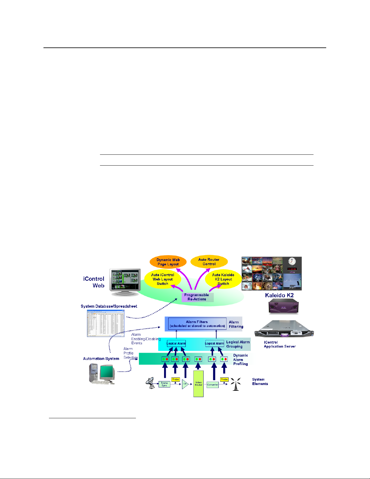
• iControl helps correlate alarms and data from multiple sources and devices by dynamically
displaying only the elements associated to a particular service or location, whether
upstream or downstream. This can greatly help operators in assessing fault conditions and
their consequences.
Extensive third-party device control and monitoring by SNMP and embedded applications
• A high level of device control and monitoring for a wide range of devices and
manufacturers is available with iControl, covering all essential television distribution and
broadcast applications
• Interfacing to third-party devices is achieved by combining industry standard SNMP
control protocols with feedback from full motion and high quality streaming video.
• iControl can also control third party devices using embedded control applications, and
these can be automatically presented to the operator by device alarms to speed response
times.
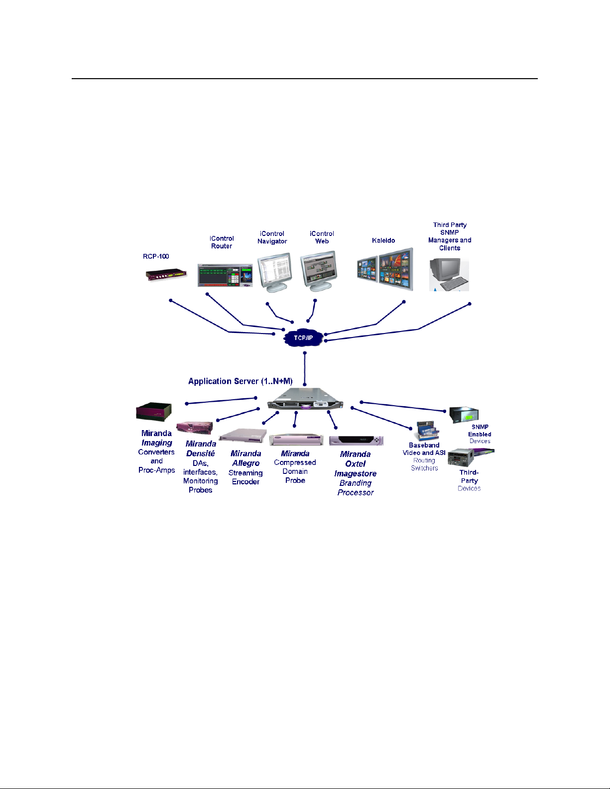
Operational Overview
The diagram below shows the relationship between the elements of an iControl system, and
how they work together to provide real time monitoring of a signal path.
4
Page 15

iControl
User Guide
User Interface
Once the iControl system is up and running, monitoring data and live audio/video streams are
automatically presented to operators via custom Web pages. Operators have access to current
and historical information on every device and signal being monitored.
Example of a customized iControl User Interface
5
Page 16

Introduction to iControl
How iControl Works
Example of a customized iControl User Interface
Example of a customized iControl User Interface
How iControl Works
The central element of any iControl system is the iControl Application Server. The Application
Server is a compact, 1 RU server that interfaces to video, audio and other hardware through a
variety of configurable ports (RS-232, RS-422, Ethernet), and connects to a local LAN over
TCP/IP.
iControl runs in a distributed network environment. Devices to be monitored or controlled are
either directly connected to the iControl Application Server, or accessible over a
TCP/IP connection. Each iControl Application Server runs several device control services, as
well as a lookup service.
Multiple Application Servers can coexist on a network, allowing large-scale distributed
systems to be defined and controlled. Using a Web browser, multiple users can connect to any
Application Server from any convenient desktop or portable computer.
On your client PC, you may launch any of the iControl components from a single user interface
called the iControl Launch Pad. The iControl Launch Pad may be downloaded to your
client PC from your Application Server.
6
Page 17

iControl Launch Pad
Components of iControl
iControl consists of a set of software components, the principle ones being:
• iC Navigator (see "iC Navigator", on page 8)
• iC Router Control (see "iC Router Control", on page 11)
iControl
User Guide
• iC Creator (see "iC Creator", on page 11)
• iC Web (see "iC Web", on page 12)
Each of these core components can be started from iControl Launch Pad, which is a clientside application downloadable from the iControl—Startup page.
There are three other core iControl components, important for system administration, and the
smooth, integrated operation of iControl as a whole. You can link to pages dedicated to their
functions from the iControl—Startup page. These other components are:
• iControl—admin (see "iControl—admin Page", on page 13)
• iControl—License management (see "License Management", on page 85)
• iControl—Reports (see "iControl Reports", on page 130)
7
Page 18
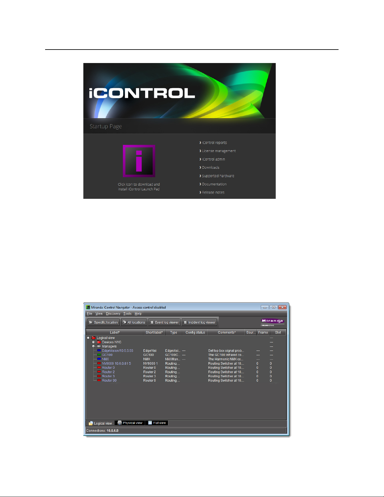
Introduction to iControl
iC Navigator
iControl—Startup Page
iC Navigator
iC Navigator is used to view, control and monitor Grass Valley and associated third-party
devices. This application provides users with direct access to the control windows of all
devices on an iControl network. Users can easily configure parameters, monitor functionality,
pinpoint problems, and track errors. It supports administrative tasks such as status reporting
and event logging.
iC Navigator presents devices and services in a hierarchical view. The tree-like structure lists all
recognized devices and services along with descriptions, including name, type, associated
comments, configuration status, frame and slot number.
iC Navigator
8
Page 19
iControl
User Guide
iC Navigator lets users display device-specific control windows. Icons at the top of the control
window provide a quick status indicator of key parameters. Color-coding enables operators
working locally or remotely to quickly identify the operating status of a device or service. From
iC Navigator, they can also display a configuration log panel for each device or service, which
highlights error conditions.
iC Navigator also provides access to a Log Viewer (via the General Status Manager (GSM)—see
below), which displays up to 100,000 of the most recent messages.
Note: Displaying more than 10,000 messages in the Log Viewer may require system
adjustments to maintain acceptable performance levels.
iC Navigator leverages industry standard SNMP protocols, and can fully integrate third party
control applications to create a complete facility-monitoring environment. With automated
reactions to failures, and guided operator responses, the system can deliver dramatically
reduced down times.
iC Navigator Views
Sorting allows you to determine the way in which devices will be arranged for display in
iC Navigator. Three views are available:
• Logical View arranges the devices in groups created by the user. Devices are sorted into
groups, and within each group, arranged in alphabetical order. Ungrouped devices are
displayed at the end of the list. Empty slots are not shown (unless they are in the Reference
Config).
Note: The grouping is done on the Application Server, and therefore, changes
apply for all users.
9
Page 20
Introduction to iControl
General Status Manager (GSM)
• Physical View arranges the devices relative to their physical connections and network
location. All frame slots are shown, even if they are empty. This is done automatically by
the system. Devices are sorted by:
• the IP address of the iControl server,
• then the serial communication port of the server where the (Imaging) frame is
connected,
OR,
• the IP address of the Densité communicator,
• then the frame itself.
Once the frame folder is open, you can see the device by the slot when applicable.
Note: Physical View may only be applied to devices in frames.
• Flat View shows all devices in alphabetical order without any grouping.
With Logical View and Physical View, you can open and close folders in the list to display any
level of the hierarchy.
General Status Manager (GSM)
iC Navigator is also the front end for—and depends largely upon—an iControl service called
the General Status Manager (GSM). At least one GSM is always running on an Application
1
Server on a given network
. It acts as a central clearing station for device discovery and alarm
status.
1. To be more specific, on each subnet in a network being monitored by iControl there must be at least one
Application Server with an active GSM.
10
Page 21
iControl
User Guide
All iControl alarm notifications are managed through a central GSM. Alarm notifications from
multiple distributed GSMs are managed by the multi-GSM Manager, which computes the
virtual alarm, gets its status and dispatches the alarm status to the client.
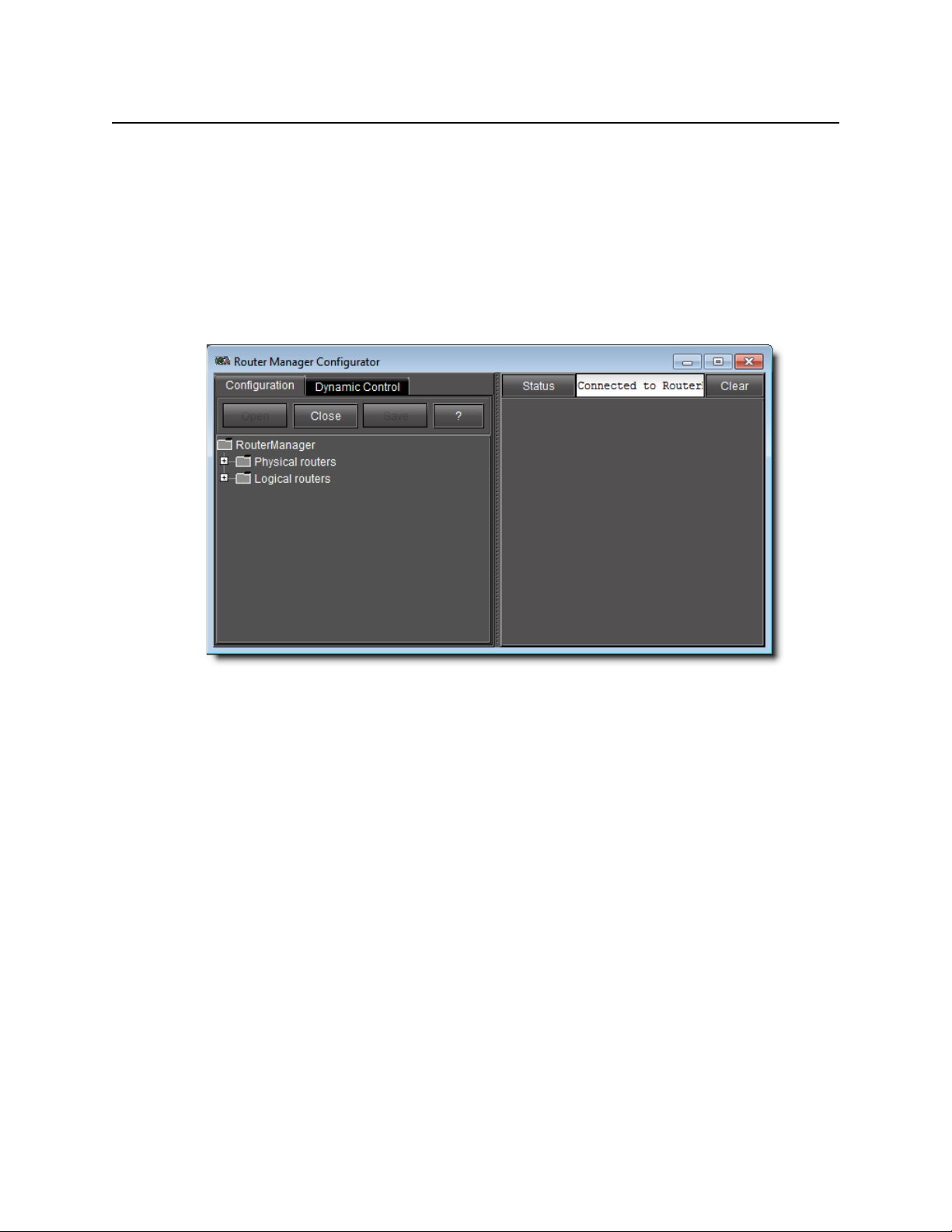
iC Router Control
iC Router Control provides advanced router control and status monitoring via a flexible
graphical user interface. With protocol and driver support for many router models, iC Router
Control software can be configured to manage multiple routers from multiple vendors from a
single user interface.
iControl Router Manager Configurator
iC Router Control works over regular IP networks, so that multiple users can monitor and
control several routers, even from remote locations. Users can create virtual routing
environments where physical router resources are deployed and controlled by software in
customized configurations optimized for operational needs.
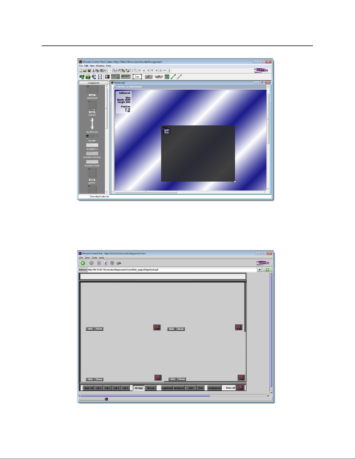
iC Creator
iC Creator is the application used to create iC Web sites. The pages of these Web sites provide
a user-friendly interface for operators to control and monitor devices connected throughout
the iControl environment. With iC Creator, users can build multiple representations of their
networks and facilities using a simple drag-and-drop drawing editor. Objects that you create
in iC Creator can be saved as widgets, and then re-used on other pages.
11
Page 22
Introduction to iControl
iC Web
iC Creator is used to build monitoring and control Web sites
iC Web
iC Web is a custom Web browser used to access iC Web sites hosted on an Application Server.
It is sometimes referred to as the runtime mode of iC Creator.
12
iC Web site viewed using iC Web
Page 23
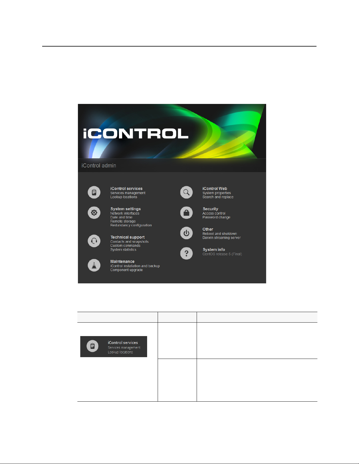
iControl—admin Page
The iControl—admin page is a sub-area of the iControl main site, and is devoted to
administrative configuration. Everything accessible within the iControl—admin page is
password-protected. The following is a list of administrative tools available within the
iControl—admin page:
iControl
User Guide
iControl—admin page (see table, below, for descriptions)
iControl—admin
Sub-category Tool name Tool description
iControl Services iControl Services
page tools
Management
Lookup
Locations
Used to start, stop and display the status of iControl services
(e.g. GSM, Router Manager Service, RMI Daemon). Also used
to load balance Densité Managers, configure serial ports, to
start/stop lookup services, and to view a system profile of the
Application Server.
iControl uses a lookup service to get information about
remote programs or machines, and uses that information to
establish communications. In this way, cards, frames and
other devices make their presence known on an iControl
network, and participate in monitoring and control
operations.
13
Page 24
Introduction to iControl
iControl—admin Page
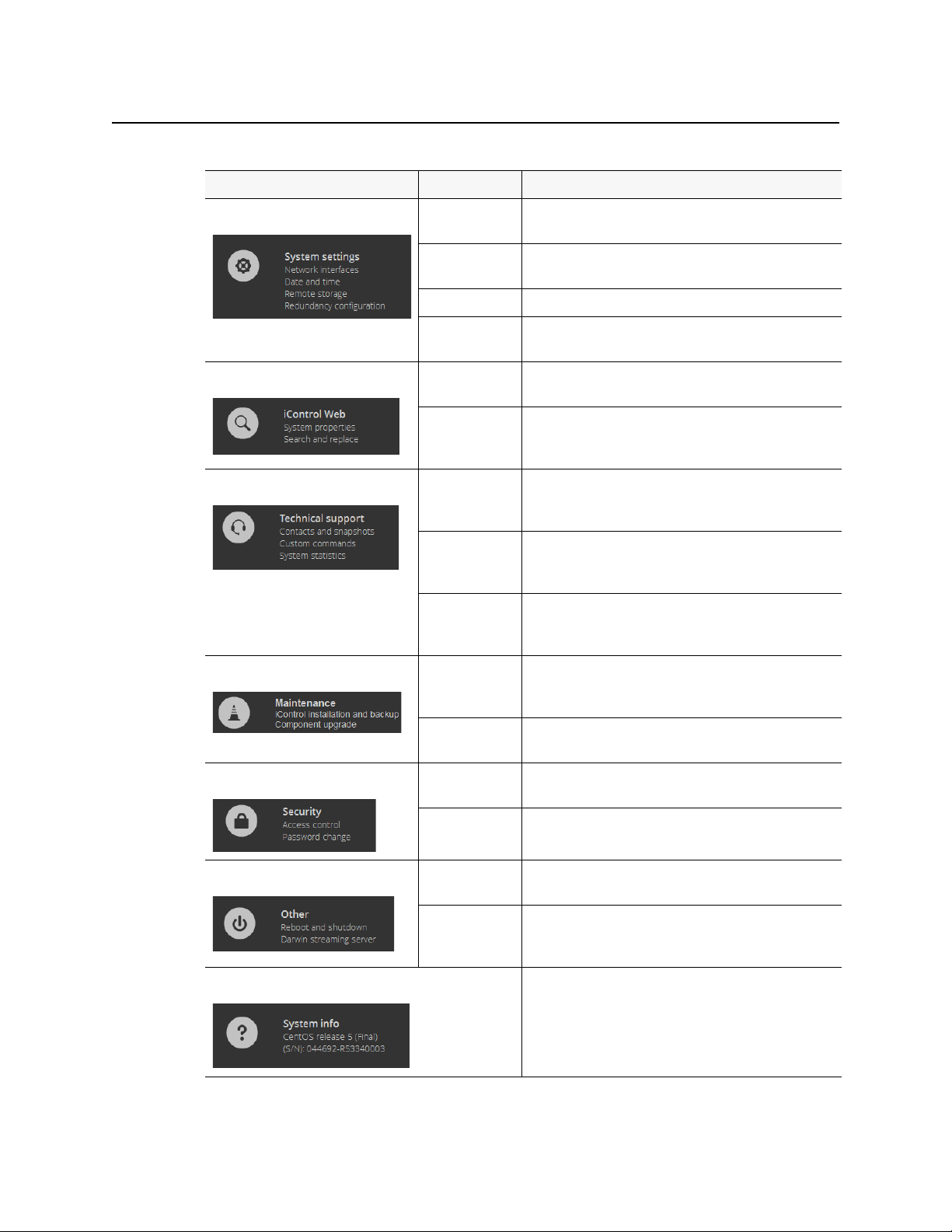
iControl—admin
Sub-category Tool name Tool description
System Settings Network
iControl Web System
Technical Support Contacts and
page tools
(Continued)
This page has links to other pages that allow you to configure
Interfaces
Date and Time Used to set the system’s date and time, time zone, and either
Remote Storage
Redundancy
Configuration
Properties
Search and
Replace
Snapshot
Custom
Command s
an Application Server for network operations.
enable or disable NTP synchronization.
Used to set up N+1 redundancy configurations for
Application Servers.
Used to change (search and replace) a specific attribute in
multiple iControlWeb (iC Web) pages on an Application
Server.
Contact information (by region) for Grass Valley Technical
Support and a utility application to create a system snapshot
if one is required by Technical Support.
Behaves as front end to the execution of a collection of
custom scripts, and is primarily used for troubleshooting
problems on an Application Server.
System Statistics Provides links to statistics and graphs that can be used to
monitor and troubleshoot the performance of an
Application Server.
Maintenance iControl
installation and
backup
Component
Upgrade
Security Access Control Used to ena ble security, to run LDAP se rvices, and to manage
Password
Change
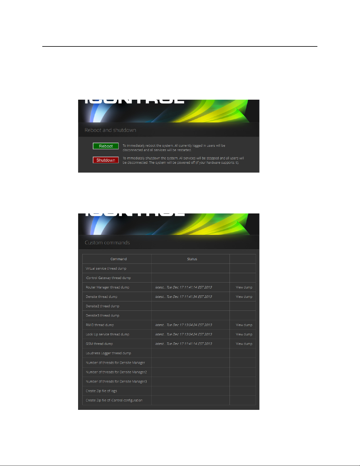
Other Reboot and
Shutdown
Darwin
Streaming
Server
System info Indicates the current operating system of the Application
Used to install iControl software, back up data and
configuration files, and restore iControl configuration data
from a backup file.
Used to upgrade iControl components, as well as to roll back
iC Web sites and SNMP Drivers.
base domains on an Application Server.
Used to change the passwords of users.
Used to reboot or shut down an Application Server.
Allows an Application Server to provide real-time streaming
of video thumbnails. This page is primarily used to start or
stop the Darwin Server.
Server.
14
Page 25
iControl
User Guide
This page contains links to most of the functionality that you will use to administer iControl on
a regular basis.
Reboot and Shutdown
This page is used to reboot or shut down an Application Server.
Custom Commands
This page acts as front end to the execution of a collection of custom scripts, and is primarily
used for troubleshooting problems on an Application Server.
15
Page 26
Introduction to iControl
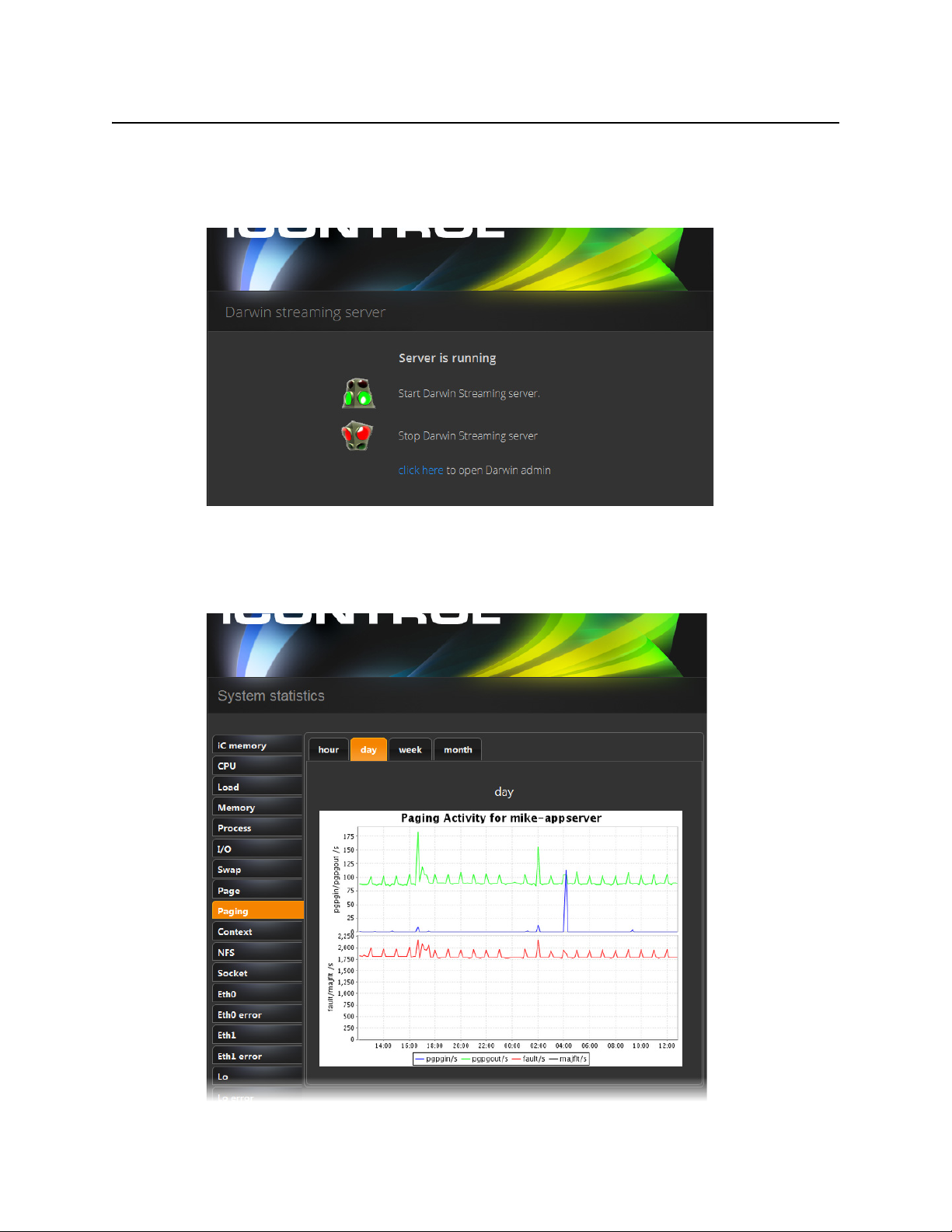
Darwin Streaming Server
Darwin Streaming Server
The Darwin Streaming Server allows an Application Server to provide real-time streaming of
video thumbnails. This page is primarily used to start or stop the Darwin Server.
System Statistics
This page provides links to statistics and graphs that can be used to monitor and troubleshoot
the performance of an Application Server.
16
Page 27

iControl Services
iControl Services are software components that support (or make additional functionality
available to) iControl. These services are described in the table below:
iControl services
Service Description
Imaging Communicators Software components used to configure and control Grass Valley Imaging-series frames
Densité Communicators Software components used to configure and control Grass Valley Densité frames
Kaleido/Oxtel Communicators Software components used to configure and control Grass Valley Kaleido and Oxtel
Gateway Software component that enables third party applications to monitor and control Grass
GSM (General Status Manager) Software component used for central management of all alarm conditions and error
Virtual Service Managers Software components used for configuring and controlling Grass Valley proc amp
iControl
User Guide
devices
Valley devices. It is also used to connect an RCP-100 or RCP-200 Remote Control Panel
to iControl and to provide line selection from the iC Web player Densité-series cards
scope option
logging
devices and composite panels
SNMP
Router Manager Software component used for configuring and controlling routing switchers
In addition, services providing interfaces to third party devices are available as options. These
services include VTR and IRD (Integrated Receiver Decoder) devices.
SNMP (Simple Network Management Protocol) has emerged as an important standard in the
broadcast industry, allowing broadcasters to monitor the equipment from multiple vendors
using a single, IP-based protocol. iControl provides SNMP support in two distinct and
important ways.
iControl acts as an SNMP manager by reading the status of third party devices that support
SNMP and have published their SNMP MIB (Management Information Base). It augments the
status information using streaming video, audio and scope telemetry data gathered using
Densité Series cards and the Allégro Streaming Encoder/Server.
In those cases where a third party SNMP management application is deployed, iControl acts as
an SNMP agent reporting errors and status to the SNMP manager using the SNMP protocol
and its own SNMP MIB.
For devices that do not provide IP connectivity, the iControl Application Server acts as an
SNMP translator and provides SNMP Agent functionality. The Application Server receives
status information from the devices using their existing protocols, and will issue SNMP TRAPS
and respond to SNMP
GET messages on behalf of the devices below it. The Application Server
further enhances SNMP Agent capability by allowing users to create virtual alarms, which can
be enabled or disabled according to a schedule, or slaved to an automation system.
17
Page 28

Introduction to iControl
iControl Integration with Other Grass Valley Products
Note: Grass Valley devices that provide IP connectivity at the frame—such as
Densité and Kaleido—offer direct SNMP support, allowing third party SNMP
Manager applications to get status information using an SNMP
GET command.
iControl Integration with Other Grass Valley Products
Grass Valley products are, naturally, tightly integrated with iControl, and are often found in
networks where iControl has been installed. Some of the more popular Grass Valley products
are described below.
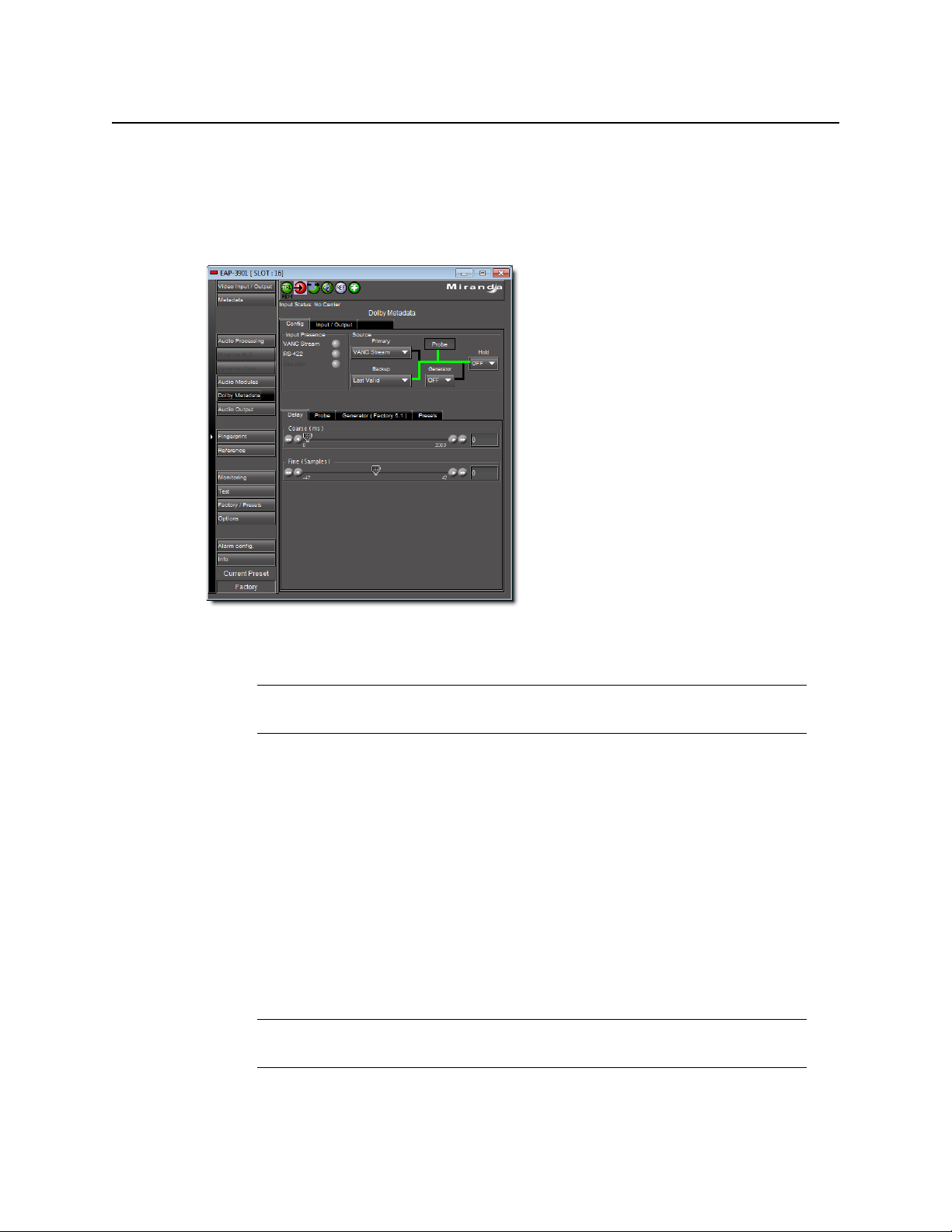
Control Windows and Device Parameters
To control device parameters, double-click the device in the navigation pane to display the
control window for that device. Or right-click the device and select Show Control window
from the pop-up menu.
The device name is listed along the top of each control window along with the “status icon” for
the device. Icons in the upper left corner of the control window (again depending on the
device type) provide a quick status indicator of key parameters such as the Operational or Test
Mode, Input Status, or Reference Status. This is called the “status dashboard”.
On each control window, there are different selector tabs that correspond to different groups
of parameters for each device. When working with control windows, you begin by selecting
the tab to display the parameters for a particular group (see "Control window parameters",
on page 19).
Note: If you try to display the control window for a device and you get the message
Control window
implemented as a controllable device by iControl. Therefore, you can only see the
status of this device but cannot configure any control parameters.
Not Available, this means that this device type has not been
18
When one or more Control windows are open, the View menu item Close All Control
windows becomes available, and the menu lists the device names of open control windows
for selection.
Page 29

iControl
User Guide
Each device in the system is controlled via a control window. The control window is an
operational window for the selected device, which you display to control the device.
Parameters vary according to the type of device, although the Info parameters are common to
all devices.
To access the control window for a device, double-click the device in the iC Navigator display,
or right click and select Show Control window from the pop-up menu.
Control window parameters
Control windows are specific to the device type. Following are examples of control window
selector tabs and their associated parameters:
Selector tab Sample parameters
Config Audio destination, Audio source, Audio Delay, No signal delay, Signal standards detection, No signal
delay, Scan, VBI, Video.
Info Comments, Device Type, Label, Long ID, Manufacturer, Remote system administration, Service Version,
Short Label, Source ID, Vendor.
Video Player, Thumbnail streaming, Streaming priority control, Waveform monitor and vector scope.
Timing Horizontal fine, Horizontal position, Horizontal Timing, Vertical Timing, Fine Timing Adjustments
Meta Aspect ratio, Copy control information, Source.
With some devices, the control window includes the button Load Factory which resets the
parameters on the window group to their original factory values.
Info Control Panels
Info control panels display parameters for individual devices, and is available for all device
types. The Info control panel includes device identification information such as the label, short
label, type, comments, source ID, config status, frame, and slot. You can display the Info
control panel from the device control window, or you can right-click the device in iC Navigator
and select Show info control panel.
From the info control panel, you can change the name of the selected device, as well as, type
comments. By default, the device name takes the type identification; however, you will find it
helpful to rename devices using user-specific names. Once you change the device name in the
control window, the name of the item is also changed in the iC Navigator display, making it
easier to locate.
From the info control panel, you can also register the service to a remote Application Server
using Remote system administration.
Densité
Grass Valley’s Densité-series products are rack-mountable frames that house a variety of
compact cards used for infrastructure interfacing and distribution. Operators can see the
signals they are controlling using advanced visual monitoring over IP features integrated in the
processing modules. Feedback in the form of integrated streaming thumbnails and
19
Page 30

Introduction to iControl
Imaging Series (Symphonie & Quartet)
waveform/vectorscopes provides much easier and highly cost effective control and
monitoring of signals.
Remote control options for the Densité series include a traditional remote control panel
(RCP-100, RCP-200), and a stand-alone PC-based control application called iControl Solo. More
advanced control over IP is provided by iC Web.
The full range of video and audio signal parameters and alarms provided by Densité probes
can be extracted and displayed using alarm panels in iC Web. With iControl’s advanced alarm
management, operators can choose to display specific device alarms. Alternatively, users can
build their own alarms by choosing from an endless combination of signal and device
conditions and external triggers. Users can choose to be alerted only on specific criteria.
Imaging Series (Symphonie & Quartet)
Grass Valley’s Imaging-series products are rack-mountable frames that house a variety of fullsize cards used for a wide range of interfacing and distribution functions. Two frames are
available: the Symphonie, which can accommodate up to 16 cards, and the Quartet, which
holds four cards.
Notable among the many Imaging cards available is the XVP family, which offers advanced
processing and noise reduction for incoming SD and HD feeds. A single XVP card offers up,
down, and cross conversion plus frame synchronization and 16 channel audio processing.
The Imaging Series combines rich processing functionality with high image quality, along
with several remote control options.
Kaleido
Grass Valley’s Kaleido product line provides multi-image processing and router functionality in
a single, expandable chassis. Fully integrated with iControl, they are ideal for advanced
monitoring applications, such as multi-channel playout centers.
20
• The Kaleido-X (7RU) is a multi-room, multi-image processor and router. Each chassis can
display 96 HD, SD or analog inputs any number of times, in any size, across 8 displays of
any resolution and orientation. As a router, it offers switching of 96 unprocessed inputs
to 48 HD/SD outputs for feeding monitors, test equipment and master control or
production switchers.
Page 31

iControl
User Guide
• The Kaleido-X (4RU) is a multi-room, multi-image processor. Each chassis can
display 32 HD, SD or analog inputs any number of times, in any size, across 4 displays of
any resolution and orientation.
• The Kaleido-X16 is a 1RU, multi-image display processor. Each chassis can display up to 16
auto-sensing HD, SD, or Analog inputs that can be displayed across two high resolution
outputs at multiple sizes.
• The Kaleido-K2 is a 32-input advanced, modular multi-image display processor. Fully
integrated with Grass Valley’s master control switching and infrastructure monitoring
systems, it is designed to simplify HD/SD broadcast monitoring requirements.
• The Kaleido-Alto-HD is a 10-input multi-image display processor. It features auto-sensing
HD SDI, SDI, and analog composite video inputs, and a high-quality DVI output with up to
1920 × 1080 or 1600 × 1200 pixels.
• The Kaleido-Quad-HD is a high-quality quad-split multi-image display processor designed
for monitoring applications demanding fewer inputs. It features 4 auto-sensing HD SDI,
SDI, and analog composite video inputs, and a high-quality DVI output with up to
1920 × 1080 or 1600 × 1200 pixels.
• The Kaleido-Quad-Dual combines two independent, high-quality quad-split multi-image
display processors in a single 1RU frame for optimal space efficiency. The processor
has 2 x 4 auto-sensing HD-SDI/SDI/ Analog Composite video inputs, and 2 high-quality DVI
outputs with up to 1920 × 1080 or 1600 × 1200 pixels.
Imagestore
Allégro
Grass Valley’s Imagestore devices deliver high performance, HD/SD master control switching
with HD/SD branding graphics capabilities, along with 5.1 audio mixing and storage. They
offer video and multi-channel audio mixing plus audio playout. High impact channel
branding and promotional graphics can be inserted by multiple independent keying layers.
Each Imagestore processor features independent HD/SD preview, clean-feed and auxiliary
outputs. The Imagestore series supports serial or Ethernet automation via a single interface.
Integration with iControl is achieved using the widely supported Oxtel protocol.
Grass Valley’s Allégro is a 1 RU streaming encoder/server that allows real-time confidence
monitoring of remote signals. It combines encoder and server functions to enable low latency
streaming of video, audio and data over a standard IP network. Fully adapted to the
monitoring of critical broadcast signals, it integrates telemetry such as signal presence, VBI
extraction and audio level metering.
Multiple Allégro encoders can be managed remotely from a central location. Up to 16 local
and remote player clients can monitor the same signal. Streaming video for Allégro can be
fully integrated into iC Web, iC Router or Kaleido series products to optimize operator
effectiveness. With Allégro’s practical Quick Start menu and Web-based graphical user
interface, only a few clicks are required to get the unit ready for operation.
21
Page 32

Introduction to iControl
What’s New in Version 6.02
What’s New in Version 6.02
Building on the success of previous versions, iControl version 6.02 is an important new release
of Grass Valley’s system for monitoring and control over IP. It reinforces the established
position of iControl as the industry standard for video network management. With its highquality streaming video, comprehensive support for all signal formats, and tight integration
with other vendors’ equipment and monitoring systems, iControl reduces mean-time-torepair by enabling end-to-end monitoring of even the most complex operations.
Audio Loudness Analyzer
[ICONTROL-18307] iControl version 6.02 introduces an enhancement to the existing
Loudness Analyzer offering. Now—with the introduction of the new
LoudnessAnalyzerScriptable object—you can script the integration of the Loudness
Analyzer application into iControl Web pages. This is accessible via the global variable
loudnessAnalyzer.
See also
For more information about scripting with the
the Script help in iC Creator, on the Help menu.
LoudnessAnalyzerScriptable object, see
Backup and Restore
[Ref. #ICONTROL-16411] iControl version 6.02 enhances its Backup and Restore functionality
with the ability to schedule automatic backups of configuration data.
See also
For more information, see "Scheduling Automatic Backups of an Application Server"
on page 475.
Client PC Operating System
[ICONTROL-18004] As of version 6.02, iControl supports both Windows 8 and Windows 7 on
the client PC.
Note: iControl no longer supports Windows XP on the client PC.
Densité Services
[Ref. #18308] The following Densité cards have package updates available in this release
(iControl version 6.02):
• ADX-3981
•AMX-1881
•AMX-3981
•DCO-1781
22
Page 33

User Guide
• EAP-3101
• EAP-3901
• FIO-911-4R
• FIO-911-4T
• FRS-3901
• HCP-1801
• HLP-1801
• IRD-3101
• IRD-3801
• KMX-3901-IN
• KMX-3901-OUT
• SCO-1421
• SME-1901
• SME-3101
•XVP-3901
See also
For more information, see the “Densité Series Cards” section of the “Release Notes” chapter
of the iControl Version 6.02 Release Notes.
iControl
Supported Devices
See also
For more information about requesting licenses and activating support (in the case of iControl
options) for any below-mentioned devices, see "License Management" on page 85.
iControl introduces support for the following devices:
[Ref. #DRIVER-40] Harmonic Proview 7000.
[Ref. #DRIVER-175] CPI TL22CI Amplifier.
[Ref. #DRIVER-176] Radyne DM240XR.
[Ref. #DRIVER-177] Logic Innovations RS-1100.
[Ref. #DRIVER-178] Logic Innovations IPE-4000-5.
[Ref. #DRIVER-179] Cisco PowerVu Network Center.
[Ref. #DRIVER-180] Evertz 7867VIPA-DUO.
[Ref. #DRIVER-182] Motorola DSR4440.
[Ref. #DRIVER-183] PBI DCH4000P Receiver.
[Ref. #DRIVER-184] Sumavision EMR D8020.
[Ref. #DRIVER-191] Evertz 3405 Card.
[Ref. #DRIVER-192] Softel Vflex.
23
Page 34

Introduction to iControl
Web System Administration
[Ref. #DRIVER-195] SpectraLogic BOAT380 Tape Library.
[Ref. #DRIVER-207] Miteq NSU1 Switchover.
[Ref. #DRIVER-208] Miteq U9853-6-1K Modulator.
[Ref. #DRIVER-214] Cisco D9140 Multiplexer.
[Ref. #DRIVER-215] Cisco D9190 PCAM.
[Ref. #DRIVER-216] JDSU VSA API v2.
Web System Administration
[Ref. #ICONTROL-18387] iControl version 6.02 introduces several enhancements to the
Webbased administration of iControl. For Application Server administrative tasks, if you
log on to the iControl—admin page using the admin profile, you can create and delete
user profiles for server-side operations on the iControl—Admin users management page.
Additionally, you can import file-based lists of user profiles or else export iControl’s current
user profiles to a spreadsheet.
See also
For more information, see:
• "User Profile Management for Application Server Administration" on page 258
• "Managing Users for Server-Side Operations" on page 285
[Ref. #ICONTROL-18419] iControl now supports configuring several NTP servers as timing
sources for an Application Server. As before, one NTP server acts as the highest-priority
timing source. Upon the Application Server’s inability to reach the highest-priority
NTP server or else to properly resolve the timing signal, the next NTP server in the priority
queue becomes the new timing source.
See also
For more information, see "Configuring an Application Server’s Date and Time" on page 65.
24
Page 35

Summary
Getting Started with iControl
Overview
Key Concepts
Getting Started Workflow
Network Considerations & Port Usage
Overview
The iControl Application Server is shipped in a default configuration, with its eth0 port turned
on. In order for it to be able to join a network, it must have its network settings modified. For
example, the default IP address and subnet mask must be changed to values that will work on
your network.
. . . . . . . . . . . . . . . . . . . . . . . . . . . . . . . . . . . . . . . . . . . . . . . . . . . . . . . . . . . . . . . . . . . . . . . . . . 25
. . . . . . . . . . . . . . . . . . . . . . . . . . . . . . . . . . . . . . . . . . . . . . . . . . . . . . . . . . . . . . . . . . . . . . 29
. . . . . . . . . . . . . . . . . . . . . . . . . . . . . . . . . . . . . . . . . . . . . . . . . . . . . . . . . . 44
. . . . . . . . . . . . . . . . . . . . . . . . . . . . . . . . . . . . . . . . . . . . . . . 73
Page 36

Getting Started with iControl
Overview
26
Flowchart for configuring SNMPv3 on an SNMP agent Application Server
Page 37

iControl
User Guide
IMPORTANT: Ethernet Port Label Considerations
Please read the section regarding Ethernet port labels (see "Ethernet Port
Labeling on the R200, R210, R310, and R320 Application Servers", on page 49).
This is done by connecting a client PC directly to the Application Server, using a crossover
Ethernet cable. You will be able to connect to the Application Server from the client PC using a
standard Web browser. A series of Web pages will permit you to make the necessary changes.
Once the network settings are configured, you will be able to connect the Application Server
to the LAN containing the devices to be monitored and controlled.
27
Page 38

Getting Started with iControl
Release Notes
You can access an iControl Application Server from a Windows workstation by using a Web
browser, such as Microsoft Internet Explorer or Mozilla Firefox. Some tasks can be
accomplished on the Application Server via a Web interface. For other functionality, you can
download iControl client applications directly from the Application Server.
We recommend that you install the iControl Application Server on a dedicated LAN along with
the equipment it is intended to monitor, using the existing security infrastructure. A qualified
system administrator should verify that the setup follows your organization’s security
standards.
Release Notes
The Release Notes shipped with your iControl system contain important information on
iControl system requirements, the latest features, performance tips, and known issues. A hard
copy is shipped with each system, along with a copy in PDF format on the documentation CD.
The Release Notes can also be downloaded from an iControl—Startup page (see "Starting
iControl", on page 552).
Upgrading iControl
Instructions for performing an upgrade of an existing iControl system to version 6.02 are
provided in the iControl Upgrade Guide, which is available from Grass Valley Technical Support
(see "Contact Us", on page 599).
Recommendations for System Optimization
Here are some guidelines for optimizing performance and balancing the load on an iControl
system:
28
Page 39

• Where a large number of devices are being monitored, consider setting up multiple GSMs
(one per Application Server).
• Run a maximum of three Densité Managers on an Application Server.
• Allocate a maximum of 150 streams per Densité Manager. A typical Densité frame
containing 10 DEC cards and 10 UAP cards creates 30 streams, whereas a Densité frame
with SCP cards generates 22 streams.
• Assign a maximum of five Densité frames to a Densité Manager.
Redundancy Planning
While iControl Application Server failures are not common, it is prudent to plan for such an
eventuality. Fortunately, recovery from a hardware failure can be ensured by the use of one or
more standby Application Server(s). A standby server takes over all the system monitoring and
control processes that were running on a main Application Server prior to a failure.
Additionally, unexpected power disruptions, such as might occur during a power failure, can
damage the file system on an iControl Application Server. It is strongly recommended that all
Application Servers be connected to a standby power source, such as a UPS (Uninterruptible
Power Supply), as a preventive measure.
iControl
User Guide
Before putting your Application Server into operation, you should consider implementing a
redundancy plan. A redundancy plan defines the use of standby Application Servers in case of
hardware failure. This ensures that all the processes that run on the main server(s) will
continue to operate uninterrupted.
Redundancy (or recovery) planning is best done at the same time as the system set-up. Full
redundancy requires one standby server for each running Application Server. More typically,
an iControl system includes one standby server for every five primary Application Servers,
since it is unlikely that more than one will fail at the same time.
IMPORTANT: If you require assistance with your recovery planning, please contact Grass Valley
See also
Key Concepts
Lookup Services
Technical Support (see "Contact Us", on page 599).
For more information, see:
• "Application Server Auto-failovers and Manual Takeovers" on page 465.
• "Configuring and Managing Application Server Redundancy" on page 477.
iControl—and Grass Valley products in general—use a lookup service to get information on
remote programs or machines, and use that information to establish communications. In this
way, cards, frames and other devices can make their presence known on an iControl network,
and thus can participate in monitoring and control operations.
29
Page 40

Getting Started with iControl
Service and Alarm Discovery Lookup Table
By default, each Application Server runs a lookup service that registers and makes available
information about the devices on its network. It will also register with all lookup services that
are running on other Application Servers on the same LAN.
Note: Displaying more than 10,000 messages in the Log Viewer may require system
adjustments to maintain acceptable performance levels.
When client PCs are on different subnets, or when multiple Applications Servers are involved,
the locations of lookup servers must be properly specified in order for operators to be able to
(a) access iControl monitoring Web pages using iC Web, and (b) use iC Navigator to view
iControl alarms and control panels.
On the iControl Lookup locations page, there are two areas representing two distinct lookup
tables.
Service and Alarm Discovery Lookup Table
As a default, an Application Server’s client applications, such as iC Navigator and iC Web,
discover services and alarms originating from Application Servers on the local subnet. Leaving
the Service and alarm discovery table empty results precisely in this behavior with no need
for further configuration.
IMPORTANT: System behavior
If the Service and alarm discovery table of Application Servers is empty, client
applications on the local Application Server can see services and alarms coming
from the local GSM and all active GSMs on Application Servers within the
subnet.
If, however, you would like an Application Server’s client applications to see services and
alarms from Application Servers OUTSIDE the local subnet, you must include the IP addresses
of these external servers in the Service and alarm discovery table.
30
Page 41

iControl
User Guide
Populated Service and alarm discovery table (circled)
IMPORTANT: System behavior
If there are Application Servers listed in your Service and alarm discovery table
and you would like for client applications to see services and alarms hosted by
the local Application Server as well, you must include the IP address of the local
Application Server in this list.
See also
For more information, see "Examples: Service and Alarm Discovery Scenarios" on page 32.
31
Page 42

Getting Started with iControl
Alarm Publication Lookup Table
Alarm Publication Lookup Table
Services, such as Densité Manager, automatically publish their alarms on GSMs within the
same subnet as the Application Server hosting the service. However, if you would like alarms
to be visible to a GSM outside the local subnet, you must specify the IP address of the external
Application Server (the server hosting the lookup service where the target GSM is registered)
in the Alarm publication table of the iControl Lookup locations page.
Populated Alarm publication table (circled)
IMPORTANT: System behavior
If the Alarm publication table of Application Servers is empty, the Densité
Manager on the local Application Server publishes its alarms exclusively on the
local GSM and active GSMs on Application Servers within the subnet.
If the Alarm publication table is populated with the IP address of a non-local
Application Server, and you would like the local GSM to see alarms originating
from the local Densité Manager, you must also include the IP address of the local
Application Server.
See also
For more information, see:
• "Examples: Alarm Publication Lookup Scenarios" on page 37.
• "About the Alarm Publication Lookup Table" on page 42.
Examples: Service and Alarm Discovery Scenarios
The way in which lookup services are configured varies from one installation to another. The
examples on the following pages demonstrate the basic concepts, and can serve as a guide as
you set up your own iControl network.
32
Page 43

iControl
User Guide
Example 1 — Single Application Server
In a typical, basic iControl configuration, only one Application Server is needed to handle all of
the iControl functions. Any TCP/IP devices associated with the Application Server are on the
same subnet.
1. Since Alpha is the only Application Server on Subnet A, its Lookup Service should be ON.
2. The GSM is active on Alpha.
3. Since Alpha is the only Application Server on Subnet A, it is not necessary to type anything
in the Service and alarm discovery area.
33
Page 44

Getting Started with iControl
Example 2 — Two Application Servers, Same Subnet
IMPORTANT: System behavior
If the Service and alarm discovery table of Application Servers is empty,
client applications on the local Application Server can see services and
alarms coming from the local GSM and all active GSMs on Application
Servers within the subnet.
4. When iC Navigator (or any client application) is downloaded from Alpha by this PC, the
application will perform a multicast discovery within Subnet A, find the Alpha Lookup
Service, and then be able to see all devices and services registered on Alpha.
5. If this PC has access to Subnet A (e.g. via VPN), it can access Alpha’s iControl—Startup page
from a Web browser, and download iC Navigator (or any client applet). The application
knows about the Lookup Service on Alpha, and so the client PC will be able to see all devices
and services registered on Alpha.
Example 2 — Two Application Servers, Same Subnet
As an iControl configuration grows, additional Application Servers can be added to handle the
increased workload. Any TCP/IP devices associated with either Application Server should be
on the same subnet.
34
Page 45

iControl
User Guide
1. For the purpose of this example, Alpha is the only Application Server running the Lookup
Service. Under actual conditions, you should have two Application Servers (per subnet)
running the lookup service to provide redundancy.
2. The GSM is active on Alpha.
3. It is not necessary to type anything in Alpha’s Service and alarm discovery area. The
discovery process will automatically result in all devices and services on Subnet A
registering with Alpha’s Lookup Service.
IMPORTANT: System behavior
If the Service and alarm discovery table of Application Servers is empty,
client applications on the local Application Server can see services and
alarms coming from the local GSM and all active GSMs on Application
Servers within the subnet.
4. In order to share the monitoring workload, the GSM is active on Bravo.
5. As mentioned above, the discovery process will result in all devices and services on
Subnet A automatically registering with Alpha’s Lookup Service. So it would not ordinarily
be necessary to type anything in Bravo’s Service and alarm discovery area. This is not true,
however, when Bravo is accessed by a client PC from another subnet (see below).
6. When iC Navigator (or any client application) is downloaded from Alpha by this PC, the
application will perform a multicast discovery (see "Multicasting vs. Unicasting",
on page 40) within Subnet A, find the enabled Alpha Lookup Service, and then be able to
see all devices and services registered on both Alpha and Bravo.
7. If this PC has access to Subnet A (e.g. via VPN), it can access Alpha’s iControl—Startup page
from a Web browser, and download iC Navigator (or any client applet). The application
knows about the enabled Lookup Service on Alpha, and so the client PC will be able to see
all devices and services registered on both Alpha and Bravo.
If, however, the PC’s Web browser is pointed to Bravo’s iControl—Startup page, and
downloads a client application, the applet will not automatically detect the lookup service
on Alpha, and so none of Bravo’s services or devices will be visible on the client PC. In order
to enable direct access, type Alpha’s IP address in Bravo’s Service and alarm discovery
area—the application will be able to find the lookup service, and therefore see everything
on Subnet A.
Example 3 — Multiple Application Servers on Different Subnets
It is common in larger iControl configurations to have multiple Application Servers on
different subnets. Lookup services allow Application Servers from one subnet to share
information with Application Servers on another subnet.
35
Page 46

Getting Started with iControl
Example 3 — Multiple Application Servers on Different Subnets
36
1. For the purpose of this example, Alpha is the only Application Server running the Lookup
Service on Subnet A. Under actual conditions, you should have two Application Servers (per
subnet) running the lookup service in order to provide redundancy.
2. A GSM is active on Alpha.
3. The discovery process will result in all devices and services on Subnet A automatically
registering with Alpha’s Lookup Service. If a client PC opens iC Navigator from Alpha, all
Subnet A devices and services will be visible in iC Navigator.
4. As mentioned above, as a result of the discovery process, all devices and services on
Subnet A will automatically register with Alpha’s Lookup Service. So it would not ordinarily
be necessary to type anything in Bravo’s Service and alarm discovery area. However, if a
Page 47

iControl
User Guide
client PC opens iC Navigator (or any client application) from Bravo, it will not see anything
unless there is an IP address (either Alpha’s or Charlie’s) entered in Bravo’s Service and
alarm discovery area.
IMPORTANT: System behavior
If the Service and alarm discovery table of Application Servers is empty,
client applications on the local Application Server can see services and
alarms coming from the local GSM and all active GSMs on Application
Servers within the subnet.
5. The discovery process will result in all devices and services on Subnet B automatically
registering with Charlie’s Lookup Service. If a client PC opens iC Navigator from Charlie, all
Subnet B devices and services will be visible.
6. If this client PC has access to Subnet A (e.g. via VPN), it can access Alpha’s iControl—Startup
page from a Web browser, and download iC Navigator (or any client application). The
application knows about the Lookup Service on Alpha, and so the client PC will be able to
see all devices and services registered on both Alpha and Bravo. Similarly, downloading an
application from Charlie would make all of the devices and services on Subnet B visible.
However, in order for that same client PC to be able to see services and devices from both
Subnet A and Subnet B, the IP addresses of both Alpha and Charlie, must be typed in each
other’s Service and alarm discovery areas.
Note: The order in which the IP addresses are typed is not important.
Examples: Alarm Publication Lookup Scenarios
Example 1 — Publishing Densité Alarms to all GSMs within the Local Subnet
If you want your local Application Server’s Densité alarms to be visible only to the GSMs within
the local subnet, you can leave the Alarm publication table of the local Application Server
unpopulated.
37
Page 48

Getting Started with iControl
Example 2 — Publishing Densité Alarms outside the Local Subnet
38
1. Alpha’s Lookup Service should be ON.
2. The GSM is active on Alpha.
3. Since, in this example, we only want Alpha’s Densité alarms to be visible within the subnet,
it is not necessary to type anything in the Alarm publication table.
Example 2 — Publishing Densité Alarms outside the Local Subnet
If you want your local Application Server’s Densité alarms to be visible to the GSM on an
Application Server outside the local subnet, you need to include the IP address of the external
(to the local subnet) server in the Alarm publication table of the local Application Server.
Page 49

iControl
User Guide
1. Alpha’s Lookup Service should be ON.
2. The GSM is active on Alpha, Bravo, and Charlie.
3. Since, in this example, you do not want Charlie to publish its Densité alarms outside its own
subnet, there is no need to populate its (Charlie’s) Alarm publication table.
4. Since, in this example, you do want Bravo to publish its Densité alarms to Alpha but not to
Charlie, there is no need to populate its (Bravo’s) Alarm publication table.
Note: Since Bravo is already in the subnet of Alpha, Bravo’s Densité alarms will be
visible to Alpha’s GSM.
5. Charlie’s Lookup Service should be ON.
39
Page 50

Getting Started with iControl
Service And Alarm Discovery locations on 10.10.81.10
Connections made by iC Navigator opened from 10.10.81.10
No entry here means that applets
launched from this Application
Server will use default
multicast/unicast behavior
Default multicast finds four
Application Servers running
lookup services on the client
PC’s subnet
Default unicast finds lookup service on
the Application Server from which
iC Navigator was opened
Bold text indicates a
connection to a lookup
service
Multicasting vs. Unicasting
Multicasting vs. Unicasting
When a client application (e.g. iC Navigator) is opened, one of the first things it does is to
search for a lookup service that has a registry of devices and services available for monitoring
and/or control. There are two ways it can perform this search: multicast and unicast.
A multicast search is a general broadcast on a TCP/IP subnet—the applet is basically saying
“Are there any lookup servers out there?”. Any lookup servers on the same subnet will reply to
the multicast, making their registries available to the applet.
A unicast search is a request directed to a specific IP address. In this case, the applet is saying
“Attention server X, are you running a lookup service?”. If the answer is yes, the server will
make its registry available to the applet
By default, an iControl applet starts by performing a multicast search on its own subnet
(i.e. the subnet to which the client PC is connected), followed by a unicast search on the
Application Server from which it is launched. This behavior can be modified by editing the
lookup locations list on the Application Server, as shown in the following examples.
Example — Default Multicast/Unicast
40
Page 51

iControl
Service And Alarm Discovery locations on 10.10.81.10
Connections made by iC Navigator
opened from 10.10.81.10
Typing the Application Server’s own
IP address here means that applets
launched from this Application Server
will only unicast to this server
Forced unicast finds lookup
service on the Application
Server from which iC Navigator
was opened
Bold text indicates a connection
to a lookup service
Service and alarm discovery locations on 10.10.81.10
Connections made by iC Navigator opened from 10.10.81.10
No entry here means that applets launched
from this Application Server will use default
multicast/unicast behavior.
Default multicast finds four Application
Servers running lookup services on the
client PC’s subnet. Their registered
devices and/or services are visible to
iC Navigator.
Default unicast finds the
Application Server from which
iC Navigator was opened.
Plain text indicates no lookup
service is running.
NOTE: In this example, the Application
Server’s Lookup Service has been turned
OFF.
User Guide
Example — Forced Unicast
Example — Default Multicast/Unicast with Lookup Service OFF
41
Page 52

Getting Started with iControl
Service And Alarm Discovery locations on
10.10.81.10
Connections made by iC Navigator opened
from 10.10.81.10
Typing the Application Server’s own IP address
here means that applets launched from this
Application Server will only unicast to this
server.
Forced unicast finds the Application Server
from which iC Navigator was opened. Plain
text indicates no lookup service is running.
No devices or
services visible
NOTE: In this example, the Application
Server’s Lookup Service has been
turned OFF.
About the Alarm Publication Lookup Table
Example — Forced Unicast with Lookup Service OFF
About the Alarm Publication Lookup Table
Note: The current version of iControl has a built-in feature called multi-GSM that
eliminates the need for specifying alarm publication lookup locations. The
description below and procedures being kept in this User Guide in support of legacy
iControl installations. Please consult with Grass Valley Technical Support before
making any modifications to your Alarm publication lookup table.
In a basic iControl configuration, services such as the Densité Manager or the Imagestore
Manager will automatically detect—and begin publishing alarm status information to—the
GSM(s) on their own subnet.
If, however, you wish to have these services connect to GSMs running on Application Servers
on other subnets, you must explicitly specify the GSM locations. You do this by typing the
IP address of the target Application Server (on the remote subnet) in the Alarm publication
lookup table of the Application Server running the Densité, Imagestore, or other service on
the local subnet.
If the remote GSM is registered in a lookup service on another Application Server in its subnet,
you can use the IP address of that server instead.
For example, let’s say you want a Densité frame to publish its alarms and status information to
GSMs on two different subnets. The table below describes a possible configuration:
42
Page 53

iControl
User Guide
Device Services Subnet IP Address
Densité Frame -- 10.10.03 10.10.03.99
Application Server 1 (AS1) Densité Manager 10.10.03 10.10.03.11
Application Server 2 (AS2) Lookup Service, GSM 10.10.03 10.10.03.22
Application Server 3 (AS3) Lookup Service 10.10.04 10.10.04.33
Application Server 4 (AS4) GSM 10.10.04 10.10.04.44
When Application Server 1 (AS1) starts up, its Densité Manager service will discover the
enabled Alarm publication lookup table on AS2 automatically, and begin publishing to the
GSM on AS2, because they are on the same subnet. In order to have the Densité Manager
publish to the GSM on AS4, you must include one of the following in the Alarm publication
lookup table of AS1:
• the IP address of AS4, in which case the Densité Manager will publish to GSMs on AS2
and AS4
• the IP address of AS3, in which case the Densité Manager will publish to the GSM on AS2
and any other GSM on subnet 10.10.04 that is registered in the lookup service on AS3
GPI-1501 I/O Module (Densité Card)
The GPI-1501 is a 2RU Densité card that provides 20 dedicated GPI (General Purpose Interface)
inputs plus eight terminals that can be individually configured as either a GPI input or
GPI output. When paired with an iControl Application Server, the GPI-1501 provides alarm
aggregation from older devices that do not offer Ethernet port connectivity. The Application
Server can report alarm status information to operators via iControl or SNMP. It can also trigger
external events, such as selecting an alternate source.
In iControl, you can configure GPI outputs to respond to alarms triggered on another card on
the network.
See also
For more information about:
• the GPI-1501 I/O module, see the GPI-1501 General Purpose Interface I/O Module Guide to
Installation and Operation.
• Configuring GPI outputs to respond to alarms triggered on another card on the iControl
network, see page 60.
43
Page 54

Getting Started with iControl
Getting Started Workflow
Getting Started Workflow
Note: You are currently reading the iControl User Guide. If, however, you would like
to gain access to a PDF version of this book (again) or any other document in the suite
of iControl, iRouter, or iControl Solo documentation for this release, you can do so
from the Documentation CD or from the Grass Valley Technical Support Web portal
(see "Reaching Technical Support", on page 547). Alternatively, you can perform the
following workflow to set up iControl, and then gain access to the iControl online
help system.
Workflow : Getting Started
"Installing the iControl Application Server" on page 44
1.
"Preparing a PC for Configuring the Application Server" on page 46
2.
"Configuring the iControl Application Server" on page 47
3.
"Configuring Client Workstations" on page 52
4.
"Configuring the Application Server on the Network" on page 53
5.
"Configuring GPI Outputs on a GPI-1501" on page 60
6.
"Connecting & Configuring Devices" on page 62
7.
"Configuring an Application Server’s Date and Time" on page 65
8.
"[OPTIONAL] Gaining Access to Documentation" on page 68
9.
Task 1: Installing the iControl Application Server
Grass Valley’s Application Server is the hardware at the heart of the iControl system, providing
control, monitoring, logging and interface services. The Application Server is a compact 1 RU
server that interfaces to other iControl devices over TCP/IP. A user can connect to the
Application Server via TCP/IP from any desktop or portable computer.
Note: Install the faceplate after the server is placed in a rack. If your Application
Server is an older Supermicro model, install the faceplate before the server is placed
in a rack.
To install the iControl Application Server
1. Place the iControl Application Server in a standard 19” rack, using the rails, screws and
washers provided. Make sure that the unit has adequate ventilation.
44
2. Connect power cords, and then turn the server on. The power switch is located on the front
panel.
3. [OPTIONAL] Install the Grass Valley faceplate onto the front of the Application Server by
sliding it onto the guide blocks on the side handles, then pushing it in until it clicks into
place.
Page 55

Notes
• An unexpected power disruption, such as might occur during a power failure,
can damage the file system on an iControl Application Server. It is strongly
recommended that all Application Servers be connected to a standby power
source, such as a UPS (Uninterruptible Power Supply), as a preventive
measure.
• Hardware documentation for the PowerEdge R200, R210, R310, and R320 is
available from the Dell Web site:
• www.dell.com/support/Manuals/us/en/19/Product/poweredge-r200
• www.dell.com/support/Manuals/us/en/19/Product/poweredge-r210
• www.dell.com/support/Manuals/us/en/19/Product/poweredge-r310
• www.dell.com/support/Manuals/us/en/19/Product/poweredge-r320
Connecting the 8-port Break-Out Box (optional)
You can optionally purchase an 8-port Comtrol RocketPort card (with breakout box) if
required.
iControl
User Guide
REQUIREMENT
Before beginning this procedure, make sure you have installed the RocketPort PCI card into
the Application Server according to the appropriate hardware manual. Follow the
procedure for installing an expansion card. The manuals are available from the Dell Web
site:
• Dell PowerEdge R200 Systems Hardware Owner’s Manual
(www.dell.com/support/troubleshooting/us/en/04/Product/poweredge-r200)
• Dell PowerEdge R210 Systems Hardware Owner’s Manual
(www.dell.com/support/troubleshooting/us/en/04/Product/poweredge-r210)
• Dell PowerEdge R310 Systems Hardware Owner’s Manual
(www.dell.com/support/troubleshooting/us/en/04/Product/poweredge-r310)
• Dell PowerEdge R320 Systems Owner’s Manual
(www.dell.com/support/troubleshooting/us/en/04/Product/poweredge-r320)
To connect the 8-port breakout box
1. Plug the breakout box connector into the large port (PCI expansion slot) at the back of the
Application Server.
2. Connect cables from the devices to be controlled to the serial ports on the breakout box.
Note: It is important to assign serial ports on both the iControl Application Server
and any routers that will be participating in the iControl system to avoid conflicts that
might negatively affect system performance (see "Connecting & Configuring
Devices", on page 62).
45
Page 56

Getting Started with iControl
RS-422 Pinout Assignments
RS-422 Pinout Assignments
When connecting an iControl Application Server to other serial devices, such as Symphonie or
Quartet frames, use a straight-through RS-422 cable. If the need arises to create a custom
cable, refer to the pinout assignment diagram below.
RS-422 connector pinout
Task 2: Preparing a PC for Configuring the Application Server
You will use a client PC to configure the new Application Server. The client PC must have
network settings that will allow it to communicate with an iControl Application Server in its
default state.
To configure TCP/IP settings of a client PC
1. From the Start menu, click Control Panel.
The Control Panel appears.
2. Click Network and Sharing Center.
The Network and Sharing Center appears.
3. In the Access type area, click the link that corresponds to your LAN Internet connection
(Local Area Connection in the example shown).
The Local Area Connection Status window appears.
4. Click Properties.
The Local Area Connection Properties window appears.
5. Select Internet Protocol Version 4 (TCP/IPv4), and then click Properties.
The Internet Protocol Version 4 (TCP/IPv4) Properties window appears.
6. Take note of the PC’s current settings.
7. Click Use the following IP address.
8. The default IP address of each new iControl Application Server is 10.0.3.6. On the
client PC, type an address in the same range (e.g. 10.0.3.10) in the IP address field.
46
9. The default subnet mask of each new iControl Application Server is
client PC, type
255.255.0.0 in the Subnet mask field.
255.255.0.0. On the
Page 57

Note: The default IP address and subnet mask settings for the Application Server
are usually shown on a sticker on the top cover of its chassis.
10. Click OK to apply these settings.
11. In the Local Area Connection Properties window, click OK.
12. Close the Network and Sharing Center control panel.
Note: Remember to return the PC to its original network settings once you have
finished configuring the iControl Application Server.
Task 3: Configuring the iControl Application Server
Before you can begin operations, you must configure the Application Server and make it
available on your local network. Specifically, you will have to:
• Connect to the Application Server from a client PC
• Log on to the Application Server’s iControl—admin page and configure the Application
Server’s:
• Ethernet interface
•Network gateway
• Domain Name Service settings
• Host name and IP address
iControl
User Guide
• Apply your changes and perform a readiness check
Connecting to a New iControl Application Server
Before you can begin operations, you must configure the Application Server and make it
available on your local network. The iControl Application Server is shipped with its Eth0 port
configured to a standard setting. As you perform the configuration procedures in this manual,
you will reconfigure the port to integrate the Application Server into your network.
IMPORTANT: Ethernet Port Labels on the PowerEdge R200, R210, R310, and R320
Please read the section regarding Ethernet port labels (see page 49).
To connect to a new Application Server
1. Using a crossover Ethernet cable, connect the client PC to the Eth0 port on the new
Application Server.
47
Page 58

Getting Started with iControl
Gb1 Gb2
Connecting to a New iControl Application Server
Connection between client PC and Application Server
Rear view of R310 Application Server, showing logical ports eth0 and eth1 (physical ports Gb1 and Gb2,
respectively)
Note: The default IP address and subnet mask settings for the Application Server
when shipped from the factory are shown on a sticker on the top cover of the chassis
above the front-panel power switch. The factory default is 10.0.3.6.
48
Page 59

2. Open a browser window on the client PC.
iControl
User Guide
3. In the address field, type
10.0.3.6 (this is the default IP address of the iControl Application
Server).
The iControl—Startup page appears.
Note: If your Web browser cannot find the Application Server, make sure the PC’s
network settings are correct (see "Preparing a PC for Configuring the Application
Server", on page 46).
Ethernet Port Labeling on the R200, R210, R310, and R320 Application Servers
The physical Ethernet ports on the backs of the Dell PowerEdge R200, R210, R310, and R320
are labeled as Gb1 and Gb2. The physical (cabling) port called Gb1 corresponds to logical
port Eth0. Likewise, the physical port called Gb2 corresponds to logical port Eth1.
Throughout this document, when speaking of cabling and physical ports, you must map
according to the table below. For example, if a procedure instructs you to connect a cable to
an Application Server’s Eth0 port, you must connect the cable to the R210’s physical port
labeled Gb1.
Ethernet Port Mapping on the R200, R210, R310, and R320 Application Servers
Physical Label on R200, R210, R310, R320 Logical Name
Gb1 Eth0
Gb2 Eth1
Configuring the Network
When configuring your network you must configure host addresses, DNS client, and network
interfaces in the proper sequence.
49
Page 60

Getting Started with iControl
Configuring Network Interface Settings
Configuring the network
Open the iControl—Network interfaces page of your Application Server (see page 563).
1.
Configure network interface settings (see page 50).
2.
Restart the Application Server (see page 51).
3.
Configuring Network Interface Settings
REQUIREMENT
Before beginning this procedure, make sure you have navigated to the iControl—Network
interfaces page (see page 563).
To configure network interface settings
1. On the iControl—Network interfaces page, under System, perform the following sub-steps:
a) In the Hostname field, type the host name by which you would like this Application
Server to be known on your network.
b) If required, add DNS servers to the list of IP addresses in the DNS Servers list.
50
Page 61

iControl
User Guide
2. Under Eth0, configure Ethernet interface settings by performing the following sub-steps:
Notes
• The Application Server is shipped with the Eth0 port turned on, in a default
configuration that permits an initial connection. The default IP address
setting for the Application Server is 10.0.3.6, with subnet mask
255.255.0.0. This sub-procedure describes how to reconfigure Eth0 to
meet your local network requirements.
•You must use Eth0 as your main network interface. The other Ethernet port
(Eth1) is also configurable, but is intended for specialized use, such as
connecting Grass Valley Densité frames and some third-party devices (e.g.
SNMP devices) as long as they are on the same local subnet as Eth1. The Eth1
network interface is disabled by default.
IMPORTANT: Ethernet Port Labels on the R200, R210, R310, and R320 Application
Servers
Please read the section regarding Ethernet port labels (see page 49).
a) Select the Activate at boot option.
If you do not select the Activate at boot checkbox, the Eth0 interface resets to its
previous values the next time the system restarts.
b) In the IP Address field, type the IP address you would like to use for this iControl
Application Server.
Typically the IP addresses for all devices on a LAN will begin with the same two data
groups, and the remaining two will be assigned by the system administrator.
c) Type an I P address in the Network mask field that corresponds to your desired network
configuration.
d) In the Default Gateway field, type the desired gateway address.
Ask your system administrator for the IP address of the network gateway that this
Application Server will use. If a gateway is not being used, then leave the Default
Gateway field empty.
3. Click Apply.
4. Proceed to the procedure "Restarting the Application Server" on page 51.
Restarting the Application Server
Once you have specified all the settings your Application Server needs to be able to operate
on your local network, you must restart the system to apply the new configuration.
51
Page 62

Getting Started with iControl
Configuring Client Workstations
REQUIREMENTS
Make sure you meet the following conditions before beginning this procedure:
• You have configured your network interface settings (see page 50).
• You have opened the iControl—admin page (see page 555).
To restart the Application Server
1. On the iControl—admin page, click Reboot and shutdown, under Other.
The iControl—Reboot and shutdown page appears.
2. Click Reboot.
IMPORTANT: You may lose communication to the Application Server
If your PC is on a different subnet than the Application Server’s new address,
you will lose communication with the Application Server once you reboot.
The Application Server restarts with the network parameters you have established.
3. Disconnect the client PC that was used to configure the Application Server. Remember to
restore the previous network settings on the PC (see "Preparing a PC for Configuring the
Application Server", on page 46).
4. Connect the Application Server to its designated network. Use a standard Ethernet cable
plugged into the Application Server’s Eth0 port (see "Installing the iControl Application
Server", on page 44).
IMPORTANT: Ethernet Port Labels on the R200, R210, R310, and R320 Application
Servers
Please read the section regarding Ethernet port labels (see page 49).
Task 4: Configuring Client Workstations
Any Windows 8 or Windows 7 workstation with access to an Application Server can be used to
operate iControl, without the need for special client-side software. There is, however, one
consideration in preparing them to work with iControl: the workstation’s local DNS settings.
52
Page 63

iControl
User Guide
Configuring DNS Settings
Application Servers use the Darwin Streaming Server to stream video thumbnails from some
network devices to iControl applets running on client PCs. For example, when you open a
video card’s control panel from iC Navigator, the control panel displays a thumbnail
representation of the current video signal.
In order for such streaming to work properly, a client PC’s internal Domain Name Service (DNS)
must be able to resolve the host name (and reverse resolve the IP address) of the Application
Server from which the applet was launched.
In order to avoid slower streaming performance, you should make sure that each client PC has
all available Application Servers and Allégro-1 systems listed in its DNS configuration file.
To configure DNS settings
1. On the client PC, open the hosts file (no extension) in a text editor. In Windows, the hosts
file is located in
2. For each Application Server and Allégro-1 that the PC will be accessing, add a line of the
form:
AAA.BB.CC.DDHostName.yourDomain.com
where AAA.BBB.CC.DD is the IP address of the Application Server or Allégro-1.
C:\Windows\System32\drivers\etc.
3. Save and close the hosts file.
Connecting to the Application Server
At this point, you should verify that the iControl Application Server is available on your
network.
To connect to the Application Server
1. From a workstation on the same subnet, open a Web browser window and type the
IP address of the newly-configured iControl Application Server. You should see the
iControl—Startup page.
2. Alternatively, you can use the
ping command by performing the following sub-steps:
a) On the Start menu of the client PC, point to All Programs, and then to Accessories,
and click Command Prompt.
b) Type the following:
ping AAA.BBB.CCC.DDD
where AAA.BBB.CCC.DDD is the Application Server’s new IP address.
A small window should briefly appear with a message similar to the following:
Reply from AAA.BBB.CCC.DDD: bytes=32 time<1ms TTL=62
Task 5: Configuring the Application Server on the Network
Once the Application Server is plugged into and available on your network, you will need to
configure additional settings to permit it to operate in that environment. Specifically, you will
need to configure lookup services to make sure that all devices on the network are visible to
iControl.
53
Page 64

Getting Started with iControl
Configuring Lookup Services
Note: Services in iControl are generally administered via the iControl—Services
management page. You may find it useful to refer to "Starting & Stopping iControl
Services" on page 552.
Configuring Lookup Services
iControl uses a lookup service for discovery over a network (see "Lookup Services",
on page 29). By default, each iControl Application Server runs a lookup service that registers
and makes available information about the devices on its network. It will also register with all
lookup services that are running on other Application Servers on the same subnet.
If you have multiple Applications Servers and/or multiple subnets in your iControl network,
you will need to configure these lookup services.
REQUIREMENTS
Make sure you meet the following conditions before beginning this procedure:
• You have opened the iControl—Services management page (see page 552).
• You have familiarized yourself with the behavior of the iControl—Lookup location page
(see "Lookup Services", on page 29).
To turn a lookup service on or off
1. On the iControl—Services management page, click Configure RMID, near the bottom of the
page.
54
The iControl—RMID configuration page appears.
Page 65

iControl
User Guide
2. Click Start Lookup Service with RMID if you want this Application Server to run the
Lookup Service.
IMPORTANT: The lookup service should only be activated on a maximum of two
Application Servers per subnet.
3. Click Do not start Lookup Service with RMID if you do not want this Application Server to
run the Lookup Service.
4. Click Accept.
Note: The Kaleido-K2 has its own built-in lookup service which must be turned off
before it is added to an iControl network.
Specifying Service and Alarm Discovery Locations
In order to operate iC Web on client PCs on a subnet other than the one used by the iControl
Application Server, you must add the IP address of an Application Server running a lookup
service.
55
Page 66

Getting Started with iControl
Specifying Alarm Publication Lookup Locations
To do this... ...do this...
Add locations for service and
alarm discovery
Delete a service and alarm
lookup entry
1. Type the IP address and (optionally) the name of an Application Server that is
running a lookup service.
2. Click Add lookup.
The new lookup location appears in the Service and alarm discovery table.
1. In the Service and alarm discovery table, find the IP address corresponding to the
Application Server you would like to remove.
2. In this row, click Delete.
The specified IP address is removed from the table.
Specifying Alarm Publication Lookup Locations
In a basic iControl configuration, services such as the Densité Manager or the Imagestore
Manager will automatically detect—and begin publishing alarm status information to—the
GSM(s) on their own subnet.
Note: The current version of iControl has a built-in feature called multi-GSM that
eliminates the need for specifying alarm publication lookup locations (see "A bou t
the Alarm Publication Lookup Table", on page 42). The procedures below are being
kept in this User Guide to support legacy iControl installations. Please consult with
Grass Valley Technical Support before making any modifications to your Lookup
Locations (see "Contact Us", on page 599).
56
Page 67

iControl
User Guide
If, however, you wish to have these services connect to GSMs running on Application Servers
on other subnets, you must explicitly specify the GSM locations. You do this by typing the
IP address of the target Application Server (on the remote subnet) in the iControl Lookup
locations page of the Application Server running the Densité, Imagestore, or other service on
the local subnet.
On the Application Servers in the different subnet, you need to specify the IP address of the
lookup service where a GSM is registered in the other subnet.
Adding an Alarm Publication Lookup Location
REQUIREMENT
Before beginning this procedure, make sure you have opened the iControl—Lookup location
page for the Application Server that is running the Densité, Imagestore, or other service you
wish to publish to remote GSMs (see page 561).
To add an Alarm publication lookup location
1. On the iControl—Lookup location page, under Alarm publication, type one of the
following:
• the IP address of an Application Server on a remote subnet that is running a GSM
• the IP address of an Application Server on a remote subnet that is running a lookup
service
Note: Use of the Name field to indicate the Application Server’s host name is
optional.
2. Click Add lookup.
The address appears in the Alarm publication lookup table.
57
Page 68

Getting Started with iControl
Deleting an Alarm Publication Lookup Location Entry
3. Restart the specific service (e.g. Densité Manager) that you wish to publish to the remote
GSM, or restart iControl to publish all services to the remote GSM (see "Starting & Stopping
iControl Services", on page 552).
Deleting an Alarm Publication Lookup Location Entry
REQUIREMENT
Before beginning this procedure, make sure you have opened the iControl—Lookup location
page on the Application Server hosting the Densité or ImageStore services you no longer
wish to be visible outside the subnet (see page 561).
To delete an Alarm publication lookup location entry
1. On the iControl—Lookup location page, in the Alarm publication lookup table, find the
IP address corresponding to the Application Server whose entry you would like to delete.
2. In this row, click Delete.
The specified IP address is removed from the Alarm publication lookup table.
Configuring the iControl Services Gateway
The iControl Services Gateway is software that enables external devices to access resources
(via XML) on an iControl network. You should activate the iControl Services Gateway on an
Application Server if any of the following situations apply:
58
• an RCP-100 or RCP-200 remote control unit is being used as a client on the Application
Server
•the Line Selection function of the Line Scope option for the VCP and SCP series of video
probes is being used in iC Web
Page 69

iControl
User Guide
• decoded VBI or CC from VCP or SCP probes is to be displayed in iC Web
• third-party applications are being used to control Densité or Imaging cards via iControl
REQUIREMENT
Before beginning this procedure, make sure you have opened the iControl—Services
management page (see page 552).
To activate the iControl Services Gateway
1. On the iControl—Services management page, locate the iControl Services Gateway row in
the list of services.
2. In the Auto Start column, select the Auto check box.
This is to ensure that the iControl Services Gateway will restart automatically if the
Application Server is rebooted.
3. In the Start/Stop/Restart column, click the left-most button (corresponding to Start).
4. Click Apply.
59
Page 70

Getting Started with iControl
Configuring GPI Outputs on a GPI-1501
After a few seconds, the Web page will reload, and the row corresponding to iControl
Services Gateway will be green (indicating that the service is active).
Task 6: Configuring GPI Outputs on a GPI-1501
This procedure allows you to configure the GPI outputs on a GPI-1501 to respond to alarms
triggered on another card on the iControl network.
REQUIREMENT
Before beginning this procedure, make sure you have opened the GSM Alarm Browser
(see "Opening the GSM Alarm Browser", on page 577).
To configure GPI outputs on a GPI-1501
1. In the GSM Alarm Browser, use the vertical scroll bar to find the alarm for which you would
like to trigger a GPI output on a GPI-1501 card.
60
2. Double-click the alarm.
The Alarm Properties window appears.
3. Click Add.
The New Action window appears.
4. Click GPI-1501 relay to select it.
Page 71

5. Click New.
The GPI-1501 Relay Configurator window appears.
iControl
User Guide
6. In the GPI Card list, select the GPI-1501 card whose GPI outputs you would like to control
from this alarm.
Note: Only configurable GPIs that are configured as OUT on the GPI-1501 card itself
can be operated in this manner.
The eight output relays on the selected card are shown. The names of the GPIs are set in the
GPI I/O Config panel of the GPI card itself.
7. You may program one or more GPI outputs on this card or on other cards to respond to this
alarm.
Each GPI out on this GPI-1501 card can be programmed to respond to a different alarm from
a different card. The eight output relays on the selected card are shown. The names of the
GPIs are set in the GPI I/O Config panel of the GPI card itself.
• Pressed = high
• Released = low
Notes
• If you leave it at State, the GPI is not programmed to respond to this alarm,
and can be assigned to a different alarm.
• You can use the labels to identify the alarm source once it is set.
8. Click OK when done, or Cancel to leave the status unchanged
This new event appears in the Actions window in the Alarm Properties panel.
Note: You can edit or delete the event by selecting the GPI-1501 action and clicking
Edit or Remove, respectively.
61
Page 72

Getting Started with iControl
Connecting & Configuring Devices
See also
For more information, see:
• "GPI-1501 I/O Module (Densité Card)" on page 43.
•the Densité Series GPI-1501 General Purpose Interface I/O Module Guide to Installation
and Operation (M906-9900-100).
Task 7: Connecting & Configuring Devices
The iControl Application Server communicates with devices in your network over both serial
and TCP/IP connections. Once these connections are made physically (using the appropriate
cabling), the corresponding ports must be configured.
Configuring Serial Ports
In its standard configuration, the iControl Application Server has two built-in RS-232 ports
(one internal, one external). An 8-port expansion card with breakout box optionally can be
purchased to accomodate eight RS-422 serial ports.
Port Designation Protocol
TTY COM
R0 3 RS-422
R1 4
R2 5
R3 6
R4 7
R5 8
R6 9
R7 10
Port Designation Protocol Connector Location
S0 COM 1 RS-232 rear panel
S1 COM 2 RS-232 internal
62
Page 73

Dell PowerEdge R310 with optional 8-port serial expansion card
ttyS0 (COM 1)
78-pin expansion port
(connects to breakout box
ttyR4 (COM 7)
ttyR5 (COM 8)
ttyR6 (COM 9)
ttyR7 (COM 10)
ttyR0 (COM 3)
ttyR1 (COM 4)
ttyR2 (COM 5)
ttyR3 (COM 6)
iControl
User Guide
RocketPort 8-port serial breakout box
Configuring Serial Ports for a Specific Application Server
REQUIREMENT
To configure serial ports for an Application Server
1. On the iControl—Services management page, near the bottom, click Configure Ports.
Note: The numbers stamped into the breakout box case (if any) do not correspond
to the port number.
Before beginning this procedure, make sure you have opened the iControl—Services
management page (see page 552).
63
Page 74

Getting Started with iControl
Configuring Serial Ports for a Specific Application Server
The iControl—Serial ports configuration page appears, showing all available ports and their
current assignments. Some ports may be assigned, even if this is the first time the
Application Server has been configured.
2. Choose an assignment for each active port from its drop down menu.
Port Assignment Description
None Configures the port to communicate with standard RS-422 devices (usually used for
routers)
Imaging Connection Manager Configures the port to communicate with Grass Valley’s Symphonie or Quartet frames
and their Imaging series cards
VTR Controller Configures the port to communicate with a VTR
Tandberg Alteia Configures the port to communicate with a device using the Alteia Remote Control
Protocol
Note: It is good practice to activate only the required ports, since the Application
Server will unnecessarily monitor active ports that are not in use.
3. When you have finished assigning ports, click Accept.
The iControl—Services management page reappears, with new rows in the list of services for
each of the newly assigned ports.
If more than one port has been assigned to an Imaging Connection Manager or
VTR Connection service, there will be a new row for each, identified by the port number.
Only one row for the Tandberg Alteia service will be created, even if more than one port has
been assigned to that service.
64
Page 75

iControl
New serial port
assignment
Existing serial port assignment
Click to apply any changes, such
as enabling Autostart
Click Stop, then Start to activate new serial
port services (Auto must be checked)
Inactive service (blue) Active service (green)
User Guide
A green background indicates a service that is running. Blue indicates a service that is
stopped.
New rows in list on iControl—Services management page
Task 8: Configuring an Application Server’s Date and Time
4. In the AutoStart column, select the Auto check box for each of the services corresponding
to the newly assigned serial ports.
This will cause the services to start automatically if the Application Server is rebooted.
5. In the Start/Stop/Restart column, click Start for each of the services corresponding to the
newly assigned serial ports.
6. Click Apply.
The page reloads with the ports you have activated showing a green background.
An Application Server’s Date and Time reflects the time set in the operating system.
You may choose to peg the server’s time to the time of another server. The other server must
either be running an NTP (Network Time Protocol) server, or have the time protocol enabled in
the inetd super-server daemon.
Note: For your system to use NTP for synchronization you must have the ntpdate
NTP client program installed.
REQUIREMENTS
Make sure you meet the following conditions before beginning this procedure:
• The remote Application Server whose time you would like to synchronize to, is online
and functioning.
• On the Application Server whose time you would like to configure, you have navigated
to the iControl—Date and Time page (see page 562).
65
Page 76

Getting Started with iControl
Configuring an Application Server’s Date and Time
To synchronize an Application Server’s time to an NTP server
1. On the iControl—Date and Time page, in the Time zone area, select the desired time zone
from the list, and then click Save.
2. If you would like to synchronize your Application Server’s time to a remote NTP server,
perform the following sub-steps:
a) In the Time settings area, enable NTP synchronization.
The NTP server IP address field appears.
66
Page 77

iControl
User Guide
b) Type the IP address of the highest-priority NTP server in the NTP server 0 IP address
box, and then click Apply.
Note: The highest-priority NTP server is the NTP server you would like to be
considered as the preferred timing source. All other NTP timing sources
(i.e. NTP server 1, NTP server 2) are to be considered as the next-in-line preferred
timing source in order of ascending server number and upon the Application Ser ver’s
inability to resolve the highest priority source.
c) If there are alternate NTP servers available to act as NTP timing backup to the highest
priority NTP server, type their IP addresses into the remaining fields in order of priority
(lowest number is highest priority).
67
Page 78

Getting Started with iControl
[OPTIONAL] Gaining Access to Documentation
3. If you would NOT like to synchronize to a remote NTP server, perform the following substeps:
a) In the Time settings area, disable NTP synchronization.
b) Configure the desired date and time for this Application Server.
c) Click Apply.
Task 9: [OPTIONAL] Gaining Access to Documentation
About Our Documentation Deployment Methods
Grass Valley makes its iControl documentation suite available to clients in two different
formats, PDF and online (HTML) help, depending on the document in question. All documents
are available in PDF format from the iControl Documentation page as well as from the iControl
Documentation CD which is included in the purchase of iControl. Additionally, you may gain
access to up-to-the-minute latest versions of PDF documents from the Grass Valley Technical
Support portal (see "Contact Us", on page 599).
In addition to the PDFs, we make a subset of the documentation suite available as online help
(html). Documents that are available in html format are:
68
Page 79

iControl
User Guide
•iControl User Guide
• iRouter User Guide
•iControl Solo User Guide
All online help is sourced directly from the Grass Valley Technical Support portal, and so it will
always display the latest information. The HTML links visible on the iControl Documentation
page and the Help (or ?) buttons/menus available from the Navigator, iRouter, and iC Solo
client-side applications all link to the html online help on the portal. When clicking these links,
you will need to log in to the portal only once every 24-hr period using your Grass Valley
Support account profile.
Accessing Documentation from iControl’s Documentation Page
REQUIREMENT
Before beginning this procedure, make sure you have opened iControl (see page 552).
To access documentation from iControl’s Documentation page
•On the iControl—Startup page, click Release Notes if desired, or click Documentation if
you would like any other iControl documentation.
Alternatively, you can access iControl documentation from the Documentation CD
(PDF only) or directly from the Grass Valley Technical Support portal (PDF and HTML).
Click any of the links (circled, here, in yellow) to open a PDF version
69
Page 80

Getting Started with iControl
Accessing Online Help from iC Navigator
Where available, click either HTML or PDF to open those formats
See also
For more information about documentation and the Grass Valley Support Portal,
see "Accessing Online Help from iC Navigator", on page 70.
Accessing Online Help from iC Navigator
REQUIREMENTS
Make sure you meet the following conditions before beginning this procedure:
• You have opened iC Navigator (see page 566).
• The client PC you are using is connected to the Internet.
To access online help from iC Navigator
1. In iC Navigator, on the Help menu, click User Guide (HTML).
70
Page 81

iControl
User Guide
If this is your first time accessing online help (or PDF-format documentation) from the Grass
Valley Technical Support portal within the past 24 hours, then you will see the Support
Portal Login page. Otherwise, the requested online help should appear in your browser.
2. If you are prompted to log into the Support portal, do so now and then click Submit.
The requested online help appears.
71
Page 82

Getting Started with iControl
Accessing Online Help from Router Manager Configurator
Accessing Online Help from Router Manager Configurator
REQUIREMENTS
Make sure you meet the following conditions before beginning this procedure:
• You have opened Router Manager Configurator (see the “Open Router Manager
Configurator” section in the “Setting up iControl Router” chapter of the iControl Router
Quick Start Guide).
• The client PC you are using is connected to the Internet.
To access online help from Router Manager Configurator
•In Router Manager Configurator, click the Help button ( ).
If this is your first time accessing online help (or PDF-format documentation) from the Grass
Valley Technical Support portal within the past 24 hours, then you will see the Support
Portal Login page. Otherwise, the online help should appear in your browser.
72
Page 83

See also
For more information about documentation and the Grass Valley Support Portal,
see "Accessing Online Help from iC Navigator", on page 70.
Network Considerations & Port Usage
Network Considerations
In general, large iControl systems (with multiple Application Servers, and a moderate amount
of streaming) have the following client-to-server communication requirements:
• less than 100 ms of latency
• an available bandwidth of 1 Mbit/s (sustained)
• an available bandwidth of 5 Mbit/s (peak)
The sustained bandwidth requirement may be higher, depending on the number of streams
(see "Allégro-1 Bandwidth Requirements" and see "Densité Probe Bandwidth Requirements",
on page 74).
iControl
User Guide
Note: iControl does not support NAT (Network Address Translation). Reverse NAT or
double-NAT techniques can be used as an alternative.
Allégro-1 Bandwidth Requirements
The table below provides an Allégro-1’s typical bandwidth (bit rate) requirements, based on
using the MVC-3 codec:
Image Size Frame rate Hi Quality (Medium
1024 × 768 15 fps
30 fps
800 × 600 15 fps
30 fps
640 × 480
Full 601 Resolution
320 × 240
1/2 601 Resolution
176 × 144
1/4 601 Resolution
15 fps
30 fps
15 fps
30 fps
15 fps
30 fps
bandwidth, Audio)
1500 kbps
2200 kbps
1000 kbps
1600 kbps
500 kbps
625 kbps
200 kbps
250 kbps
100 kbps
125 kbps
Low Quality(Low
bandwidth, Audio)
800 kbps
1300 kbps
600 kbps
800 kbps
225 kbps
285 kbps
60 kbps
90 kbps
30 kbps
40 kbps
88 × 60 15 fps
30 fps
80 kbps
100 kbps
10 kbps
15 kbps
73
Page 84

Getting Started with iControl
Densité Probe Bandwidth Requirements
Densité Probe Bandwidth Requirements
The tables below provide typical bandwidth (bit rate) requirements (per card) for Densité
cards capable of audio/video streaming (SCP-, ACP-, VCP- and DCP-series).
Thumbnails
Size Poor Quality Medium Quality High Quality
--- Refresh Mode: Fast ---
Small 80 × 60 pixels 8.9 kb/s 11 kb/s 14.5 kb/s
Medium 160 × 120 pixels 19 kb/s 23 kb/s 35 kb/s
Large 320 × 240 pixels 55 kb/s 68 kb/s 85 kb/s
--- Refresh Mode: 1 second ---
Small* 80 × 60 pixels 1.9 kb/s 2.2 kb/s 2.9 kb/s
Medium* 160 × 120 pixels 3.8 kb/s 4.6 kb/s 7 kb/s
Large 320 × 240 pixels 11 kb/s 13.6 kb/s 17 kb/s
* Very low bit rate optimized for transmitter site and cell.
--- Refresh Mode: 10 seconds ---
Small 80 × 60 pixels 0.9 kb/s 1.1 kb/s 1.4 kb/s
Medium 160 × 120 pixels 1.8 kb/s 2.4 kb/s 3.5 kb/s
Large 320 × 240 pixels 5.5 kb/s 6.8 kb/s 8.6 kb/s
Compression type VBR; variation of ± 20%
IP (Waveform + Vector) Scope
Refresh Speed Fast 1 second 10 seconds
Bit Rate 5 kb/s 1 kb/s 0.1 kb/s
Remote Audio Level Meter (RALM)
Refresh Speed Typically 40 – 60 ms
74
Bit Rate 0.33 – 0.8 kb/s
Page 85

VB
Refresh Speed Typically 40 – 60 ms
Bit Rate 0.33 – 0.8 kb/s
TCP/IP Port Usage
The various iControl services require access to specific ports. The tables below describe the
ports used in a multi-site configuration. In networks where a firewall is present between
device A and device B, the ports used to communicate from device A to device B must be
open on the incoming (external) side of the firewall.
From Client to Application Server
iControl
User Guide
Note: Maximum transmission speed per channel for any combination of data
is 90 kb/s.
Service Port Tra nsp ort Notes
DMT 5432 TCP Communication between Data Management tool and Postgres
database
DSS Admin 1220 TCP Darwin Streaming Server Admin
FTP 20, 21 TCP Used for maintenance purposes (file transfer). SSH can be used
instead. Not necessarily required (can be turned off). iControl
upgrade page uses HTTP transfer.
HTTP 80 TCP
iControl
Gateway
Location
services
Java RMI 32768-65535 TCP Remote Method Invocation (client/server communication).
Java RMID 1098–1099 TCP, UDP Remote Method Invocation Daemon to support client/server
10001, 13000 TCP Optional, only if IP scope probe option is enabled or
RCP-100/RCP-200 client required to communicate with
Application Server.
4160, 8000-8010 TCP, UDP Responsible for discovery and communications between
devices/services on iControl network.
Dynamic Allocation of ports. Required for communication
between client and Application Server. This range can be
restricted to match specific security requirements. A minimum of
4000 ports should be allocated.
connections. Required for communication between client and
Application Server.
LDAP 389 TCP Required for the iControl Access Control/Authentication feature
(user login).
RTSP 554
6970–6999
TCP, UDP
UDP
Real Time Streaming Protocol required for thumbnail streaming.
Streams from probes sent to clients from Application Server.
75
Page 86

Getting Started with iControl
From Application Server to Client
(
Continued
Service Port Tra nsp ort Notes
SSH, SCP 22 TCP Used for maintenance purposes. Secure Shell Login and Secure
Streaming Sync 1555 TCP, UDP Required for thumbnail streaming
TELNET 23 TCP Used for maintenance purposes (remote login). SSH can be used
)
From Application Server to Client
Service Po rt Tr an spo rt Notes
Java Jini 4160, 8000-8010 TCP, UDP Responsible for discovery and communications between
Java RMI 49152-65535 TCP Remote Method Invocation (client/server communication).
Remote Copy are required to log on to an Application Server for
maintenance. You can use an SSH client like putty.
instead. Less secure than SSH, but useful when a SSH client is not
available. Can be turned off.
devices/services on iControl network.
Dynamic Allocation of ports. Required for communication
between client and Application Server.
Java RMID 1098–1099 TCP, UDP Remote Method Invocation Daemon to support client/server
connections. Required for communication between client and
Application Server.
RTSP 554
6970–6999
20000–65535
SMTP 25 TCP Simple Mail Transfer Protocol, for email alerts
TCP, UDP
UDP
UDP
Real Time Streaming Protocol. Streams from probes sent to clients
from Application Servers. The 20000–65535 range can be
restricted to match specific security requirements. A minimum of
10,000 ports should be allocated.
From Application Server to Allégro-1
Service Por t Tran spo rt Notes
Java Jini 4160, 8000-8010 TCP, UDP Responsible for discovery and communications between
devices/services on iControl network. Uses multicast in remote
regions only, unicast and multi-unicast elsewhere.
Java RMI 49152-65535 TCP Remote Method Invocation (client/server communication).
Dynamic Allocation of ports. Required for communication
between Application Server and Allégro-1.
Java RMID 1098-1099 TCP, UDP Remote Method Invocation Daemon to support client/server
connections. Required for communication between Application
Server and Allégro-1.
76
Note: If an Application Server is used as an Allégro-1 Streaming Relay, additional
ports are required.
Page 87

iControl
User Guide
From Client to Allégro-1
Service Por t Tra nsp or t Notes
Java RMI 49152-65535 TCP Remote Method Invocation (client/server communication).
Dynamic Allocation of ports. Required for communication
between client and Allégro-1 applications.
Tomcat 8080 TCP Required to access Allégro-1 Web pages
From Allégro-1 to Client
Service Port Tra nsp or t Notes
Java RMI 49152-65535 TCP Remote Method Invocation (client/server communication).
Dynamic allocation of ports. Required for communication
between client and Allégro-1 applications.
RTSP 554
6970–6999
20000–65535
TCP, UDP
UDP
UDP
Real Time Streaming Protocol. Streams from probes and Allégro1 sent to clients from Allégro-1 servers. The 20000–65535 range
can be restricted to match specific security requirements. A
minimum of 10,000 ports should be allocated.
From Allégro-1 to Application Server
Service Por t Tran spo rt Notes
Java Jini 4160, 8000-8010 TCP, UDP Responsible for discovery and communications between
devices/services on iControl network. Uses multicast in remote
regions only, unicast and multi-unicast elsewhere.
Java RMI 32768–65535 TCP Remote Method Invocation (client/server communication).
Dynamic Allocation of ports. Required for communication
between Allégro-1 and Application Server. This range can be
restricted to match specific security requirements. A minimum of
4000 ports should be allocated.
Java RMID 1098–1099 TCP, UDP Remote Method Invocation Daemon to support client/server
connections. Required for communication between Allégro-1
and Application Server.
77
Page 88

Getting Started with iControl
From Local Application Server to Remote Application Server
From Local Application Server to Remote Application Server
Service Port Tra nsp ort Notes
Event log 5432 TCP Communication between SQL event log plugin and Postgres
Java Jini 4160, 8000-8010 TCP, UDP Responsible for discovery and communications between
Java RMI 32768–65535 TCP Remote Method Invocation (client/server communication).
Java RMID 1098–1099 TCP, UDP Remote Method Invocation Daemon to support client/server
database
devices/services on iControl network. Uses multicast in remote
regions only, unicast and multi-unicast elsewhere.
Dynamic Allocation of ports. Required for communication
between Allégro-1 and Application Server. This range can be
restricted to match specific security requirements. A minimum of
4000 ports should be allocated.
connections. Required for communication between Allégro-1
and Application Server.
From Remote Application Server to Local Application Server
Service Port Tr an sp or t Notes
Event log 5432 TCP Communication between SQL event log plugin and Postgres
database
Java Jini 4160, 8000-8010 TCP, UDP Responsible for discovery and communications between
devices/services on iControl network. Uses multicast in remote
regions only, unicast and multi-unicast elsewhere.
Java RMI 32768–65535 TCP Remote Method Invocation (client/server communication).
Dynamic Allocation of ports. Required for communication
between client and Application Server/Allégro-1 applications.
This range can be restricted to match specific security
requirements. A minimum of 4000 ports should be allocated.
LDAP 389 TCP Required for the iControl Access Control/Authentication feature
(user login).
rsync 873 TCP, UDP Mirrors file systems for redundancy
SNMP Health
Monitoring
Agent
1161 UDP Required for centralized Application Server Health Monitoring
78
Page 89

From Application Server to Densité
Service Por t Tra ns por t Notes
iControl
User Guide
Densité 5100,
5110
TCP Required if Densité controller is installed. Recommendation is to
isolate Densité on ETH1 for optimal performance. Can also be
installed remotely to communicate with Application Server over
WAN .
From Densité to Application Server
Service Port Tra nsp or t Notes
None Response is sent through the connection initiated by the
Application Server.
To/from Application Server to/from SNMP Devices
Service Port Tr ans po rt Notes
SNMP 161,
162
SNMP Health
Monitoring
Agent
1161 UDP Required for centralized Application Server Health Monitoring
UDP Simple Network Management Protocol, used for
communications between iControl and third party devices.
Required for Application Server acting as an agent or a manager.
From Application Servers to IR Controller
Service Port Tra nsp or t Notes
IR Controller 4998 TCP, UDP Used for set-top box control via infrared signal
From Application Server to/from NTP Server
Service Port Tr ans por t Notes
NTP 123 UDP Used for Network Time Protocol synchronization, which is
strongly recommended in a multiple Application Server
configuration. Port needs to be open in both directions.
79
Page 90

Getting Started with iControl
From Application Server to SMTP Server
From Application Server to SMTP Server
Service Port Tr ans por t Notes
SMTP 25 TCP Simple Mail Transfer Protocol, for email alerts
Cisco Switch Configuration
This section provides instructions for configuring a Cisco Catalyst 2900 series switch for use on
an iControl network
FEATURE DEFAULT SETTING
IP address and subnet mask No IP address or subnet mask defined
Default gateway No default gateway defined
Enable secret password No password defines
Host name Factory assigned default host name id ‘Switch’
Telnet password No password defined
Cluster command switch functionality Disabled
Cluster name No cluster name defined
Note: Default passwords are either undefined or admin.
Using Privileged EXEC Mode
The commands specified in this document require that the reader use the system in the
privileged EXEC mode.
Entering Privileged EXEC Mode
To enter privileged EXEC mode
1. At the Switch prompt, type:
enable <
2. Type the password (either no password or
If successful, the prompt changes to
Exiting Privileged EXEC Mode
To exit privileged EXEC mode
CR
>
admin)
Switch#.
80
1. At the Switch prompt, type:
disable <
CR
2. Type the password (either no password or
>
admin)
Page 91

See also
For more information about Command Mode, refer to Chapter 2 of the online guide
sw_installation_guide.pdf (sgf2950.pdf).
Connecting to the Console Port
Note: The terminal-emulation software—frequently a PC application such as
HyperTerminal or Procomm Plus—makes communication between the switch and
your PC or terminal possible during the setup program.
REQUIREMENTS
Make sure you meet the following conditions before beginning this procedure:
• An RJ-45-to-DB-9 adapter cable is used when connecting a PC to the console port.
• The PC or terminal supports VT1-- terminal emulation.
• The terminal-emulation software is configured to communicate with the switch through
the hardware flow.
iControl
User Guide
To connect a PC or terminal to the console port
1. Configure the baud rate and character format of the PC or terminal to match these consoleport default characteristics:
• 9600 baud
• eight data bits
•one stop bit
•no parity
After gaining access to the switch, you can change the baud rate. Refer to the switch
software configuration guide for instructions.
2. Insert the adapter cable in the console port.
3. Attach the appropriate adapter to the terminal, if needed.
4. Insert the other adapter cable end in the PC or terminal adapter.
5. Start the terminal-emulation software.
Connecting to the console port
81
Page 92

Getting Started with iControl
Configuring Switch IP Settings
Configuring Switch IP Settings
To configure switch IP settings
1. Connect the switch to the console port.
2. If not in privileged EXEC mode, use the
enable command to enter global configuration
mode. If prompted for a password, try nothing or admin.
If successful, the prompt should change to
Switch#.
3. Enter global configuration mode by typing the following:
configure terminal
4. Set IP address and subnet mask by typing the following:
ip address <ip-address> <subnet-mask>
5. Set the IP address of the default gateway by typing the following:
ip default-gateway <ip-address>
6. Exit configuration mode by typing the following:
end
7. Save your entry in the configuration file by typing the following:
copy running-config startup-config
Defining a Telnet Password
To be able to use telnet sessions to connect to the switch a user password must be defined.
From the serial console, in privileged EXEC mode, execute the following procedure. If not in
privileged EXEC mode, use the enable command.
To define the telnet password
1. Enter global configuration mode by typing the following:
configure terminal
2. Select virtual (vty) lines 0 to 1 for configuration by typing the following:
line vty 0 1
3. Set the unencrypted password (0) to admin by typing the following:
password 0 admin
4. Exit configuration mode by typing the following:
end
5. Save the changes by typing the following:
copy running-config startup-config
Note: Cisco switches do not support users. When prompted for a
username/password, always leave the username field blank.
Configuring SNMP on a Switch
From the serial console or telnet session, in privileged EXEC mode, execute the following
procedure. If not in privileged EXEC mode, use the
enable command.
82
Page 93

iControl
User Guide
To configure an SNMP community string
1. Enter global configuration mode by typing the following:
configure terminal
2. Create a public community string with read-only (ro) access by typing the following:
snmp-server community public ro
3. Exit configuration mode and return to privileged EXEC mode by typing the following:
end
4. Verify your entry by typing the following:
show running-config
5. Save your entry in the configuration file by typing the following:
copy running-config startup-config
Enabling SNMP Traps and Configure the Trap Recipient
From the serial console or telnet session, in privileged EXEC mode, execute the following
procedure. If not in privileged EXEC mode, use the
Enable SNMP traps and configure the trap recipient
enable command.
1. Enter global configuration mode by typing the following:
configure terminal
2. Enable the switch to send snmp-type traps. i.e. linkup, linkdown traps by typing the
following:
snmp-server enable traps snmp
3. Specify the iControl Application Server as a recipient for public SNMP traps by typing the
following:
snmp-server host <iControl Server IP address> traps public snmp
4. Exit configuration mode and return to privileged EXEC mode by typing the following:
end
5. Verify your entry by typing the following:
show running-config
6. Save your entry in the configuration file by typing the following:
copy running-config
References
• Catalyst 2950 Desktop Switch Hardware Installation Guide, July 2002
(hw_installation_guide.pdf)
• Catalyst 2950 and Catalyst 2955 Switch Software Configuration Guide Cisco IOS Release
12.1(19)EA1, October 2003 (
sw_installation_guide.pdf)
• Catalyst 2950 Desktop Switch Command Reference Cisco IOS Release 12.1(9)EA1, April 2002
(
cmd_ref.pdf)
83
Page 94

Getting Started with iControl
References
84
Page 95

Summary
License Management
Key Concepts
Sample Workflows
Detailed Directions
Key Concepts
License management is the method by which iControl administrators can request, activate, and
distribute licenses for options and drivers among their user base. The majority of tasks related
to license management have as a starting point the iControl—License Management page.
Concept Description
License An agreement to use a specific software module or collection of modules under specific terms
iControl—License
Management page
Software Feature A licensable portion of software.
License request file A file iControl generates that you send to Grass Valley by e-mail in order to request licenses for one
Activation file A file Grass Valley sends to you that, when uploaded to an Application Server, unlocks and activates
. . . . . . . . . . . . . . . . . . . . . . . . . . . . . . . . . . . . . . . . . . . . . . . . . . . . . . . . . . . . . . . . . . . . . . 85
. . . . . . . . . . . . . . . . . . . . . . . . . . . . . . . . . . . . . . . . . . . . . . . . . . . . . . . . . . . . . . . . . 85
. . . . . . . . . . . . . . . . . . . . . . . . . . . . . . . . . . . . . . . . . . . . . . . . . . . . . . . . . . . . . . . . . 88
Web-based license management for end-users.
or more optional features.
one or more optional features.
Sample Workflows
Depending on your needs, you may wish to activate licenses for a single Application Server or
for several Application Servers at once.
Page 96

License Management
[Workflow]: Requesting and Activating a License for a Single Application Server
IMPORTANT: Considerations in choosing a licensing strategy
Licensing several Application Servers at once carries with it the advantage of not
having to perform a licensing workflow on each of potentially many servers. In
such a networked licensing topology, one server requests and activates licenses
for itself, and these newly unlocked features will subsequently become unlocked
on the remaining Application Servers (on the same site).
There is, however, a reduction in robustness in the networked model: If the
Application Server originally used to request and activate licenses goes offline,
the network-licensed features on the remaining servers may become locked
again should these servers, in their own right, need to reboot or have their
iControl Services restart. If resilience and robustness in feature licensing is critical
to your network of Application Servers, you may want to consider individually
licensing each Application Server.
[Workflow]: Requesting and Activating a License for a Single Application Server
If you would like to activate one or more licenses on a single Application Server, perform this
workflow.
IMPORTANT: System behavior
If you would like to activate licenses on a single Application Server (to the
exclusion of all others) but have a Redundancy Group configured for this server,
you will not be able to remove the other servers that belong to this Redundancy
Group from the license activation list.
86
Flowchart depicting licensing workflow (single Application Server)
Page 97

iControl
User Guide
Workflow: Requesting and activating a license for a single Application Server
On the Application Server, open the iControl—License Management page (see page 558).
1.
Request the desired set of iControl licenses (see page 88).
2.
Wait for Grass Valley to return an activation file.
3.
Upload the activation file to the Application Server (see "Activating a License", on page 91).
4.
Review the licensing terms of the requested features.
5.
Preview the requested features.
6.
Activate the license (see page 91).
7.
[Workflow]: Requesting and Activating Licenses for Several Application Servers
If you would like to activate one or more licenses on multiple Application Servers, perform this
workflow.
Flowchart depicting licensing workflow (several Application Servers)
87
Page 98

License Management
Detailed Directions
Workflow: Requesting and activating licenses for several Application Servers
1.
2.
3.
4.
5.
6.
7.
8.
Ensure all Application Servers for which you would like to license features is currently
running iControl version 4.30 or later.
Choose one of the Application Servers for which you would like to license features.
(hereafter called AS 1).
Ensure AS 1 is connected to the network through its eth0 Ethernet port.
1
Request the desired set of iControl licenses for AS 1 (see page 88).
If, on the license request file confirmation message one or more of the expected
Application Servers are missing, make a note of each of the missing Application Servers by
IP address.
Wait for Grass Valley to return an activation file.
Upload the activation file to AS 1 (see "Activating a License", on page 91).
Review the licensing terms of the requested features.
Preview the requested features.
Activate the licenses for AS 1 (see page 91).
9.
For each Application Server you made note of in Task 4, perform the workflow for
10.
requesting and activating licenses on a single Application server (see page 87).
1. On the Dell PowerEdge R310 and R320, this is labelled as physical port Gb1.
Detailed Directions
IMPORTANT: Grass Valley strongly recommends performing procedures only in the context of
Requesting a License
IMPORTANT: Features listed as Pending were active on this Application Server before it was
how they are called from the workflows (see "Sample Workflows", on page 85).
upgraded to the current version of iControl. The first time you request a license,
iControl also requests activation files for these already licensed features at no
additional charge.
Until you upload activation files to the Application Server for these already-paidfor features, you will be using these features on a trial basis which will expire
30 days after first use.
88
It is important to request these features’ activation files as soon as possible
after upgrading to this version of iControl
Page 99

REQUIREMENTS
Make sure you meet the following conditions before beginning this procedure:
• You have opened the iControl—License Management page (see "Opening the iControl—
License management Page", on page 558).
• You are able to send and receive e-mail on your client PC.
• [RECOMMENDED]: You are performing this procedure as a task within the context of an
approved workflow (see "Sample Workflows", on page 85).
To request a license
1. On the iControl—License Management page, in the Feature name column, use the
expansion triangles to locate the feature for which you would like to request a license.
iControl
User Guide
Click the right-pointing expansion triangle to display a category’s features
View of the expanded iControl Options category (circled)
89
Page 100

License Management
Requesting a License
2. In the Request Feature column, select the check boxes corresponding to the features
whose licenses you would like to request, or, if applicable, specify the number of licenses
you would like to request.
Note: The Pending status of several features (visible in the graphic, above), will
change to Active immediately following the first license activation. Features initially
showing Pending are those features you have already paid for but whose licensing
has not yet been synchronised with Grass Valley’s new licensing structure. It should
also be noted that features for whom licenses are Pending have pre-selected
checkboxes.
3. Click Download license request file for selected features.
A confirmation message appears.
4. Validate the information listed in the confirmation, and if satisfactory, click OK. If not
satisfactory, click Cancel.
If you clicked OK, a confirmation message appears. A confirmation message lists the
Application Servers used for the license request.
90
 Loading...