

Page 1

GV STRATUS PLAYOUT
CLOUD-BASED SOFTWARE AS A SERVICE FOR AUTOMATION
AND MONITORING
Operator Guide
M3021-9900-200
15 May 2015
Page 2

Notices
Copyright and Trademark Notice
Copyright © 2011- 2015, Grass Valley USA, LLC. All rights reserved.
Belden, Belden Sending All The Right Signals and the Belden logo are trademarks or
registered trademarks of Belden Inc. or its affiliated companies in the United States and
other jurisdictions. Grass Valley and the trademarks listed below are trademarks or
registered trademarks of Grass Valley. Belden Inc., Grass Valley, and other parties may also
have trademark rights in other terms used herein.
Registered trademarks (®) may have been registered in one or more of the following
jurisdictions: Australia, Canada, China, Chile, Colombia, European Union, France, Germany,
Hong Kong, Japan, New Zealand, Norway, Peru, Russian Federation, Serbia, Singapore,
South Korea, Spain, Sweden, Switzerland, Taiwan, Turkey, United Kingdom, United States of
America, Venezuela and WIPO.
Terms and Conditions
Please read the following terms and conditions carefully. By using SSP-3801 and GV
STRATUS Playout documentation, you agree to the following terms and conditions.
Grass Valley hereby grants permission and license to owners of SSP-3801 and GV STRATUS
Playout to use their product manuals for their own internal business use. Manuals for Grass
Valley products may not be reproduced or transmitted in any form or by any means,
electronic or mechanical, including photocopying and recording, for any purpose unless
specifically authorized in writing by Grass Valley.
A Grass Valley manual may have been revised to reflect changes made to the product
during its manufacturing life. Thus, different versions of a manual may exist for any given
product. Care should be taken to ensure that one obtains the proper manual version for a
specific product serial number.
Information in this document is subject to change without notice and does not represent a
commitment on the part of Grass Valley.
Warranty information is available in the Support section of the Grass Valley Web site
(www.grassvalley.com).
Title GV STRATUS Playout Operator Guide
Part Number M3021-9900-200
Revision 15 May 2015
ii
Page 3

Table of Contents
1 Introduction . . . . . . . . . . . . . . . . . . . . . . . . . . . . . . . . . . . . . . . . . . . . . . . . . . . . . 7
Introducing GV STRATUS Playout . . . . . . . . . . . . . . . . . . . . . . . . . . . . . . . . . . . . . . . . . . . . . . . . . . . . . . . . . . . . . . . . . 8
Getting Started. . . . . . . . . . . . . . . . . . . . . . . . . . . . . . . . . . . . . . . . . . . . . . . . . . . . . . . . . . . . . . . . . . . . . . . . . . . . . . . . . . . 9
Getting Started as the designated system administrator . . . . . . . . . . . . . . . . . . . . . . . . . . . . . . . . . . . . . .10
Getting Started as a transmission operator . . . . . . . . . . . . . . . . . . . . . . . . . . . . . . . . . . . . . . . . . . . . . . . . . . .11
Opening and logging into the GV STRATUS Playout web interface . . . . . . . . . . . . . . . . . . . . . . . . . . . . . . . .11
Overview of the web interface . . . . . . . . . . . . . . . . . . . . . . . . . . . . . . . . . . . . . . . . . . . . . . . . . . . . . . . . . . . . . . . . . . .12
GV STRATUS Playout system requirements . . . . . . . . . . . . . . . . . . . . . . . . . . . . . . . . . . . . . . . . . . . . . . . . . . . . . . .14
2 Configuring your account . . . . . . . . . . . . . . . . . . . . . . . . . . . . . . . . . . . . . . . . 17
Synchronizing time between GV STRATUS Playout and the SSP-3801 cards . . . . . . . . . . . . . . . . . . . . . . . .18
Configuring user groups . . . . . . . . . . . . . . . . . . . . . . . . . . . . . . . . . . . . . . . . . . . . . . . . . . . . . . . . . . . . . . . . . . . . . . . . .18
Creating a user group . . . . . . . . . . . . . . . . . . . . . . . . . . . . . . . . . . . . . . . . . . . . . . . . . . . . . . . . . . . . . . . . . . . . . . .19
Modifying the user group. . . . . . . . . . . . . . . . . . . . . . . . . . . . . . . . . . . . . . . . . . . . . . . . . . . . . . . . . . . . . . . . . . . .20
Configuring user profiles . . . . . . . . . . . . . . . . . . . . . . . . . . . . . . . . . . . . . . . . . . . . . . . . . . . . . . . . . . . . . . . . . . . . . . . .20
Adding new users . . . . . . . . . . . . . . . . . . . . . . . . . . . . . . . . . . . . . . . . . . . . . . . . . . . . . . . . . . . . . . . . . . . . . . . . . . .21
Modifying the user details . . . . . . . . . . . . . . . . . . . . . . . . . . . . . . . . . . . . . . . . . . . . . . . . . . . . . . . . . . . . . . . . . . .22
Deleting a user . . . . . . . . . . . . . . . . . . . . . . . . . . . . . . . . . . . . . . . . . . . . . . . . . . . . . . . . . . . . . . . . . . . . . . . . . . . . . .22
Creating a new channel type. . . . . . . . . . . . . . . . . . . . . . . . . . . . . . . . . . . . . . . . . . . . . . . . . . . . . . . . . . . . . . . . . . . . .22
Changing the channel type settings. . . . . . . . . . . . . . . . . . . . . . . . . . . . . . . . . . . . . . . . . . . . . . . . . . . . . . . . . .23
Editing media locations. . . . . . . . . . . . . . . . . . . . . . . . . . . . . . . . . . . . . . . . . . . . . . . . . . . . . . . . . . . . . . . . . . . . . .30
Deleting media locations . . . . . . . . . . . . . . . . . . . . . . . . . . . . . . . . . . . . . . . . . . . . . . . . . . . . . . . . . . . . . . . . . . . .31
Editing media credentials. . . . . . . . . . . . . . . . . . . . . . . . . . . . . . . . . . . . . . . . . . . . . . . . . . . . . . . . . . . . . . . . . . . .31
Deleting media credentials . . . . . . . . . . . . . . . . . . . . . . . . . . . . . . . . . . . . . . . . . . . . . . . . . . . . . . . . . . . . . . . . . .31
Configuring channels. . . . . . . . . . . . . . . . . . . . . . . . . . . . . . . . . . . . . . . . . . . . . . . . . . . . . . . . . . . . . . . . . . . . . . . . . . . .32
About channel hierarchies . . . . . . . . . . . . . . . . . . . . . . . . . . . . . . . . . . . . . . . . . . . . . . . . . . . . . . . . . . . . . . . . . . .32
Creating a new channel. . . . . . . . . . . . . . . . . . . . . . . . . . . . . . . . . . . . . . . . . . . . . . . . . . . . . . . . . . . . . . . . . . . . . .33
Modifying channel details . . . . . . . . . . . . . . . . . . . . . . . . . . . . . . . . . . . . . . . . . . . . . . . . . . . . . . . . . . . . . . . . . . .34
Creating a channel hierarchy. . . . . . . . . . . . . . . . . . . . . . . . . . . . . . . . . . . . . . . . . . . . . . . . . . . . . . . . . . . . . . . . .34
Implementing high availability for channels (channel failover) . . . . . . . . . . . . . . . . . . . . . . . . . . . . . . . . . . . .35
Setting up backup channels for failover . . . . . . . . . . . . . . . . . . . . . . . . . . . . . . . . . . . . . . . . . . . . . . . . . . . . . .36
About off air behavior . . . . . . . . . . . . . . . . . . . . . . . . . . . . . . . . . . . . . . . . . . . . . . . . . . . . . . . . . . . . . . . . . . . . . . . . . . .36
Grouping channels into a view . . . . . . . . . . . . . . . . . . . . . . . . . . . . . . . . . . . . . . . . . . . . . . . . . . . . . . . . . . . . . . . . . . .37
Creating a new channel view . . . . . . . . . . . . . . . . . . . . . . . . . . . . . . . . . . . . . . . . . . . . . . . . . . . . . . . . . . . . . . . .38
Deleting a view. . . . . . . . . . . . . . . . . . . . . . . . . . . . . . . . . . . . . . . . . . . . . . . . . . . . . . . . . . . . . . . . . . . . . . . . . . . . . .39
Setting up devices in GV STRATUS Playout . . . . . . . . . . . . . . . . . . . . . . . . . . . . . . . . . . . . . . . . . . . . . . . . . . . . . . .39
Creating a device. . . . . . . . . . . . . . . . . . . . . . . . . . . . . . . . . . . . . . . . . . . . . . . . . . . . . . . . . . . . . . . . . . . . . . . . . . . .40
Viewing and updating device details . . . . . . . . . . . . . . . . . . . . . . . . . . . . . . . . . . . . . . . . . . . . . . . . . . . . . . . . .41
Viewing the status of a device . . . . . . . . . . . . . . . . . . . . . . . . . . . . . . . . . . . . . . . . . . . . . . . . . . . . . . . . . . . . . . .42
Configuring the router for source events . . . . . . . . . . . . . . . . . . . . . . . . . . . . . . . . . . . . . . . . . . . . . . . . . . . . . . . . .42
Opening a device’s web interface . . . . . . . . . . . . . . . . . . . . . . . . . . . . . . . . . . . . . . . . . . . . . . . . . . . . . . . . . . . . . . . .43
iii
Page 4

Table of Contents
Configuring the system administration settings . . . . . . . . . . . . . . . . . . . . . . . . . . . . . . . . . . . . . . . . . . . . . . . . . .43
Updating the News tab on the Home page . . . . . . . . . . . . . . . . . . . . . . . . . . . . . . . . . . . . . . . . . . . . . . . . . . .44
Configuring the Home page banner . . . . . . . . . . . . . . . . . . . . . . . . . . . . . . . . . . . . . . . . . . . . . . . . . . . . . . . . .44
Configuring the default date format . . . . . . . . . . . . . . . . . . . . . . . . . . . . . . . . . . . . . . . . . . . . . . . . . . . . . . . . .44
Configuring the default time zone offset for the channel types. . . . . . . . . . . . . . . . . . . . . . . . . . . . . . . .45
Configuring the contact details for the designated system administrator . . . . . . . . . . . . . . . . . . . . . .45
3 Registering and Managing Assets . . . . . . . . . . . . . . . . . . . . . . . . . . . . . . . . 47
Managing assets . . . . . . . . . . . . . . . . . . . . . . . . . . . . . . . . . . . . . . . . . . . . . . . . . . . . . . . . . . . . . . . . . . . . . . . . . . . . . . . .48
Editing an asset . . . . . . . . . . . . . . . . . . . . . . . . . . . . . . . . . . . . . . . . . . . . . . . . . . . . . . . . . . . . . . . . . . . . . . . . . . . . .48
Viewing in which schedule the asset appears. . . . . . . . . . . . . . . . . . . . . . . . . . . . . . . . . . . . . . . . . . . . . . . . .50
Searching for assets . . . . . . . . . . . . . . . . . . . . . . . . . . . . . . . . . . . . . . . . . . . . . . . . . . . . . . . . . . . . . . . . . . . . . . . . .51
Deleting an asset . . . . . . . . . . . . . . . . . . . . . . . . . . . . . . . . . . . . . . . . . . . . . . . . . . . . . . . . . . . . . . . . . . . . . . . . . . . .52
Registering media and importing schedules using the GV STRATUS Playout Gateway . . . . . . . . . . . . . .53
Installing the GV STRATUS Playout Gateway . . . . . . . . . . . . . . . . . . . . . . . . . . . . . . . . . . . . . . . . . . . . . . . . . .55
Configuring the watch folder . . . . . . . . . . . . . . . . . . . . . . . . . . . . . . . . . . . . . . . . . . . . . . . . . . . . . . . . . . . . . . . .56
Registering multiple media locations in the asset . . . . . . . . . . . . . . . . . . . . . . . . . . . . . . . . . . . . . . . . . . . . .58
Importing media files manually into the watch folder. . . . . . . . . . . . . . . . . . . . . . . . . . . . . . . . . . . . . . . . .58
Synchronizing the registered media files . . . . . . . . . . . . . . . . . . . . . . . . . . . . . . . . . . . . . . . . . . . . . . . . . . . . .58
Synchronizing the file pre-processing jobs . . . . . . . . . . . . . . . . . . . . . . . . . . . . . . . . . . . . . . . . . . . . . . . . . . .59
Removing a file pre-processing job . . . . . . . . . . . . . . . . . . . . . . . . . . . . . . . . . . . . . . . . . . . . . . . . . . . . . . . . . .59
Importing media files manually into the file pre-processing job folder. . . . . . . . . . . . . . . . . . . . . . . . .59
Performing a failover to the backup (Standby) account . . . . . . . . . . . . . . . . . . . . . . . . . . . . . . . . . . . . . . .60
Exporting the As Run logs using the GV STRATUS Playout Gateway. . . . . . . . . . . . . . . . . . . . . . . . . . . . . . . .60
Converting media using the File Processing Node application . . . . . . . . . . . . . . . . . . . . . . . . . . . . . . . . . . . .61
Supported Formats. . . . . . . . . . . . . . . . . . . . . . . . . . . . . . . . . . . . . . . . . . . . . . . . . . . . . . . . . . . . . . . . . . . . . . . . . .61
Installing the File Processing Node application . . . . . . . . . . . . . . . . . . . . . . . . . . . . . . . . . . . . . . . . . . . . . . .62
Setting up a job to convert a media file to compatible format . . . . . . . . . . . . . . . . . . . . . . . . . . . . . . . . .63
Performing a failover to the backup (Standby) deployment . . . . . . . . . . . . . . . . . . . . . . . . . . . . . . . . . . .65
Monitoring and managing media processing jobs . . . . . . . . . . . . . . . . . . . . . . . . . . . . . . . . . . . . . . . . . . . . . . . .65
Setting job priority . . . . . . . . . . . . . . . . . . . . . . . . . . . . . . . . . . . . . . . . . . . . . . . . . . . . . . . . . . . . . . . . . . . . . . . . . .66
Canceling a job and send it back to the processing queue . . . . . . . . . . . . . . . . . . . . . . . . . . . . . . . . . . . .67
Deleting a job . . . . . . . . . . . . . . . . . . . . . . . . . . . . . . . . . . . . . . . . . . . . . . . . . . . . . . . . . . . . . . . . . . . . . . . . . . . . . . .68
Reviewing missing material . . . . . . . . . . . . . . . . . . . . . . . . . . . . . . . . . . . . . . . . . . . . . . . . . . . . . . . . . . . . . . . . . . . . . .68
Printing the list of missing assets. . . . . . . . . . . . . . . . . . . . . . . . . . . . . . . . . . . . . . . . . . . . . . . . . . . . . . . . . . . . .69
About Evergreen Content. . . . . . . . . . . . . . . . . . . . . . . . . . . . . . . . . . . . . . . . . . . . . . . . . . . . . . . . . . . . . . . . . . . . . . . .70
4 Monitoring and Controlling the Broadcast . . . . . . . . . . . . . . . . . . . . . . . . 71
Monitoring channels using the Monitor Wall . . . . . . . . . . . . . . . . . . . . . . . . . . . . . . . . . . . . . . . . . . . . . . . . . . . . .72
Monitoring channels using the Channel Overview . . . . . . . . . . . . . . . . . . . . . . . . . . . . . . . . . . . . . . . . . . . . . . . .73
Changing the scale of the timelines . . . . . . . . . . . . . . . . . . . . . . . . . . . . . . . . . . . . . . . . . . . . . . . . . . . . . . . . . .74
Controlling the playout of events . . . . . . . . . . . . . . . . . . . . . . . . . . . . . . . . . . . . . . . . . . . . . . . . . . . . . . . . . . . .74
Monitoring a channel using Channel Control . . . . . . . . . . . . . . . . . . . . . . . . . . . . . . . . . . . . . . . . . . . . . . . . . . . . .76
Viewing a channel in the Channel Control page . . . . . . . . . . . . . . . . . . . . . . . . . . . . . . . . . . . . . . . . . . . . . .78
Appending a schedule to the playlist. . . . . . . . . . . . . . . . . . . . . . . . . . . . . . . . . . . . . . . . . . . . . . . . . . . . . . . . .78
Appending events from a schedule to the playlist . . . . . . . . . . . . . . . . . . . . . . . . . . . . . . . . . . . . . . . . . . . .79
Emptying the channel . . . . . . . . . . . . . . . . . . . . . . . . . . . . . . . . . . . . . . . . . . . . . . . . . . . . . . . . . . . . . . . . . . . . . . .80
Editing the playlist on a specific channel . . . . . . . . . . . . . . . . . . . . . . . . . . . . . . . . . . . . . . . . . . . . . . . . . . . . .80
iv
Page 5

GV STRATUS Playout
Operator Manual
Showing and hiding secondary events . . . . . . . . . . . . . . . . . . . . . . . . . . . . . . . . . . . . . . . . . . . . . . . . . . . . . . .81
Viewing the history of the channel . . . . . . . . . . . . . . . . . . . . . . . . . . . . . . . . . . . . . . . . . . . . . . . . . . . . . . . . . . .81
Controlling the playout of events . . . . . . . . . . . . . . . . . . . . . . . . . . . . . . . . . . . . . . . . . . . . . . . . . . . . . . . . . . . .82
Breaking away to a live event . . . . . . . . . . . . . . . . . . . . . . . . . . . . . . . . . . . . . . . . . . . . . . . . . . . . . . . . . . . . . . . .83
Using Join in Progress to compensate for a time delta . . . . . . . . . . . . . . . . . . . . . . . . . . . . . . . . . . . . . . . .85
Viewing the count down to a specific event . . . . . . . . . . . . . . . . . . . . . . . . . . . . . . . . . . . . . . . . . . . . . . . . . .86
Manually enabling or disabling secondary events in the playout . . . . . . . . . . . . . . . . . . . . . . . . . . . . . .87
Resynchronizing a backup channel . . . . . . . . . . . . . . . . . . . . . . . . . . . . . . . . . . . . . . . . . . . . . . . . . . . . . . . . . .88
Performing a manual failover to a backup channel. . . . . . . . . . . . . . . . . . . . . . . . . . . . . . . . . . . . . . . . . . . .88
About Event Status and Colors . . . . . . . . . . . . . . . . . . . . . . . . . . . . . . . . . . . . . . . . . . . . . . . . . . . . . . . . . . . . . . . . . . .89
5 Working with Schedules . . . . . . . . . . . . . . . . . . . . . . . . . . . . . . . . . . . . . . . . . 93
Editing schedules. . . . . . . . . . . . . . . . . . . . . . . . . . . . . . . . . . . . . . . . . . . . . . . . . . . . . . . . . . . . . . . . . . . . . . . . . . . . . . . .94
Adding a primary event to a schedule . . . . . . . . . . . . . . . . . . . . . . . . . . . . . . . . . . . . . . . . . . . . . . . . . . . . . . . . . . . .94
Inserting a clip in the schedule. . . . . . . . . . . . . . . . . . . . . . . . . . . . . . . . . . . . . . . . . . . . . . . . . . . . . . . . . . . . . . .97
Editing Event Details for primary events . . . . . . . . . . . . . . . . . . . . . . . . . . . . . . . . . . . . . . . . . . . . . . . . . . . . . .98
About the behavior of automatic and fixed primary events . . . . . . . . . . . . . . . . . . . . . . . . . . . . . . . . . 103
Adding secondary events to the schedule . . . . . . . . . . . . . . . . . . . . . . . . . . . . . . . . . . . . . . . . . . . . . . . . . . . . . . 104
Editing Event Details for secondary events . . . . . . . . . . . . . . . . . . . . . . . . . . . . . . . . . . . . . . . . . . . . . . . . . 107
Showing or hiding the secondary events in the schedule grid . . . . . . . . . . . . . . . . . . . . . . . . . . . . . . . . . . . 110
Deleting an event . . . . . . . . . . . . . . . . . . . . . . . . . . . . . . . . . . . . . . . . . . . . . . . . . . . . . . . . . . . . . . . . . . . . . . . . . . . . . 110
Dropping or un-dropping an event . . . . . . . . . . . . . . . . . . . . . . . . . . . . . . . . . . . . . . . . . . . . . . . . . . . . . . . . . . . . 110
Rearranging events in the schedule grid. . . . . . . . . . . . . . . . . . . . . . . . . . . . . . . . . . . . . . . . . . . . . . . . . . . . . . . . 111
Exporting the schedule . . . . . . . . . . . . . . . . . . . . . . . . . . . . . . . . . . . . . . . . . . . . . . . . . . . . . . . . . . . . . . . . . . . . . . . . 111
Creating a new schedule. . . . . . . . . . . . . . . . . . . . . . . . . . . . . . . . . . . . . . . . . . . . . . . . . . . . . . . . . . . . . . . . . . . . . . . 111
Copying a schedule. . . . . . . . . . . . . . . . . . . . . . . . . . . . . . . . . . . . . . . . . . . . . . . . . . . . . . . . . . . . . . . . . . . . . . . . . . . . 112
Appending a schedule to a schedule . . . . . . . . . . . . . . . . . . . . . . . . . . . . . . . . . . . . . . . . . . . . . . . . . . . . . . . . . . . 112
Appending the events from a schedule to another schedule . . . . . . . . . . . . . . . . . . . . . . . . . . . . . . . . . . . . 113
Displaying a different timezone in the schedule grid. . . . . . . . . . . . . . . . . . . . . . . . . . . . . . . . . . . . . . . . . . . . 113
Emptying a schedule . . . . . . . . . . . . . . . . . . . . . . . . . . . . . . . . . . . . . . . . . . . . . . . . . . . . . . . . . . . . . . . . . . . . . . . . . . 113
Deleting a schedule . . . . . . . . . . . . . . . . . . . . . . . . . . . . . . . . . . . . . . . . . . . . . . . . . . . . . . . . . . . . . . . . . . . . . . . . . . . 113
6 Administrating the Service . . . . . . . . . . . . . . . . . . . . . . . . . . . . . . . . . . . . . . 115
About the Home page . . . . . . . . . . . . . . . . . . . . . . . . . . . . . . . . . . . . . . . . . . . . . . . . . . . . . . . . . . . . . . . . . . . . . . . . . 116
About the News tab . . . . . . . . . . . . . . . . . . . . . . . . . . . . . . . . . . . . . . . . . . . . . . . . . . . . . . . . . . . . . . . . . . . . . . . 116
Viewing the status and response time for the service . . . . . . . . . . . . . . . . . . . . . . . . . . . . . . . . . . . . . . . 118
Viewing active alerts in the service . . . . . . . . . . . . . . . . . . . . . . . . . . . . . . . . . . . . . . . . . . . . . . . . . . . . . . . . . 118
Viewing the statistics for the service. . . . . . . . . . . . . . . . . . . . . . . . . . . . . . . . . . . . . . . . . . . . . . . . . . . . . . . . 119
Downloading the end user documentation . . . . . . . . . . . . . . . . . . . . . . . . . . . . . . . . . . . . . . . . . . . . . . . . 119
Reading about changes in the service . . . . . . . . . . . . . . . . . . . . . . . . . . . . . . . . . . . . . . . . . . . . . . . . . . . . . . 119
Downloading the latest SSP-3801 software updates . . . . . . . . . . . . . . . . . . . . . . . . . . . . . . . . . . . . . . . . . . . . 120
Viewing technical logs for the service (System Logs) . . . . . . . . . . . . . . . . . . . . . . . . . . . . . . . . . . . . . . . . . . . . 120
Viewing user operations (User Logs) . . . . . . . . . . . . . . . . . . . . . . . . . . . . . . . . . . . . . . . . . . . . . . . . . . . . . . . . . . . 121
Viewing transmission error logs (TX Error Logs) . . . . . . . . . . . . . . . . . . . . . . . . . . . . . . . . . . . . . . . . . . . . . . . . . 122
Exporting a log . . . . . . . . . . . . . . . . . . . . . . . . . . . . . . . . . . . . . . . . . . . . . . . . . . . . . . . . . . . . . . . . . . . . . . . . . . . . . . . . 123
Requesting a diagnostics report from a device registered to a card . . . . . . . . . . . . . . . . . . . . . . . . . . . . . . 124
Renewing a device’s security certificate . . . . . . . . . . . . . . . . . . . . . . . . . . . . . . . . . . . . . . . . . . . . . . . . . . . . . . . . 124
Testing response time for the web client, the service, and the SSP-3801 cards . . . . . . . . . . . . . . . . . . . 124
v
Page 6

Table of Contents
Appendix A Contact Us . . . . . . . . . . . . . . . . . . . . . . . . . . . . . . . . . . . . . . . . . . . . 127
Technical support . . . . . . . . . . . . . . . . . . . . . . . . . . . . . . . . . . . . . . . . . . . . . . . . . . . . . . . . . . . . . . . . . . . . . . . . . . . . . 127
Related documentation. . . . . . . . . . . . . . . . . . . . . . . . . . . . . . . . . . . . . . . . . . . . . . . . . . . . . . . . . . . . . . . . . . . . . . . . 128
Customer service and sales . . . . . . . . . . . . . . . . . . . . . . . . . . . . . . . . . . . . . . . . . . . . . . . . . . . . . . . . . . . . . . . . . . . . 128
Corporate headquarters . . . . . . . . . . . . . . . . . . . . . . . . . . . . . . . . . . . . . . . . . . . . . . . . . . . . . . . . . . . . . . . . . . . . . . . 128
vi
Page 7

Introduction
This chapter contains the following sections:
Introducing GV STRATUS Playout . . . . . . . . . . . . . . . . . . . . . . . . . . . . . . . . . . . . . . . . . . . . . . . . . . . . . . 8
Getting Started . . . . . . . . . . . . . . . . . . . . . . . . . . . . . . . . . . . . . . . . . . . . . . . . . . . . . . . . . . . . . . . . . . . . . . . . 9
Opening and logging into the GV STRATUS Playout web interface . . . . . . . . . . . . . . . . . . . . . 11
Overview of the web interface . . . . . . . . . . . . . . . . . . . . . . . . . . . . . . . . . . . . . . . . . . . . . . . . . . . . . . . . 12
GV STRATUS Playout system requirements . . . . . . . . . . . . . . . . . . . . . . . . . . . . . . . . . . . . . . . . . . . . 14
7
Page 8
Introduction
Introducing GV STRATUS Playout
Introducing GV STRATUS Playout
GV STRATUS Playout is a cloud-based, Software as a Service (SaaS) that relies on true cloudcomputing technology coupled with SSP-3801 HD/SD solid state playout cards.
The GV STRATUS Playout service provides the distribution network for media management,
metadata, and schedules from the cloud. The GV STRATUS Playout solution moves the IT
infrastructure, platform, and software into the cloud while the media storage and playout
cards remain on premise allowing you to retain full control of the location and movement
of your media and devices.
GV STRATUS Playout is based upon the Microsoft Azure platform and will be hosted in a
number of different data centers (US, Europe and Asia) allowing you to connect to the one
closest for the fastest user experience. The web client provides easy access to the GV
STRATUS Playout service through a standard Google Chrome browser from any computer.
Through the web interface, you can monitor and control live channels, edit and create
schedules, preview and manage media assets, and configure your account settings.
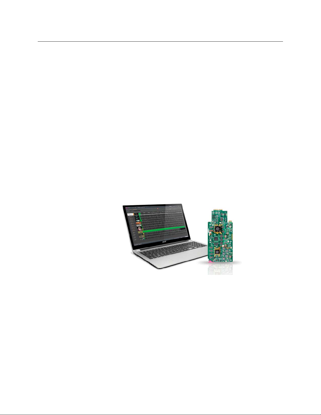
The Densité SSP-3801 is a solid state HD/SD playout server card that is housed in the
Densité 3RU frame. It is essentially a “channel on a card”. The card pulls a copy of the playlist
from the GV STRATUS Playout service, caches the required media from defined media
storage locations, and then plays the media events on air according to the scheduled times
or the manual control commands sent to the GV STRATUS Playout service through the GV
STRATUS Playout web client.
Fig. 1-1: HD/SD Solid-State Playout card (SSP-3801) and GV STRATUS Playout web client
8
Page 9
GV STRATUS Playout
Operator Manual
For more information about the SSP-3801 card, refer to its documentation:
• SSP-3801 Installation and Configuration Guide (M931-9905-110)
• SSP-3801 User Guide (M931-9900-110)
Getting Started
Although the documentation is organized loosely around four typical roles (designated
system administrator, system engineer, transmission operator, and ingest operator), this
may not reflect the practices of your organization. Roles may be defined differently or
assigned to multiple people. The following process is a general description of the steps for
getting started.
The first step is a customer account is created for your organization on Master and Standby
deployments and configured with the necessary security measures. An initial system
administrator user profile is created and login instructions are provided to the person
designated as the point of contact for the role of system administrator. For more
information on the role of designated system administrator, see
designated system administrator, on page 10.
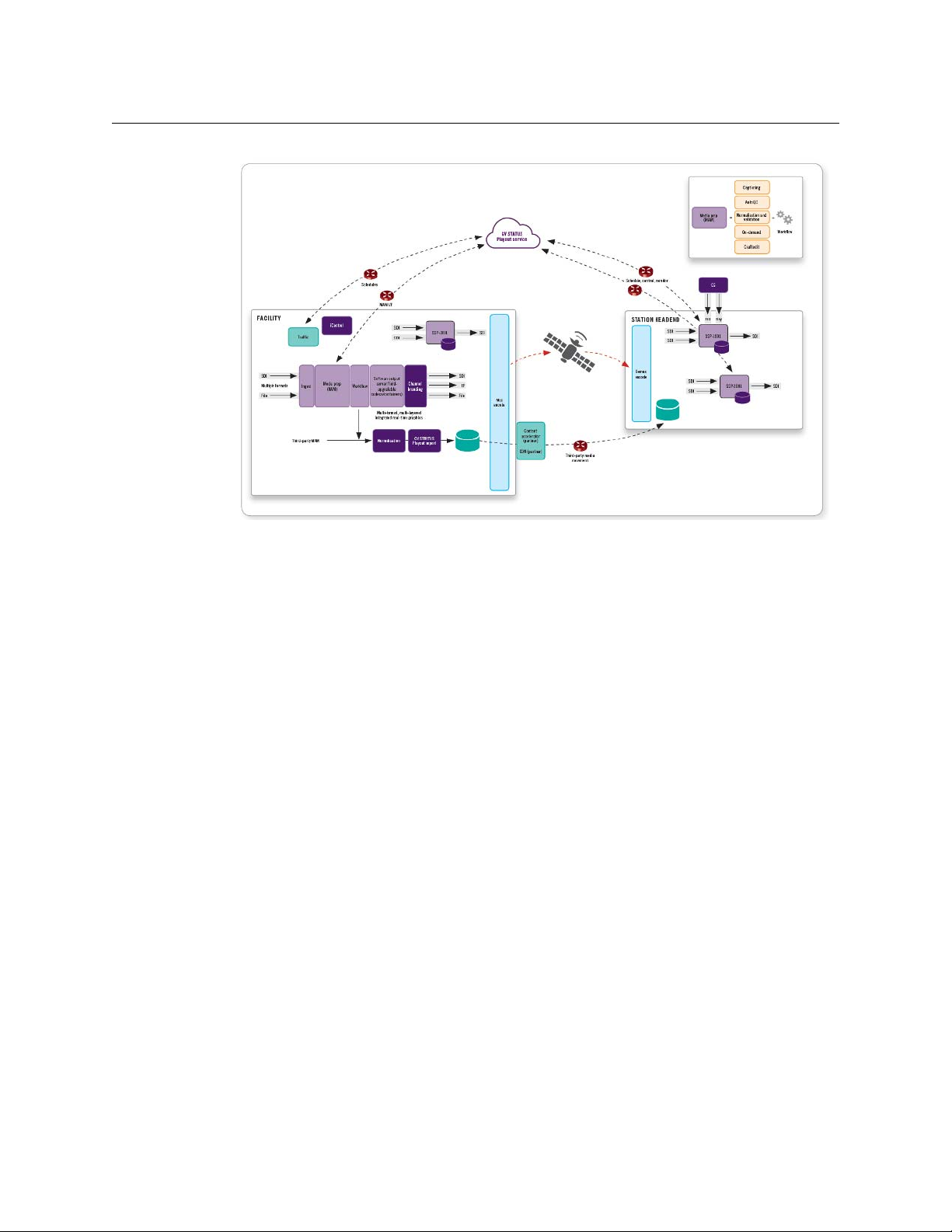
Before going live, you will go through four phases: Installation, Configuration, and
Preparation, Pre-production.
Fig. 1-2: GV STRATUS Playout components
Getting Started as the
Phase 1: Installation and configuration of on-premise components
A system engineer must set up the on-premise components:
1 Install and configure the SSP-3801 cards as required. For more information, see SSP-
3801 Installation and Configuration Guide. To register the cards as devices in your GV
STRATUS Playout account, see
2 Install and configure the traffic system and any other devices as required.
step 6 under Phase 2: Configuration.
9
Page 10

Introduction
Getting Started as the designated system administrator
3 Synchronize the clocks with a time source so the SSP-3801 cards and GV STRATUS
Playout web clients are in sync with each other and with the GV STRATUS Playout
service. For more information, see
and the SSP-3801 cards, on page 18.
Phase 2: Configuration of your GV STRATUS Playout account
The designated system administrator must configure the settings for the account:
1 Define the user groups. The user groups determine what functionality a user is allowed
to view in the interface and use. For more information, see
page 18.
2 Create the user profiles. User profiles are the accounts for individual users. For more
information, see
3 Create the channel types. A channel type is a collection of settings applied as a group
to a number of channels with common characteristics. For more information, see
Creating a new channel type, on page 25.
4 Configure the channels. For more information, see Configuring channels, on page 35.
5 Create views. A view is a collection of channels that are viewed as a group. For more
information, see
6 Register each SSP-3801 card as a device and assign it a channel, see Setting up devices
in GV STRATUS Playout, on page 43.
Configuring user profiles, on page 23.
Grouping channels into a view, on page 41.
Synchronizing time between GV STRATUS Playout
Configuring user groups, on
Phase 3: Preparation of assets and schedules
The designated system administrator or ingest operator must make sure that all the
elements for building a playlist are ready:
1 Prepare the media files for broadcast and register them as assets. For more information,
Registering and Managing Assets, on page 51 and Registering media and
see
importing schedules using the GV STRATUS Playout Gateway, on page 59.
2 Prepare and import the schedules. For more information, see Working with Schedules,
on page 101 and the BXF API specification.
Phase 4: Pre-production
The designated system administrator or system engineer must test the implementation to
ensure that the broadcast will run smoothly:
1 Add schedules to channels. For more information, see Appending a schedule to the
playlist, on page 87.
2 Monitor and control the channels. For more information, see Monitoring and
Controlling the Broadcast, on page 79.
Getting Started as the designated system administrator
When your customer account is created and the initial administrator user profile is created,
one person from your organization must be designated as the system administrator. This
person is responsible for the following:
• Creating user groups to provide the appropriate level of access to the functionality
available in the GV STRATUS Playout service and managing the user groups so they
10
Page 11

continue to meet your organization’s needs. For more information on user groups, see
Configuring user groups, on page 18.
• Creating and managing the user profiles required for the members of your organization
granted access to the GV STRATUS Playout service, and ensuring that they are assigned
to the appropriate user group. For more information on user profiles, see
user profiles, on page 23.
• Configuring the GV STRATUS Playout account and ensuring that the required onpremise components are installed and configured. For more information, see
Installation and configuration of on-premise components, on page 9 and Phase 2:
Configuration of your GV STRATUS Playout account, on page 10.
• Ensuring that all the schedules and assets that are required are available. For more
information, see
• Reporting issues to technical support. Although multiple individuals may be assigned
an Administrator-level user profile, the designated system administrator is sole point of
contact for all communications with technical support.
Registering and Managing Assets, on page 51.
Getting Started as a transmission operator
Once the designated system administrator has configured the settings for the account,
registered the assets, and imported the schedules, the transmission operators can begin
putting channels on air. Transmission operators are responsible for the following:
• Controlling the channel’s playlist. For more information, see Monitoring a channel
using Channel Control, on page 84.
• Monitoring the playout. For more information, see Monitoring channels using the
Monitor Wall, on page 80 and Monitoring channels using the Channel Overview, on
page 80.
• Editing the schedules. For more information, see Working with Schedules, on page 101.
GV STRATUS Playout
Operator Manual
Configuring
Phase 1:
Opening and logging into the GV STRATUS Playout web interface
The designated system administrator creates the user profiles that determine your login
information, the permissions that you have been granted in the service, and what pages
and functionality you will be able to use. The login information you need is the email
address that will serve as your user name and the password associated with that email
address.
Google Chrome is the recommended browser for accessing the GV STRATUS Playout web
client. Once you enter the web address of the GV STRATUS Playout portal provided to you
by the designated system administrator, you will be prompted to provide your login
information.
IMPORTANT
To access the GV STRATUS Playout web interface, a display with a minimum
screen resolution of 1920 x 1080 pixels and the latest version of Google
Chrome at 100% zoom in full-screen (F11) mode is recommended.
The pages and functionality made available to you might differ from that described in the
user documentation since the interface is affected by the permissions granted to your user
11
Page 12
Introduction
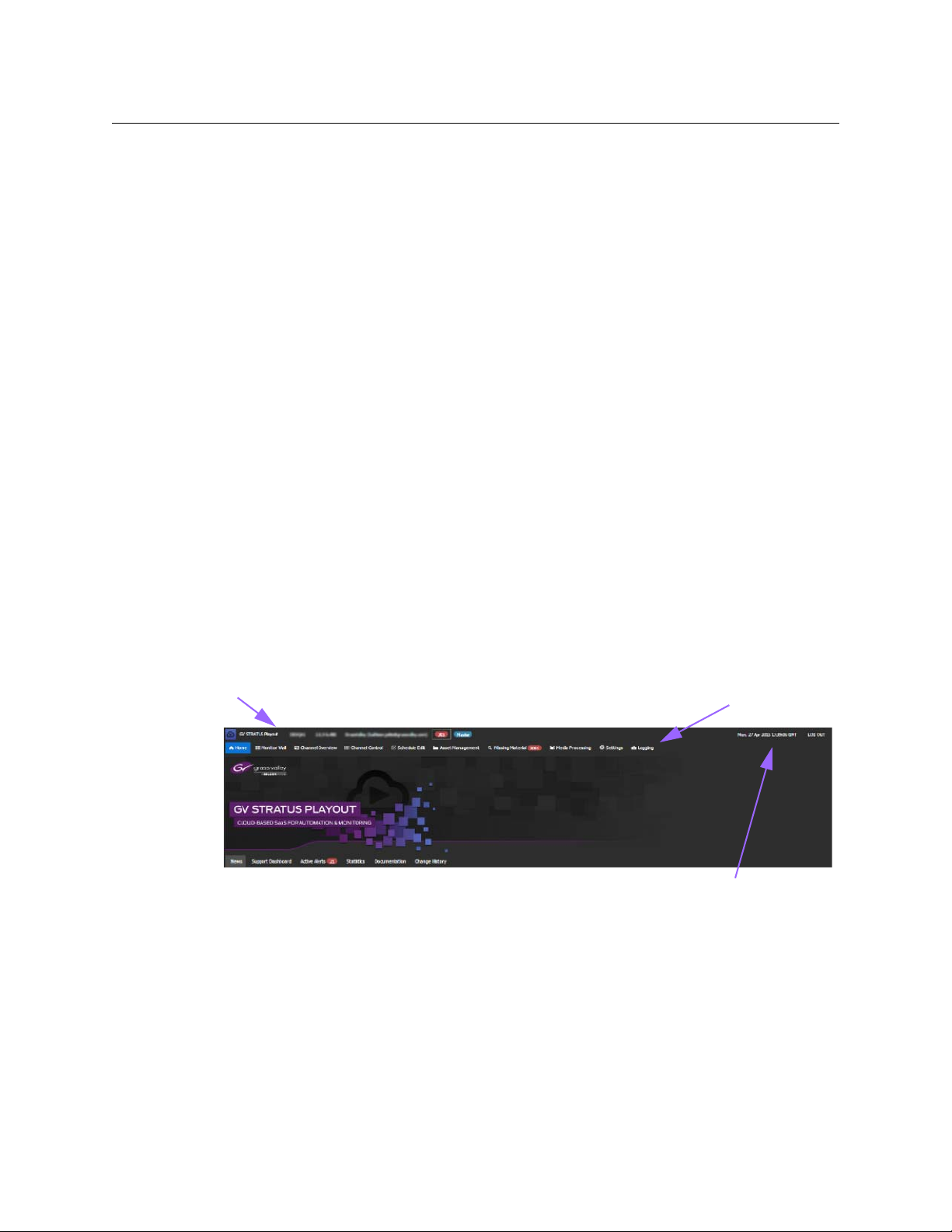
top menu
web client clock
service header
Overview of the web interface
profile through the user group to which you belong. In most cases, the first page you will
see is the Home page. For more information about the pages in GV STRATUS Playout, see
Overview of the web interface, on page 12.
To open the web interface:
1 Open a web browser.
2 In the address bar, type: http://www.cloud.grassvalley.com.
3 Click the name of the deployment provided to you by the designated system
administrator. The checkmarks indicate the location of each deployment.
• To select a master deployment, click the Master tab and click the name of your
• To select a standby deployment (to which the production master fails over to), click
4 If you have more than one GV STRATUS Playout account (email address), then a page
listing your accounts is displayed. Click the one you wish to use to login to the GV
STRATUS Playout service. If you do not have more than one account, skip this step.
5 In the Google sign in page, type the password associated to the account and click Sign
In.
production master.
the Warm Standby tab and click the name of your production warm standby
deployment.
Overview of the web interface
The GV STRATUS Playout cloud services are accessed through the Google Chrome web
browser. Once you have logged in to the service, you can navigate to the various pages
using the top menu.
GV STRATUS Playout always uses UTC time internally. The web client’s internal time is
displayed in the clock in the service header. This clock should always match actual UTC
time. For convenience, however, some pages include the ability to display time using a
different time zone.
Fig. 1-3: Home page
12
Since the service may manage a large number of channels, the designated system
administrator may divide the channels into logical groups, which are referred to as views.
Each view contains a limited number of channels which can be seen as a group on the
Monitor Wall, Channel Overview, and Channel Control pages. A view provides a quick way
Page 13
GV STRATUS Playout
Operator Manual
to see a targeted subset of channels so an operator does not have to repeatedly scroll
through all the channels to locate the ones of interest.
Colored callouts may appear in several areas on the web interface to call your attention to
important information such as notifications and alerts in the service. For example, a callout
will appear on the Missing Materials page to display the number of assets which are
scheduled or calculated to go on air as a primary or secondary event, but whose media files
have not been registered yet.
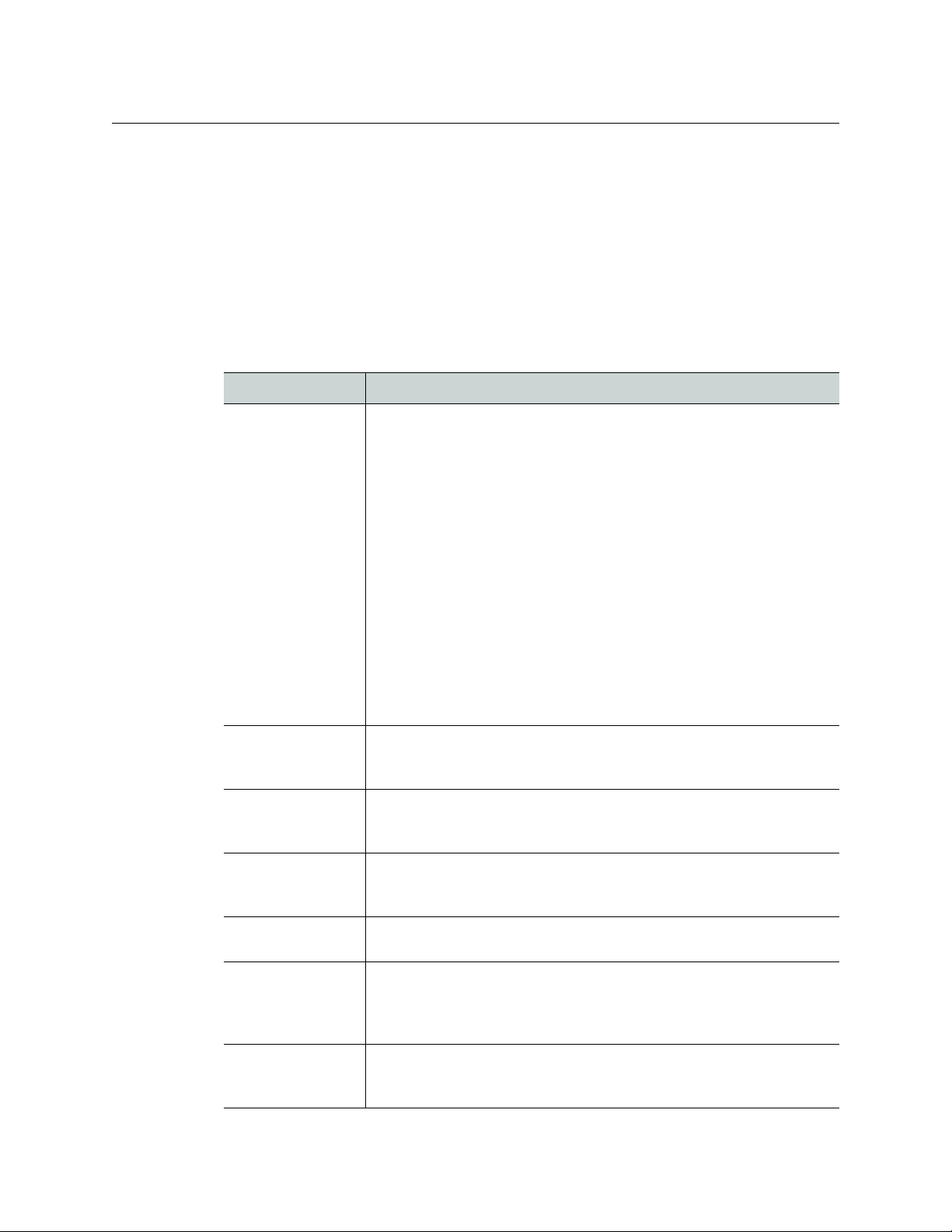
Since the web interface can be customized by the designated system administrator, some
pages or other functionality may be hidden from view. The following describes the main
pages that are available in the top menu by default:
Page Description
Home The Home page contains the following tabs:
• News: provides a message board for designated system administrator
to communicate with all users. For more information, see
News tab, on page 130.
• Support Dashboard: displays the service status, known issues, and
cloud response time for the cloud services. For more information, see
Viewing the status and response time for the service, on page 132.
•Active Alerts: lists the current alerts occurring on the devices in your
account. F
on page 132.
• Statistics: provides performance information for the channels in
your account.
service, on page 133.
• Documentation: contains links to the manuals available for GV
STRATUS Playout and the
Downloading the end user documentation, on page 133.
• Change History: provides a frequently updated list of the changes
made to the services.
changes in the service, on page 134.
Monitor Wall The Monitor Wall is a page from which you can monitor a collection of
up to 17 channels. For more information, see
or more information, see Viewing active alerts in the service,
For more information, see Viewing the statistics for the
SSP-3801 card. For more information, see
For more information, see Reading about
Monitoring channels
About the
using the Monitor Wall, on page 80.
Channel Overview The Channel Overview is a page from which you can monitor the
playout of a collection of channels. For more information, see
Monitoring channels using the Channel Overview, on page 80.
Channel Control The Channel Control page is intended for transmission operators to
control live channels. For more information, see
Monitoring a
channel using Channel Control, on page 84.
Schedule Edit The Schedule Edit page allows operators to create or modify schedules.
For more information, see
Asset Management The Asset Management page provides an interface for searching for
registered assets, editing their details, and previewing the available
proxy media files. For more information, see
page 52.
Missing Material The Missing Material page lists the assets for which the media file is
either missing or has not yet been registered. For more information, see
Reviewing missing material, on page 76.
Working with Schedules, on page 101.
Managing assets, on
13
Page 14
Introduction
GV STRATUS Playout system requirements
Page Description
Media Processing The Media Processing page lists the media files being processed by the
File Processing Nodes. For more information, see
managing media processing jobs, on page 73.
Settings The Settings page contains a menu of tabs containing configurable
settings for the service. For more information, see
account, on page 17.
Logging The Logging page provides a collection of logs and reports. For more
information, see
page 134, Viewing user operations (User Logs), on page 135 and
Viewing transmission error logs (TX Error Logs), on page 136.
Viewing technical logs for the service (System Logs), on
GV STRATUS Playout system requirements
Browser requirements
• The latest version of Google Chrome is recommended and supported.
• Other HTML5-compliant browsers are available and can be used, but are not officially
supported.
• Internet Explorer is currently not supported.
• JavaScript must be enabled.
• Cookies must be enabled.
• Plugins, such as Java, Flash or Silverlight, are not required.
Monitoring and
Configuring your
Client Requirements
Computer:
• A desktop with a wired Internet connection is recommended.
• Laptops, tablets, and other wireless devices may be used, if required. Mobile devices
that support Google Chrome may be used and are subject to the same system
requirements.
• An operating system supported by Google Chrome is required, which currently
includes Windows, Mac OS and Linux. GV STRATUS Playout is browser dependent, but
not platform dependent. For Windows-based systems, minimum recommended
system requirements are Windows 7 with an Intel Core-based processor and 4GB RAM.
Screen:
• A display with a minimum screen resolution of 1920 x 1080 pixels is recommended to
use Chrome at 100% zoom in full-screen (F11) mode. A screen resolution of 1920 x 1200
is recommended for non-full screen mode.
• Smaller resolution screens can be used with Chrome at a reduced zoom.
Clock:
For more information about synchronizing time, see Synchronizing time between GV
STRATUS Playout and the SSP-3801 cards, on page 18.
14
Page 15

GV STRATUS Playout
Operator Manual
• The system clock on the computer from which the GV STRATUS Playout web client is
accessed should be set to synchronize with a time source such as an NTP server or the
station master clock acting as an NTP server.
• If the system clock on the web client’s computer is set to local time, it must be set
correctly using the appropriate time zone settings.
• The SSP-3801 cards and the system clock on the computer from which the GV STRATUS
Playout web client is accessed should also be in sync with each other.
The system clock requirements do not apply to applications or systems
interacting with GV STRATUS Playout through the API such as for systems
running the GV STRATUS Playout Gateway, the
traffic (BXF) systems.
File Processing Node or
15
Page 16

Introduction
GV STRATUS Playout system requirements
16
Page 17

Configuring your account
This chapter contains the following sections:
Synchronizing time between GV STRATUS Playout and the SSP-3801 cards . . . . . . . . . . . . 18
Configuring user groups . . . . . . . . . . . . . . . . . . . . . . . . . . . . . . . . . . . . . . . . . . . . . . . . . . . . . . . . . . . . . . 18
Configuring user profiles . . . . . . . . . . . . . . . . . . . . . . . . . . . . . . . . . . . . . . . . . . . . . . . . . . . . . . . . . . . . . 23
Creating a new channel type . . . . . . . . . . . . . . . . . . . . . . . . . . . . . . . . . . . . . . . . . . . . . . . . . . . . . . . . . 25
Configuring channels . . . . . . . . . . . . . . . . . . . . . . . . . . . . . . . . . . . . . . . . . . . . . . . . . . . . . . . . . . . . . . . . 35
Implementing high availability for channels (channel failover) . . . . . . . . . . . . . . . . . . . . . . . . 39
About off air behavior . . . . . . . . . . . . . . . . . . . . . . . . . . . . . . . . . . . . . . . . . . . . . . . . . . . . . . . . . . . . . . . . 40
Grouping channels into a view . . . . . . . . . . . . . . . . . . . . . . . . . . . . . . . . . . . . . . . . . . . . . . . . . . . . . . . 41
Setting up devices in GV STRATUS Playout . . . . . . . . . . . . . . . . . . . . . . . . . . . . . . . . . . . . . . . . . . . . 43
Opening a device’s web interface . . . . . . . . . . . . . . . . . . . . . . . . . . . . . . . . . . . . . . . . . . . . . . . . . . . . . 47
Configuring the system administration settings . . . . . . . . . . . . . . . . . . . . . . . . . . . . . . . . . . . . . . . 47
17
Page 18

Configuring your account
Synchronizing time between GV STRATUS Playout and the SSP-3801 cards
Synchronizing time between GV STRATUS Playout and the SSP3801 cards
It is important that the time sources for the GV STRATUS Playout web client and the SSP3801 cards are synchronized. If the clocks are not in sync, then some features may not
behave as expected.
SSP-3801 card uses and displays time in UTC. It obtains the date from an NTP server and
time from a choice of time sources. For more information, see SSP-3801 Installation and
Configuration Guide. Its date and time are displayed at the top left of its web interface.
Both the GV STRATUS Playout cloud service and the web clients use UTC internally. Time
management for the cloud service is not required, but each web client relies on the system
clock on the computer from which the web interface is accessed to calculate the UTC date
and time. The date and time calculated by the web client is displayed at the top right of the
web interface beside the Log Out button.
To ensure that the time is accurate, the system clock on the computer should be set to
synchronize with a time source such as an NTP server or the station master clock acting as
an NTP server. The system clock on the computer can be set to UTC or local time. If it is set
to local time, it must be set correctly using the appropriate time zone settings. The time
displayed at the top of both the GV STRATUS Playout and SSP-3801 card web interfaces
should always match actual UTC time.
Since GV STRATUS Playout uses the system clock as a time reference for its functionality, it is
important that the SSP-3801 cards and the system clock on the computer from which the
GV STRATUS Playout web interface is accessed are also in sync with each other. If they are
not, then some features that rely on timing such as Count To and Manual Take Delay may
not give the expected results.
For both the card and the web client’s system clock to be in sync, one of the following must
be implemented:
• If the SSP-3801 cards are not synchronized to a station master clock, then the web
client’s system clock and the SSP-3801 cards should be configured to use the same NTP
server as their time source, if possible.
• If the time source used by the SSP-3801 card can also function as an NTP server, then
the web client system clocks should be configured to use the same time source as the
card.
Although GV STRATUS Playout always uses UTC internally, some pages such as Channel
Control, Schedule Edit, and Asset Management can display time in other timezones
according to the channel type settings. For more information on channel types, see
Configuring channels, on page 35 and Creating a new channel type, on page 25.
Configuring user groups
A user group defines what functionality is available to a group of users. By creating user
groups, you can consistently apply the same settings to a number of user profiles rather
than configuring each of them separately.
18
The service contains two pre-configured user groups:
Page 19
GV STRATUS Playout
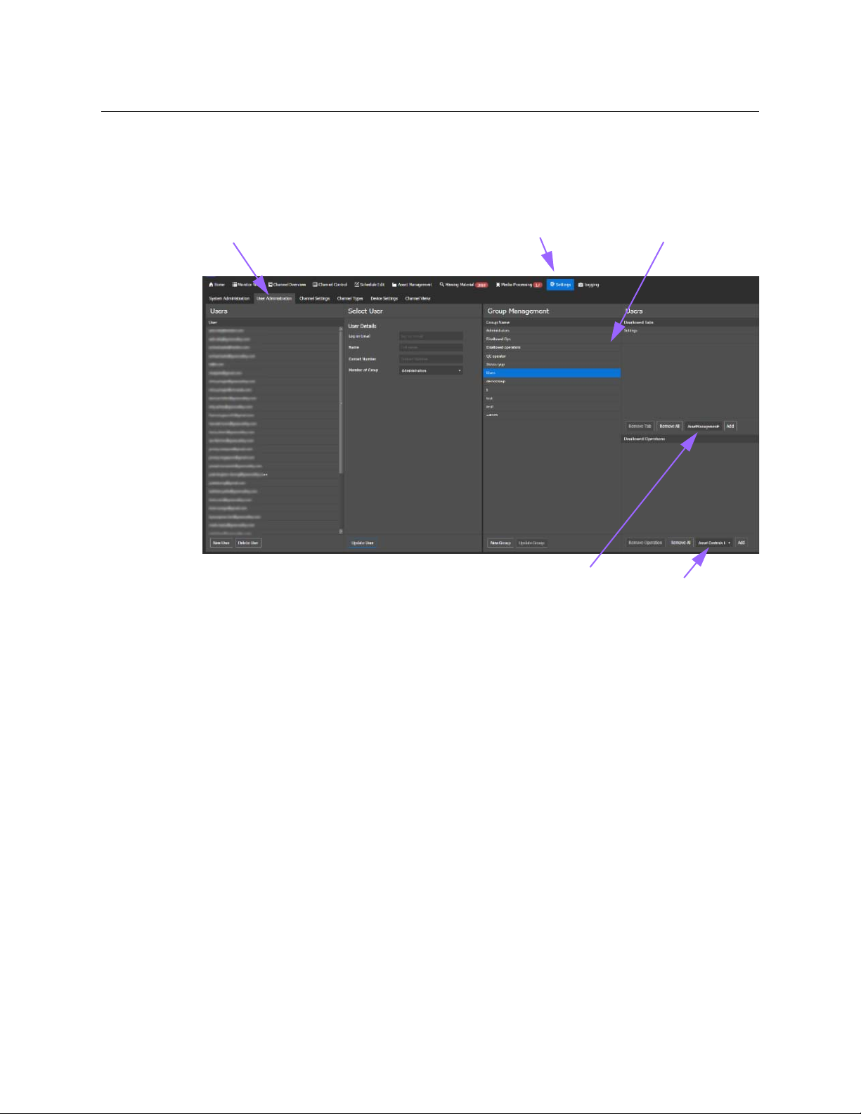
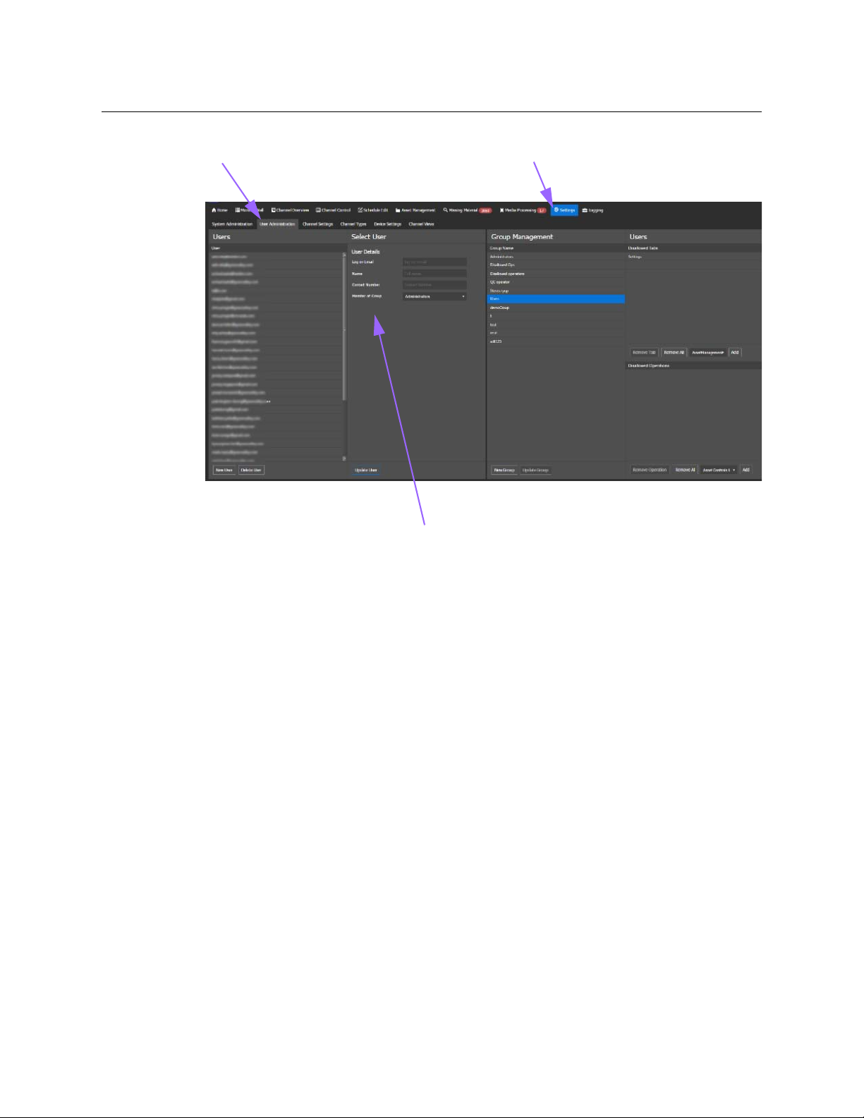
User Administration tab Settings page User groups
Tabs list Operations list
Operator Manual
• Administrators: the Administrators user group is configured with access to all
functionality.
• Users: the Users user group is configured with access to all functionality, except the
Settings page which is only accessible to Administrator-level user profiles.
Fig. 2-1: Example of the User Administration page
User profiles configured as part of the Administrators user group are granted access to all
the available functionality in the account, including making configuration changes on the
tabs available from the Settings page. Although multiple individuals may be assigned an
Administrator-level user profile, the designated system administrator is sole point of
contact for all communications with technical support.
User profiles configured as part of the Users user group are granted access to all
functionality, except the Settings page. The Settings page is restricted to the Administrators
user group only. When you create a new user group, it is based on the functionality
available in the Users user group, but you determine what the users are able to access by
selecting what you want to hide or disable from their view.
The functionality in the account is divided into the pages available in the web interface and
operations (groups of related functionality). To make pages or operations inaccessible from
the user’s view, you select what you want to disallow and add it to one of the Disallowed
panes.
The Tabs list contains the pages and tabs that you can add to the Disallowed Tabs pane. The
pages or tabs that you place in the Disallowed Tabs pane will be hidden from the users of
that user group when they log in to the service.
The Operations list contains the operations that you can add to the Disallowed Operations
pane. The group that you place in the Disallowed Operations pane will result with those
19
Page 20
Configuring your account
Configuring user groups
operations being hidden or disabled from the users of that user group when they log in to
the service.
The Operations list contains the following groups:
Group Functionality included in group
Asset Controls Delete From the Asset Management page:
Asset Controls Edit From the Asset Management page:
Asset Controls Update Status From the Asset Management page:
Channel Control From the Channel Control page:
• Delete Asset
•Save As
• Update Asset
• Status (list is disabled)
• Append Schedule
•Append Events
• Empty Channel
•Cue Next
•Recue
•Take Next
•Hold Next
•Drop Next
Channel Control Backup From Channel Control page:
•Resync
•Failover
Channel Control Edit From the Channel Control page:
•Edit Playlist
Channel Control JIP From Channel Control page:
•JIP
•Cancel JIP
Channel Manual Controls From Manual Controls on the Channel Control page:
•Logo 1 On
•Logo 1 Set/ Unset
•Logo 2 On
•Logo 2 Set/ Unset
•Graphic on
•Graphic Set/Unset
•External Keyer On
•Audio 4 On
•Audio 4 Set/Unset
• Suppress Keyers
• Suppress VANC
Channel Manual Controls
VCHIP
From Manual Controls on the Channel Control page:
•VCHIP On
•VCHIP Set
20
Page 21

GV STRATUS Playout
Operator Manual
Group Functionality included in group
Channel Overview Controls From the Channel Overview page:
• Breakaway Selected
•Return Selected
•Cue Selected
• Take Selected
•Hold Selected
•Drop Next Selected
Live Controls From the Live Controls toolbar on the Channel Control page:
•Return Take
•Return
Live Controls Breakaway From the Live Controls toolbar on the Channel Control page:
• Breakaway-A
• Breakaway-B
Live Controls Breakaway Hold From the Live Controls toolbar on the Channel Control page:
• Breakaway Hold-A
• Breakaway Hold-B
Logging System Logs From the Logging page:
•System Logs tab
Logging TX Error Logs From the Logging page:
•TX Error Logs tab
Logging User Logs From the Logging page:
•User Logs tab
Media Job Delete From the Media Processing page:
• Delete Job
Media Job Edit From the Media Processing page:
•Back to Queue
•Set Priority
21
Page 22
Configuring your account
Creating a user group
Group Functionality included in group
Schedule Controls Delete From the Schedule Edit page:
Schedule Controls Edit From the Schedule Edit page:
• Delete Schedule
• Empty Schedule
• Delete Event
•Edit > Cut
•New Schedule
• Copy Schedule
• Delete Schedule
• Append Schedule
•Append Events
• Add Secondary
• Insert Event
•Append Event
• Edit > Copy, Paste, Drop, Un-Drop, Print List, and Export to
CSV
• Update Event
•Insert
• replacing events using the ID button (ID button is disabled)
Creating a user group
A user group defines what features are available to a group of users. When you create a new
user group, it is based on the functionality available in the Users user group, but you can
restrict that access by selecting which pages or operations are visible and available to the
user profiles assigned to the new user group when they log in to the service. For example,
you can create a user group for transmission operators with monitoring capabilities only by
hiding the Schedule Edit page.
To create a user group:
1 In the top menu, click Settings.
2Click the User Administration tab.
3Click New Group.
4In the Enter group name box, type an identifying name for the group.
5Click Create.
6In the Group Management pane, you configure the user group. Click the name of the
user group you created.
7The Disallowed Tabs pane contains the names of the pages that are hidden from the
user’s view. In the list at the bottom of the Disallowed Tab pane, click the name of a
page that you want to hide and click Add to add a page to the list of hidden pages.
• To remove a page from the list so it is available again, click the page in the
Disallowed Tabs pane and click Remove Tab.
• To clear the list, click Remove All.
8The Disallowed Operations pane contains the names of the groups of operations that
are hidden or disabled from the user’s view. In the list at the bottom of the Disallowed
Operations pane, click the name of the group that you want to disallow and click Add
to add the group to the list of inaccessible operations.
22
Page 23

• To remove a group from the list so its operations are available again, click the name
of the group in the Disallowed Operations pane and click Remove Operation.
• To clear the list, click Remove All.
9Click Update Group.
Modifying the user group
The Disallowed Tabs and Disallowed Operations panes determine what is accessible to the
user profile assigned to the user group. Entries in those panes will result with that
functionality being hidden or disabled from the users of that user group when they log in
to the service.
To modify a user group:
1 In the top menu, click Settings.
2Click the User Administration tab.
3In the Group Management pane, click the name of the user group you want to modify.
4The Disallowed Tabs pane contains the pages that are hidden from the user’s view.
Change as required:
• To add a page to the pane: In the list below the pane, click the name of the page
you want to hide and click Add.
• To remove a page from the pane: In the Disallowed Tabs pane, click the page you
want to remove and click Remove Tab.
• To clear the pane: Click Remove All.
5The Disallowed Operations pane contains the names of the groups of operations that
are hidden or disabled in the user’s view. Change as required:
• To add a group to the pane: In the list below the pane, click the name of the group
you want to disallow and click Add.
• To remove a group from the pane so its operations are available again, click the
name of the group in the Disallowed Operations pane and click Remove
Operation.
• To clear the pane: Click Remove All.
6Click Update Group.
GV STRATUS Playout
Operator Manual
Configuring user profiles
A user profile is a record for a user in GV STRATUS Playout. It contains information such as
the log on email, name, and contact information for the specific user. Each user profile is
assigned to a user group which defines what functionality the user is allowed to view in the
interface and use. The service contains two pre-configured user groups:
• Administrators: the Administrators user group is configured with access to all
functionality.
• Guests: the Guests user group is configured with access to all functionality, except the
Settings page which is only accessible to Administrators.
23
Page 24
Configuring your account
User Administration tab Settings page
User profile
Adding new users
Fig. 2-2: Example of the Settings> User Administration page
Adding new users
New users are identified by the email they use to log in to the GV STRATUS Playout. By
default a new user is assigned to the Guest user group, which restricts their access to many
pages and buttons.
To add a ne w user :
1 In the top menu, click Settings.
2Click the User Administration tab.
3Click New User.
4In the Enter user email address field, type the email address for the user.
5Click Create. The new user is highlighted in the Users list.
6In the User Details section, enter the following:
•In the Name field, type the name of the user.
•In the Contact Number field, type a phone number where the user can be reached.
•In the Member of Group list, click the user group to which you want the user to be
assigned. The Guest group is assigned by default, but it can be changed to any
available user group.
7Click Update User.
24
Page 25

Modifying the user details
To modify the user profile:
1 In the top menu, click Settings.
2Click the User Administration tab.
3In the Users list, click the email address of the profile that you want to update.
4In the User Details section, enter the following:
•In the Name field, type the name of the user.
•In the Contact Number field, type a phone number where the user can be reached.
•In the Member of Group list, click the user group to which you want the user to be
assigned.
5Click Update User.
Deleting a user
To delete a user profile:
1 In the top menu, click Settings.
2Click the User Administration tab.
3In the Users list, click the email address of the profile that you want to delete.
4Click Delete User.
5 In the dialog box, type the code from the left box into the right box to confirm that you
want to delete the user profile. The code changes to green when it is written correctly.
6Click Ye s .
GV STRATUS Playout
Operator Manual
Creating a new channel type
A channel type is a collection of defined settings that can be applied consistently across
multiple channels. For example, you can define a channel type called East Coast which you
can use for all the channels in that region rather than configuring each channel separately.
A channel type can also be used to affect how time is displayed in some pages. Although
GV STRATUS Playout always uses UTC internally, some pages such as Channel Control and
Schedule Edit display time according to their assigned channel type so operators can view
time in the grids in their assigned timezone.
25
Page 26
Configuring your account
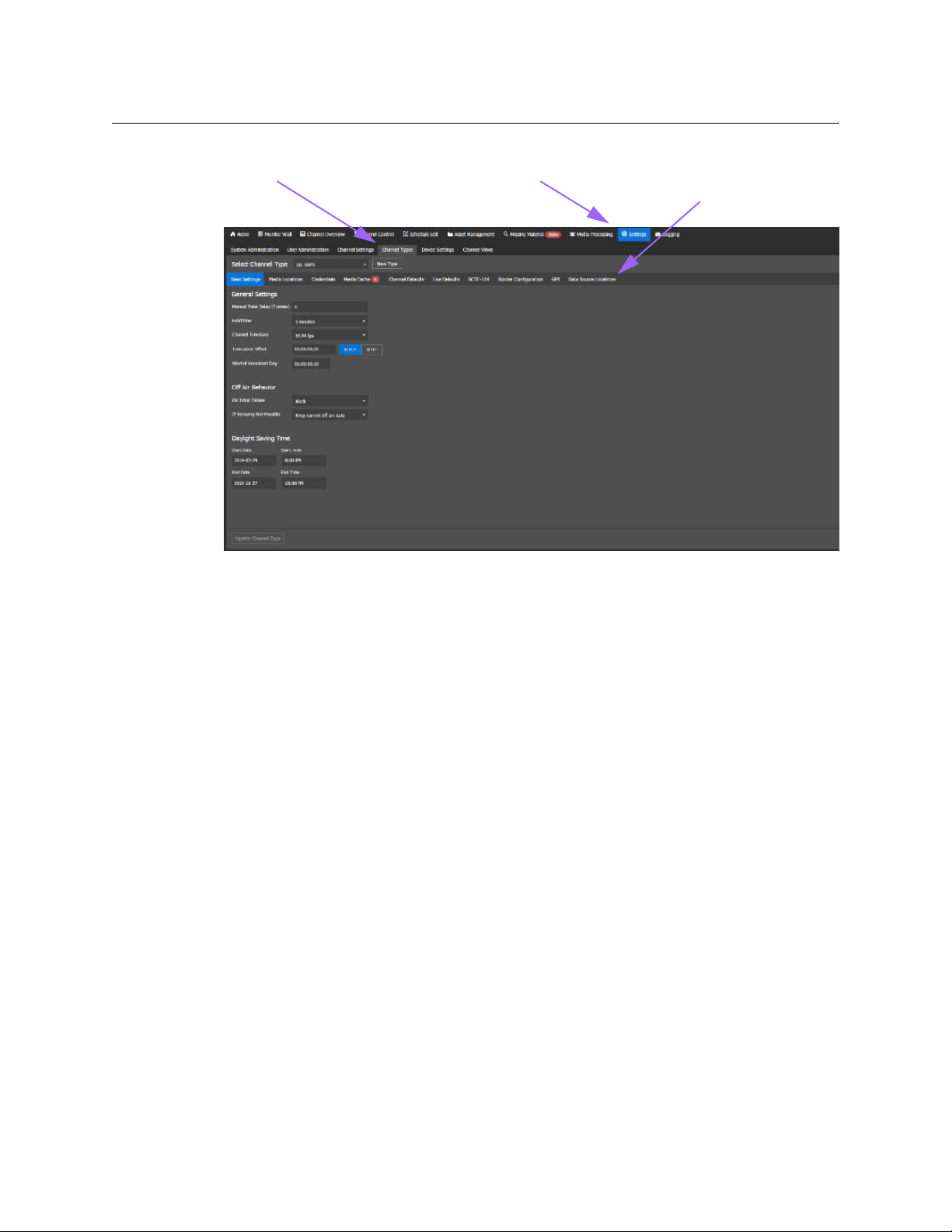
Channel Types tab tabs of settings for
Channel Types
Settings page
Changing the channel type settings
Fig. 2-3: Example of the Settings > Channel Types page
To create a new channel type:
1 In the top menu, click Settings.
2Click the Channel Types tab.
3 Beside the Select Channel Type list, click New Type.
4In the Enter Type Name box, type a name for the new channel type.
5Click Create.
The channel type is created with default values. To change the values, see Changing the
channel type settings, on page 26.
Changing the channel type settings
When you change the settings in an existing channel type, all the channels configured with
the channel type are automatically updated with the new values.
1 In the top menu, click Settings.
2Click the Channel Types tab.
3In the Select Channel Type list, click the name of the channel type you want to change.
4 Click the tab that contains the settings that you want to change:
• Basic Settings: determines the basic settings such as Channel Timebase, Off Air
Behavior and time settings. To configure these settings, continue with
the basic settings for the channel type, on page 27.
• Media Locations: add and order the locations where the media is stored. To list the
media locations, continue with
type, on page 28.
Configuring the media locations for the channel
Configuring
26
Page 27

GV STRATUS Playout
Operator Manual
• Credentials: add the credentials for the locations where the media files and
external data source files are stored, continue with
Configuring the location
credentials for the channel type, on page 29.
• Media Cache: manage the media downloads to the cache. To configure the
settings, continue with
Configuring the media cache for the channel type, on
page 29.
• Channel Defaults: configure the default transitions for logos and graphics and
select the Evergreen content list and media persist list. To configure these defaults,
continue with
Configuring the channel defaults for the channel type, on page 30.
• Live Defaults: configure the transitions for the manually controlled logo, graphic,
voiceover, or breakaway events. To configure these transitions, continue with
Configuring the live defaults for the channel type, on page 31.
• SCTE-104: select how SCTE-104 messages are handled. To configure these settings,
continue with
Configuring the SCTE-104 settings for the channel type, on page 33.
• Router Configuration: specify the router sources available for the source events. To
configure these settings, continue with
Specifying the router sources, on page 33.
• GPI: configure the two General Purpose Input/Output (GPIO) connectors on the
SSP-3801cards. To configure the GPIO, continue with
Configuring the GPIO triggers
for the channel type, on page 34.
• Data Source Locations: add and order the full URLs to where the external data
source files for the Easytext templates are stored. To list the locations, continue
Configuring the locations for the external data source files for the channel
with
type, on page 35. To provide the server credentials, continue with Configuring the
location credentials for the channel type, on page 29.
5 When you have completed your changes, click Update Channel Type.
Configuring the basic settings for the channel type
To configure the basic settings:
1 If you are continuing to configure a selected channel type, skip to step 2. To open the
Channel Settings page:
• In the top menu, click Settings.
•Click the Channel Types tab.
•In the Select Channel Type list, click the name of the channel type you want to
change.
2Click the Basic Settings tab.
3In the Manual Take Delay (Frames) list, select the number of frames of delay it takes for
all the SSP-3801 cards associated to the channel type to receive data from GV STRATUS
Playout. This value is used to ensure changes are applied simultaneously to all the
cards.
4In the Hold time list, click the amount of time an event remains visible in the channel
grid after it has played out. As long as the event appears in the channel grid, it is not
visible in the Show History list of events.
5In the Channel Timebase list, click the frame rate in which the channel operates. The
selected frame rate determines how the timecode is represented in the GV STRATUS
27
Page 28

Configuring your account
Changing the channel type settings
Playout interface. If you change the Channel Timebase, it immediately changes the
frame rate for all the channels (and their devices) configured with this channel type.
6Under Time Zone Offset, specify the time difference between local and UTC time so the
time display for the channel will reflect the local time rather than the UTC time used
internally.
7In the Start of Broadcast Day box, type the time in UTC that marks the beginning of the
broadcast day.
8In the On Initial Failure list, click one of the following actions to occur after the initial
three seconds of an off-air situation has expired and the off-air situation is not resolved
• Black: displays a black screen with no graphics.
• Off Air Slide: displays the full-screen graphic specified in the Off Air Slide field.
• Live A: displays the live feed incoming from the SDI A port on the SSP-3801 card.
• Live B: displays the live feed incoming from the SDI B port on the SSP-3801 card.
9In the Off Air Slide field (if you selected the Off Air Slide option in the On Initial Failure
list), click Select to locate the full-screen graphic to be broadcast if an off-air situation
occurs. The screen graphic used as the off-air slide should be full-screen, in the required
video standard for the channel, and be in OXT format.
10 In the If Recovery Is Not Possible list, select one of the following actions to occur 30
seconds after the On Initial Failure if the off-air situation is not resolved:
• Keep current off air state: continues the action selected in the On Initial Failure list.
• Go to Evergreen: places the Evergreen schedule on-air. For more information
about Evergreen, see
• Take Next: places the next scheduled event on-air.
11 Under Daylight Saving Time, specify the daylight saving time settings for the
configured time zone:
•In the Start Date field, click in the field to open the calendar and select the date
when Daylight Saving Time begins in the time zone. In the Start Time field, click in
the field to open the list of times and select the time when Daylight Saving Time
begins in the time zone.
•In the End Date field, click in the field to open the calendar and select the date
when Daylight Saving Time ends in the time zone. In the End Time field, click in the
field to open the list of times and select the time when Daylight Saving time ends
in the time zone.
12 Continue configuring other settings on the other tabs or click Update Channel Type.
About Evergreen Content, on page 78.
28
Configuring the media locations for the channel type
For the service to access the locations where the folders containing the media files are
stored, you must specify which servers contain the media.
To define the media locations:
1 If you are continuing to configure a selected channel type, skip to step 2. To open the
Channel Settings page:
• In the top menu, click Settings.
•Click the Channel Types tab.
Page 29

GV STRATUS Playout
Operator Manual
•In the Select Channel Type list, click the name of the channel type you want to
change.
2Click the Media Locations tab.
3In the Media Locations section, click Add to add new locations where media files are
stored.
4In the New Media Location dialog box, type the URI for the media location and click
Create. The format of the URI should be http://[URI], https://[URI], or smb://[URI].
5 Define the sequence that the card should follow to download the media. In the Media
Locations section, select the URI and use the arrow buttons to change its position up or
down the list. Order the media locations closest to the card’s location at the top of the
list and the furthest to the bottom. To edit a URI, click the URI, click Edit, and type a new
URI. To delete a URI, click the URI and click Delete.
6 To provide the server credentials for the media locations, continue with Configuring
the location credentials for the channel type, on page 29.
7 Continue configuring other settings on the other tabs or click Update Channel Type.
Configuring the location credentials for the channel type
Since the servers on which the media file folders or external data source files are stored
most likely have security, the service must be configured with the login credentials for
those servers so that the SSP-3801 card can access them.
To define the server login parameters:
1 If you are continuing to configure a selected channel type, skip to step 2. To open the
Channel Settings page:
• In the top menu, click Settings.
•Click the Channel Types tab.
•In the Select Channel Type list, click the name of the channel type you want to
change.
2Click the Credentials tab.
3In the Credentials section, click Add to add the login credentials for the server.
4In the New Credentials dialog box, type the required information in the following fields
to enable access to the server that contains the files and click Save changes:
• URI: type the full URL where the media file folders or external data source files
reside.
• Domain: type the name of the domain.
• Username: type the login name for the specified domain.
• Password: type the password assigned to this username.
To edit a credential, click the credential, click Edit, and enter new information in the
fields. To delete a credential, click the credential and click Delete.
5 Continue configuring other settings on the other tabs or click Update Channel Type.
Configuring the media cache for the channel type
Each channel is associated to a device to which an SSP-3801 card is registered. The SSP3801 card features onboard storage space that allows you to store and preload media
29
Page 30

Configuring your account
Changing the channel type settings
content locally so that it can be retrieved and broadcast smoothly and quickly. You can
define how all the cards associated to the channel type manage their media caches and
what actions they should take if the servers timeout and the media files cannot be
accessed.
Note: Some basic validation is provided on the Media Cache tab to verify if
the values provided fall within the range of acceptable values for the SSP3801 card. A colored callout appears on the tab to call your attention to the
number of validation errors detected on the tab. Each field that contains a
validation error is identified with a warning icon. Hover over the warning
icon to view the range of acceptable values for the field.
To configure the Media Cache settings:
1 If you are continuing to configure a selected channel type, skip to step 2. To open the
Channel Settings page:
• In the top menu, click Settings.
•Click the Channel Types tab.
•In the Select Channel Type list, click the name of the channel type you want to
change.
2Click the Media Cache tab.
3In the Missing Media Time Window box, type the amount of time before broadcast to
trigger the Missing Media alert if the media file cannot be found.
4In the Inaccessible Media Time Window box, type the amount of time before
broadcast to trigger the Inaccessible Media alert if the media file was found, but cannot
be downloaded to the SSP-3801 card’s storage space.
5In the Minimal Download Speed box, type the minimum acceptable download speed
for the media. An alert is triggered if the download speed falls below the specified
threshold.
6In the Speed Test Period box, type the number of seconds defining the length of the
test period used to verify the actual download speed. The download speeds are tested
throughout the specified duration and are averaged. The resulting value is compared
to the Minimal Download Speed threshold to verify its performance.
7In the Max segments per download box, type the maximum number of blocks you can
download per server at a time.
8In the Max (Overall) Parallel Downloads box, type the maximum number of
downloads that can take place simultaneously.
9In the Max SMB Parallel Downloads box, type the maximum number (up to 4) of
downloads that use the Common Internet File System protocol (CIFS) and MS Windows
file sharing protocol (SMB).
10 In the Max HTTP/HTTPS Parallel Downloads box, type the maximum number of
downloads that can take place simultaneously using the HTTP/HTTPS protocol.
11 Continue configuring other settings on the other tabs or click Update Channel Type.
30
Configuring the channel defaults for the channel type
The Channel Defaults tab contains the defaults transition durations for logos and graphics
added to the schedule using the Add Secondary button on the Schedule Edit page.
Page 31

GV STRATUS Playout
Operator Manual
These defaults do not apply to the logos and graphics supplied by BXF. If the transition
durations are not specified by the BXF, then the values default to zero.
To configure the channel defaults:
1 If you are continuing to configure a selected channel type, skip to step 2. To open the
Channel Settings page:
• In the top menu, click Settings.
•Click the Channel Types tab.
•In the Select Channel Type list, click the name of the channel type you want to
change.
2Click the Channel Defaults tab.
3In the In Duration box for Logos, type the total amount of time allocated for the Cut and
Fade transition of the logo on screen to complete.
4In the Out Duration box for Logos, type the total amount of time allocated for the Cut
and Fade transition of the logo off screen to complete.
5In the In Duration box for Graphics, type the total amount of time allocated for the Cut
and Fade transition of the graphic on screen to complete.
6In the Out Duration box for Graphics, type the total amount of time allocated for the Cut
and Fade transition of the graphic off screen to complete.
7In the Evergreen Content List field, click the search button to choose the schedule
containing the Evergreen content. Evergreen content is a library of videos that can be
broadcast in place of a previously scheduled event that for some reason cannot be
played. For more information on Evergreen content, see
About Evergreen Content, on
page 78.
8In the Media Persist List field, click search button to choose a schedule containing a list
of media files that you want to always be available on the SSP-3801 card. The Media
Persist List is normally used for frequently used media files and those needed for the
Manual Controls. The card automatically caches the listed media files, ignoring the
schedule details, so that files are readily available for broadcast and do not need to be
repeatedly cached.
9 Continue configuring other settings on the other tabs or click Update Channel Type.
Configuring the live defaults for the channel type
The Live Defaults determine how a logo, graphic, voiceover, or breakaway event transitions
on or off screen when they are manually controlled using the buttons on the Live Controls
or Manual Controls toolbars on the Channel Control page.
To configure the live defaults:
1 If you are continuing to configure a selected channel type, skip to step 2. To open the
Channel Settings page:
• In the top menu, click Settings.
•Click the Channel Types tab.
•In the Select Channel Type list, click the name of the channel type you want to
change.
2Click the Live Defaults tab.
31
Page 32

Configuring your account
Changing the channel type settings
3Under Breakaway Transition, configure how the Breakaway events (Breakaway-A,
Breakaway-B, Breakaway Hold-A, and Breakaway Hold-B buttons) on the Channel
Control page are handled:
Field Description
Tra nsitio n
Type
Click the type of scene change affect to apply to the beginning of the
breakaway event. When the button is blue, it indicates the feature is
enabled. You have the following choices:
• : it switches from one event to another instantly (Cut)
• : creates a cross-fade between the two events where the incoming
event merges and replaces the outgoing event (Mix)
• : the outgoing event fades to black and the incoming event fades in
(Fade and Fade or V-Fade).
• : the outgoing event switches to black and the incoming event fades
in (Cut and Fade).
• : the outgoing event fades to black and the incoming event appears
instantly (Fade and Cut).
Duration
Type the total amount of time allocated for the transition to complete.
4Under Manual Graphic Transition, configure how the manually controlled graphic
events (Graphic and External Keyer buttons) on Channel Control page are handled:
Field Description
Fade In
Fade Out
Duck
Preset
Opacity
Type the time period over which the graphic appears on screen when
the event is activated.
Type the time period over which the graphic disappears from screen
when the event is deactivated.
Select how much to reduce the level of the background audio (in
decibels).
Select how much to increase the level of the foreground audio (in
decibels).
Select the percentage of opacity between 0% (fully transparent) to 100%
(fully opaque).
5Under Manual Voiceover Transition, configure how the manually controlled voiceover
event (Audio) is handled:
Field Description
Fade In
Type the time period over which the volume of the voiceover event is
raised to 100% when the event is activated.
32
Fade Out
Duck
Preset
Type the time period over which the volume of the voiceover event is
lowered to 0% when the event is deactivated.
Select how much to reduce the level of the background audio (in
decibels).
Select how much to increase the level of the foreground audio (in
decibels).
Page 33

GV STRATUS Playout
Operator Manual
6Under Manual Logo Transition, configure how the manually controlled logo events
(Logo 1 and Logo 2 buttons) are handled:
Field Description
Fade In
Type the time period over which the logo appears on screen when the
event is activated.
Fade Out
Opacity
Type the time period over which logo disappears from screen when the
event is deactivated.
Select the percentage of opacity between 0% (fully transparent) to 100%
(fully opaque).
7 Continue configuring other settings on the other tabs or click Update Channel Type.
Configuring the SCTE-104 settings for the channel type
The SCTE-104 standard allows you to receive trigger messages from the audio or video feed
that flag the start and end points for commercial breaks. It allows you to receive trigger
messages in the SDI (Serial Digital Interface) signal that you can use to control the playlist.
To configure the SCTE-104 settings:
1 If you are continuing to configure a selected channel type, skip to step 2. To open the
Channel Settings page:
• In the top menu, click Settings.
•Click the Channel Types tab.
•In the Select Channel Type list, click the name of the channel type you want to
change.
2Click the SCTE-104 tab.
3 Select the Act upon SCTE-104 splice request triggers check box to execute and log
received SCTE-104 splice messages. Clear the check box to ignore and not log the splice
messages.
4 Select the Block all SCTE-104 messages from being passed-through check box to
prevent all SCTE-104 messages from being sent through the PGM output on the SSP3801 card to other downstream equipment. Clear the checkbox to allow SCTE-104
messages to be sent through the PGM output.
5 Continue configuring other settings on the other tabs or click Update Channel Type.
Specifying the router sources
The Router Configuration tab contains the list of router sources that can be used to
configure the source events. The list of router sources and their mnemonics are obtained
from the devices configured with router systems when their SSP-3801 cards are registered
as a devices with GV STRATUS Playout and the Sync Source Mnemonics button is clicked.
For more information, see
Once you obtain the list of router sources that are available from the device, you can specify
up to 16 router sources which can be chosen when you configure a source event in a
schedule. The router sources are specified by assigning a router source to a box on the
Router Configuration tab.
Configuring the router for source events, on page 46.
33
Page 34

Configuring your account
Changing the channel type settings
To configure the router sources:
1 If you are continuing to configure a selected channel type, skip to step 2. To open the
Channel Settings page:
• In the top menu, click Settings.
•Click the Channel Types tab.
•In the Select Channel Type list, click the name of the channel type you created for
devices connected to a router.
2Click the Router Configuration tab.
3 Assign a router source to each box as required. Each box represents a router source
made available for a source event. To assign the router sources:
• Click the box for the box you want to configure.
•In the Select Device list, click one of the devices that is configured with a router.
• Click the router source you want to assign to the box.
•Click Select.
• Repeat for each router source you want available.
4Click Update Channel Type.
Configuring the GPIO triggers for the channel type
Each SSP-3801 card has two General Purpose Input/Output (GPIO) connectors offering up
to four opto-isolated, open collector GPIOs (see the SSP-3801 User Guide for more
information). The pinouts are 1|G|2 and 3|G|4. The GPIO pins function both as inputs and
outputs. As outputs they can be used to trigger downstream external hardware. As inputs
they can be used to trigger internal pre-programmed actions when they change from one
state to another. It is not recommended to use the GPIO pins as both inputs and outputs
simultaneously.
To configure the GPI triggers:
1 If you are continuing to configure a selected channel type, skip to step 2. To open the
Channel Settings page:
• In the top menu, click Settings.
•Click the Channel Types tab.
•In the Select Channel Type list, click the name of the channel type you want to
change.
2Click the GPI tab.
3In each GPI section, specify the action for each state.
• No Action: a change to the state is not acted upon.
• Take Next: a change to the state triggers a Take Next action, which places the next
event in the playlist on air.
• Cue Next: a change to the state triggers a Cue Next action, which cues the next
primary event, its related secondary events, and any subsequent automatic events
so they are ready to go on air safely when a Take Next action is performed.
• Hold Next: a change to the state triggers a Hold Next action, which prevents the
next events from going on-air.
34
Page 35

GV STRATUS Playout
Operator Manual
• Drop Next: a change to the state triggers a Drop Next action, which removes the
next event in the playlist.
4Click Update Channel Type.
Configuring the locations for the external data source files for the channel type
An Easytext template may contain User data sources that rely on values configured in a file
rather than in the event or in the template itself. This file, called external data source file, is a
simple XML file containing a list of the data source names defined in the Easytext template
and their values, which is validated against the data source schema file. For more
information, see
Once the external data source file is created, it must be hosted on a web, SMB, or FTP server
to allow the SSP-3801card to access the names and values when the Easytext event goes on
air. For the service to access the locations where the external data source files are stored,
you must specify which servers contain the files.
To define the locations:
1 If you are continuing to configure a selected channel type, skip to step 2. To open the
Channel Settings page:
• In the top menu, click Settings.
•Click the Channel Types tab.
•In the Select Channel Type list, click the name of the channel type you want to
change.
2Click the Data Source Locations tab.
3In the Data Source Locations section, click Add to add the full URLs to where data
source files are stored.
4In the New Data Source Location dialog box, type the URI for the external data source
file and click Create. The format of the URI should be http://[URI], https://[URI],
smb://[URI], or ftp://[URI].
5 Define the sequence that the card should follow to download the data source. The card
works in a top down order and downloads the first data source that matches the data
source name provided. In the Data Source Locations section, select the URI and use
the arrow buttons to change its position up or down the list. If two data sources share
the same name but are in different locations (have different URIs), then the order
defines which location is chosen. To edit a URI, click the URI, click Edit, and type a new
URI. To delete a URI, click the URI and click Delete.
6 To provide the server credentials for the external data source locations, continue with
Configuring the location credentials for the channel type, on page 29.
7 Continue configuring other settings on the other tabs or click Update Channel Type.
Preparing an external data source file for an Easytext event, on page 122.
Configuring channels
Instead of configuring channels individually, GV STRATUS Playout uses channel types to
define settings across a number of channels with common characteristics. A channel type
defines settings such as off air behavior, media locations and credentials, and transition
defaults, for example. All the channels configured with the channel type inherit the
35
Page 36

Configuring your account
Channel Settings tab
Settings page
About channel hierarchies
collection of settings from that channel type. Any changes made to the channel type are
then also consistently applied to all the channels in the group. Only the name, location and
assigned device are unique to the channel itself.
GV STRATUS Playout has one pre-configured channel type called Default which is
automatically assigned to new channels. If all your channels use the same settings, then the
Default channel type can be configured to suit those needs. Otherwise, you can create as
many channel types as you require.
About channel hierarchies
36
Fig. 2-4: Example of the Settings > Channel Settings
Channels can be organized into a hierarchical structure so that changes made at the upper
levels are propagated down to their associated channels without losing changes made
locally on those channels. For example, a network channel can determine the playlist for
the day. The playlist consists of several schedules with time slots left for local programming
and commercials. As shown in
associated regional branches which in turn propagate the playlist to their associated city
branches. The regions insert their content into the designated time slots in the schedules
and the changes are propagated to the cities, which in turn insert their own content. Any
changes made to the playlist by channels higher in the hierarchy (parent channels) are
automatically communicated to the lower channels (child channels) and updated on their
devices. Changes are not propagated back up the hierarchy. If a channel is both a parent
and a child like the regional branch in
child channels (city branches) but not up to its parent (network branch).
Figure 2-5, the network propagates the playlist down to its
Figure 2-5, any change is propagated down to its
Page 37

Creating a new channel
Instead of configuring channels individually, GV STRATUS Playout uses channel types to
define settings across a number of channels with common characteristics. When a channel
is created, it is automatically assigned to the channel type called Default. You can change
the channel type when you configure the Channel Details for the new channel. For more
information about channel types, see
GV STRATUS Playout
Operator Manual
Fig. 2-5: Example of a channel hierarchy
Creating a new channel type, on page 25.
To create a new channel:
1 In the top menu, click Settings.
2Click the Channel Settings tab.
3Click New Channel.
4In the Enter Channel Name box, type the name you want to give to the channel.
5Click Create.
6In the Channels list, click the name of the channel that you created.
7In the Channel Details section, complete the basic information for the channel:
•In the Channel Location box, type a label which can be used to identify the
channel location or region, or any other useful label (optional).
•In the Channel Type list, select the channel type that you want to assign to the
channel. The channel type applies a set of defined settings to the channel. For
more information, see
•For Maintenance Mode, click Enable if you want to prevent SSP-3801 alarm
notifications from appearing in GV STRATUS Playout and on-air failures from
appearing in the daily statistics. When the button is blue, Maintenance Mode is
enabled. The alerts are still visible in the card’s web interface.
•In the Auto Fill Schedule section, click Load if you want to choose a schedule from
which approximately 200 events are added to the playlist. If the schedule contains
less than 200 events, the schedule is repeatedly appended to the playlist until it
contains at least 200 events. The Auto Fill Schedule feature is used mostly to
automatically fill the playlist with events to help you perform tests before
launching the channel.
Creating a new channel type, on page 25.
37
Page 38

Configuring your account
Modifying channel details
8Click Update Channel.
9 Assign a device to the channel, as required. For more information, see Setting up
devices in GV STRATUS Playout, on page 43.
Modifying channel details
To update channel details:
1 In the top menu, click Settings.
2Click the Channel Settings tab.
3In the Channels list, click the name of the channel that you want to modify.
4In the Channel Details section, complete the basic information for the channel:
•In the Channel Name box, type a name for the channel.
•In the Channel Location box, type a label which can be used to identify the
channel location or region, or any other useful label (optional).
•In the Channel Type list, select the channel type that you want to assign to the
channel. The channel type applies a set of defined settings to the channel. For
more information, see
•For Maintenance Mode, click Enable if you want to prevent SSP-3801 alarm
notifications from appearing in GV STRATUS Playout and on-air failures from
appearing in the daily statistics. When the button is blue, Maintenance Mode is
enabled. The alerts are still visible in the card’s web interface.
•In the Auto Fill Schedule section, click Load to choose a schedule that will be
repeatedly appended to the playlist or click Clear to remove an existing schedule.
5Click Update Channel.
Creating a new channel type, on page 25.
Creating a channel hierarchy
Channels can be organized into a hierarchical structure so that changes made to the playlist
at the upper levels are propagated down to their associated channels without losing
changes made locally on those channels. For more information on channel hierarchies, see
About channel hierarchies, on page 36.
To create a channel hierarchy, you create a channel and then create channels below it. This
creates a parent-child relationship between the channel (parent) and the channels created
beneath it (children). When you append a schedule to the parent channel, it immediately
propagates the change down to the child channels, therefore inheriting the playlist from
the parent. Changes are not propagated back up the hierarchy so changes on a child
channel do not affect the parent channel. For multiple levels, you create the levels one at a
time from the top level down. Each time you need to create another level, you select a
parent channel and create the children below it.
To create a channel hierarchy:
1 In the top menu, click Settings.
2Click the Channel Settings tab.
3In the Channels list, click the name of the channel that you want to designate as the
top level channel.
4Click New Child Channel.
38
Page 39

GV STRATUS Playout
Operator Manual
5In the Create New Child Channel dialog box, type a name for the channel.
6Click Create.
7In the Channels list, click the name of the child channel you created.
8In the Channel Details section, complete the basic information for the channel:
•In the Channel Location box, type a label which can be used to identify the
channel location or region, or any other useful label (optional).
•In the Channel Type list, select the channel type that you want to assign to the
channel. The channel type applies a set of defined settings to the channel. For
more information, see
•For Maintenance Mode, click Enable if you want to prevent SSP-3801 alarm
notifications from appearing in GV STRATUS Playout and on-air failures from
appearing in the daily statistics. When the button is blue, Maintenance Mode is
enabled. The alerts are still visible in the card’s web interface.
•In the Auto Fill Schedule section, click Load to choose a schedule that will be
repeatedly appended to the playlist or click Clear to remove an existing schedule.
9Click Update Channel.
10 Assign a device to the channel, as required. For more information, see Setting up
devices in GV STRATUS Playout, on page 43.
Creating a new channel type, on page 25.
Implementing high availability for channels (channel failover)
To provide high availability for a channel, you can have two channels set up as a main and
backup pair. Each channel is assigned to a device to support failover between the devices in
case of a card failure or other failover condition on the on air channel.
The channels set up in a main and backup pair are identified by the following:
• The main and backup channels have the same name, but “-Backup” is appended to the
backup channel’s name.
• A small callout appears beside the channel’s name above the channel grid on the
Channel Control page to indicate if the channel is the main or the backup.
For more information on creating a main and backup pair, see Setting up backup channels
for failover, on page 40.
The channel on air is referred to as the active channel. The active channel, whether it is the
main or the backup, is identified on both the Channel Overview and the Channel Control
pages by a green indicator in the first column of the Channels list. If a failover was triggered,
the indicator moves from one to the other; for example, it moves from the main channel to
the backup to show that the backup channel is now the active channel and is on air.
The SSP-3801 cards associated to the devices should be connected to an HCO device, which
provides an automatic method for managing the failover between the devices, or other
system which handles the routing of the playout from the main to the backup. When the
SSP-3801 cards associated to the devices are connected to an HCO device and they are
configured in Auto Failover Mode, then the HCO device will automatically perform the
failover to the backup channel when a failover condition occurs on the active channel. You
can, however, override the HCO device by performing a manual failover. If the SSP-3801
cards associated to the devices are not connected to an HCO device, then the procedure for
39
Page 40

Configuring your account
Setting up backup channels for failover
handling the failover depends on how your system is configured and may require that you
perform the failover manually from the Channel Control page by using the Failover button.
When an HCO device is connected, an HCO button appears beside the channel’s name
above the channel grid on the Channel Control page. The HCO button indicates that an
HCO device is connected to the devices, but it also controls whether or not the HCO is in
Manual or Auto Failover Mode. The HCO device should be in Auto Failover Mode so it can
automatically perform the failover from the main device to the backup when a failure
condition occurs. If it is in Manual Failover Mode, the button appears as “HCO: Manual”. For
more information about configuring an HCO device with the SSP-3801 cards, see the SSP3801 card documentation set.
For more information on performing a manual failover, see Performing a manual failover to
a backup channel, on page 98 and Resynchronizing a backup channel, on page 97.
Setting up backup channels for failover
To provide high availability for a channel, you can create two channels with one serving as
the backup for the other with or without using an HCO device, which can provide an
automatic method for managing the failover between the devices. For more information,
Implementing high availability for channels (channel failover), on page 39.
see
Note: The SSP-3801 card is equipped with a mechanical bypass relay which
sends the SDI IN A signal directly to the SDI Out (PGM) in cases of power loss,
card failure or a manual bypass command. Although some disturbance in the
playout may occur, the bypass relay allows time for the failover to be
performed without a complete loss of signal.
To set up a backup for a channel:
1 In the top menu, click Settings.
2Click the Channel Settings tab.
3 Select the channel which will be designated as the main channel. For more information
on creating channels, see
4Click New Backup Channel. A channel with the same name appended with “-Backup” is
created underneath the main channel.
5 Install and configure a main and backup pair of SSP-3801 cards and also the HCO
device, if required.
6 Register the main SSP-3801 card as device. When you configure the device, select the
name of the main channel in the Assigned Channel list. For more information about
creating a device, see
7 Register the backup SSP-3801 card as device. When you configure the device, select the
name of the backup channel in the Assigned Channel list.
Creating a new channel, on page 37.
Setting up devices in GV STRATUS Playout, on page 43.
About off air behavior
The Off Air Behavior settings define what happens if there is no playlist, you force the
channel off air, or something goes wrong during the broadcast such as a loss of media, an
empty playlist, a missing asset, or a hardware or software crash, for example. The Off Air
Behavior settings are configured in the Basic Settings of the channel type. To configure the
40
Page 41

GV STRATUS Playout
Operator Manual
settings, see Configuring the basic settings for the channel type, on page 27.
When the channel encounters an off-air situation, one of the following occurs:
• If the channel was forced off air and no primary events are available in the playlist, the
configured action in the On Initial Failure list is triggered immediately.
• If no primary event is on air but primary events are available in the playlist, there is a 3
second delay before the configured On Initial Failure action is triggered. During the first
2 seconds of the delay, the last frame of the last played clip remains on air. This allows
time for the channel to resume the playout, if possible. If the channel is unable to
resume playout after 2 seconds, it switches to a black screen for 1 second before
triggering the configured On Initial Failure action.
The On Initial Failure action can be configured to output a black screen, output a live feed,
or output a full-screen slide that announces that the broadcast is off-air. The On Initial
Failure action can activate even in the event of a complete hardware or software crash on
the device assigned to the channel.
If the off-air situation is still not resolved 30 seconds after the On Initial Failure action was
triggered, the action selected in the If Recovery Not Possible list is applied. If a primary
event is pending such as a failed event is being restarted, the card will delay triggering the
If Recovery Not Possible action for up to 30 seconds to allow the possibility of a successful
resumption of the playout.
Grouping channels into a view
A view is a collection of channels that are viewed as a group on the Monitor Wall, Channel
Overview, and Channel Control pages. The configuration for the view determines which
channels are included in the view, which user groups have access to the view, and what
functionality is available on the Monitor Wall, Channel Overview, and Channel Control
pages. The configuration also includes how the timeline is displayed on the Channel
overview page by default and whether or not the secondary events are displayed on the
Channel Overview and Channel Control pages by default.
GV STRATUS Playout provides a default view called All Channels which displays all the
configured channels, but creating separate views provides a quick way to see a targeted
subset of channels. For example, if an operator is monitoring a set of five channels, you can
create a view containing those channels so the operator does not have to repeatedly scroll
through all the channels to locate the ones of interest.
41
Page 42

Configuring your account
Channel Views tab Settings page
Creating a new channel view
Fig. 2-6: Example of the Settings > Channel Views
Creating a new channel view
A view is a collection of channels that are viewed as a group on the Monitor Wall, Channel
Overview, and the Channel Control pages. A view is also configured with a channel
designated as the Primary Channel which is automatically opened in the Channel Control
page when an operator switches to that page after having the view selected in the Monitor
Wall or the Channel Overview. The primary channel is usually the parent channel in a
channel hierarchy, but any channel can be selected according to your preference. For more
information on channel hierarchies, see
Views are assigned to user groups so that only members of those user groups are able to
display the view on the Monitor Wall, Channel Overview, and Channel Control pages.
To cre a te a view :
1 In the top menu, click Settings.
2Click the Channel Views tab.
3Click New View.
4In the Create New View dialog box, type a name for the view.
5Click Create. The new view appears in the Views list.
Configure the view by entering the following information in the right pane.
6In the Basic Settings pane, configure the view:
•In Timeline Height field, type a value to specify the scale of the timeline on the
Channel Overview.
• To display the secondary events in the timeline in the Channel Overview page by
default, click Show Secondaries. When the button is blue, the feature is enabled.
7In the Channels pane, select channels to be included in the view:
About channel hierarchies, on page 36.
42
Page 43

GV STRATUS Playout
Operator Manual
• To select specific channels, click Select Channels. In the Select Channels dialog
box, click the channels you want to include in the view and click Select.
• To remove channels from the list, click the channels that you want to remove and
click Remove Selected.
• To select all the available channels, click Add All.
• To remove all the channels currently in the view, click Remove All.
• To reorder the channels, click the channel that you want to move and click the
arrow buttons to choose the position of the channel in the list. Repeat until the list
is in the desired order.
8In the Primary Channel list, click the name of the channel which is displayed by default
when you open the Channel Control page with this view selected on the Monitor Wall
or Channel Overview.
9In the User Groups pane, select the user groups that will be able to have the view
available on the Monitor Wall, Channel Overview, and the Channel Control pages:
• To select the user groups, click Select User Groups. In the Select User Groups
dialog box, click the user group you want to include and click Select. Repeat for
each user group you want to add to the list.
• To remove a user group from the list, click the user group that you want to remove
and click Remove Selected.
• To select all the available user groups, click Add All.
• To remove all the user group currently in the list, click Remove All.
10 Click Update View.
Deleting a view
To delete a view:
1 In the top menu, click Settings.
2Click the Channel Views tab.
3In the Views list, click the view that you want to delete.
4Click Delete View.
5In the Delete View dialog box, type the code from the left box into the right box to
confirm that you want to delete the view. The code changes to green when it is written
correctly.
6Click Ye s .
Setting up devices in GV STRATUS Playout
When you create a device, you are creating a record for an SSP-3801 card or an application
in GV STRATUS Playout. Once the card or application is registered, it brings the card or
application under management by GV STRATUS Playout. The card or application sends its
status up to GV STRATUS Playout so you can easily monitor its health and be notified to any
alerts which may be occurring.
When you register an SSP-3801 card as a device, the device can then be assigned a specific
channel and begin playout as soon as a schedule is appended to it and the first event is able
43
Page 44

Configuring your account
Device Settings tab Settings page
Creating a device
to play. You can quickly view the system and input alerts listed on the Device Settings page
and launch the card’s web interface directly from the page. The overall health of the device
is also displayed on the Monitor Wall, Channel Overview, and Channel Control pages. You
can also prevent the card from raising alerts in GV STRATUS Playout by placing it
maintenance mode, which will prevent it from raising alerts.
When you register other applications as devices such as the GV STRATUS Playout Gateway
and the File Processing Node, you do not assign the device to a channel. GV STRATUS
Playout simply monitors its status and displays an alert if communication fails with the
application.
When you create a device, the account remains in a pending state until the registration is
completed from the card’s or application’s side. If the registration has not been completed
after 5 minutes, the device account is deleted.
Fig. 2-7: Example of the Settings > Device Settings page
Creating a device
When you create a device, you create a record for an SSP-3801 card or an application in GV
STRATUS Playout. Once the card or application is registered, it brings the card or application
under management.
To create a record for a device:
1 In the top menu, click Settings.
2Click the Device Settings tab.
3Click Register Device.
4In the Enter Device Name box, type a name to identify the device.
44
Page 45

GV STRATUS Playout
Operator Manual
5Click Create. The name of the device that you created should be highlighted in the
Devices list.
6 Copy the key in the Ready to Connect section.
7 Complete the registration through the card’s or application’s interface.
• For the SSP-3801 card, use the card’s web interface to view its System Identity
settings and register the card. For more information, see the SSP-3801 Installation
& Configuration Guide.
• For the File Processing Node, see Converting media using the File Processing Node
application, on page 69.
• For the GV STRATUS Playout Gateway, see Registering media and importing
schedules using the GV STRATUS Playout Gateway, on page 59.
Once the card or application is registered, the Ready to Connect section disappears
from the Device Details pane. The device account remains in a pending state until the
registration is completed from the card’s or application’s side. If the registration has not
been completed after 5 minutes, the account is deleted.
8 If you are registering a SSP-3801 card, the device must be assigned to a channel. In the
Assigned Channel list, click the channel you want to assign to the card.
The device is created with default values. To change the values, see Viewing and
updating device details, on page 45.
Viewing and updating device details
Most of the information listed under Device Details is obtained from the card or application
registered with the device.
To update the device details for a card:
1 In the top menu, click Settings.
2Click the Device Settings tab.
3In the Devices list, click the name of the device that you want to update.
4In the Assigned Channel list, click the channel you want to assign to the SSP-3801 card.
If the device is registered with an application, the channel is not required.
5In the Device Name field, type a name for the device as you want it to appear on the
various pages.
6In the Location box, type a label which can be used to identify the card’s or
application’s location or any other useful label such as the Densité 3 frame ID if the
device is an SSP-3801 card (optional).
7Under Synchronization, the buttons indicate whether the device is synchronized with
GV STRATUS Playout. To synchronize a device that is disabled, click the Enabled button.
When the button is blue, the device is synchronized.
8Click Update Device.
Viewing the status of a device
The SSP-3801 cards feature a comprehensive list of alarms that can raise an alert for the
occurrence of an event, a change of status, or of a specific parameter value. These alarms
can be configured with different alarm levels. When the card is registered as a device, the
45
Page 46

Configuring your account
Configuring the router for source events
state of the alarms is communicated to GV STRATUS Playout. Other devices such as
applications registered as a device are simply monitored and an alert is raised if the device
goes offline.
The Device Status pane contains a list of the available alerts from the device and displays
their current state. The overall health status of the device is determined by whether an alert
is being raised on the device or not and its alarm level. A device is considered ‘Healthy’ if no
alerts are occurring. If an alert is raised, the most urgent alarm state is displayed at the top
of the Device Status pane. To obtain more details about the specific alert raised, you can
click the arrows next to the alarm categories to reveal the lists of specific alerts and their
states.
To view the state of a device:
1 In the top menu, click Settings.
2Click the Device Settings tab.
3In the Devices list, click the name of the device that you want to view.
4 View the information provided in the Device Status pane. Click the arrows in the pane
to reveal the more details.
Configuring the router for source events
A source event is a primary event that streams a live feed from a specified router source
supplied via a router connected to both the SDI A and SDI B inputs on a device’s SSP-3801
card. For source events to function properly:
• Each device intended to playout source events must have an external video router
connected to its associated SSP-3801 card.
• All connected router systems must be of the same type and configured in the same
way.
• The source mnemonics must be same across all the devices.
For more information on configuring the router system, see the SSP-3801 documentation.
To configure the router:
1 Install and configure a router for each SSP-3801 card that you intend to have playout
source events. The configuration of each router system must be the same. For more
information on configuring the SSP-3801 card, see the SSP-3801 documentation set.
2 Create a channel type for all the channels whose devices are connected to a router. For
more information on channel types, see
3 Create a channel for each SSP-3801 card. Configure each channel with the channel type
you created for devices connected to a router. For more information on creating
channels, see
4 Register each SSP-3801 card as a device and assign it one of the channels you created
for devices connected to a router. For more information on registering devices, see
Creating a device, on page 44.
5 Once the device are registered, click Sync Source Mnemonics from one of the devices
connected to a router to obtain the router source mnemonics from the SSP-3801 card.
6 Specify the router sources available for the source events. For more information, see
Specifying the router sources, on page 33.
Creating a new channel, on page 37.
Creating a new channel type, on page 25.
46
Page 47

7 Create a view containing all the channels configured with the channel type you created
System Administration tab Settings page
for devices connected to a router. For more information on creating a view, see
Grouping channels into a view, on page 41.
8 Add source events to a schedule. For more information, see Adding a primary event to
a schedule, on page 103.
Opening a device’s web interface
If the registered device is accessible through a web interface, you can launch its interface
from the Device settings page.
To view the device’s web interface:
1 In the top menu, click Settings.
2Click the Device Settings tab.
3In the Devices list, click the name of the device that you want to view.
4Click Device Web Site.
Configuring the system administration settings
GV STRATUS Playout
Operator Manual
The designated system administrator has full administrative rights the entire system. The
System Administration tab contains the global settings for GV STRATUS Playout.
Fig. 2-8: Example of the Settings > System Administration page
Updating the News tab on the Home page
The News tab on the Home page is used by the Administrators to communicate
information to all the users logging into GV STRATUS Playout. The System News text box in
47
Page 48

Configuring your account
Configuring the Home page banner
which you type the message you want to display is a simple HTML editor so it can include
other items such as images or links to other web pages, for example.
To upd at e t he Ne w s tab:
1 In the top menu, click Settings.
2Click the System Administration tab.
3In the System News section, type the text that you want to appear on the News tab on
the Home page. Use the word processing tools in the toolbars above the text box to
format the text.
4Click Update Details.
Configuring the Home page banner
The banner on the Home page can be customized to display your logo and account name.
Fig. 2-9: Example of a company logo on the Home page
To configure the banner:
1 In the top menu, click Settings.
2Click the System Administration tab.
3In the Account Full Name box, type the name of the site as you want it to appear on the
Home page.
4In the Upload Company Logo box, click Choose File and select the image file that you
want to have appear on the Home page. The image should be a maximum of 163 pixels
in height and be in the PNG format.
5Click Update Details.
Configuring the default date format
You can choose how the date is displayed on the Channel Control and the Schedule Edit
pages by selecting a format from the list available in the Display Date Format field on the
Settings > System Administration page.
To configure the date format:
1 In the top menu, click Settings.
2Click the System Administration tab.
3In the Display Date Format field, click the format you want to use to display the date on
the Channel Control and Schedule Edit pages.
4Click Update Details.
48
Page 49

Configuring the default time zone offset for the channel types
Although GV STRATUS Playout always uses UTC internally, some pages such as Channel
Control and Schedule Edit display time according to their assigned channel type. The
channel type contains a Time Zone Offset setting which specifies the time difference
between the local and UTC time so operators can display time in the grids in their time zone
rather than the UTC time used internally. For more information on channel types, see
Creating a new channel type, on page 25.
The default value for the Time Zone Offset is configured on the Settings > System
Administration page. Once the default is configured, each new channel type created is
configured with the specified value.
To configure the default time zone offset:
1 In the top menu, click Settings.
2Click the System Administration tab.
3In the Default Time Zone Offset field, type the time value that specifies the time
difference between the local and UTC time used by default.
4Click Update Details.
GV STRATUS Playout
Operator Manual
Configuring the contact details for the designated system administrator
To configure the designated system administrator’s contact details:
1 In the top menu, click Settings.
2Click the System Administration tab.
3In System Administrator section, configure the following:
•In the Name box, type the name of the person designated as the point of contact
for system administration issues.
•In the Email box, type the email address used to communicate system
administration issues.
•In the Contact Phone Number box, type the telephone or cellphone number
where the designated system administrator can be reached.
4Click Update Details.
Configuring the default status for assets
Assets registered with GV STRATUS Playout are labeled with a status which defines their
readiness to go on air. If you have a quality control workflow for the media files after they
are registered as assets with GV STRATUS Playout, you can use the status descriptions to
identify which assets are not in an acceptable or approved state.
An asset can be labeled with one of the following status descriptions:
• New: indicates that the asset has not been verified.
• Action Required: indicates that the asset has been verified, but issues with it have been
discovered and remain unresolved.
• Ready To Air: indicates that the asset has been verified and has been deemed
acceptable to go on air.
49
Page 50

Configuring your account
Configuring the default status for assets
As the asset progresses through your quality control workflow, its status can be changed
accordingly on the Asset Management page. When an asset is defined with a Ready To Air
status, the Asset Details on the Asset Management page can no longer be edited. To make
changes to the asset, a user must change the status to Action Required or New so edits can
be performed.
If you want to limit who has the authority to change the status of an asset, you can create a
user group which grants permission to change the status of the asset and disallow that
functionality from other user groups (see the Operation Group called Asset Controls
Update Status in
If an asset is defined with a status of New or Action Required when it appears in a schedule,
a warning is triggered and visible on the Channel Control and Schedule Edit pages. The
warning will not prevent the event from going on air.
As assets are registered with GV STRATUS Playout, they are assigned a default status. If you
do not have a quality control workflow for the media files after they are registered as assets
with GV STRATUS Playout, the recommended default status is Ready To Air. Choosing it as a
default status will prevent the unnecessary triggering of the warning on the Channel
Control and Schedule Edit pages. Each time an update to an asset occurs such as through a
traffic system or GV STRATUS Playout Gateway, the status will automatically revert to the
default status configured for the account.
Configuring user groups, on page 18).
To configure the default status for newly registered assets:
1 In the top menu, click Settings.
2Click the System Administration tab.
3In the Default Asset Status list under Account Options, select one of the following:
• New: indicates that the asset has not been verified.
• Action Required: indicates that the asset has been verified, but issues with it have
been discovered and remain unresolved.
• Ready To Air: indicates that the asset has been verified and has been deemed
acceptable to go on air.
4Click Update Details.
50
Page 51

Registering and Managing Assets
This chapter contains the following sections:
Managing assets . . . . . . . . . . . . . . . . . . . . . . . . . . . . . . . . . . . . . . . . . . . . . . . . . . . . . . . . . . . . . . . . . . . . . 52
Registering media and importing schedules using the GV STRATUS Playout Gateway . . 59
Exporting the As Run logs using the GV STRATUS Playout Gateway . . . . . . . . . . . . . . . . . . . . 68
Converting media using the File Processing Node application . . . . . . . . . . . . . . . . . . . . . . . . . 69
Monitoring and managing media processing jobs . . . . . . . . . . . . . . . . . . . . . . . . . . . . . . . . . . . . 73
Reviewing missing material . . . . . . . . . . . . . . . . . . . . . . . . . . . . . . . . . . . . . . . . . . . . . . . . . . . . . . . . . . 76
About Evergreen Content . . . . . . . . . . . . . . . . . . . . . . . . . . . . . . . . . . . . . . . . . . . . . . . . . . . . . . . . . . . . . 78
51
Page 52

Registering and Managing Assets
Asset Management page
searchable list of assets MP4 proxy media
preview pane
information contained
as part of the asset
Asset
Usage
Managing assets
Managing assets
Media files are not stored directly in the cloud as part of the GV STRATUS Playout service.
Rather than importing or uploading physical files into the service, the media files are stored
on premise and are registered as assets with the service using the GV STRATUS Playout
Gateway. An asset is a record for one media file containing its name (house number), title,
the locations where it is available for download, and other editable properties. If a media
file is registered from multiple locations, the asset is automatically updated with the URLs
for each location. For more information on the GV STRATUS Playout Gateway, see
Registering media and importing schedules using the GV STRATUS Playout Gateway, on
page 59.
The Asset Management page provides an interface from which you can search for assets,
view and edit the properties provided for the asset, preview its proxy media file (if available)
and view in which schedules the asset appears.
Fig. 3-1: Example of the Asset Management page
Editing an asset
An asset is a record containing information about a media file in the GV STRATUS Playout
service. The asset contains a unique identification number (GUID), the name (or house
number) for the media file, its title, the URLs for all the locations where it can be found, and
properties such as its frame rate.
The GV STRATUS Playout Gateway will automatically create the asset when it registers the
media file with the service. When a media file is registered, the file name minus the
52
Page 53

GV STRATUS Playout
Operator Manual
extension is compared to the asset names. If the file name matches the name of an existing
asset, then the URL for its storage location is added to the existing asset. For example, if you
register a media file called HN000123.mxf, it will search for an asset with the name
“HN000123”. If it finds an asset of that name, then the URL of the newly registered media file
is added to the asset. For more information on the GV STRATUS Playout Gateway, see
Registering media and importing schedules using the GV STRATUS Playout Gateway, on
page 59.
When you edit the properties of an asset in the Asset Management page, the changes are
only stored in the asset and do not get saved back to the media file.
To edit an asset:
1 In the top menu, click Asset Management.
2 In the left pane, locate and click the asset that you want to modify. For more
information on using the search fields, see
Searching for assets, on page 57.
3In the Asset Details section, change the properties as desired:
Option Description
GUID
Name
Title
Global ID
Status
Content Type
Keywords
Asset URL(s)
Displays the unique identification number (GUID) for the asset.
Type the name (or house number) of the asset. Make sure that the name
matches the file name of the media file to be registered.
Type the descriptive title for the asset.
Type the Global ID for the asset such as an Ad-ID or an Industry
Standardized Commercial Identifier (ISCI) code.
Select the readiness of the asset. The status of the asset will not prevent
the event from going on air. Click one of the following:
• New: indicates that the asset has not been verified.
• Action Required: indicates that the asset has been verified, but issues
with it have been discovered and remain unresolved.
• Ready To Air: indicates that the asset has been verified and has been
deemed acceptable to go on air.
When an asset is defined with a Ready To Air status, the Asset Details on
the Asset Management page cannot be edited. To make changes to the
asset, a user granted the necessary permissions
(see Configuring user
groups, on page 18) can change the status to Action Required so edits
can be performed.
Type a label for the asset such as commercial or promo, for example.
Type a list of keywords separated by a vertical bar ( | ). Keywords facilitate
searching for the asset when you use the Search Any field.
Displays the URLs for all the locations where the media file can be found.
Proxy URL
Displays the URL for all the location where the MP4 proxy media file can
be found.
53
Page 54

Registering and Managing Assets
Editing an asset
Option Description
Asset Viewer
Timebase
Start of Media
End of Media
If the asset contains a MP4 proxy media file and it is accessible, the proxy
file will be shown in the preview pane in the
the proxy is available, you can do the following:
• To view the proxy media file, click the Play icon. Click in the MP4 proxy
media preview pane to start or stop the playback.
• To jump to a specific timecode, type a timecode relative to the clip start
timecode in the timecode field or click in the slider.
• To move frame by frame through the proxy media file, click the arrow
buttons on either side of the timecode field.
• To set the In Point marker, scroll to the first frame of the video that
should be seen on screen and click
the In Point field. To set the Out Point marker, scroll to the last frame of
the video that should be displayed on screen and click
transfer the timecode to the
• To skip to the existing markers, click Cue To In to jump to the In Point
marker and click
Click the frame rate for the asset.
Displays the timecode for the fist frame of the media. If no timecode was
provided when the asset was registered such as when registering BXF or
iTX Asset XML files, then the field defaults to 00:00:00;00.
The Start of Media (SOM) is the first frame of the media and the clip start
timecode is the timecode label associated with that first frame. The clip
start timecode may not necessarily start at 00:00:00;00 since many clips
may have an offset start timecode; for example, when a show is split into
multiple one-hour segments, the second segment may have a clip start
timecode of 01:00:00;00.
Note: Incorrect drop-frame timecodes are automatically rounded up to
the next valid drop-frame timecode value; for example, 00:01:00;00
would be rounded up to 00:01:00;02.
Displays the timecode for the last frame of the media. If no timecode was
provided when the asset was registered such as when registering BXF or
iTX Asset XML files, then the field defaults to 00:00:00;00.
The End of Media (EOM) is the last frame of video in the media relative to
the clip start timecode.
Note: Incorrect drop-frame timecodes are automatically rounded up to
the next valid drop-frame timecode value; for example, 00:01:00;00
would be rounded up to 00:01:00;02.
Cue To Out to jump to the Out Point marker.
Mark In to transfer the timecode to
Out Point field.
Asset Preview tab. When
Mark Out to
54
Page 55

Option Description
GV STRATUS Playout
Operator Manual
In Point
Out Point
Duration
Type the timecode for the first frame of the video that should be seen on
screen relative to the clip start timecode.
Often the In Point timecode is the same as the Start of Media (SOM);
however, some media files may contain unwanted content at the start of
the file that should not be displayed. In those cases an In Point timecode
can be used to specify that playout should start after that unwanted
content. If the In Point and Out Point timecodes are both 00:00:00, the
entire media file plays.
If the SOM was provided when the asset was registered, the timecode
entered as the In Point is validated against the SOM timecode to ensure
that it is within the valid range of the media. When an invalid timecode is
entered, the field is highlighted in red and you will not be able to save
the changes to the asset. If the SOM was not registered, no validation is
performed.
Note: Incorrect drop-frame timecodes are automatically rounded up to
the next valid drop-frame timecode value; for example, 00:01:00;00
would be rounded up to 00:01:00;02.
Type the timecode for the last frame of the video that should be
displayed on screen relative to the clip start timecode.
Often the Out Point and End of Media (EOM) are the same; however, if
the media ends with content that should not be displayed such as black,
a Out Point timecode can be set to ensure the clip ends before the
unwanted content is displayed. If the In Point and Out Point timecodes
are both 00:00:00, the entire media file plays.
If the EOM was provided when the asset was registered, the timecode
entered as the Out Point is validated against the EOM timecode to
ensure that it is within the valid range of the media. When an invalid
timecode is entered, the field is highlighted in red and you will not be
able to save the changes to the asset. If the EOM was not registered, no
validation is performed.
Note: Incorrect drop-frame timecodes are automatically rounded up to
the next valid drop-frame timecode value; for example, 00:01:00;00
would be rounded up to 00:01:00;02.
Type the total amount of time allocated for the asset to play.
Note: Incorrect drop-frame timecodes are automatically rounded up to
the next valid drop-frame timecode value; for example, 00:01:00;00
would be rounded up to 00:01:00;02.
4Click Update Asset to save the changes to the asset or click Save As to save a copy of
the asset under a different name.
Viewing in which schedule the asset appears
The Asset Usage pane on the Asset Management page displays all the schedules that
contain the asset and the time it is scheduled to play.
55
Page 56

Registering and Managing Assets
Channel Type list
Viewing the list of data sources contained in an Easytext template
Fig. 3-2: Asset Usage on the Asset Management page
To view the schedules containing a selected asset:
1 In the top menu, click Asset Management.
2 In the left pane, locate and click the asset. For more information on using the search
fields, see
3 View the list of schedules containing the asset in the Asset Usage pane.
4 The time in the Time column is displayed according to the selected channel type. To
change the channel type, select the desired channel type from the Channel Type list.
Searching for assets, on page 57.
Note: To filter the Time column, use the format YYYY-MM-DD HH:MM:SS.
Viewing the list of data sources contained in an Easytext template
The Easytext section on the Asset Management page displays all the User data sources
configured in the Easytext template that rely on values set in the event. It only appears
under Asset Details when the Easytext media type is selected.
56
Page 57

GV STRATUS Playout
Easytext media type list of User data sources
from Easytext template
Operator Manual
Fig. 3-3: Asset Usage on the Asset Management page
To view the schedules containing a selected asset:
1 In the top menu, click Asset Management.
2 In the left pane, locate and click the asset. For more information on using the search
fields, see
3Click the Data Sources arrow to display the list of User data sources contained in the
Easytext template that rely on values configured in the event.
Searching for assets
You can search for assets by using a combination of search features available on the Asset
Management page.
Searching for assets, on page 57.
57
Page 58

Registering and Managing Assets
Type of media
Search by keyword
Filter by first letter
Advanced filtering
Advanced filtering icon
Deleting an asset
Deleting an asset
Fig. 3-4: Searching for assets on the Asset Management page
To view assets:
1 In the top menu, click Asset Management.
2 Click the type of media that you want to search.
3 Do one of the following:
• To search using keywords, type a keyword in the Search Any field.
• To filter the list according to the first character of the asset name, type the
character in the Begins With field.
• To view the entire list, click in either search fields and press Backspace.
4 To further filter the list in a column, click the advanced filtering icon, select the type of
filter you want to use, and type the characters to be used with the selected filter in the
field beside the icon.
When you delete an asset from the Asset Management page, it removes the record of the
media file from GV STRATUS Playout service, including the unique identification number
and name for the media file and the URLs for all the locations where it can be found. When
the asset record is deleted, the GV STRATUS Playout service sends a request to an online GV
STRATUS Playout Gateway to perform the deletion of the media file. The GV STRATUS
Playout Gateway that responds to the request will perform the deletion of the media file if
its Allow Media Deletes checkbox is selected and the URL listed in the asset’s Media
Locations field matches the URI entered in the GV STRATUS Playout Gateway’s Inbox Uri
field. If they match, then the URL is converted to an SMB address and the GV STRATUS
Playout Gateway deletes the media file in that location.
58
Page 59

GV STRATUS Playout
Operator Manual
To delete an asset:
1 In the top menu, click Asset Management.
2 In the left pane, click the name of the asset that you want to delete.
3Click Delete Asset.
4 In the dialog box, type the code from the left box into the right box to confirm that you
want to delete the asset. The code changes to green when it is written correctly.
5Click Ye s .
Registering media and importing schedules using the GV STRATUS Playout Gateway
GV STRATUS Playout Gateway is an application used to register media files as assets and
import schedules. It monitors a designated watch folder for new files and then
automatically performs the operations as required by the type of file and the application’s
configuration to enter the data into the GV STRATUS Playout service.
Fig. 3-5: GV STRATUS Playout Gateway
Media files
When a new file is placed in the watch folder, it is automatically registered in the GV
STRATUS Playout service as an asset. It is recommended that you organize your media files
and Easytext templates in the watch folder in a hierarchy of folders with meaningful names.
When the files are registered, the folder names are converted into keywords associated to
the files and stored as metadata with the asset. These keywords facilitate the search for files
in the Asset Management page and in the file selection dialog boxes.
To be compatible with the SSP-3801 card, verify the supported formats for media files in the
SSP-3801 User Guide. If your media files are not in a compatible format, you can convert the
media files to a supported format using the Media Conversion Processor job that you can
59
Page 60

Registering and Managing Assets
Installing the GV STRATUS Playout Gateway
add when you configure the watch folder (see Configuring the watch folder, on page 62) or
you can use the File Processing Node application (see Converting media using the File
Processing Node application, on page 69).
iTX Asset XML
GV STRATUS Playout Gateway includes limited support for importing asset metadata via
the import version of the iTX Asset XML schema. When an Asset XML file is placed in the
watch folder, the asset metadata is imported and registered as an asset in the GV STRATUS
Playout service. For more information on import Asset XML, please refer to the iTX
documentation set.
The following Asset XML fields are supported:
• AssetType (only Video, Audio, Graphic, and Logo types are supported)
•Name
•Title
• FrameRate (all are supported)
• InPoint (TimeFormat can be Frames, Miliseconds, Ticks, or Timecode)
• Duration (TimeFormat can be Frames, Miliseconds, Ticks, or Timecode)
• Uid (stored as an external reference in the registered asset)
• MediaLocations: LocationType (only iTX and Proxy are supported) and MediaPaths
iTX XML schedules
GV STRATUS Playout Gateway also supports iTX XML schedules. When an iTXML schedule
(.xml or .itxml) is placed in the watch folder, it is automatically imported, converted into a
GV STRATUS Playout schedule, and named according to the schedule name in the iTXML
file (not the file name itself). If a schedule with the same name already exists, the existing
schedule is overwritten with the imported schedule. For more information on iTX XML
schedules, please refer to the iTX documentation set.
The following iTX event types are supported:
• TXMediaEvent: converts to a Clip primary event
• TXLiveEvent: converts to a Live primary event supplied via the SDI A port on the
associated device
• TXCommentEvent: converts to a Comment event
• TXAudioEvent: converts to an Audio Clip secondary event
• TXGraphicEvent: converts to a Graphic secondary event
• TXLogoEvent: converts to a Logo secondary event
• TXVANCEvent: converts to a VANC secondary event
Installing the GV STRATUS Playout Gateway
The GV STRATUS Playout Gateway can be installed on any computer in the network. Once
installed, it must be registered as a device in GV STRATUS Playout. The GV STRATUS Playout
Gateway instance is monitored by the GV STRATUS Playout service and will raise an alert if it
goes offline.
60
Page 61

GV STRATUS Playout
Settings pageSystem Administration tab
Download the GV STRATUS Playout Gateway
Operator Manual
You can install and register GV STRATUS Playout Gateway instances on different computers
in your network to monitor multiple watch folders. You may want to set up watch folders on
multiple computers to support multiple instances of the File Processing Node application
or to import the same media files from different locations. To monitor multiple watch
folders, repeat the process for each location. In each location install a GV STRATUS Playout
Gateway instance, designate a watch folder, and configure the GV STRATUS Playout
Gateway instance to monitor the designated folder.
To install the GV STRATUS Playout Gateway:
1 In the top menu, click Settings.
2Click the System Administration tab.
3Under Software Downloads, click the Gateway button.
Fig. 3-6: Example of the System Administration page for downloading GV STRATUS Playout Gateway
4 If you do not have the listed prerequisite software installed, click Install and then install
the application. Otherwise, click launch to open the GV STRATUS Playout Gateway.
5 Before you can proceed, you must register the GV STRATUS Playout Gateway as a
device in GV STRATUS Playout, but you do not need to assign it to a channel. For more
information, see
Creating a device, on page 44. Copy the key provided for the device.
6 Once you have created the device in GV STRATUS Playout, you need to provide the key
to the GV STRATUS Playout Gateway so it can register itself with the device that you
created. To complete the registration, provide the required information in the Enter
registration code dialog box:
•In the Deployment list, click the name of the deployment to which you are
registering the GV STRATUS Playout Gateway.
•In the Code field, paste or type the key provided by GV STRATUS Playout when you
created the device.
61
Page 62

Registering and Managing Assets
Configuring the watch folder
•Click OK.
7 Verify that the registration was completed. In GV STRATUS Playout open the Settings >
Device Settings page and find the device you created in the Devices list and verify that
it no longer shows as PENDING in the IP column. It should display the IP address of the
computer where the GV STRATUS Playout Gateway was installed.
Note: If you intend to create proxy media or convert files into a format
supported by the SSP-3801 card, you must also install the File Processing
Node.
Configuring the watch folder
The watch folder is a folder in your network which stores the files that are ready to be
registered or imported. The watch folder is specified in the Inbox Folder field. The GV
STRATUS Playout Gateway monitors that folder for new media files or schedules. When
media files are discovered, they are automatically registered as assets in the GV STRATUS
Playout service. When schedules are discovered, they are automatically imported and
converted into a GV STRATUS Playout schedule.
The Import Queue displays the status of files being added to the watch folder. As a file is
being added, its state will change from “Waiting” as it attempts to access the file to
“Complete” when the file has finished being imported into the watch folder. Once the
import is complete, the GV STRATUS Playout Gateway begins the process of registering the
media file as an asset.
The SSP-3801 cards must be able to access the contents of the watch folder so they can
download the media files to their stores for playout. If the SSP-3801 card is unable to access
the watch folder from the network, then the media files must be hosted in a web server (or
a folder with HTTP or HTTPS access) and its address must be provided in the Inbox Uri field.
In particular, if you want to include proxy media with the media files that you register, you
must provide HTTP or HTTPS access to the watch folder and point to that folder using the
HTTP/S address in the Inbox Uri field.
If you want to exclude certain files or folders from being automatically registered as an
asset, you can create a filter using the star character (*) as a wildcard. For example, if you
wanted the GV STRATUS Playout Gateway to ignore all the files in a folder called “Unedited”,
you can create a filter for “*\Unedited\*” which would exclude all the files with that pattern
in the path.
When the GV STRATUS Playout Gateway detects that a file was added to the folder specified
in the In Box field or you selected a file by clicking the Manual Import button, the job is sent
to an available File Processing Node. The File Processing Node then obtains the media file
from the specified folder, processes it according to the selected profile, and then saves the
converted file in the watch folder. Once the media file arrives in the watch folder, the GV
STRATUS Playout Gateway begins the process to register it as an asset.
To configure the watch folder:
1 Launch the GV STRATUS Playout Gateway.
2In the Inbox Folder field, type the path to the folder designated as the watch folder or
click the browse button to choose a folder on the network.
62
Page 63

GV STRATUS Playout
Operator Manual
3In the Inbox Uri field, type the URI (using SMB, HTTP, or HTTPS) to the shared folder or
web server for cases when the SSP-3801 card will be unable to access the watch folder
from the network. You can also type a path to a shared folder using \\[server]\[shared
folder] and it will be converted to an SMB URI.
Note: If you intend to create proxy media for the media file being registered,
the folder specified in the Inbox Folder field must have HTTP or HTTPS access
and you must enter its HTTP address in the Inbox Uri field.
4 If you want to allow media files to be deleted from the watch folder, select the Allow
Media Deletes checkbox.
5 If you want to automatically create MP4 proxy media for the media files, select Create
Proxy Media. The GV STRATUS Playout Gateway sends a processing request to an
available File Processing Node to produce a proxy copy of the media file and then
registers the proxy media file.
6In the Exclude File Filters section, you can create filters to exclude certain files or
folders from being automatically registered as an asset. To create a filter:
•Click Add Filter.
• In the dialog box, type the string representing the path to the folder or the file
name that you want to exclude using the star character (*) as the wildcard.
7 If you want to automatically transcode, trans-wrap, or perform some other processing
functions on the media files before they are registered with the GV STRATUS Playout
service, see
Performing media processing during media registration, on page 63.
8 If you want to transform XML files such as BXF, Asset XML, iTXML, and other XML files
before or after they are registered, see
Transforming XML files using GV STRATUS
Playout Gateway, on page 65.
9Click Update Configuration.
Performing media processing during media registration
If the media files are not in a format supported by the SSP-3801 card, you can set up a
Media Conversion Processor job to instruct a File Processing Node to convert the media
files before they are moved to the watch folder. You can either set up a job to automatically
process any file added to a specified folder or you can choose to manually import a file. The
Media Conversion Processor job is a request containing a selected profile, the location of
the media files to be converted, and the location of the watch folder.
Note: If you intend to create proxy media or convert files into a format
supported by the SSP-3801 card, the
have a access to a File Processing Node.
In some environments it might be preferable to ensure that only specific File Processing
Nodes can perform particular jobs. For example, you might have multiple sites with each
site having its own local storage. To prevent the unnecessary transferring of media over the
WAN, you want to direct a File Processing Node local to the media storage to perform the
jobs for that storage site. This is accomplished by configuring the GV STRATUS Playout
Gateway and the targeted File Processing Node(s) with the same Group name. GV STRATUS
Playout Gateway labels all its Media Conversion Processor jobs with its assigned Group
GV STRATUS Playout Gateway must
63
Page 64

Registering and Managing Assets
Registering multiple media locations in the asset
name and only File Processing Nodes configured with the same Group name can select
those jobs and process them. If no Group name is specified on GV STRATUS Playout
Gateway, only File Processing Nodes which are not configured with a Group name can
select and process its jobs.
To configure a media processing job:
1 Launch the GV STRATUS Playout Gateway.
2 Ensure that GV STRATUS Playout Gateway is configured as described in Configuring the
watch folder, on page 62.
3Click the Add Media Conversion Processor button and complete the Media
Conversion file processor instance as required:
•In the Profile list, click the profile appropriate for the conversion that you need to
perform. The types of profiles available depend on which profiles were configured
on your account.
Note: Do not use a Media Conversion Processor to create proxy media
files. Use the Create Proxy Media checkbox.
•In the Inbox field, type the path to the folder from which the Media Conversion
Processor obtains the media files to be converted or click the browse button to
choose a folder on the network.
• If you want to delete the original media files after they have been converted, select
the Deletes Original checkbox.
• If you want to have any file that fails to be processed moved to a separate folder,
select the Move Failed Files to Rejected Folder checkbox. When the checkbox is
selected and a file fails, the file is moved to the _REJECTED folder located in the
folder defined in the Inbox field of the Media Conversion file processor instance.
Files stored in the _REJECTED folder are not automatically reprocessed or deleted.
Once you have identified and fixed the issue that caused the file to fail, move it
back to the Inbox folder to be processed.
4 If you want to specify which File Processing Nodes can perform the jobs from this GV
STRATUS Playout Gateway instance, type the alphanumeric value used as the Group
name in the Group field.
5Click Update Configuration to update GV STRATUS Playout Gateway.
6 If you configured a Group name, you must also configure a File Processing Node with
the matching Group name:
• Launch the File Processing Node that you want to configure with the Group name.
•In the Group field of the File Processing Node, type the same Group name to as you
specified for GV STRATUS Playout Gateway.
•Click Update Configuration to update the File Processing Node.
Registering multiple media locations in the asset
If you want to register multiple locations for a media file in the asset, you can:
• Manually register the media file from each location.
• Configure a watch folder in the different locations.
64
Page 65

When GV STRATUS Playout receives multiple registrations with the same file name, it
compiles the registrations under one asset. Therefore, the asset is registered with one
media file and a choice of locations from which it is available. The SSP-3801 card will
automatically select the most efficient location from which to download the media file.
Importing media files manually into the watch folder
To imp or t a m edia f i le:
1 Launch the GV STRATUS Playout Gateway.
2 Configure the following:
• If you want to allow media files to be deleted from the watch folder, select the
Allow Media Deletes checkbox.
• If you want to automatically create MP4 proxy media for the media files, select
Create Proxy Media.
3Click Manual Import File(s).
4 Select the media files that you want to register.
5Click Open.
GV STRATUS Playout
Operator Manual
Synchronizing the registered media files
The Re-Sync button launches a process that scans the watch folder and re-registers the
media files with GV STRATUS Playout. Synchronizing the watch folder should rarely be
required. It might be necessary in cases when media files were added to the watch folder
while the GV STRATUS Playout Gateway was offline.
To re - sync t he medi a files :
1 Launch the GV STRATUS Playout Gateway.
2Click Re-Sync.
Transforming XML files using GV STRATUS Playout Gateway
The XSL Transformation Processor is used to perform XSL transformations on XML files such
as BXF, iTX Asset XML or iTX XML schedules before or after they are processed by GV
STRATUS Playout Gateway. The XSL Transformation file processor instances can be chained
together so that the Output Folder of one instance can be the Inbox Folder for another
instance; however, two instances cannot have the same folder set as their Inbox Folder.
To set up the XSL Transformation file processor:
1 Launch the GV STRATUS Playout Gateway.
2 Ensure that GV STRATUS Playout Gateway is configured as described in Configuring the
watch folder, on page 62.
3Click the Add XSL Transformation Processor button and complete the XSL
Transformation file processor instance as required:
•In the Inbox Folder field, type the path to the folder from which the XSL
Transformation Processor obtains the XML files to be transformed or click the
browse button to choose a folder on the network.
65
Page 66

Registering and Managing Assets
Transforming XML files using GV STRATUS Playout Gateway
•In the File Name Filters field, you can create a filter to specify which files in the
Inbox Folder trigger the transformation. To create the filter, type the string
representing the files that you want transformed using the star character (*) as the
wildcard. For multiple filters, separate the strings by either commas or semi-colons.
For example: channelA*.xml, channelB*.xml, channelC*.xml
•In the Transform File field, type the path to the XSL file containing the
transformations that you want to apply to the files placed in the Inbox Folder
configured in this XSL Transformation instance.
•In the Output Folder field, type the path to the folder into which you want the
process file to be saved or click the browse button to choose a folder on the
network.
•In the Output File Name field, type the file name for the processed file or click the
Insert Macro button to use variables:
• Directory Name: inserts the ${DirectoryName} variable into the field. This
variable copies the folder name from the Inbox Folder to the Output Folder.
• File Name: inserts the ${FileName} variable into the field. This variable saves
the processed file using the same name and extension as the source file.
• File Name without extension: inserts the ${FileNameWithoutExtension}
variable into the field. This variable saves the processed file using the same
name as the source file, but does not copy the file extension.
• Date (Local Format): inserts the ${Date} variable into the field. This variable
obtains the date from the machine hosting GV STRATUS Playout Gateway and
adds it to the file name using the same format as is configured on the host
machine.
• Date (US format): inserts the ${Date[MM-dd-yyyy]} variable into the field. This
variable obtains the date from the machine hosting GV STRATUS Playout
Gateway and adds it to the file name using the format MM-dd-yyyy.
• Date (UK format): inserts the ${Date[dd-MM-yyyy]} variable into the field. This
variable obtains the date from the machine hosting GV STRATUS Playout
Gateway and adds it to the file name using the format dd-MM-yyyy.
• If you have configurable parameters in the XSL file, create the arguments required
to provide the values for those parameters. To create the arguments, click the
Arguments button and do the following:
•Click the Add New Argument button.
• Depending on the type of configurable parameter you have in the XSL file,
choose the appropriate type of argument. Click Add Text Argument if you
need to provide a text value. Click Add Numeric Argument if you need to
provide a numerical value. Click Add Boolean Argument if you need to
provide a boolean value.
•In the Name field, click the > button to choose one of the configurable
parameters found in the XSL file.
•In the Value field, type or select the value depending on the type of argument
selected.
•Click OK.
• If you want the original XML files to be deleted after they have been transformed,
select the Delete Source File checkbox.
66
Page 67

• If you want to have any file that fails to be processed moved to a separate folder,
select the Move Failed Files to Rejected Folder checkbox. When the checkbox is
selected and a file fails, the file is moved to the _REJECTED folder located in the
folder defined in the Inbox field of the XSL Transformation file processor instance.
Files stored in the _REJECTED folder are not automatically reprocessed or deleted.
Once you have identified and fixed the issue that caused the file to fail, move it
back to the Inbox Folder to be processed.
4Click Update Configuration to update GV STRATUS Playout Gateway.
Resynchronizing the File Processor jobs
The Re-Sync Inbox button is used to trigger the GV STRATUS Playout Gateway to
reprocesses the files in the inbox, except for those in a _REJECTED folder.
When the Re-Sync Inbox button is clicked in a Media Conversion file processor instance, GV
STRATUS Playout Gateway uses the profile from the job where the Re-Sync Inbox button
was clicked and sends new jobs to the queue for each media file in the Inbox folder. As File
Processing Nodes become available, they acquire jobs from the queue and begin
processing them. Once the converted media files arrive in the watch folder, the GV STRATUS
Playout Gateway begins the process to register the new files as assets.
GV STRATUS Playout
Operator Manual
When the Re-Sync Inbox button is clicked in an XSL Transformation file processor instance,
GV STRATUS Playout Gateway uses the settings configured in the instance where the ReSync button was clicked to transform the XML files existing in the Inbox Folder.
To re -sync :
1 Launch the GV STRATUS Playout Gateway.
2Click Re-sync Inbox in the file processor instance that you want to resynchronize.
Removing a File Processor job
To rem o v e a job :
1 Launch the GV STRATUS Playout Gateway.
2Click the Remove button in the file processor instance that you want to delete.
Importing files manually into the File Processor instance
When you click the Manual Import button in a file processor instance, you trigger GV
STRATUS Playout Gateway to immediately process the imported file according to the Media
Conversion or XSL Transformation file processor settings depending on which you selected.
To manually import a file:
1 Launch the GV STRATUS Playout Gateway.
2 Configure the file processor instance if the desired one does not exist. For more
information, see
or Transforming XML files using GV STRATUS Playout Gateway, on page 65.
3Click Manual Import.
4 Select the files.
5Click Open.
Performing media processing during media registration, on page 63
67
Page 68

Registering and Managing Assets
Performing a failover to the backup (Standby) account
Performing a failover to the backup (Standby) account
In most instances your account will be set up on a pair of deployments with one acting as
the backup (Standby) for the other account (Master) in case a failure. If the Master account
experiences failures, the Stratus Monitoring team may perform a failover to the Standby
account, in which case the Standby becomes the Master.
When a failover occurs, the instances of the GV STRATUS Playout Gateway which are
registered with the original Master account are no longer connected to the active
deployment. To switch a GV STRATUS Playout Gateway instance to the new Master account,
you must manually perform the failover.
To perform the failover:
1 Launch GV STRATUS Playout Gateway.
2Click Failover.
Exporting the As Run logs using the GV STRATUS Playout Gateway
Although GV STRATUS Playout Gateway is an application used to register media files as
assets and import schedules, it can also be used to export the As Run logs from your
account. As Run logs are the records of what played out, meaning events with a Done
status, on each channel during a broadcast day. The broadcast day for each channel is
determined by its channel type, and is calculated as 24 hours starting from the timecode
entered as the Start of Broadcast Day. For more information on channel types, see
a new channel type, on page 25.
Creating
GV STRATUS Playout Gateway exports the As Run logs in two formats: in BXF and as a
standard flat file with the entries using the following format:
start time|event type|name|title|duration|in point|out
point|customData|
Note: The Global ID and Global ID warning notes are not included in the
standard flat file.
Each format is exported to its own configurable AsRun Folder. When the paths for the
AsRun Folders are configured in the GV STRATUS Playout Gateway instance and GV
STRATUS Playout Gateway is running, the As Run logs are exported every hour in both
formats. Although the As Run History appears on the Channel Control page in the time
standard selected in the channel type, the time standard in the exported logs is in UTC.
In the specified AsRun folders, a folder is created for each active channel into which a file is
stored for the As Run log for each broadcast day as follows:
[Folder path]/[Channel name]/[Channelname]_yyyyMMdd.asrun (standard flat file)
[Folder path]/[Channel name]/[Channelname]_yyyyMMdd.xml (BXF)
As the As Run logs are exported each hour, that day’s file is updated with the new entries. A
check is performed 5 hours into the new broadcast day for any events that began the
previous day, but ended in the next. If events as such are found, they are added to the
previous day’s file to ensure that the file is complete. Each file contains the Done events for
24 hours starting from the timecode set as the Start of Broadcast Day in the channel’s
channel type.
68
Page 69

GV STRATUS Playout
Operator Manual
For information on installing GV STRATUS Playout Gateway, see Installing the GV STRATUS
Playout Gateway, on page 60.
To configure the watch folder:
1 Launch the GV STRATUS Playout Gateway.
2In the SPO AsRun Folder field, type a path to the folder where you want to store the
standard flat files or click the browse button to choose a folder on the network.
3In the BXF AsRun Folder field, type a path to the folder where you want to store the
BXF files or click the browse button to choose a folder on the network.
4Click Update Configuration.
Converting media using the File Processing Node application
The File Processing Node can perform transcoding, trans-wrapping, and other processing
functions for a variety of video, graphic, or audio files. To simplify this complex process,
common processing configurations have been developed and offered as a set of profiles
from which you can choose instead of attempting to set up the correct configuration for
each conversion. For custom profiles, please contact your Grass Valley representative.
Supported Formats
The following table summarizes the media formats that are supported by the File
Processing Node and can be converted into the formats supported by GV STRATUS Playout
and the SSP-3801 card. To be compatible with the SSP-3801 card, verify the supported
formats for media files in the SSP-3801 User Guide. For more information about audio
format conversions, please consult your Grass Valley representative.
Format
MPEG2
Program
Stream
MPEG2
Transport
Stream
MXF (MPEG2) .MXF
MXF AVC-Intra .MXF HD
XDCam
(IMX/D10)
File
Extension
.MPG
.MPEG
.MPG
.MPEG
.TS
(OP1A/OP1B)
.MXF
(SMPTE RDD3)
Res.
SD/HD Encoded as
SD/HD Encoded as
SD/HD Encoded as
SD Encoded as
VBI Data
Support
active picture
(SD Only)
active picture
(SD Only)
active picture
(SD Only)
active picture
(SD Only)
VANC Data
Support
CC (608),
AFD stored
in MPEG
User Data
CC (608),
AFD stored
in MPEG
User Data
SMPTE 436M Media
SMPTE 436M Media
Timecode
Data
Extraction
None None
None None
Timecode
Timecode
Aspect
Ratio
Extraction
None
None
69
Page 70

Registering and Managing Assets
Installing the File Processing Node application
Format
File
Extension
XDCamHD .MXF
(SMPTE RDD9)
XDCamHD422 .MXF
(SMPTE RDD9)
DV (DV25) .MOV
.MXF
DVCPro .MOV
.MXF
DVCProHD
(50/100)
Omneon
Spectrum/
Mediadeck
.MOV
.MXF
.MOV
.MXF
(OP1A/OP1B)
Timecode
Data
Extraction
Res.
VBI Data
Support
VANC Data
Support
HD N/A SMPTE 436M Media
Timecode
HD N/A SMPTE 436M Media
Timecode
SD None None
(MOV)
Media
Timecode
SMPTE 436M
(MXF)
SD Encoded as
active picture
None
(MOV)
Media
Timecode
SMPTE 436M
(MXF)
HD N/A None
(MOV)
Media
Timecode
SMPTE 436M
(MXF)
SD/HD Encoded as
active picture
(SD Only)
None
(MOV)
SMPTE 436M
Media
Timecode
(MXF)
Aspect
Ratio
Extraction
None
None
None
None
None
None
GrassValley
GXF
.GXF SD/HD Encoded as
active picture
(SD Only)
Leitch/Harris
.LXF SD/HD
LXF
Installing the File Processing Node application
The File Processing Node application can be installed on any computer in the network.
Once installed, it must be registered as a device in GV STRATUS Playout. The File Processing
Node application is monitored by GV STRATUS Playout and will raise an alert if it goes
offline.
To install the File Processing Node:
1 In the top menu, click Settings.
2Click the System Administration tab.
3Under Software Downloads, click the File Processing Node button.
70
SMPTE 360M
(RDD9 data
not
supported)
Media
Timecode
None
Page 71

GV STRATUS Playout
Settings pageSystem Administration tab
Download the File Processing Node
Operator Manual
Fig. 3-7: Example of the System Administration page for downloading the File Processing Node
4 If you do not have the listed prerequisite software installed, click Install. Otherwise,
click launch to open the File Processing Node application.
5 Before you can proceed, you must register the File Processing Node application as a
device in GV STRATUS Playout, but you do not need to assign it to a channel. For more
information, see
6 Once you have created the device in GV STRATUS Playout, you need to provide the key
to the File Processing Node application so it can register itself with the device that you
created. To complete the registration, provide the required information in the Enter
registration code dialog box:
•In the Deployment list, click the name of the deployment to which you are
registering the File Processing Node application.
•In the Code field, paste or type the key provided by GV STRATUS Playout when you
created the device.
•Click OK.
7 Verify that the registration was completed. In GV STRATUS Playout open the Settings >
Device Settings page and find the device you created in the Devices list and verify that
it no longer shows as PENDING in the IP column. It should display the IP address of the
computer where the File Processing Node application is installed.
Creating a device, on page 44. Copy the key provided for the device.
Setting up a job to convert a media file to compatible format
The File Processing Node can run multiple processing jobs in parallel depending on the
capabilities of the host computer or you can install and register File Processing Node
applications on different computers in the network to build a media rendering farm.
71
Page 72

Registering and Managing Assets
Job set up
Parallel Jobs list
Group name
Setting up a job to convert a media file to compatible format
To simplify the process, the complex configurations required to perform various processing
functions have been reduced to a set of profiles representing the most common
transcoding or trans-wrapping functions. Instead of attempting the configuration for each
conversion, you simply set up a job by selecting the media file you wish to convert,
selecting the location of the GV STRATUS Playout Gateway’s watch folder, and choosing the
appropriate profile. If the existing profiles do not meet you needs, please contact your
Grass Valley representative about creating a custom profile.
When jobs are created, they are submitted to a processing queue that is monitored by all
the registered File Processing Nodes. All the pending and in progress jobs are displayed on
the Media Processing page in the GV STRATUS Playout web client. For more information,
Monitoring and managing media processing jobs, on page 73. As a File Processing
see
Node becomes available, it acquires a job from the queue and begins processing it. Each
File Processing Node displays the status of the jobs they are processing in the Logging
pane.
72
Fig. 3-8: File Processing Node
To set up a jo b :
1 The number of jobs that can be run simultaneously depends on the speed of the host
computer. In the Parallel Jobs list, select the number of jobs that can be run in parallel.
2 Click the browse button for the Source File field and select a media file that you want to
convert.
3 Click the browse button for the Destination Folder field and select the folder
designated as the watch folder for the GV STRATUS Playout Gateway.
4In the Profile list, click the profile appropriate for the conversion that you need to
perform. The types of profiles available depend on which profiles were configured on
your account.
Page 73

Note: Do not use a Media Conversion Processor to create proxy media files.
Use the Create Proxy Media checkbox in the GV STRATUS Playout Gateway.
5 If you want the original media file to be deleted after it is processed, select Delete
Source File on Completion.
6In the Priority list, click the level of priority that you want to assign to the job. The
priority of the job determines the order the media files are processed by the available
File Processing Nodes. High priority jobs are processed first, followed by those set as
normal, and then those set as low.
7Click Submit.
Performing a failover to the backup (Standby) deployment
In most instances your account will be set up on a pair of deployments with one acting as
the backup (Standby) for the other account (Master) in case a failure. If the Master account
experiences failures, the Stratus Monitoring team may perform a failover to the Standby
account, in which case the Standby becomes the Master.
When a failover occurs, the instances of the File Processing Node which are registered with
the original Master account are no longer connected to the active deployment. To switch a
File Processing Node instance to the new Master account, you must manually perform the
failover.
GV STRATUS Playout
Operator Manual
To perform the failover:
1 Launch the File Processing Node.
2Click Failover.
Monitoring and managing media processing jobs
If your media files are not compatible with the SSP-3801 card, you can convert them to a
supported format using the File Processing Node application (see
the File Processing Node application, on page 69) or the GV STRATUS Playout Gateway (see
Registering media and importing schedules using the GV STRATUS Playout Gateway, on
page 59).
The Media Processing page displays any pending or in progress pre-processing jobs
originating from the File Processing Node or GV STRATUS Playout Gateway instances
registered as devices in your account. As jobs are submitted to the processing queue, they
appear in the Media Processing Jobs table. When a File Processing Node becomes available,
it automatically selects a job from the processing queue, and the processing status is
displayed on the Media Processing page.
Converting media using
73
Page 74

Registering and Managing Assets
Media Processing page
Media Processing Jobs table
Progress bar showing
status of jobs in progress
Setting job priority
To view the media processing jobs:
1 In the top menu, click Media Processing.
2 To filter a column, click Contains in the column you want to search and type the text or
character that you want to use in the search.
Setting job priority
The priority of the media processing job determines the order the media files are processed
by the available File Processing Nodes. High priority (H) jobs are processed first, followed by
those set as normal (N), and then those set as low priority (L). Prioritizing the jobs may be
useful in cases when a large number of jobs are waiting in the processing queue and
certain media files are needed more urgently than the others.
Fig. 3-9: Example of the Media Processing page
74
Page 75

GV STRATUS Playout
Media Processing page
Setting priority
Operator Manual
Fig. 3-10: Example of the setting priority for a job on the Media Processing page
To view the media processing jobs:
1 In the top menu, click Media Processing.
2In the Media Processing Jobs table, click the job whose priority you want to modify.
3Click Set Priority.
4 Click the level of priority to set for the job.
Canceling a job and send it back to the processing queue
When you cancel a job, the File Processing Node that undertook the job stops processing
the media file and sends the original job back to the queue. Canceling a job may be useful
when you want to liberate a File Processing Node to take a higher priority job or to force the
job to a different File Processing Node.
To view the media processing jobs:
1 In the top menu, click Media Processing.
2In the Media Processing Jobs table, click the job that you want to cancel.
3Click Back to Queue.
Deleting a job
To delete a media processing job from the processing queue:
1 In the top menu, click Media Processing.
2In the Media Processing Jobs table, click the job that you want to delete.
3Click Delete Job.
75
Page 76

Registering and Managing Assets
Missing asset
Reviewing missing material
Reviewing missing material
The Missing Material page displays a list of assets which remain unregistered in GV
STRATUS Playout, but are referenced by a primary or secondary event in a schedule or
playlist. If an asset appears in the list, you must register the asset before the event is
scheduled to go on air or ensure that it is replaced by another asset. For more information
on registering assets, see
STRATUS Playout Gateway, on page 59.
Registering media and importing schedules using the GV
Fig. 3-11: Example of an event containing an unregistered asset
An asset is identified as missing whether or not the schedule is appended to a channel. It
appears in the Missing Material list when one of the following occurs:
• A schedule is added to GV STRATUS Playout containing a primary or secondary event
for which the associated asset is not yet registered.
• A primary or secondary event for which the associated asset is not yet registered is
appended or inserted into a schedule.
• A primary or secondary event for which the associated asset is not yet registered is
appended or inserted into a channel's playlist.
Regardless how many schedules or channels contain the missing asset, the Missing Material
list only contains the one instance of the unregistered asset. The list is ordered by earliest
transmission time (from past to future) so the most urgent assets are at the top of the list by
default so it is easy to identify the assets that must be registered first.
76
Page 77

GV STRATUS Playout
Missing Material pageMissing Material pane:
lists of unregistered assets
Asset Usage pane: lists the schedules
containing the asset selected in the
Missing Material pane
Print List button displays date and time the asset is first
scheduled or calculated to go on air
Operator Manual
Printing the list of missing assets
Fig. 3-12: Example of the Missing Material page
When you select a missing asset from the list, the Asset Usage pane displays all the
schedules (identified by schedule name) or channel playlists (identified by channel name)
that contain that asset as well as the date and approximate time that it is scheduled or
calculated to go on air.
An asset is removed automatically from the Missing Material list when:
• The asset is registered in GV STRATUS Playout.
• All events referencing the asset have been deleted or the assets for all events
referencing the asset have been replaced.
• The schedules or playlists containing the unregistered asset are deleted or emptied.
To view missing assets:
1 In the top menu, click Missing Material.
2In the Missing Material list, view the Required by Time column to see the earliest time
the asset is required.
3 To see which schedules and playlists in which the missing asset appears and
approximate time it is scheduled to play, click an asset and view the list in the Asset
Usage pane.
To print the list:
1 In the top menu, click Missing Material.
2Click Print List.
An HTML page of all the missing assets is created. It can be printed from the browser.
77
Page 78

Registering and Managing Assets
About Evergreen Content
About Evergreen Content
Evergreen content is material that is always relevant. In this case, the Evergreen content is a
library of videos that can be broadcast in place of a previously scheduled event that for
some reason cannot be played. The Evergreen media and schedules are managed by GV
STRATUS Playout; however, the media and schedule are cached on the device’s associated
SSP-3801 card.
The Evergreen content plays according to two schedule modes depending on the situation
in the playlist:
• Indefinite Media Scheduling mode: plays a continuous cycle of Evergreen videos
scheduled in the order of the least-played to the most-played. If multiple videos have
the same playout count, those videos will each be selected in a random order until all
with the same playout count are played before continuing to the video with the next
least-played count. This mode is launched when there is an indefinite period to fill with
content such as when the playlist is empty.
• Timed Media Scheduling mode: plays Evergreen videos prioritized by how well the
video fits within the off-air period and its playout count. An off-air situation may occur
when an event in an otherwise valid playlist fails to play. This results in an off-air
situation of a definite duration before another valid primary event is scheduled to play.
To fill the time slot, precedence is given to a single event that fits within the given
period with priority given to events that have not been played in the longest time. If a
match is not found, the off-air period is divided in half and attempts are made to fill the
new time slots. The process repeats until the time slots are less than an hour and no
matches are found. If this occurs, then it reverts to a cycle of videos scheduled in the
order of the least-played to the most-played until the off-air period is filled or exceeded
to ensure continuity of the playout. This mode is launched when there is a gap in the
playlist between valid events.
If the channel is configured to play Evergreen content during an off-air situation, it will
access the local cache and play the Evergreen content as required by the situation.
78
Page 79

Monitoring and Controlling the Broadcast
This chapter contains the following sections:
Monitoring channels using the Monitor Wall . . . . . . . . . . . . . . . . . . . . . . . . . . . . . . . . . . . . . . . . . . 80
Monitoring channels using the Channel Overview . . . . . . . . . . . . . . . . . . . . . . . . . . . . . . . . . . . . 80
Monitoring a channel using Channel Control . . . . . . . . . . . . . . . . . . . . . . . . . . . . . . . . . . . . . . . . . 84
About Event Status and Colors . . . . . . . . . . . . . . . . . . . . . . . . . . . . . . . . . . . . . . . . . . . . . . . . . . . . . . . . 99
79
Page 80

Monitoring and Controlling the Broadcast
Select View list Confidence monitor
for a channel
Monitor Wall page
Health status
Monitoring channels using the Monitor Wall
Monitoring channels using the Monitor Wall
The Monitor Wall is a page from which you can monitor a collection of up to 18 channels.
The collection of channels is referred to as a view, which is configured by the designated
system administrator. The Monitor Wall displays a confidence monitor for each channel
assigned to the selected view.
Below each confidence monitor is a button that provides a shortcut to the Channel Control
page (see
quickly switch to a page that provides tools to control the live channel. Above each
confidence monitor is an indicator that displays the health status of the channel by
changing color. The color of the indicator describes the level of the alerts on the channel’s
associated device:
Alert levels Description
Red
Amber
Monitoring a channel using Channel Control, on page 84), which allows you to
Indicates at least one critical or major alert is occurring and immediate action
is required
Indicates at least one minor alert is occurring and action may be required
Monitoring channels using the Channel Overview
Grey
For more information on alerts, see Viewing active alerts in the service, on page 132.
To view the Monitor Wall:
1 In the top menu, click Monitor Wall.
2In the Select View list, click the view that you want displayed on the Monitor Wall
page.
3 To control the live channel, click the confidence monitor or button of the channel that
you want to control. The Channel Control page opens with the channel selected.
Indicates the channel health is normal and no action is required
Fig. 4-1: Example of the Monitor Wall page
The Channel Overview is a page from which you can monitor the playout of a collection of
channels. The collection of channels is referred to as a view, which can be configured by the
designated system administrator.
80
Page 81

GV STRATUS Playout
Channel Overview pageSelect View list
Active channel
indicator
Health status
indicator
Timeline
Confidence
monitor
Time Mode
indicator
Operator Manual
Fig. 4-2: Example of the Channel Overview page
The Channel Overview contains several informative displays and indicators which show the
status of the channels and the events as the playlists are played out for each channel in the
selected view:
Component Description
Confidence monitor The confidence monitor displays key frames from the event currently on
air.
It can also be used as a shortcut to the Channel Control page. For more
information on the Channel Control page, see
using Channel Control, on page 84. To open the Channel Control page
for the selected channel, click its confidence monitor.
Timeline The events in the playlist are represented by blocks that move from
right to left on the timeline as they playout. Depending on how the
view was configured, the timeline may show or hide the secondary
events.
The blocks are labeled with the name of the event and change color to
reflect their state as they move through the timeline. For more
information about the states and their colors, see
and Colors, on page 99.
Time Mode
indicators
The blocks in the timeline can also contain triangular indicators which
identify the Time Mode set for the event:
• No indicator: Indicates that the event is set as Auto/Follow On
• Red: Indicates that the event is set as Manual Hold or Fixed Manual
• Green: Indicates that the event is set as Fixed/True Time
For more information on event time modes, see Editing Event Details for
primary events, on page 106.
Monitoring a channel
About Event Status
81
Page 82

Monitoring and Controlling the Broadcast
Changing the scale of the timelines
Component Description
Active channel
indicator
Health status
indicator
Although the Channel Overview is primarily designed for monitoring, it does contain a
toolbar containing controls that allow you some control over the channels in the view. To
begin using the controls and controlling the playout, you must click the names of the
channels that you want to control. Once at least one channel is selected, the toolbar is
displayed at the bottom of the page. Any actions performed using the controls on the
toolbar affect all the channels you have selected in the view.
The first column contains an indicator that identifies the active channel
when a channel is configured as a main and backup pair. For more
information on main and backup pairs, see
for failover, on page 40.
The column to the right of the channel name contains colored
indicators which display the health status of the device assigned to the
channel. The overall health status of the device is determined by
whether an alert is being raised on the device or not and its alarm level:
• Red: Indicates at least one critical or major alert is occurring and
immediate action is required
• Amber: Indicates at least one minor alert is occurring and action may
be required
• Grey: Indicates the channel health is normal and no action is required
For more information on alerts, see Viewing active alerts in the service,
on page 132.
Setting up backup channels
Note: A clip may take up to 15 seconds to cue depending on the file size,
structure (indexing), and bit rate.
To open the Channel Overview:
1 In the top menu, click Channel Overview.
2In the Select View list, click the view that you want displayed on the Channel Overview
page.
Changing the scale of the timelines
The Channel Overview contains timelines for each channel in the selected view. The View
Scale located at the top-right of the page controls the time period displayed in all the
timelines on the page. You can change the time period used by dragging the arrow left of
right to change the scale, and therefore the details, seen in the timelines.
To change scale in the timelines:
1 In the top menu, click Channel Overview.
2In the Select View list, click the view that you want displayed on the Channel Overview
page.
3 Drag the slider on the View Scale left or right to select the scale displayed in all the
timelines in the view. The scale ranges from periods of 5 minutes to 24 hours.
82
Page 83

Controlling the playout of events
The Channel Overview page contains a toolbar of controls that provides some control over
the channels in the view displayed on the page. To begin using the controls and controlling
the playout, you must click the names of the channels that you want to control. Once at
least one channel is selected, the toolbar is displayed at the bottom of the page. Any
actions performed using the controls on the toolbar affect all the channels in the view
simultaneously.
Note: A clip may take up to 15 seconds to cue depending on the file size,
structure (indexing), and bit rate.
To control the playout on the Channel Overview:
1 In the top menu, click Channel Overview.
2In the Select View list, click the view that you want displayed on the Channel Overview
page.
3In the Name column, select the channels that you want to control.
4 Use the following controls as required:
GV STRATUS Playout
Operator Manual
Control Description Next Actions
Breakaway
Selected
Return Selected
Cue Selected
Take Selected
Switches the playout from the playlist on all the
selected channels to the live feed incoming from
the SDI A port on their associated devices. The
scheduled events continue to play off-screen while
the live feed is broadcast.
To stop broadcasting the live feed, click Return
Selected
Resumes the playout of the playlist on all the
selected channels at the point they would have
been if the live feed had not interrupted the
playout.
Cues one or more events to allow the next primary
events, their related secondary events, and any
subsequent automatic events in all the selected
channels to go on air safely when
clicked.
For more information on automatic events, see
About the behavior of automatic and fixed primary
events, on page 112.
Places the next events on all the selected channels
on-air immediately.
The events must be in a Cued state before you can
place them on-air.
.
Take Selected is
Return Selected
none
Tak e S elected
none
83
Page 84

Monitoring and Controlling the Broadcast
Monitoring a channel using Channel Control
Control Description Next Actions
Hold Selected
Drop Next
Selected
Prevents the next events on all the selected
channels from going on-air.
The events currently on-air continue to play past
their duration. Depending on the type of event onair, the timeline reflects the increased duration of
the event or the playlist falls into an off-air situation
until the
Note: If a fixed event follows the event on hold, the
fixed event and its related events will still go on air
at the fixed time and thus canceling the hold. For
more information on fixed events, see
behavior of automatic and fixed primary events, on
page 112.
Removes the next event in the schedule from all the
selected channels.
Take Selected button is clicked.
Monitoring a channel using Channel Control
The Channel Control page is intended for transmission operators to control live channels. It
offers a number of features that allow you to monitor and control the playout of a specific
channel.
Note: Although schedules are not assigned a timebase, a schedule created
or edited in a particular frame rate may produce unexpected results if played
out in another frame rate.
ensure that the schedule, assets, and channel are in the same timebase.
GV STRATUS Playout does not perform checks to
Cue Selected
Tak e S elected
About the
none
84
Page 85

GV STRATUS Playout
Confidence
Monitor
Manual Controls
toolbar
Now Next
display
Channel
grid
Playlist
Controls
toolbar
Live
button
Editing
toolbar
Control
button
Channel name
Channel Control page
Active
Channel
indicator
Health
Status
indicator
Warning
icon
Operator Manual
The Channel Control page contains the following:
Feature Description
Select View Located in the left pane, it contains a list of the views configured in the
All Channels Located in the left pane, it contains a table of all the channels available in
Active Channel The first column in the left pane contains an indicator that identifies the
Fig. 4-3: Channel Control page
service. A view is a collection of channels that are grouped together for
quick access. For more information on views, see
a view, on page 41.
the selected view. Each channel is identified by its name, the device
assigned to it, and its IP address.
active channel when a channel is configured as a main and backup pair.
For more information on main and backup pairs, see
Grouping channels into
Setting up backup
channels for failover, on page 40.
85
Page 86

Monitoring and Controlling the Broadcast
Monitoring a channel using Channel Control
Feature Description
Health Status The last column in the left pane contains colored indicators which
display the health status of the device assigned to the channel. The
overall health status of the device is determined by whether an alert is
being raised on the device or not and its alarm level:
Channel Hierarchy Located in the left pane, it contains a list of the channels available in the
selected view organized by their hierarchies. If the selected channel is
part of a channel hierarchy, the designation ‘parent’ or ‘child’ appears
beside the channel name above the channel grid. For more information
on channel hierarchies, see
• Red means at least one critical or major alert is occurring and
immediate action is required.
• Amber means at least one minor alert is occurring and action
may be required.
• Grey means the channel health is normal and no action is
required.
About channel hierarchies, on page 36.
Confidence
Monitor
Manual Controls Located next to the confidence monitor, it contains controls that allow
Now Next display Shows the clock for the channel, its assigned channel type, the elapsed
Channel grid Displays the playlist for the channel in a table. The table contains
Contains a small screen that displays a low bit rate video stream from the
device or key frames updated every second from the event on air.
you to enable or disable secondary events in the playout.
time of the current event on air and a count down to the next event or to
a selected event in the playlist.
information about the events such as their titles, their duration and
their status as they are played out. Events that are considered done,
such as those with the status Done or Skipped status, continue to
appear at the top of the channel grid for the amount of time defined
as the Hold Time. The Hold Time is configured as part of the channel
type. For more information about channel types, see
Changing the
channel type settings, on page 26.
Warning icon Located in the first column in the channel grid, the appearance of the
Playlist Controls
toolbar
Live Controls
toolbar
Editing Controls
toolbar
warning icon
the warning, hover your cursor over the warning icon.
Located on the bottom right of the page, it contains controls such as
Take Next, for example. The controls allow you to manually change when
events are placed on air. Hidden by default, the toolbar is revealed when
you click the Control button.
Located on the bottom right of the page, the toolbar contains controls
such as Breakaway-A, for example. The controls allow you to manually
interrupt the playlist to broadcast a live event. Hidden by default, the
toolbar replaces the Playlist Controls when you click the Live button on
the Playlist Controls toolbar.
Located on the bottom left of the grid, the toolbar contains controls that
allow you to make limited changes to the playlist or switch to the
Schedule Edit page.
indicates an issue with the event. To view the cause of
86
Page 87

Viewing a channel in the Channel Control page
To view a channel in the Channel Control page:
1 In the top menu, click Channel Control.
2In the Select View list, click the view that you want displayed in the left pane.
3 Click one of the following:
• All Channels: to select a channel from a list of all the channels in the selected view.
To filter the column, click Contains in the column you want to search and type the
text or character that you want to use in the search.
• Channel Hierarchy: to select a channel from list of all the channels in the selected
view organized by their channel hierarchies.
4 Click the channel you want to display.
Appending a schedule to the playlist
The Append Schedule button allows you to add a selected schedule to the playlist.
Schedules can be added back to back or nested within other schedules, but a specific
schedule cannot appear more than once in the channel grid. When a schedule is added to
the playlist, it appears in the channel grid identified with Schedule Start and Schedule End
markers. GV STRATUS Playout automatically updates the channel’s device with the changes.
GV STRATUS Playout
Operator Manual
Note: Although schedules are not assigned a timebase (frame rate), a
schedule created or edited in a particular timebase may produce
unexpected results if viewed or played out in another timebase.
Playout
channel are in the same timebase.
Once the first event in the schedule starts to play, the Schedule Start marker displays a
status of On Air and remains at the top of the channel grid until the scheduled events are
done. The schedule on air is also identified as being “Live” in the Schedule Edit page to alert
other operators that the schedule is actively being broadcast on one or more channels.
does not perform checks to ensure that the schedule, assets, and
GV STRATUS
Note: If the schedule was appended to an existing playlist and the
appended schedule starts with a Fixed/True Time event that would cause a
significant overrun with the current running schedule, then the event is
automatically changed to Auto/Follow On. For more information on event
time modes, see
To append a schedule to the channel grid:
1 In the top menu, click Channel Control.
2In the Select View list, click the view that you want displayed in the left pane.
3 Click one of the following:
• All Channels: to select a channel from a list of all the channels in the selected view.
To filter the column, click Contains in the column you want to search and type the
text or character that you want to use in the search.
• Channel Hierarchy: to select a channel from list of all the channels in the selected
view organized by their channel hierarchies.
Editing Event Details for primary events, on page 106.
87
Page 88

Monitoring and Controlling the Broadcast
Appending events from a schedule to the playlist
4 Click the channel you want to display in the Channel Control page.
5Click Append Schedule.
6In the Select Schedule dialog box, click the schedule that you want to append to the
playlist. To filter the names, click Contains at the top of the column and type the text or
characters you want to use in the filter.
7Click Select.
Note: A clip may take up to 15 seconds to cue depending on the file size,
structure (indexing), and bit rate.
Appending events from a schedule to the playlist
The Append Events button allows you to add the individual events from the selected
schedule to the playlist. The appended events are no longer referenced to the schedule.
Although a schedule cannot appear more than once in the playlist, the individual events
can.
Note: A clip may take up to 15 seconds to cue depending on the file size,
structure (indexing), and bit rate.
To append:
1 In the top menu, click Channel Control.
2In the Select View list, click the view that you want displayed in the left pane.
3 Click one of the following:
• All Channels: to select a channel from a list of all the channels in the selected view.
To filter the column, click Contains in the column you want to search and type the
text or characters that you want to use in the filter.
• Channel Hierarchy: to select a channel from list of all the channels in the selected
view organized by their channel hierarchies.
4 Click the channel you want to display in the Channel Control page.
5Click Append Events.
6In the Select Schedule dialog box, click the schedule that contains the events you want
to append to the playlist.
7Click Select.
Emptying the channel
The Empty Channel button allows you to delete the playlist from the channel. When you
empty the channel, the playout of any events currently on air are stopped and also deleted.
To emp t y:
1 In the top menu, click Channel Control.
2In the Select View list, click the view that you want displayed in the left pane.
3 Click one of the following:
88
Page 89

• All Channels: to select a channel from a list of all the channels in the selected view.
To filter the column, click Contains in the column you want to search and type the
text or character that you want to use in the search.
• Channel Hierarchy: to select a channel from list of all the channels in the selected
view organized by their channel hierarchies.
4Click Empty Channel.
5In the Empty Channel dialog box, click Ye s.
Editing the playlist on a specific channel
You can make live edits to the playlist currently in progress on the Channel Control page by
clicking the Edit Playlist button. When you click Edit Playlist, it opens the Schedule Edit
page in a special mode that allows you to edit the playlist playing on the channel. Changes
that you make while in this special mode are specific to the channel and do not get saved to
the schedule itself, and therefore do not affect other channels playing the same schedule.
However, if the channel you are editing is a parent channel, the changes are propagated
down to its child channels. Changes made on a child channel do not affect the parent
channel.
When the Schedule Edit page is in the special mode, the name of the schedule that is
normally displayed at the top of the channel grid is replaced by the name of the channel
that you editing and the channel grid is highlighted to draw your attention to it being in a
different mode.
GV STRATUS Playout
Operator Manual
Note: A clip may take up to 15 seconds to cue depending on the file size,
structure (indexing), and bit rate.
To edit the playlist:
1 In the top menu, click Channel Control.
2In the Select View list, click the view that you want displayed in the left pane.
3 Click one of the following:
• All Channels: to select a channel from a list of all the channels in the selected view.
To filter the column, click Contains in the column you want to search and type the
text or character that you want to use in the search.
• Channel Hierarchy: to select a channel from list of all the channels in the selected
view organized by their channel hierarchies.
4Click Edit Playlist. The Schedule Edit page opens in the special mode.
5 Make the changes to the playlist as required.
Showing and hiding secondary events
The Secondaries button allows you to show or hide the secondary events from the channel
grid. When the Secondaries button is blue, it is enabled and the secondary events are
displayed in the channel grid. When the button is grey, the secondary events continue to
appear in the playout, but they are not visible in the channel grid.
To show or hide the secondary events in the channel grid:
1 In the top menu, click Channel Control.
89
Page 90

Monitoring and Controlling the Broadcast
Viewing the history of the channel
2In the Select View list, click the view that you want displayed in the left pane.
3 Click one of the following:
• All Channels: to select a channel from a list of all the channels in the selected view.
To filter the column, click Contains in the column you want to search and type the
text or character that you want to use in the search.
• Channel Hierarchy: to select a channel from list of all the channels in the selected
view organized by their channel hierarchies.
4Click Secondaries to show or hide the events. When the button is blue, the secondary
events are shown in the channel grid.
Viewing the history of the channel
The Show History button allows you to view the As Run History grid, which is a record of
what previously played out on the channel. When the Show History button is blue, it is
enabled and switches the channel grid from the current running schedule to the history for
that channel for that day. When the button is grey, it is disabled and the channel grid
displays the currently running schedule.
To view the channel history:
1 In the top menu, click Channel Control.
2In the Select View list, click the view that you want displayed in the left pane.
3 Click one of the following:
• All Channels: to select a channel from a list of all the channels in the selected view.
To filter the column, click Contains in the column you want to search and type the
text or character that you want to use in the search.
• Channel Hierarchy: to select a channel from list of all the channels in the selected
view organized by their channel hierarchies.
4 Click the channel you want to display.
5Click Show History.
6In the Date field, type the date that you want to view or click the arrow to select a date
from the calendar.
90
Adding a comment to the As Run History grid
As you are reviewing the record of the events that played out, you can choose events from
the As Run history grid and add comments to them.
To add a co mment :
1 In the top menu, click Channel Control.
2In the Select View list, click the view that you want displayed in the left pane.
3 Click one of the following:
• All Channels: to select a channel from a list of all the channels in the selected view.
To filter the column, click Contains in the column you want to search and type the
text or character that you want to use in the search.
• Channel Hierarchy: to select a channel from list of all the channels in the selected
view organized by their channel hierarchies.
4 Click the channel you want to display.
Page 91

GV STRATUS Playout
Operator Manual
5Click Show History.
6 In the grid, click an event to which you want to add a comment.
7Click Add Comment.
8In the Comment field, type the comment as you want it to appear in the Title column in
the As Run History grid.
9In the Additional Notes field, type any additional text that you want included with the
comment.
10 Click Store Comment.
Viewing the details of an event in the As Run History grid
The As Run History grid on the Channel Control page is a record of what previously played
out on the channel; for more information, see
page 90. The Details button allows you to view information about the event that played out
such as obtaining the status history of the event.
To view the details of an event:
1 In the top menu, click Channel Control.
2In the Select View list, click the view that you want displayed in the left pane.
3 Click one of the following:
• All Channels: to select a channel from a list of all the channels in the selected view.
To filter the column, click Contains in the column you want to search and type the
text or character that you want to use in the search.
• Channel Hierarchy: to select a channel from list of all the channels in the selected
view organized by their channel hierarchies.
4 Click the channel you want to display.
5Click Show History.
6In the Date field, type the date that you want to view or click the arrow to select a date
from the calendar.
7 In the As Run History grid, click the event you want to view.
8Click the Details button. On the dialog box that opens, you view the following:
• Event Notes: displays information on the event such as reporting Global ID
warnings
• Event History: displays the GUID, name, title, and the status history of the event
• Event Data: displays the JSON for the event, which can be used for troubleshooting
issues with the event
Viewing the history of the channel, on
Controlling the playout of events
The Channel Control page contains a toolbar of controls, called Playlist Controls, that allows
you to make changes in the playlist. The toolbar is normally hidden to prevent accidental
activation of the controls. To begin using the Playlist Controls and controlling the playout,
you click the Control button. When Control is enabled, the button is blue and the Playlist
Controls are displayed below the channel grid. Changes in the playlist made using the
Playlist Controls affect not only the selected channel, but also any child channels associated
to it.
91
Page 92

Monitoring and Controlling the Broadcast
Controlling the playout of events
Note: Only one operator at a time can have control of the channel. When
other operators view the channel from their screens, the name of the
operator currently in control of the channel is displayed beside the Control
button. If another operator clicks the Control button, that operator gains
control and the original operator loses control of the channel.
To control the playout:
1 In the top menu, click Channel Control.
2In the Select View list, click the view that you want displayed in the left pane.
3 Click one of the following:
• All Channels: to select a channel from a list of all the channels in the selected view.
To filter the column, click Contains in the column you want to search and type the
text or character that you want to use in the search.
• Channel Hierarchy: to select a channel from list of all the channels in the selected
view organized by their channel hierarchies.
4 Use the following Playlist Controls as required:
Control Description Next Actions
Cue Next
Recue
Take Next
Cues one or more events to allow the next primary
event, its related secondary events, and any
subsequent automatic events to go on air safely
when
Take Next is clicked.
For more information on automatic events, see
About the behavior of automatic and fixed primary
events, on page 112.
Note: A clip may take up to 15 seconds to cue
depending on the file size, structure (indexing), and
bit rate.
Takes the event off-air and places it on hold at the
On-air threshold. The previous event is replaced on
air in progress until the Take Next button is clicked.
This is usually only used in the case that an event
was accidentally placed on-air too early.
Places the next event on-air immediately.
The event must be in a Cued state before you can
place it on-air.
Tak e N ex t
Tak e N ex t
Cue Next
92
Page 93

GV STRATUS Playout
Operator Manual
Control Description Next Actions
Hold Next
Drop Next
Prevents the next events from going on-air.
The event currently on-air continues to play past its
duration. Depending on the type of event on-air,
the channel grid reflects the increased duration of
the event or the playlist falls into an off-air situation
until the
Note: If a fixed event follows the event on hold, the
fixed event and its related events will still go on air at
the fixed time and thus canceling the hold. For more
information on fixed events, see
of automatic and fixed primary events, on page 112.
Removes the next event in the schedule.
If the event remains dropped at the moment is was
to go on-air, it appears as skipped in the channel
grid to confirm it was not played.
Breaking away to a live event
The Channel Control page contains a toolbar of controls, called Live Controls, that allows
you to interrupt the playlist with a live event. The Live Controls toolbar is normally hidden
to prevent accidental activation of the controls. To use the Live Controls, you must first take
control of the channel by clicking the Control button and then clicking the Live button to
reveal the Live Controls toolbar.
Cue Next
Tak e N ex t
Take Next button is clicked.
About the behavior
none
When Control is enabled, the button is blue and the Playlist Controls are displayed below
the channel grid, including the Live button. When you click the Live button and it is blue, it
is enabled and the Playlist Controls are replaced by the Live Controls toolbar. Changes in
the playlist made using the Live Controls affect not only the selected channel, but also any
child channels associated to it.
Note: Only one operator at a time can have control of the channel. When
other operators view the channel from their screens, the name of the
operator currently in control of the channel is displayed beside the Control
button. If another operator clicks the Control button, that operator gains
control and the original operator loses control of the channel.
To interrupt the playlist with a live feed:
1 In the top menu, click Channel Control.
2In the Select View list, click the view that you want displayed in the left pane.
3 Click one of the following:
• All Channels: to select a channel from a list of all the channels in the selected view.
To filter the column, click Contains in the column you want to search and type the
text or character that you want to use in the search.
• Channel Hierarchy: to select a channel from list of all the channels in the selected
view organized by their channel hierarchies.
4Click Control to reveal the Playlist Controls if the toolbar is not visible.
93
Page 94

Monitoring and Controlling the Broadcast
Using Join in Progress to compensate for a time delta
5Click Live to open the Live controls toolbar.
6 Use the following Live Controls as required:
Control Description Next action
Breakaway-A
Breakaway HoldA
Breakaway-B
Breakaway HoldB
Switches the playout from the playlist to the live
feed incoming from the SDI A port on the associated
device. The scheduled event continues to play offscreen while the live feed is broadcast.
To stop broadcasting the live feed, you can click
Return or Return Take.
Switches the playout from the playlist to the live
feed incoming from the SDI A port on the associated
device and places the on-air event on hold.
To stop broadcasting the live feed, you must click
Return Take.
Note: If you click Return, the screen will go black. If
the next event has not been placed on air after two
seconds, the off-air behavior is triggered.
Switches the playout from the playlist to the live
feed incoming from the SDI B port on the associated
device. The scheduled event continues to play offscreen while the live feed is broadcast.
To stop broadcasting the live feed, you can click
Return or Return Take.
Switches the playout from the playlist to the live
feed incoming from the SDI B port on the associated
device and places the on-air event on hold.
To stop broadcasting the live feed, you must click
Return Take.
Note: If you click Return, the screen will go black. If
the next event has not been placed on air after two
seconds, the off-air behavior is triggered.
Return or
Return Take
Return Take
Return or
Return Take
Return Take
Return
Return Take
Resumes the playout of the playlist at the point it
would have been if the live feed had not interrupted
the playout.
Starts the playout of the event from the moment it
was stopped to stream the live feed. It plays as if the
event was paused while the live feed was broadcast.
Using Join in Progress to compensate for a time delta
The JIP button enables you to compensate for a time delta in the schedule. A time delta is a
discrepancy between the planned duration of a schedule and its actual duration on air. This
can occur in situations such as when an event was placed on hold. If the event on hold
remains on hold past its time to go on air, the time delta appears as a value in the Delta
94
none
none
Page 95

GV STRATUS Playout
buttons to change
Count To mode
Operator Manual
column in the channel grid, which will reflect the difference between the scheduled time of
the event and the actual time the event went on air. As long as the channel is in hold, the
time delta will increase and affect the remaining events in the schedule.
To absorb the time delta, you need to make an adjustment later in the schedule. You can
make the adjustment by selecting an event which is long enough to cover the time
difference, is at least 60 seconds in duration, and can support losing the required amount of
time to allow the time delta to be absorbed. After clicking the event you are using to absorb
the time delta, the JIP button appears. When you click the JIP button, the selected event
will be identified by “(JIP)” in the Duration column in the channel grid. When the JIP event
comes to air, the beginning of the event is cut the amount of time equal to the time delta,
therefore absorbing the time difference. After the JIP event, the Delta column should be
empty.
For example, you had an event on hold that resulted in a time delta of 10 seconds. You click
a clip later in the schedule that is 60 seconds long and click the JIP button. When it comes
time for the clip to air, the clip starts 10 seconds in. After the clip plays, the values in the
Delta column are cleared.
To absorb a time delta:
1 In the top menu, click Channel Control.
2In the Select View list, click the view that you want displayed in the left pane.
3 Click one of the following:
• All Channels: to select a channel from a list of all the channels in the selected view.
To filter the column, click Contains in the column you want to search and type the
text or character that you want to use in the search.
• Channel Hierarchy: to select a channel from list of all the channels in the selected
view organized by their channel hierarchies.
4 In the channel grid, click the event that you want to use to absorb the time delta. It
must be long enough to cover the time difference, be at least 60 seconds in duration,
and can support having its beginning cut the amount of time equal to the time delta.
5Click JIP.
Viewing the count down to a specific event
The Count To timer on the Now Next display has two modes: Next and Selected. When the
Next mode is enabled, the Next button is blue and the Count To timer displays a
countdown to when the next event in the schedule will go on air. When the Selected mode
is enabled, the Selected button is blue and the timer counts down to when the event you
have selected in the channel grid will go on air.
Fig. 4-4: Example of the Now Next display
95
Page 96

Monitoring and Controlling the Broadcast
Manually enabling or disabling secondary events in the playout
To view the count down to a selected event:
1 In the top menu, click Channel Control.
2In the Select View list, click the view that you want displayed in the left pane.
3 Click one of the following:
• All Channels: to select a channel from a list of all the channels in the selected view.
To filter the column, click Contains in the column you want to search and type the
text or character that you want to use in the search.
• Channel Hierarchy: to select a channel from list of all the channels in the selected
view organized by their channel hierarchies.
4 In the channel grid, click the event for which you want to see the countdown.
5Click Selected. The timer changes to display the countdown for the selected event to
go to air.
6 To return the Count To timer to show the countdown to the next scheduled event, click
Next.
Manually enabling or disabling secondary events in the playout
The Channel Control page contains a toolbar of controls, called Manual Controls, that
allows you to manually enable or disable secondary events in the playout. These manual
events do not appear in the channel grid or in the timeline on the Channel Overview page
when they are triggered. They operate in parallel with the events in the scheduled playlist.
If the channel displayed in the Channel Control page is a parent channel, the controls are
also triggered on the child channels although the specific secondary event triggered may
be different from channel to channel. For more information on channel hierarchies, see
About channel hierarchies, on page 36.
When triggered, it normally takes about one second for the associated device to react to
the command and have the change reflected in the playout. The buttons change color to
reflect their state. A button turns amber to indicate the control was triggered and turns
blue to indicate that the action was acted upon by the device.
Control Description
Logo
Graphic
Audio
External The External button places the graphic overlay available from SDI In Fill &
Each control is a pair of buttons. The On button controls whether or not the
secondary event is present in the playout and indicates its state. When the
On button is blue, its corresponding event is present in the playout.
The On button is paired with a status button which switches between Unset
and
Ready depending on the availability of its associated secondary event.
The secondary event associated to the control must be available, and
therefore in a
event can either be scheduled in the playlist or manually configured on the
control.
Key port on the associated device on air when enabled. When the
is blue, it is present in the playout.
Ready state, before it can be placed on air. The secondary
On button
96
Page 97

GV STRATUS Playout
Operator Manual
Control Description
VCHIP The VCHIP section contains two buttons. The Set button is used to select the
content advisory setting. The other button displays the currently set rating
system and rating. When the rating button is blue, the rating is present in the
playout.
Keyers The Keyers button in the Suppress section is used to hide the Graphic, Logo,
and External Keyer events from the playout. When the button is blue, all
Graphic, Logo, and External Keyer events are hidden.
VAN C The VANC button in the Suppress section is used to control whether or not
the Vertical Ancillary Data Space (VANC) files are being embedded in the
playout. When the
triggers are disabled.
VAN C button is blue, the VANC files such as SCTE-104
To manually control the secondary events:
1 In the top menu, click Channel Control.
2In the Select View list, click the view that you want displayed in the left pane.
3 Click one of the following:
• All Channels: to select a channel from a list of all the channels in the selected view.
To filter the column, click Contains in the column you want to search and type the
text or character that you want to use in the search.
• Channel Hierarchy: to select a channel from list of all the channels in the selected
view organized by their channel hierarchies.
4 Use the Manual Controls as required:
• If the button is blue, click to disable it.
• If the button is grey, click to enable it.
To manually select a media file for a button in an Unset state:
1 Click the control’s corresponding Unset button.
2 Perform a search using one of the following:
•In the Search Any field, type part of the name of the media file you are searching
for to display only the files containing those characters in their filename.
•In the Begins With field, type the beginning of the file name you are searching for
to display only the files containing those characters in the beginning of their
filename.
3 In the list of results, click the desired file. To filter the column, click Contains in the
column you want to search and type the text or character that you want to use in the
search.
4Click Select.
Resynchronizing a backup channel
When you have a channel set up as a main and backup pair, the playlists on both the main
and backup channel should be in sync. To see if the playlists are in sync, you can view the
timeline for both channels on the Channel Overview page if both the main and the backup
channels are included in the same view. If they are not in sync, the backup can be
97
Page 98

Monitoring and Controlling the Broadcast
Performing a manual failover to a backup channel
resynchronized with the main channel by using the Resync button on the Channel Control
page. The Resync button triggers the backup device to obtain a fresh copy of the main
channel’s playlist from GV STRATUS Playout. For more information about backup channels,
Implementing high availability for channels (channel failover), on page 39.
see
To resync the backup channel:
1 In the top menu, click Channel Control.
2In the Channels list, click the name of the backup channel that you want to resync.
3Click Resync.
Performing a manual failover to a backup channel
To provide high availability for a channel, you can have two channels set up as a main and
backup pair. Each channel is assigned to a device to support failover between the devices in
case of a card failure or other failover condition on the on air channel. The SSP-3801 cards
associated to the devices may also be connected to an HCO device, which provides an
automatic method for managing the failover between the devices, or other system which
handles the routing of the playout from the main to the backup. For more information
about backup channels, see
on page 39.
Implementing high availability for channels (channel failover),
When the SSP-3801 cards associated to the devices are connected to an HCO device, the
HCO device should be in Auto Failover Mode so it can automatically perform the failover
from the main device to the backup when a failure condition occurs. If you choose to
manually perform the failover, it forces the HCO device into Manual Failover Mode. You can
also switch to Manual Failover Mode without performing a failover by just clicking the HCO
button. This might be useful when you are performing maintenance on the backup device
since having it in Manual Failover Mode will prevent the automatic switching from the main
to the backup before the backup is ready. It is important, however, to remember to return
the HCO device to Auto Failover Mode once the maintenance is finished.
If the SSP-3801 cards associated to the devices are not connected to an HCO device, then
the procedure for handling the failover depends on how your system is configured and it
may require that you perform the failover manually.
To perform a manual failover to the backup channel:
1 In the top menu, click Channel Control.
2 Resynchronize the backup channel with the main channel. For more information, see
Resynchronizing a backup channel, on page 97.
3In the Channels list, click the name of the channel on which you want to perform the
failover.
4Click Failover.
5 Perform the required maintenance on the device that experienced the failover
condition.
6 When the device is ready, you can perform the manual failover from the backup
channel back to the main channel by selecting the name of the backup channel in the
Channels list and clicking the Failover button.
7 If the SSP-3801 cards associated to the devices are connected to an HCO device, you
must reset the devices to Auto Failover Mode. Click the HCO: Manual button.
98
Page 99

About Event Status and Colors
You can see representations of the playlist as the events playout on both the Channel
Overview page and the Channel Control page. On the Channel Overview page, the events
are displayed as a timeline (see
page 80). On the Channel Control page, the events are displayed in a channel grid. As the
events move down the timeline or the channel grid, the color of the events change to
indicate their status.
Status color Description
Monitoring channels using the Channel Overview, on
GV STRATUS Playout
Operator Manual
Red
Dark Orange
Orange
Purple The event is not on-air due to a Breakaway event or is unable to resume
Dark green The event is about to go on air.
Green
White/Grey
Status Description
Waiting The media file is in an initial state waiting for checks to be performed.
Accessible The media file is accessible, but has not been cached.
Missing The media file is missing from the defined location.
Inaccessible The location for the media file is not accessible.
Caching The caching process has started, but a progress report is not available yet.
Caching (%) The caching process is in progress and is reporting a percent (%) value of
The event cannot be broadcast for reasons such as the event is not yet
available from the cache or the event was not found. It can also mean that
the event ended earlier than its allocated duration.
The event is cueing up.
The event is cued up and ready to be played.
playing after the breakaway event ends.
The event is being broadcast.
The event is not active.
completion.
Ready The event is ready for playout.
Not Ready The event is not ready for playout.
Cueing The event is being cued.
Cued The event has been cued.
Commit The event is committed to playout (occurs just before playout begins).
On Air The event is on air.
Off Air The event is not playing.
Breakaway The event is being interrupted by a live feed.
Suppressed The event is suppressed from playing in the playout.
99
Page 100

Monitoring and Controlling the Broadcast
About Event Status and Colors
Status Description
Done The event successfully played out for its entire duration. Its on air time may
differ from the scheduled duration if an action such as Take Next or JIP was
used; however, it is marked Done since the event played for the entirety of its
reported on air time.
Partial The event only played out a portion of its duration. It may not have played
out entirely due to a user requested breakaway, a bad or truncated piece of
media, system misconfiguration or a fault in the playback system.
Dropped The event is set as dropped from the playlist. It no longer appears in the
timeline, but remains visible in the channel grid.
Skipped The event was skipped in the playout. An event can become skipped when a
dropped event enters the pre-roll window or when a playlist is appended
with events that are in the past. Skipped events do not appear in the
timeline, but remain visible in the channel grid.
Failed The event failed to play.
Evergreen The event was unable to play and is being replaced by Evergreen content.
Standby The primary media file was unable to play and has been replaced by the
configured standby media file.
Un-dropped The event was dropped, but has been un-dropped from the playlist.
100
Fig. 4-5: Example of event status and colors in the channel grid
 Loading...