

Grandstream GXV3615 User Manual

Grandstream Networks, Inc.
GXV 3615 Series
IP CAMERA
1297 Beacon Street, 2nd Floor
Brookline, MA 02446, USA
Tel : +1 (617) 566 – 9300
Fax: +1 (617) 247 – 1987
www.grandstream.com www.grandstream.cn
For Warranty and RMA information, please visit www.grandstream.com
深圳市南山高新科技园中区
科发路2号1栋(朗峰大厦)5楼
电话: +86 755-2601-4600
传真: +86 755-2601-4601
QuickStart
Guide
EN
PRECAUTIONS
CONNECTING THE GXV3615 SERIES
• Do not attempt to open, disassemble, or modify
the device
• Do not use a third party power adapter
• Do not expose this device to temperatures outside
the range of -10 C to +55 C
• Do not expose the GXV3615 to environments
outside of the following humidity range: 10-90% RH
(non-condensing)
o o
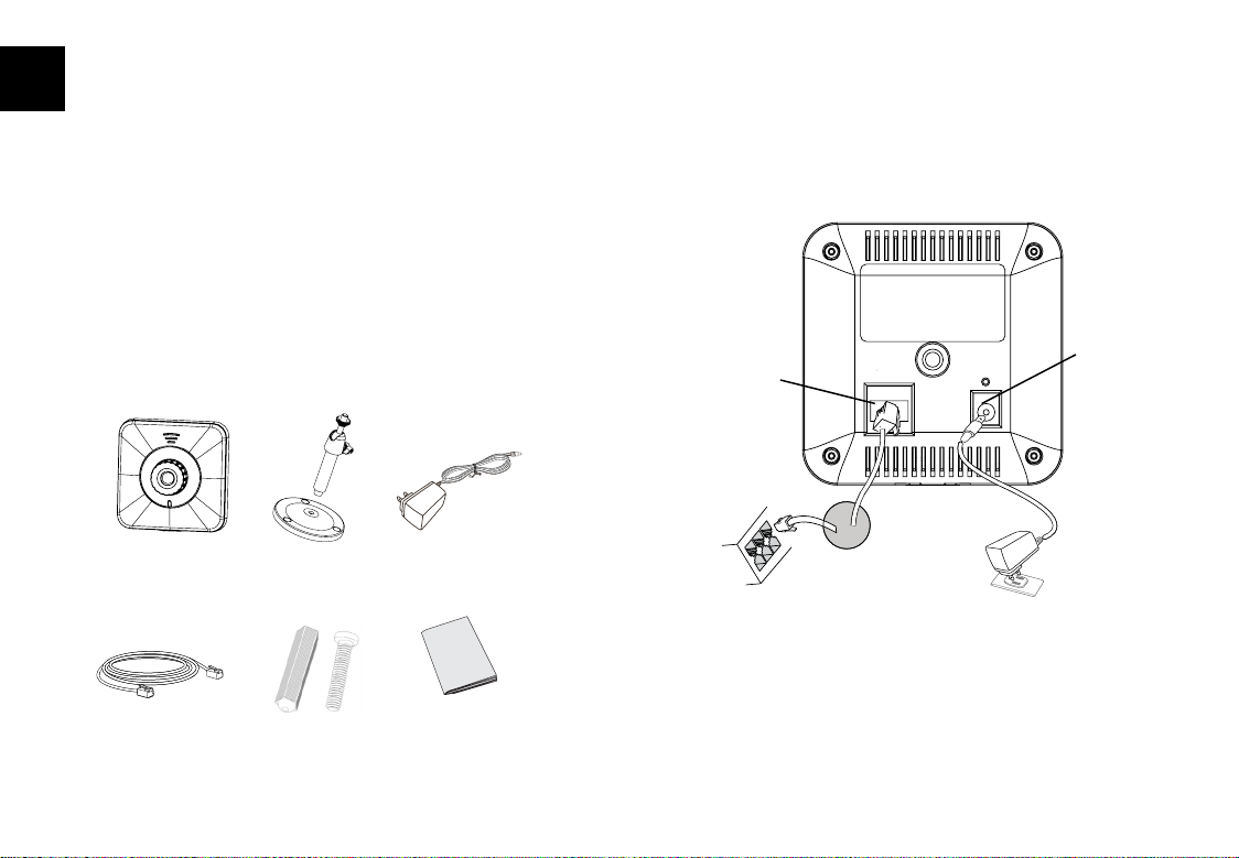
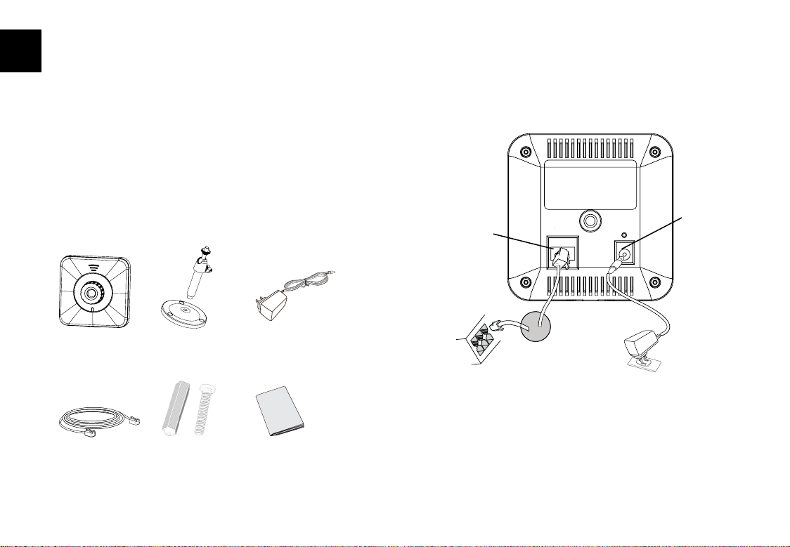
PACKAGE CONTENTS
12V
GXV3615/
GXV3615w
ethernet cAble
MountinG
stAnd
MountinG
screws
Power AdAPter
QuickstArt Guide
Refer to the illustration below when following the
instructions on the next page.
Power Port
Network
Port
12V
Option B: RJ45 Ether-
net
cable to Power over
Ethernet(PoE)
(Not appliable on GXV3615W)
NOTE: For GXV3615, choose Option A if using the power
supply. Or choose Option B if using a Power over Ethernet
(PoE) switch.
switch
Option A:
Power Adapter
To AC Outlet
~1~ ~2~

Option A
Step 1: Insert the power adapter into the 12V DC
port on the GXV3615 series. Plug the other
end of the adapter into an AC power outlet.
Step 2: Plug an RJ45 Ethernet cable into the network
port. Plug the other into a hub, switch or
router.
GXV3615 SERIES CONFIGURATION
Conguring the GXV3615 Series using Microsoft Internet Explorer
Connect the GXV3615 Series to a DHCP
server
S
tep 1: Navigate your browser to:
http://www.grandstream.com/support/gxv_
series_surveillance/general/resources/gs_search.zip
Option B (Not appliable on GXV3615W)
Step 1: Plug an RJ45 Ethernet cable into the network
port. Plug the other end into a Power over
Ethernet (PoE) switch.
Note:
In order to set up the Wi-Fi settings, rst connect to the
camera through the Ethernet port and congure the
WIFI properties using Internet browser.
~3~ ~4~
Step 2: Run the Grandstream GS_Search tool, that
you just downloaded.
Step 3: Click on the button in order to
begin device detection
Step 4: The detected devices will appear in the
Output eld

Step 5: Open Microsoft Internet Explorer on your PC.
Type in the IP in the address bar.
Step 6: A pop-up window will appear with prompts
for a user name and password. The default
administrator user name and password are
both set to “admin” at the default factory
conguration.
Step 7: Once you log into the GXV3615 Series’ web
interface Internet Explorer will indicate that
“This website wants to install the following
add-on: ‘GSViewer.cab’ from Grandstream
Networks, Inc.” Install this add-on by follow-
ing the instructions.
Step 8: Once the installation of GSViewX.cab is
completed, you will see the web page shown
below. Click on the play button to view the
video feed.
~5~ ~6~

Step 9: Click through the menu on the left hand side
of the web UI for more advanced congura-
tion parameters.
Connect the GXV3615 series using Static
IP
If the camera does not get a response from the DHCP
server after 3 minutes, it can be accessed by the de-
fault IP 192.168.1.168
Step 1: Connect your PC and the GXV3615 Series’ to
the same network.
Step 2: Set the IP address of your PC to 192.168.1.X.
Set the Default Gateway of your PC to
255.255.255.0.
Step 3: Open Microsoft Internet Explorer on your PC.
Type 192.168.1.168 in the address bar.
Step 4-7: Please refer to Step 6-9 on Page 5.
Please download the user manual and FAQ for more
detailed conguration instructions:
http://www.grandstream.com
~7~
GXV3615 SERIES SAMPLE
CONNECTION DIAGRAM
DC 12V
Internet
PC
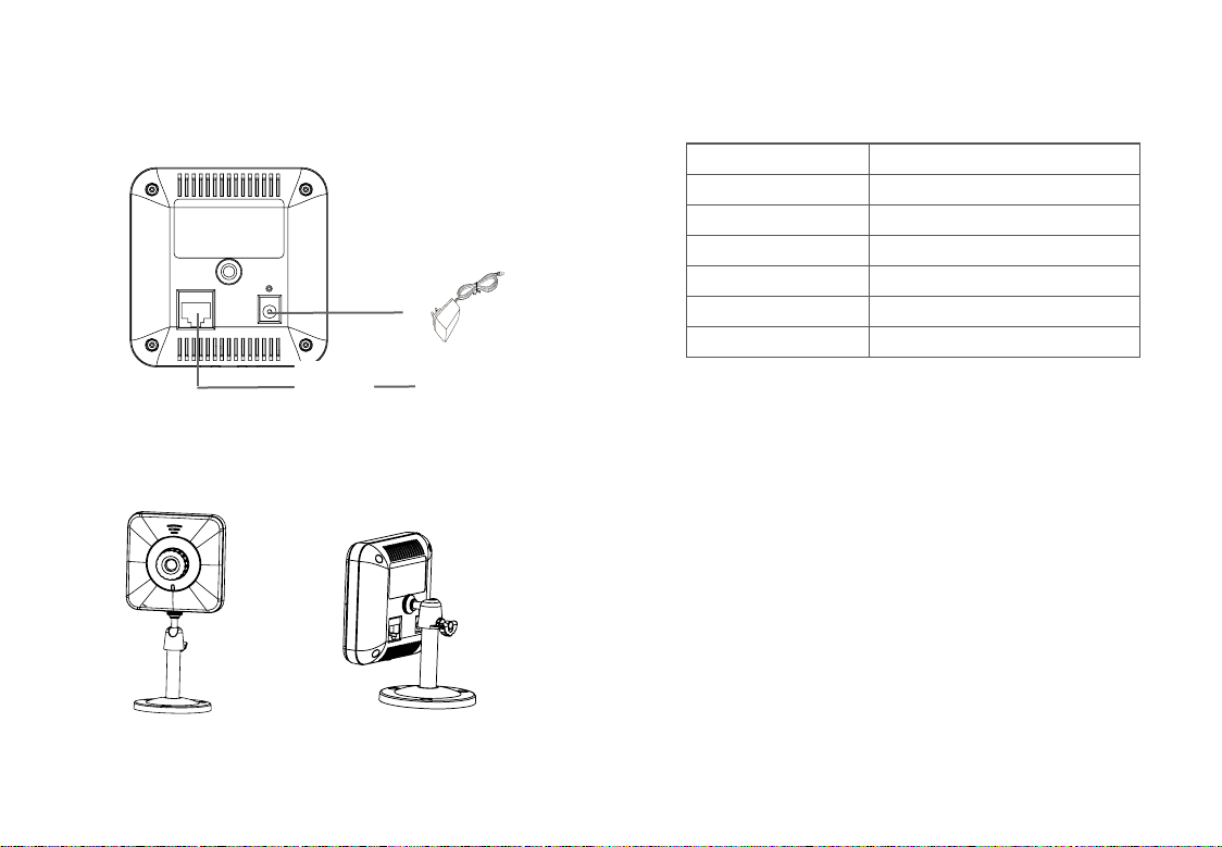
Mount
There are 2 methods to mount GXV3615.
12V
GXV3615 SERIES LENS SPECIFICATIONS
Lens Mount M12
Image Format 1/4”
Image Sensor CMOS
Focal Length 4.5 mm
View Angles 64
Aperture 1.5
Size 14x12.91 mm
o
Bottom Mounting Socket Back Mounting Socket
~9~ ~10~
ES
PRECAUCIONES
ConeXión del GXV3615 SeRie
• No intente abrir, desarmar o modicar la unidad
• No use un adaptador de corriente de otra marca
• No exponga esta unidad a temperaturas fuera de
este rango: -10 C a +55 C
• No exponga esta unidad a condiciones húmedas
fuera del rango de 10 a 90 % RH (no condensadas)
o o
CONTENIDO
12V
GXV3615/
GXV3615w
cAble ethernet
soPorte de
MonturA
tornillos de
MonturA
AdAPtAdor
de corriente
GuíA de
instAlAción ráPidA
Observe la ilustración de abajo cuando siga las
instrucciones en la página siguiente
Puerto de
Puerto de
Red
12V
Opción B: Cable de Red
RJ45 hacia switch PoE
(No aplicable en la
GXV3615W)
Nota: Para el GXV3615, utilice solo una opción A o B
Opción A: Adapta-
dor de corriente hacia
toma de corriente
corriente
~11~ ~12~
 Loading...