

Page 1
Grandstream Networks, Inc.
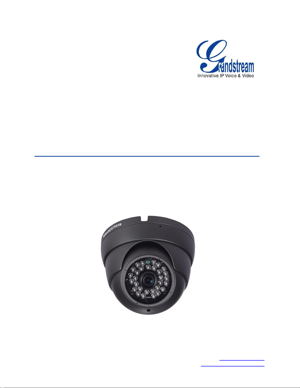
GXV3610_HD/GXV3610_FHD
Mounting and Installation Guide
GXV3610_HD/FHD www.grandstream.com
Mounting and Installation Guide http://esupport.grandstream.com
Page 2

TABLE OF CONTENTS
GXV3610_HD/FHD Mounting and Installation Guide
SAFETY COMPLIANCES ............................................................................................................................ 3
WARRANTY ................................................................................................................................................. 4
EQUIPMENT PACKAGE CONTENTS ......................................................................................................... 5
COMPONENT TERMINOLOGY ................................................................................................................... 6
MOUNTING PROCEDURES ........................................................................................................................ 7
STEP 1 ........................................................................................................................................................ 7
STEP 2 ........................................................................................................................................................ 7
STEP 3 ........................................................................................................................................................ 8
STEP 4 ........................................................................................................................................................ 8
STEP 5 ........................................................................................................................................................ 9
STEP 6 ........................................................................................................................................................ 9
STEP 7 ...................................................................................................................................................... 10
STEP 8 ...................................................................................................................................................... 10
CONNECT YOUR GXV3610_HD/FHD ....................................................................................................... 11
USING THE POWER ADAPTER AS POWER SUPPLY ......................................................................................... 11
USING POE AS POWER SUPPLY ................................................................................................................... 11
INSTALLATION GUIDE ............................................................................................................................. 12
MINIMUM RECOMMENDED COMPUTER SYSTEM REQUIREMENT ..................................................................... 12
CONFIGURE THE GXV3610_HD/FHD VIA WEB BROWSER .......................................................................... 12
CONNECT THE CAMERA TO NETWORK WITH DHCP SERVER (RECOMMENDED) .............................................. 13
CONNECT TO THE CAMERA USING STATIC IP ............................................................................................... 14
Grandstream Networks, Inc. GXV3610_HD/FHD Mounting and Installation Guide Page 2 of 14
Last Updated: 10/2013
Page 3
SAFETY COMPLIANCES
These instructions are intended to assist users with the operation of the GXV3610_HD/FHD and to
instruct on how to avoid dangerous situations or damage to the device.
Warning: Serious injury or death may be caused if any of the warnings below are neglected.
Caution: Injury or damage to the equipment may occur if any of the following caution messages
are neglected.
Warning: Follow these safeguards to
Warning:
Input voltage should meet both the SELV (Safety Extra Low Voltage) and the Limited
Source with DC 12V according to the IEC60950-1 standard. Please refer to the
specifications for more
device installed on the wall or ceiling, make sure that it is firmly
serious injury or
details.
death.
Do not use a third-party power adapter or power
prevent
Caution: Follow these precautions
prevent potential injury or
material damage.
attached.
cord.
to
Power
technical
When the
Make sure that the power supply voltage is correct before using the
Do not drop the device or expose it to physical
Do not expose the device to temperatures outside the range of -20 oC to +50oC when t
is in
Do not expose the device to damp/wet conditions or high electromagnetism
heat accumulation, make sure that your operating environment has
Do not attempt to open, disassemble, or modify the
A few parts (e.g. electrolytic capacitor) of the equipment shall be replaced regularly
average lifetime. The average lifetime varies from the differences between
and usage history. Regular maintenance checks are recommended for
Please contact your dealer for more
Notice:
operation.
camera.
shock.
he d
evice
details.
radiation.
proper ventilation.
device
operating
all
users.
To avoid
according
environments
to their
Grandstream Networks, Inc. GXV3610_HD/FHD Mounting and Installation Guide Page 3 of 14
Last Updated: 10/2013
Page 4

WARRANTY
If you purchased your GXV3610_HD/FHD from a reseller, please contact the company where you
purchased the device for replacement, repair or refund.
If you purchased the product directly from Grandstream, please contact your Grandstream Sales and
Service Representative for a RMA (Return Materials Authorization) number before you return the product.
Grandstream reserves the right to remedy warranty policy without prior notification.
Caution:
Changes or modifications to this product not expressly approved by Grandstream, or operation of this
product in any way other than as detailed by this User Manual, could void your manufacturer warranty.
Please do not use a different power adaptor with the GXV3610_HD/FHD as it may cause damage to the
products and void the manufacturer warranty.
This document is subject to change without notice. The latest electronic version of this user manual is
available for download at:
http://www.grandstream.com/products/surveillance/GXV3610hd/documents/GXV3610HD_FHD_Mou
nting_Installation_Guide.pdf/
Reproduction or transmittal of the entire or any part, in any form or by any means, electronic or print, for
any purpose is not permitted without the express written permission of Grandstream Networks, Inc.
Grandstream Networks, Inc. GXV3610_HD/FHD Mounting and Installation Guide Page 4 of 14
Last Updated: 10/2013
Page 5
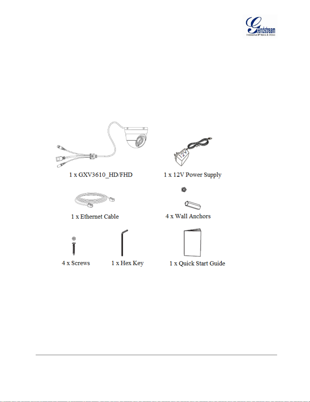
EQUIPMENT PACKAGE CONTENTS
The GXV3610_HD/FHD package contains:
GXV3610_HD/FHD IP Camera
12V DC Universal Power Adaptor
Ethernet Cable
1 Hex Key and 4 Screws and Wall Anchors
Quick Installation Guide
Grandstream Networks, Inc. GXV3610_HD/FHD Mounting and Installation Guide Page 5 of 14
Last Updated: 10/2013
Page 6

COMPONENT TERMINOLOGY
Grandstream Networks, Inc. GXV3610_HD/FHD Mounting and Installation Guide Page 6 of 14
Last Updated: 10/2013
Page 7

MOUNTING PROCEDURES
Step 1
Take out the device and all the accessories. Refer to equipment package content section for the item list.
Use the hex tool to loosen the collar locking screw by turning counter-clockwise for a few turns.
NOTE: Do not completely remove the screw.
Step 2
Loosen the locking collar by turning counter-clockwise.
Grandstream Networks, Inc. GXV3610_HD/FHD Mounting and Installation Guide Page 7 of 14
Last Updated: 10/2013
Page 8

Step 3
Separate the U-collar and the locking collar from the camera dome.
Step 4
Place the mounting template on the desired mounting surface as a reference. If not using wall anchors,
please skip this step. If using wall anchors, use a drill to make the hole at the four screw locations to be
approximately 7mm and then insert the wall anchor into the hole. Remove template when finished.
Grandstream Networks, Inc. GXV3610_HD/FHD Mounting and Installation Guide Page 8 of 14
Last Updated: 10/2013
Page 9

Step 5
Use a Philips screwdriver to secure the four screws for the camera base. NOTE: Do not completely tighten
the screws in this step. Please make sure there is sufficient space for the power connectors. If the power
connectors are going inside the wall, then the screws could be fully secured in this step.
Step 6
Place the power connectors through the slot behind the camera base (or through the wall for in-wall
installation) and hold the camera dome on the camera base. After finish positioning the power connectors,
tighten the four screws.
Grandstream Networks, Inc. GXV3610_HD/FHD Mounting and Installation Guide Page 9 of 14
Last Updated: 10/2013
Page 10

Step 7
Insert the U-collar follow by the locking collar. Turn the locking collar clockwise for three turns to loosely
secure the camera. Adjust the camera to the desired position. Please make sure the microphone is on the
bottom of the camera dome to get the correct video orientation. Please also adjust the U-collar so the
opening is not blocking the IR LED or light sensor. Fully secure the locking collar when finished.
Step 8
Tighten the collar locking screw with the hex tool by turning clockwise. Mounting is complete.
Grandstream Networks, Inc. GXV3610_HD/FHD Mounting and Installation Guide Page 10 of 14
Last Updated: 10/2013
Page 11

CONNECT YOUR GXV3610_HD/FHD
Using the Power Adapter as power supply
Connect the RJ-45 Ethernet cable to the NETWORK port of the GXV3610_HD/FHD
Connect the other end of the RJ-45 cable to your network (switch or router or PC)
Connect the power supply to the DC 12V power jack on the back of the GXV3610_HD/FHD
Using PoE as power supply
Connect the RJ-45 Ethernet cable to the NETWORK port of GXV3610_HD/FHD
Connect the other end of the RJ-45 cable to your PoE switch.
Please refer to following connection diagram to hook up the camera.
Grandstream Networks, Inc. GXV3610_HD/FHD Mounting and Installation Guide Page 11 of 14
Last Updated: 10/2013
Page 12

INSTALLATION GUIDE
Minimum Recommended Computer System Requirement
To install GXV3610_HD/FHD, you have to have a computer, PC recommend.
The minimum recommended PC system requirement listed below:
Windows XP, Windows Vista, Windows 7 and Windows 8
CPU: Intel Pentium 4 or higher, 2 GHz
RAM: 1 GB (4 GB recommended for larger systems)
Support for DirectX 8.0 and above.
Configure the GXV3610_HD/FHD via Web Browser
The GXV3610_HD/FHD has embedded Web server to respond to HTTP GET/POST requests. Embedded
HTML pages allow user to configure the IP camera through Microsoft Internet Explorer (7.0 or above),
Firefox and Chrome (plug-in from Grandstream required).
Download Plug-in from Grandstream website:
http://www.grandstream.com/products/tools/surveillance/webcontrl_plugin.zip
NOTE:
Apple Safari is NOT yet supported and status pending.
Please temporarily disable Antivirus or Internet Security Software when download and install the
Grandstream Plug-in Software.
Grandstream Networks, Inc. GXV3610_HD/FHD Mounting and Installation Guide Page 12 of 14
Last Updated: 10/2013
Page 13

Connect the Camera to network with DHCP server (Recommended)
The GXV3610_HD/FHD by default enabled as DHCP client, it will automatically get IP address from the
network with DHCP server running. User can know the IP address assigned to the camera from DHCP
server log or using the Grandstream GS_Search tool.
1. Download the GS_Search tool from Grandstream website:
http://www.grandstream.com/products/tools/surveillance/GS_Search.zip
2. Run the Grandstream GS_Search tool by double click the unzipped “GS_Search.exe”.
3. Click on the “Search” button to begin device detection
4. The detected devices will appear in the output field like below
5. Double click the column of the detected camera, the browser will automatically open and link to the
device IP and the web configuration page.
6. The browser will ask for plug-in or ActiveX if not installed, otherwise it will get to Home page and
start to show the video captured by the camera (by default the camera enabled anonymous access)
7. Click “Configuration”, the browser will ask credentials to authorize configuration.
8. Enter the administrator user name and password to access the Web Configuration Interface, the default
user name and password are both set to admin.
9. In step 6, browser will indicate that “This website wants to install the following add-on:
GSViewerX.cab from Grandstream Networks Inc.”, allow the installation.
10. The plug-in can be download here:
http://www.grandstream.com/products/tools/surveillance/webcontrl_plugin.zip
NOTE:
Please temporarily disable Antivirus or Internet Security Software and close all browsers when
download and install the Grandstream Plug-in Software.
Grandstream Networks, Inc. GXV3610_HD/FHD Mounting and Installation Guide Page 13 of 14
Last Updated: 10/2013
Page 14

Connect to the Camera using Static IP
If no DHCP server in the network, or the camera does not get IP from DHCP server, user can connect the
camera to a computer directly, using static IP to configure the camera.
The default IP, if no DHCP server; or DHCP offer time out (3 minutes), is 192.168.1.168
1. Connect the computer RJ-45 via an Ethernet cable directly to the IP camera GXV3610_HD/FHD.
2. Configure the computer using Static IP: 192.168.1.XXX (1<XXX<255, but NOT 168) and configure
the “Subnet mask” to “255.255.255.0”. Leave the “Default Gateway” to “Blank” like below:
3. Power on the GXV3610_HD/FHD.
4. Start the browser when the network connection is up.
5. Enter 192.168.1.168 in the address bar of the browser.
6. The browser will ask for plug-in or ActiveX if not installed, otherwise it will get to Home page and
start to show the video captured by the camera (by default the camera enabled anonymous access)
7. Click “Configuration”, the browser will ask credentials to authorize configuration.
8. Enter the administrator user name and password to access the Web Configuration Interface, the default
user name and password are both set to admin.
9. The plug-in can be downloaded from here:
http://www.grandstream.com/products/tools/surveillance/webcontrl_plugin.zip
NOTE:
Please temporarily disable Antivirus or Internet Security Software and close all browsers when
download and install the Grandstream Plug-in Software.
Grandstream Networks, Inc. GXV3610_HD/FHD Mounting and Installation Guide Page 14 of 14
Last Updated: 10/2013
 Loading...