

Grandstream GXV3501 User Manual
Grandstream Networks, Inc.
GXV3501/GXV3504 User Manual
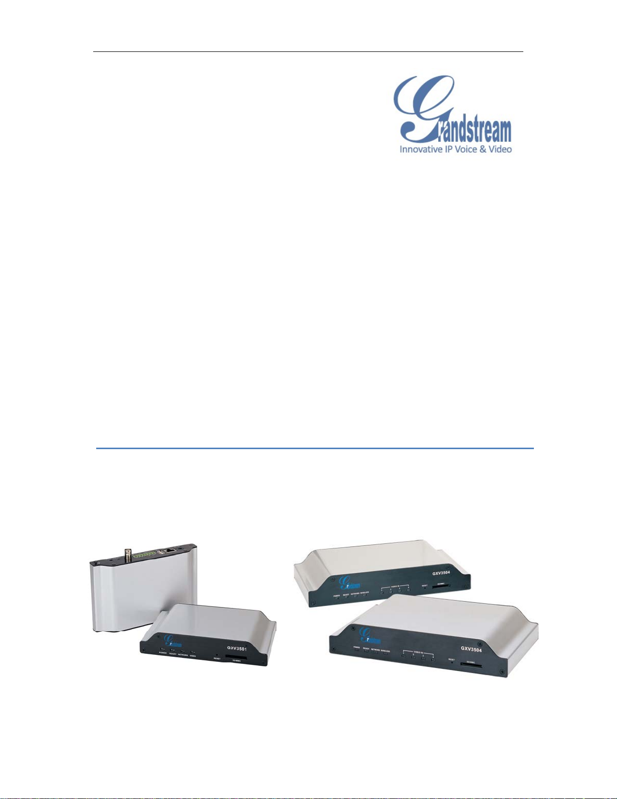
GXV3501/GXV3504 Digital Video Server
Safety Instructions
These instructions are intended to assist users with the operation of the GXV3501/GXV3504
and also to instruct on how to avoid dangerous situations or damage to the device.
Warnings: Serious injury or death may be caused if any of the warnings below are neglected.
Cautions: Injury or damage to the equipment may occur if any of the following caution
messages are neglected.
Warnings Follow these safeguards to prevent
serious injury or death.
Warnings:
Input voltage should meet both the SELV (Safety Extra Low Voltage) and the Limited Power
Source with DC 12V according to the IEC60950-1 standard. Please refer to the technical
specifications for more details.
Do not use a third-party power adapter or power cord
When the device is installed on the wall or ceiling, make sure that it is firmly attached.
Cautions Follow these precautions to
prevent potential injury or material
damage.
Notice:
Make sure that the power supply voltage is correct before using the camera.
Do not drop the device or expose it to physical shock.
Do not expose the device to temperatures outside the range of -10
device is in operation.
Do not expose the device to damp/wet conditions or high electromagnetism radiation.
To avoid heat accumulation, make sure that your operating environment has proper
ventilation.
Do not attempt to open, disassemble, or modify the device
A few parts (e.g. electrolytic capacitor) of the equipment shall be replaced regularly according
to their average life time. The average life time varies from the differences between operating
environments and usage history. Regular maintenance checks are recommended for all
users. Please contact your dealer for more details.
Firmware 1.0.4.6 Page 2 of 36
Grandstream Networks, Inc. 09/2010
o
C to +60oC when the

GXV3501/GXV3504 Digital Video Server
Contents
W elcome ......................................................................................................................................................... 4
Package Contents ............................................................................................................................................ 5
Product Overview ........................................................................................................................................... 7
GXV3501Front Panel ............................................................................................................................. 7
GXV3501Back panel .............................................................................................................................. 7
GXV3501 Sample Connection Diagram ................................................................................................. 8
GXV3504 Front Panel ............................................................................................................................ 8
GXV3504 Back Panel ....................................... ... .. ... .. .............................. ... .. ... ...................................... 9
GXV3504 Sample Connection Diagram ................................................................................................. 9
GXV3501/GXV3504 Key Features ................................. ... .............................. ... .. ... ............................ 10
Installation Guide ........................ ................................. .. ................................. .............................................. 11
Minimum Recommended System Requirement .............. ... .. ................................. .. ... ... .. ..................... 11
Connect your GXV3501/GXV3504...................................................................................................... 11
Configuring the GXV3501/GXV3504 via Web Browser ............................................................................. 13
Access GXV3501/GXV3504 Web Configuration Menu .............. .. ............................... .. ... .. ................ 13
Connect the Camera to DHCP server. ................................................................................................... 13
Connect to the Camera using Static IP. ................................................................................................. 13
GXV350x Home Web Page ....................................................... ... .. ... .............................. ... .. ... ............. 14
GXV3501/GXV3504 System Page ................ ... ... .. .............................. ... .. ... .. ............................... .. ...... 16
GXV3501/GXV3504 Video & Audio Page .......................................................................................... 17
GXV3501/GXV3504 Networking Page – Assign an IP to GXV3501/GXV3504 ................................ 18
GXV3501 Wifi Page ............................................................................................................................. 19
GXV3501/GXV3504 DDNS Page ............................................... .. ... .. ............................... .. ... ............. 20
GXV3501/GXV3504 SIP Page ....................... .. ... .. ............................................................................... 20
GXV3501/GXV3504 Status Page ................... .............................. .. ... .. ... .............................. ... .. ... ........ 22
GXV3501/GXV3504 User Management Page ..................................................................................... 23
GXV3501/GXV3504 Maintenance Page ..................................................... ......................................... 24
GXV3501/GXV3504 SMTP Page .................................................................. .. ... .. ... ............................ 25
GXV3501/GXV3504 FTP Page .................................. ... .. ............................................................... ...... 25
GXV3501/GXV3504 PTZ Page ............................................................................ ... .. ... ....................... 26
GXV3501/GXV3504 Alarm Event ....................................................................................................... 27
GXV3501/GXV3504 Motion Detection ....................................... .............................. ... .. ... .. ................ 30
GXV3501/GXV3504 System Log ................................. .. ............................... .. ... ................................. 31
FAQ ............................................................................................................................................................... 33
Firmware 1.0.4.6 Page 3 of 36
Grandstream Networks, Inc. 09/2010

GXV3501/GXV3504 Digital Video Server
Welcome
The GXV3501/3504 is a powerful, next generation digital video surveillance encoder. The
GXV3501/3504 provides an easy to manage multi camera IP solution.
The GXV3501/3504 combines cutting-edge technology, including: support for SIP, H.264 BP,
2- way audio, and PoE, for best-in-class scalability, ease of integration and security. The
unique incorporation of TCP/IP protocols creates sophisticated, flexible networking and
remote control abilities.
The GXV3501/3504 features the advanced functionality of embedded analytics (including
motion detection and video loss) and powerful pre-recording. Grandstream’s flexible video
management software enables users to monitor multiple environments in one easy to use
application. The intuitive web interface lets users easily access, manage, view and record live
video streams from the device.
The GXV3501/3504 is a robust surveillance solution for small to medium sized offices and
enterprise environments.
Firmware 1.0.4.6 Page 4 of 36
Grandstream Networks, Inc. 09/2010
GXV3501/GXV3504 Digital Video Server
Package Contents
Items in the GXV3501 package:
• GXV3501 – 1-channel digital video server
• 12V DC power Adapter
• 8-pin terminal block connector – 8-pin connector block for connecting external devices,
such as infrared detector, and smoke detector, to Alarm IN, Alarm OUT and RS485
pins.
• Quick installation guide
Items in the GXV3504 package:
• GXV3504 – 4-channel digital video server
• 12V DC power Adapter
• 2 12-pin terminal block connectors – 12-pin connector block for connecting external
devices, such as infrared detector, smoke detector, to Alarm IN, Alarm OUT, RS485
pins and etc.
• Quick installation guide
Firmware 1.0.4.6 Page 5 of 36
Grandstream Networks, Inc. 09/2010
GXV3501/GXV3504 Digital Video Server
Firmware 1.0.4.6 Page 6 of 36
Grandstream Networks, Inc. 09/2010
GXV3501/GXV3504 Digital Video Server
Product Overview
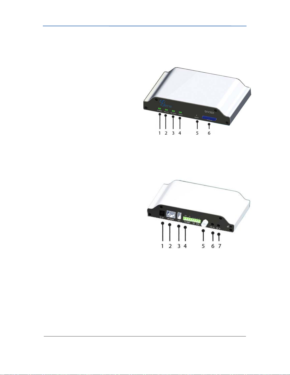
GXV3501Front Panel
1 POWER – The indicator will keep
green if the power is on.
2 READY –
green if the device is ready.
3 NETWORK –
green if there is data transmission with
the internet or stay solid green if there
is no data transmission.
4 VIDEO –
green when there is video input.
5 RESET -
seconds to perform a factory reset.
6 SD/MMC – The SD/MMC slot.
The indicator will light up
The indicator will flash
The indicator will light up
Press the Reset button for 6
GXV3501Back panel
1 DC 12V – 12V DC power port; UL
Certified.
2 NETWORK – 10/100 Switch LAN port
for connecting to Ethernet.
3 USB – USB port for flash / hard drives.
Includes hot-swap support.
4 ALARM IN – 1 Alarm Input port for
alarm equipment, ie. Infrared detector.
ALARM OUT – 1 Alarm Input port for
detectors, ie. Sirens.
VG – 12V DC power output port for other devices.
RS-485 – 1 PTZ connector.
5 VIN – 1 BNC (Voltage: 1.0V p-p, Resistance 75) port for video input3.5mm port for audio
output devices, ie. Speakers.
6 LINE OUT – 3.5mm port for audio output devices, ie. Speakers.
7 MIC IN – 3.5mm port for audio input devices, ie. Microphones.
Firmware 1.0.4.6 Page 7 of 36
Grandstream Networks, Inc. 09/2010
GXV3501/GXV3504 Digital Video Server
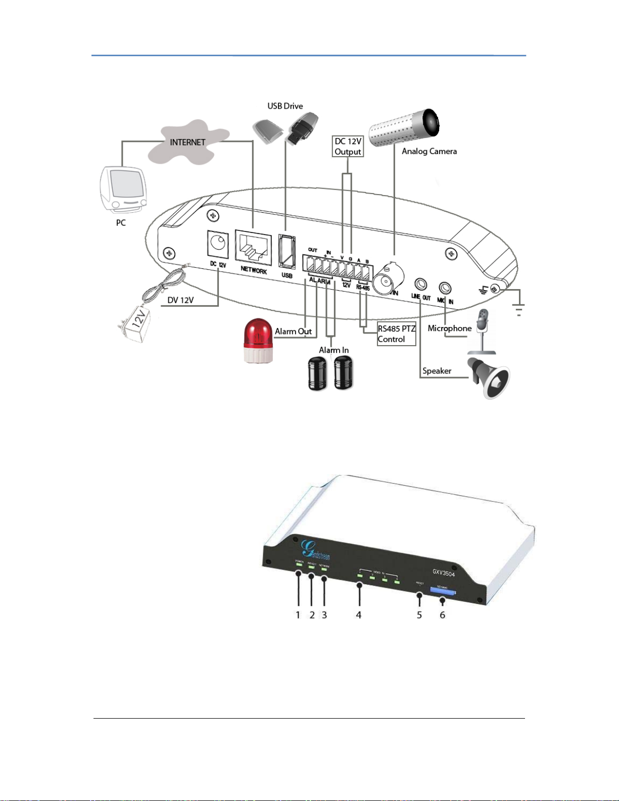
GXV3501 Sample Connection Diagram
GXV3504 Front Panel
1 POWER – The indicator will
stay green if power is on.
2 REDAY – The indicator will light
up green if the device is ready.
3 NETWORK – The indicator will
flash green if there is data.
transmission with the internet or
stay solid green if there is no
data transmission.
4 VIDEO IN – 4 Video-In
indicators. The indicators will light
up green when video sources are connected.
5 RESET – Press the Reset button for 6 seconds to perform a factory reset.
6 SD/MMC – The SD/MMC slot.
Firmware 1.0.4.6 Page 8 of 36
Grandstream Networks, Inc. 09/2010
GXV3501/GXV3504 Digital Video Server
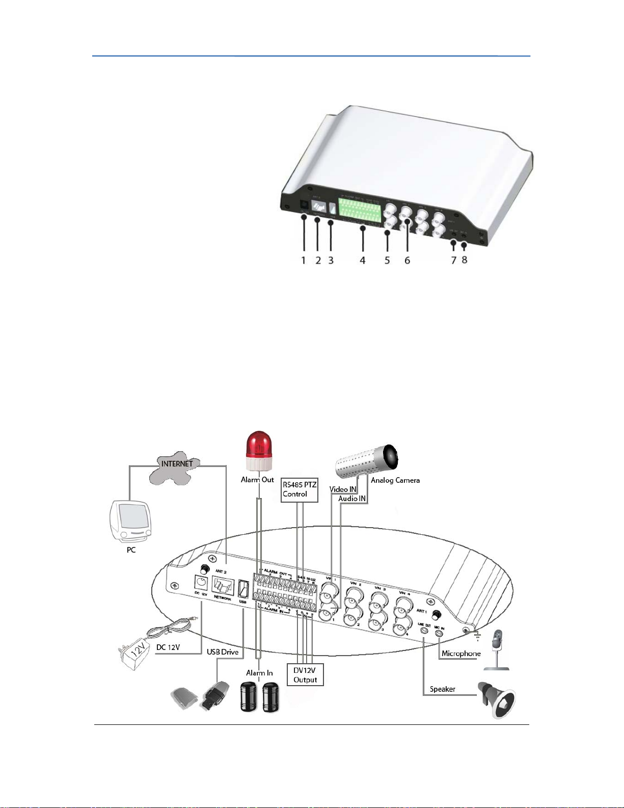
GXV3504 Back Panel
1 DC 12V – 12V DC power port;
UL Certified.
2 NETWORK – 10/100 Switch
LAN Ethernet port.
3 USB – USB port for USB flash /
hard drives.
4 ALARM IN – 4 Alarm Input
ports for alarm equipment, ie.
Infrared / Smoke Detectors.
ALARM OUT – 4 Alarm Input
ports for detectors, ie. Sirens.
RS-485 – 1 PTZ connector.
RS-232 – Persevered connectors.
VGGG – 12V DC power output port for other devices.
5 AIN – 4 BNC (Voltage: 1.0V p-p, Resistance 75) port for audio input.
6 VIN – 4 BNC (Voltage: 1.0V p-p, Resistance 75) port for video input.
7 LINE OUT – 3.5mm port for audio output devices, ie. Speakers.
8 MIC-IN – 3.5mm port for audio input devices, ie. Microphones.
GXV3504 Sample Connection Diagram
Firmware 1.0.4.6 Page 9 of 36
Grandstream Networks, Inc. 09/2010

GXV3501/GXV3504 Digital Video Server
GXV3501/GXV3504 Key Features
The table below lists the key features the GXV3501/GXV3504 Supports.
Feature GXV3501 GXV3504
Channels 1 4
Video Compression H.264 BP @Level 3.0, JPEG, Motion JPEG
Max Video Resolution Full D1: 720 x 576(PAL) 720 x 480 (NTSC)
Max Frame Rate in
Max Video Resolution
Video Bit Rate 32 Kbps – 2 Mbps
Video Input 1 BNC
Audio Input 3.5mm LINE IN 4 (BNC), 3.5mm LINE IN
Audio Output 3.5mm LINEOUT
Audio Compression G.711
Alarm Input 1 4
Alarm Output 1 4
PTZ Control Yes
Serial Ports RS485 RS485/ RS232
Embedded Analytics Motion Detection (up to 16 target areas), video loss (pending)
Pre-/post alarm buffer 24MB 24MB (per channel)
Snapshots Can be sent via email/FTP when events are triggered.
Multi-streaming-rate
for Preview and
Recording
Security Video watermark, HTTPS, password
Power over Ethernet
(PoE)
Peripheral Ports SD 2.0, USB Host 2.0
SIP/VoIP Support Yes
Weight 0.6kg 1.0kg
Temperature /
Humidity
Power Output: 12VDC/1.5A; Input: 100–240VAC, 50–60Hz
Compliance FCC Part15, Subpart B Class B; EN 55022 Class B,
30fps/25fps at D1 (NTSC/PAL) 75fps/62.5fps (NTSC/PAL):
4 Ports at CIF at full rate, or 2
Ports at D1 & 2 Ports at CIF at
full rate , or 4 ports at D1 at
reduced rate
4 BNC
(voltage1.0Vp-p,resistance75)
(voltage 1.0Vp-p, resistance75)
Yes
Standard, IEEE 802.3af Class 3
-10oC - +55oC (14oF-131oF)
Humidity 10–90% RH (non–condensing)
EN61000-3-2, EN61000-3-3, EN 55024, EN60950-1; C-tick
AS/NZS CISPR 22, CISPR 24
Firmware 1.0.4.6 Page 10 of 36
Grandstream Networks, Inc. 09/2010

GXV3501/GXV3504 Digital Video Server
Installation Guide
Minimum Recommended System Requirement
• Windows 2000 Server Professional, Windows XP, Windows Vista.
• CPU: Intel Pentium 4 or higher, 2 GHz.
• RAM: 1 GB (4 GB recommended for larger systems).
• Support for DirectX 8.0 and above.
.
Connect your GXV3501/GXV3504
Using the Power adapter as power supply
• Connect the video output of an analog camera to the VIN port on the GXV3501/3504
using a BNC (75) cable. If the analog camera has audio output, connect the audio
output to the AIN port on the GXV3504 (GXV3501 does not support audio input).
• Connect an RJ 45 cable to the NETWORK port of the GXV3501/3504
• Connect the other end of the RJ 45 cable to your network or PC directly
• Connect the power supply to the DC 12V power jack on the back of the
GXV3501/3504
• Connect the other end of the power supply to a wall outlet. The POWER indicator will
light green
• The NETWORK indicator will light green within 5 seconds to indicate that a
connection to the internet has been established.
• The GXV3501/3504 is ready when the READY indicator lights up green.
• The VIDEO IN indicator will light up when the video inputs are connected to a video
source.
Using PoE as power supply:
• Connect the video output of an analog camera to the VIN port on the GXV3501/3504
using BNC (75) cable. If the analog camera has an audio output, you should
connect it to the AIN port on GXV3504 (GXV3501 does not support audio input).
• Connect a RJ 45 cable to the NETWORK port of GXV3501/3504
• Connect the other end of the RJ 45 cable to a PoE switch. The POWER indicator will
light solid green
• The NETWORK indicator will light green within 5 seconds to indicate that a
connection to the internet has been established.
• The GXV3501/3504 is ready when the READY indicator is solid green
• The VIDEO IN indicator will light up when the video inputs are connected to a video
source.
NOTE: If you are going to connect the device to a hub/switch/router, please use a
Firmware 1.0.4.6 Page 11 of 36
Grandstream Networks, Inc. 09/2010
 Loading...