

Page 1
Grandstream Networks, Inc.
GWN7600
Mid-Tier 802.11ac Wave-2 WiFi Access Point
User Manual
Page 2

P a g e | 2
GWN7600 User Manual
Version 1.0.4.12
COPYRIGHT
©2017 Grandstream Networks, Inc. http://www.grandstream.com
All rights reserved. Information in this document is subject to change without notice. Reproduction or
transmittal of the entire or any part, in any form or by any means, electronic or print, for any purpose
without the express written permission of Grandstream Networks, Inc. is not permitted.
The latest electronic version of this guide is available for download here:
http://www.grandstream.com/support
Grandstream is a registered trademark and Grandstream logo is trademark of Grandstream Networks, Inc.
in the United States, Europe and other countries.
CAUTION
Changes or modifications to this product not expressly approved by Grandstream, or operation of this
product in any way other than as detailed by this guide, could void your manufacturer warranty.
WARNING
Please do not use a different power adaptor with devices as it may cause damage to the products and void
the manufacturer warranty.
Page 3

P a g e | 3
GWN7600 User Manual
Version 1.0.4.12
FCC Caution
Any Changes or modifications not expressly approved by the party responsible for compliance could void
the user's authority to operate the equipment.
This device complies with part 15 of the FCC Rules. Operation is subject to the following two conditions: (1)
This device may not cause harmful interference, and (2) this device must accept any interference received,
including interference that may cause undesired operation.
Note: This equipment has been tested and found to comply with the limits for a Class B digital device,
pursuant to part 15 of the FCC Rules. These limits are designed to provide reasonable protection against
harmful interference in a residential installation. This equipment generates, uses and can radiate radio
frequency energy and, if not installed and used in accordance with the instructions, may cause harmful
interference to radio communications. However, there is no guarantee that interference will not occur in a
particular installation. If this equipment does cause harmful interference to radio or television reception,
which can be determined by turning the equipment off and on, the user is encouraged to try to correct the
interference by one or more of the following measures:
• Reorient or relocate the receiving antenna.
• Increase the separation between the equipment and receiver.
• Connect the equipment into an outlet on a circuit different from that to which the receiver is
connected.
• Consult the dealer or an experienced radio/TV technician for help.
Page 4

P a g e | 4
GWN7600 User Manual
Version 1.0.4.12
GNU GPL INFORMATION
GWN7600 firmware contains third-party software licensed under the GNU General Public License (GPL).
Grandstream uses software under the specific terms of the GPL. Please see the GNU General Public
License (GPL) for the exact terms and conditions of the license.
Grandstream GNU GPL related source code can be downloaded from Grandstream web site:
http://www.grandstream.com/support/faq/gnu-general-public-license
Page 5

P a g e | 5
GWN7600 User Manual
Version 1.0.4.12
Table of Contents
DOCUMENT PURPOSE ............................................................................................... 11
CHANGE LOG .............................................................................................................. 12
Firmware Version 1.0.4.12 ................................................................................................................... 12
Firmware Version 1.0.3.25 ................................................................................................................... 12
Firmware Version 1.0.3.19 ................................................................................................................... 12
Firmware Version 1.0.1.31 ................................................................................................................... 12
WELCOME ................................................................................................................... 13
PRODUCT OVERVIEW ................................................................................................ 14
Technical Specifications ....................................................................................................................... 14
INSTALLATION ............................................................................................................ 16
Equipment Packaging .......................................................................................................................... 16
GWN7600 Access Point Ports ............................................................................................................. 16
Power and Connect GWN7600 Access Point ...................................................................................... 17
Warranty ............................................................................................................................................... 17
Wall and Ceiling Mount Installation ...................................................................................................... 18
Wall Mount .................................................................................................................................... 18
Ceiling Mount ................................................................................................................................ 19
GETTING STARTED ..................................................................................................... 20
LED Patterns ........................................................................................................................................ 20
Discover the GWN7600 ....................................................................................................................... 21
Method1: Discover the GWN7600 using its MAC address ........................................................... 21
Method 2: Discover the GWN7600 using GWN Discovery Tool ................................................... 22
Use the Web GUI ................................................................................................................................. 22
Access Web GUI .......................................................................................................................... 23
WEB GUI Languages ................................................................................................................... 23
Page 6

P a g e | 6
GWN7600 User Manual
Version 1.0.4.12
Overview Page ............................................................................................................................. 24
Save and Apply Changes ............................................................................................................. 25
USING GWN7600 AS STANDALONE ACCESS POINT .............................................. 26
Connect to GWN7600 Default Wi-Fi Network...................................................................................... 26
Using GWN7600 as Master Access Point Controller ................................................ 27
Login Page ........................................................................................................................................... 27
Discover and Pair Other GWN7600 Access Point ............................................................................... 28
Failover Master .................................................................................................................................... 31
Client Bridge ........................................................................................................................................ 32
NETWORK GROUPS ................................................................................................ ... 33
Network Groups ................................................................................................................................... 33
Create an Additional SSID under same Network Group ...................................................................... 40
CLIENTS CONFIGURATION ........................................................................................ 42
Clients .................................................................................................................................................. 42
Clients Access ...................................................................................................................................... 42
Time Policy ........................................................................................................................................... 44
Banned Clients ..................................................................................................................................... 45
LED SCHEDULE .......................................................................................................... 46
CAPTIVE PORTAL ....................................................................................................... 48
Policy.................................................................................................................................................... 48
Files...................................................................................................................................................... 50
Clients .................................................................................................................................................. 52
BANDWIDTH RULES ................................................................................................... 53
SYSTEM SETTINGS ..................................................................................................... 55
Maintenance ........................................................................................................................................ 55
Basic ............................................................................................................................................. 55
Page 7

P a g e | 7
GWN7600 User Manual
Version 1.0.4.12
Upgrade ........................................................................................................................................ 55
Access .......................................................................................................................................... 56
Syslog ........................................................................................................................................... 56
Logserver ...................................................................................................................................... 57
Debug .................................................................................................................................................. 59
Capture ......................................................................................................................................... 59
Core Files ..................................................................................................................................... 61
Ping/Traceroute ............................................................................................................................ 61
Syslog ........................................................................................................................................... 62
Email/Notification ................................................................................................................................. 63
UPGRADING AND PROVISIONING ............................................................................ 67
Upgrading Firmware ............................................................................................................................ 67
Upgrading via WEB GUI ............................................................................................................... 67
Upgrading Slave Access Points ........................................................................................................... 67
Provisioning and Backup ..................................................................................................................... 69
Download Configuration ............................................................................................................... 69
Upload Configuration .................................................................................................................... 69
Configuration Server (Pending) .................................................................................................... 69
Reset and reboot ................................................................................................................................. 70
Syslog .................................................................................................................................................. 70
EXPERIENCING THE GWN7600 WIRELESS ACCESS POINT .................................. 71
Page 8

P a g e | 8
GWN7600 User Manual
Version 1.0.4.12
Table of Tables
Table 1: GWN7600 Technical Specifications .............................................................................................. 14
Table 2: GWN7600 Equipment Packaging .................................................................................................. 16
Table 3: GWN7600 Ports Description ......................................................................................................... 16
Table 4: LED Patterns ................................................................................................................................. 20
Table 5: Overview ........................................................................................................................................ 24
Table 6: Device Configuration ..................................................................................................................... 29
Table 7: Basic configuration of group .......................................................................................................... 34
Table 8: Wi-Fi .............................................................................................................................................. 35
Table 9: Time Policy Parameters ................................................................................................................ 44
Table 10: LEDs ............................................................................................................................................ 46
Table 11: Policy Parameters ........................................................................................................................ 49
Table 12: Bandwidth Rules.......................................................................................................................... 53
Table 13: Basic ............................................................................................................................................ 55
Table 14: Upgrade ....................................................................................................................................... 55
Table 15: Access ......................................................................................................................................... 56
Table 16: Syslog Parameters ...................................................................................................................... 57
Table 17: Debug .......................................................................................................................................... 60
Table 18: Email Setting ............................................................................................................................... 64
Table 19: Email Events ................................................................................................................................ 65
Table 20: Network Upgrade Configuration .................................................................................................. 67
Page 9

P a g e | 9
GWN7600 User Manual
Version 1.0.4.12
Table of Figures
Figure 1: GWN7600 Ports ........................................................................................................................... 16
Figure 2: Connecting GWN7600 ................................................................................................................. 17
Figure 3: Wall Mount – Steps 1 & 2 ............................................................................................................ 18
Figure 4: Wall Mount – Steps 3 & 4 ............................................................................................................ 18
Figure 5: Wall Mount – Steps 5 & 6 ............................................................................................................ 18
Figure 6: Ceiling Mount – Steps 1 & 2 ........................................................................................................ 19
Figure 7: Ceiling Mount – Step 3 ................................................................................................................ 19
Figure 8: Ceiling Mount – Step 4 ................................................................................................................ 19
Figure 9: Ceiling Mount – Steps 5 & 6 ........................................................................................................ 19
Figure 10: Discover the GWN7600 using its MAC Address ........................................................................ 21
Figure 11: GWN Discovery Tool .................................................................................................................. 22
Figure 12: GWN7600 Web GUI Login Page ............................................................................................... 23
Figure 13: GWN7600 Web GUI Language (Login page) ............................................................................ 23
Figure 14: GWN7600 Web GUI Language (Web Interface) ....................................................................... 24
Figure 15: GWN7600's Dashboard ............................................................................................................. 24
Figure 16: Apply Changes ........................................................................................................................... 25
Figure 17: MAC Tag Label .......................................................................................................................... 26
Figure 18: Login Page ................................................................................................................................. 27
Figure 19: Setup Wizard ............................................................................................................................. 28
Figure 20: Discover and Pair GWN7600 ..................................................................................................... 28
Figure 21: Discovered Devices ................................................................................................................... 29
Figure 22: GWN7600 Online ....................................................................................................................... 29
Figure 23: Failover Master .......................................................................................................................... 31
Figure 24: Failover Mode GUI ..................................................................................................................... 32
Figure 25: Client Bridge .............................................................................................................................. 32
Figure 26: Network Group ........................................................................................................................... 33
Figure 27: Add a New Network Group ........................................................................................................ 34
Figure 28: Device Membership ................................................................................................................... 38
Figure 29: WiFi Schedule ............................................................................................................................ 39
Figure 30: Add AP to Network Group .......................................................................................................... 40
Figure 31: Additional SSID .......................................................................................................................... 40
Figure 32: Additional SSID Created ............................................................................................................ 41
Figure 33: Clients ........................................................................................................................................ 42
Figure 34: Global Blacklist .......................................................................................................................... 43
Figure 35: Managing the Global Blacklist ................................................................................................... 43
Figure 36: Adding new Access List ............................................................................................................. 43
Figure 37: Blacklist Access List ................................................................................................................... 44
Page 10

P a g e | 10
GWN7600 User Manual
Version 1.0.4.12
Figure 38: Ban/Unban Client ....................................................................................................................... 45
Figure 39: LED Scheduling Sample ............................................................................................................ 47
Figure 40: Captive Portal Policy .................................................................................................................. 48
Figure 41: Add a New Policy ....................................................................................................................... 49
Figure 42: Captive Portal Files .................................................................................................................... 51
Figure 43: Captive Portal Clients ................................................................................................................ 52
Figure 44: MAC Address Bandwidth Rule ................................................................................................... 54
Figure 45: Bandwidth Rules ........................................................................................................................ 54
Figure 46: Syslog Server Page ................................................................................................................... 57
Figure 47: Logserver ................................................................................................................................... 57
Figure 48: Capture Page ............................................................................................................................. 59
Figure 49: Capture Files .............................................................................................................................. 61
Figure 50: IP Ping ....................................................................................................................................... 62
Figure 51: IP Traceroute ............................................................................................................................. 62
Figure 52: Syslog ........................................................................................................................................ 63
Figure 53: Email .......................................................................................................................................... 64
Figure 54: Notification ................................................................................................................................. 65
Figure 55: Access Points ............................................................................................................................. 68
Page 11

P a g e | 11
GWN7600 User Manual
Version 1.0.4.12
DOCUMENT PURPOSE
This document describes how to configure the GWN7600 via Web GUI in standalone mode, with other
GWN76XX Access Points as Master/Slave architecture and more. The intended audiences of this
document are network administrators. Please visit http://www.grandstream.com/support to download the
latest “GWN7600 User Manual”.
This guide covers following topics:
• Product Overview
• Installation
• Getting Started
• Using GWN7600 as Standalone Access Point
• Using GWN7600 as Master Access Point Controller
• Failover Master
• Client Bridge
• Network Groups
• Clients Configuration
• System Settings
• LED Schedule
• Captive Portal
• Bandwidth Rules
• Maintenance
• Upgrading and Provisioning
• Experiencing the GWN7600 Wireless Access Point
Page 12

P a g e | 12
GWN7600 User Manual
Version 1.0.4.12
CHANGE LOG
This section documents significant changes from previous versions of the GWN7600 user manuals. Only
major new features or major document updates are listed here. Minor updates for corrections or editing are
not documented here.
Firmware Version 1.0.4.12
• Added support for Timed Client Disconnect and Enhanced Client Blocking [CLIENTS
CONFIGURATION]
• Added support for Client Bridge [Client Bridge]
• Added support for Syslog server [Syslog]
• Added support for Configurable Web UI access port [Web HTTP Access]
• Added support for E-mail notifications [Email/Notification]
• Included patch for WPA2 4-way handshake vulnerability [VU#228519]
Firmware Version 1.0.3.25
• No major changes.
Firmware Version 1.0.3.19
• Added support for captive portal [CAPTIVE PORTAL]
• Added support for 802.11k/r/v [Enable Voice Enterprise]
• Added support for failover master [Failover Master]
• Added support for VLAN assignment via RADIUS [Enable Dynamic VLAN]
• Added support for Select SSID Band [SSID Band]
• Added support for Exact Radio Power Configuration in dBm [Custom Wireless Power]
• Added support for AP Location [AP Location]
• Added support for Per-Client/Per-SSID bandwidth rules [BANDWIDTH RULES]
• Added option to limit clients count per SSID [Wireless Client Limit]
• Added support for WiFi Schedule [WiFi Schedule]
• Added support for LED control [LED SCHEDULE]
• Added option to enable/disable DHCP option 66 & 43 override [DHCP options 66 and 43 override]
Firmware Version 1.0.1.31
• This is the initial version.
Page 13

P a g e | 13
GWN7600 User Manual
Version 1.0.4.12
WELCOME
Thank you for purchasing Grandstream GWN7600 Enterprise Wireless Access Point. The GWN7600 is a
mid-tier Wave-2 802.11ac WiFi access point for small to medium sized businesses, multiple floor offices,
commercial locations and branch offices. It offers dual-band, 2x2:2 MU-MIMO with beam-forming
technology and a sophisticated antenna design for maximum network throughput and expanded Wi-Fi
coverage range.
To ensure easy installation and management, the GWN7600 uses a controller-less distributed network
management design in which the controller is embedded within the product’s web user interface. This
allows each access point to manage a network of up to 30 GWN76XX series APs independently without
needing separate controller hardware/software and without a single point-of-failure. This wireless access
point can be paired with any third party routers as well as Grandstream GWN series routers. With support
for advanced QoS, low-latency real-time applications, 450+ concurrent client devices per AP and dual
Gigabit network ports with PoE, the GWN7600 is an ideal WiFi access point for medium wireless network
deployments with medium-to-high user density.
Caution:
Changes or modifications to this product not expressly approved by Grandstream, or operation of this
product in any way other than as detailed by this User Manual, could void your manufacturer warranty.
Note (VU#228519): “Out of the box” Grandstream Access Points are not affected by this issue. APs with
old firmware are only affected after changing into client-bridge mode. Please refer to our white paper of
“WPA Security Vulnerability” here.
Page 14
P a g e | 14
GWN7600 User Manual
Version 1.0.4.12
PRODUCT OVERVIEW
Technical Specifications
Table 1: GWN7600 Technical Specifications
Wi-Fi Standards
IEEE 802.11 a/b/g/n/ac (Wave-2)
Antennas
2x 2.4 GHz, gain 3 dBi, internal antenna
2x 5 GHz, gain 3 dBi, internal antenna
Wi-Fi Data Rates
IEEE 802.11ac: 6.5 Mbps to 877 Mbps
IEEE 802.11a: 6, 9, 12, 18, 24, 36, 48, 54 Mbps
IEEE 802.11n: 6.5 Mbps to 300 Mbps; 400 Mbps with 256-QAM on 2.4GHz
IEEE 802.11b: 1, 2, 5.5, 11 Mbps
IEEE 802.11g: 6, 9, 12, 18, 24, 36, 48, 54 Mbps
*Actual throughput may vary depending on many factors including environmental
conditions, distance between devices, radio interference in the operating
environment and mix of devices in the network.
Frequency Bands
2.4GHz radio : 2.400 - 2.4835 GHz
5GHz radio: 5.150 - 5.250 GHz, 5.725 - 5.850 GHz
Channel Bandwidth
2.4G: 20 and 40 MHz
5G: 20,40 and 80 MHz
Wi-Fi and System
Security
WEP, WPA/WPA2‐PSK, WPA/WPA2‐Enterprise (TKIP/AES), anti-hacking
secure boot and critical data/control lockdown via digital signatures, unique
security certificate and random default password per device.
MIMO
2x2:2 2.4GHz, 2x2:2 5GHz
Coverage Range
Up to 541ft. (165 meters)
Maximum TX Power
5G: 22dBm
2.4G: 22dBm
*Maximum power varies by country, frequency band and MCS rate.
Receiver Sensitivity
2.4G
802.11b:-99dBm @1Mbps,-91dBm @11Mbps;802.11g:-93dBm
@6Mbps,-75dBm @54Mbps; 80.11n 20MHz:-72dBm @MCS7;802.11n
40MHz:-69dBm @MCS7
Page 15
P a g e | 15
GWN7600 User Manual
Version 1.0.4.12
5G
802.11a:-91dBm @6Mbps,-74dBm @54Mbps;802.11ac 20MHz:-67dBm
@MCS8;802.11ac HT40:-63dBm @MCS9;802.11ac 80MHz:-60dBm @MCS9
BSSID
16 SSIDs per radio
Concurrent Clients
450+
Network Interfaces
2x autosensing 10/100/1000 Base-T Ethernet Ports
Auxiliary Ports
1x USB 2.0 port, 1x Reset Pinhole, 1x Kensington lock
Mounting
Indoor wall mount or ceiling mount, kits included
LEDs
3 tri-color LEDs for device tracking and status indication
Network Protocols
IPv4, 802.1Q, 802.1p, 802.1x, 802.11e/WMM
QoS
802.11e/WMM, VLAN, TOS
Network
Management
Embedded controller in GWN7600 allows it to auto-discover, auto-provision and
manage up to 30 GWN7600s in a network
Power and Green
Energy Efficiency
DC Input: 24VDC/1A
Power over Ethernet (802.3af) compliant
Maximum Power Consumption: 13.8W
Temperature
& Humidity
Operation: 0°C to 40°C
Storage: -10°C to 60°C
Humidity: 10% to 90% Non-condensing
Physical
Unit Dimension: 205.3 x 205.3 x 45.9mm; Unit Weight: 526g
Unit + Mounting Kits Dimension: 205.3 x 205.3 x 53.9mm; Unit + Mounting Kits
Weight : 610g
Entire Package Dimension: 228.5*220*79mm; Entire Package Weight: 854g
Package Content
GWN7600 Wave-2 802.11ac Wireless AP, Mounting Kits, Quick Installation Guide
Compliance
FCC, CE, RCM, IC
Page 16
P a g e | 16
GWN7600 User Manual
Version 1.0.4.12
INSTALLATION
Before deploying and configuring the GWN7600, the device needs to be properly powered up and
connected to the network. This section describes detailed information on installation, connection and
warranty policy of the GWN7600.
Equipment Packaging
Table 2: GWN7600 Equipment Packaging
Main Case
Yes (1)
Mounting Bracket
Yes (1)
Ceiling Mounting Bracket
Yes (1)
Plastic Expansion Bolt
Yes (3)
M3 NUT
Yes (3)
Screw (PM 3 x 50)
Yes (3)
Screw (PM 3.5 x 20)
Yes (3)
Quick Installation Guide
Yes (1)
GPL License
Yes (1)
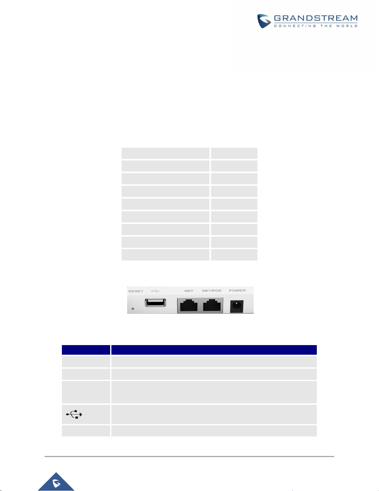
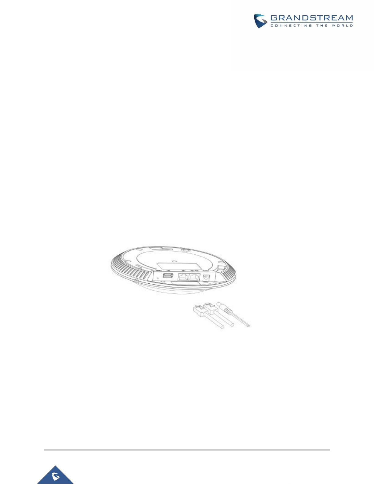
GWN7600 Access Point Ports
Figure 1: GWN7600 Ports
Table 3: GWN7600 Ports Description
Port
Description
Power
Power adapter connector (24V, 1A)
NET/PoE
Ethernet RJ45 port (10/100/1000Mbps) supporting PoE (802.3af).
NET
Ethernet RJ45 port (10/100/1000Mbps) to your router or another
GWN7600 series
USB 2.0 port (for future IOT & location based applications)
RESET
Factory reset button. Press for 7 seconds to reset factory default settings.
Page 17
P a g e | 17
GWN7600 User Manual
Version 1.0.4.12
Power and Connect GWN7600 Access Point
Step 1:
Connect one end of a RJ-45 Ethernet cable into the NET or PoE/NET port of the GWN7600.
Step 2:
Connect the other end of the Ethernet cable(s) into a LAN port to your Network.
Step 3:
Connect the 24V DC power adapter into the power jack on the back of the GWN7600. Insert the main plug
of the power adapter into a surge-protected power outlet.
Note: GWN7600 can be powered using PoE (802.3af) switch via PoE/NET port. In this scenario,
GWN7600 should be connected to the router using NET port.
Step 4:
Wait for the GWN7600 to boot up and acquire an IP address from the DHCP Server.
Figure 2: Connecting GWN7600
Warranty
If the GWN7600 Wireless Access Point was purchased from a reseller, please contact the company where
the device was purchased for replacement, repair or refund. If the device was purchased directly from
Grandstream, contact our Technical Support Team for a RMA (Return Materials Authorization) number
before the product is returned. Grandstream reserves the right to remedy warranty policy without prior
notification.
Page 18
P a g e | 18
GWN7600 User Manual
Version 1.0.4.12
Wall and Ceiling Mount Installation
GWN7600 can be mounted on the wall or ceiling, please refer to the following steps for the appropriate
installation.
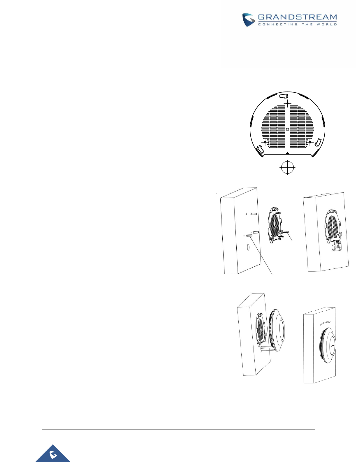
Wall Mount
Step1:
Position the mounting bracket at the desired location on the wall with
the arrow pointing up.
Step 2:
Use a pencil to mark the four mounting holes (screw holes DIA
5.5mm, reticle hole DIA 25mm).
Step 3:
Insert screw anchors into the 5.5 mm holes. Attach the mounting
bracket to the wall by inserting the screws into the anchors.
Step 4:
Connect the power cable and the Ethernet cable (RJ45) to the correct
ports of your GWN7600.
Step 5:
Align the arrow on the GWN7600AP with the arrow on the locking tab
of the mounting bracket and ensure that your GWN is firmly seated
on the mounting bracket.
Step 6:
Turn the GWN clockwise until it locks into place and fits the locking
tab.
Figure 3: Wall Mount – Steps 1 & 2
Figure 4: Wall Mount – Steps 3 & 4
Figure 5: Wall Mount – Steps 5 & 6
PA3.5 x 20 screw
Plastic Expansion Bolt
Page 19
P a g e | 19
GWN7600 User Manual
Version 1.0.4.12
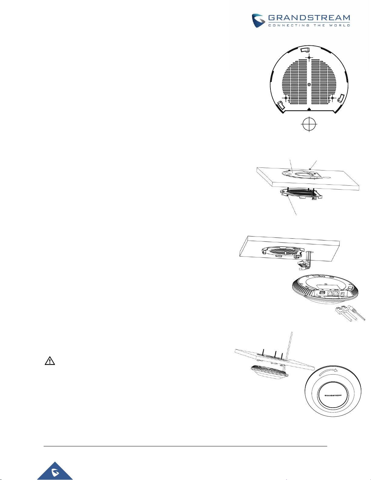
Ceiling Mount
Step 1:
Remove the ceiling tile.
Step 2:
Place the ceiling backing plate in the center of the ceiling tile and
mark the mounting screw holes (screw holes DIA 5.5mm, reticle hole
DIA 25mm).
Step 3:
Insert the screws through the mounting bracket.
Step 4:
Connect the power cable and the Ethernet cable (RJ45) to the correct
ports of your GWN7600.
Step 5:
Align the arrow on the GWN7600AP with the arrow on the locking tab
of the mounting bracket and ensure that your GWN is firmly seated
on the mounting bracket and connect the network and power cables.
Step 6:
Turn the GWN clockwise until it locks into place and fits the locking
tab.
Note:
Ceiling mounting is recommended for optimal coverage performance.
Figure 9: Ceiling Mount – Steps 5 & 6
Figure 6: Ceiling Mount – Steps 1 & 2
Ceiling Mounting Bracket
M3 nut
M3.0x50 screw
Figure 8: Ceiling Mount – Step 4
Figure 7: Ceiling Mount – Step 3
Page 20
P a g e | 20
GWN7600 User Manual
Version 1.0.4.12
GETTING STARTED
The GWN7600 Wireless Access Point provides an intuitive web GUI configuration interface for easy
management to give users access to all the configurations and options for the GWN7600’s setup.
This section provides step-by-step instructions on how to read LED patterns, discover the GWN7600 and
use its Web GUI interface.
LED Patterns
The panel of the GWN7600 has different LED patterns for different activities, to help users read the status
of the GWN7600 whether it’s powered up correctly, provisioned, in upgrading process and more, for more
details please refer to the below table.
Table 4: LED Patterns
LED Status
Indication
OFF
Unit is powered off or abnormal power supply.
Blinking green
Firmware update in progress.
Solid green
Firmware update successful.
Blanking red
Delete slave paring
Solid red
Firmware update failed.
Blinking pink
Unit not provisioned.
Solid pink
Unit not paired
Blinking blue
Unit provisioning in progress.
Solid blue
Unit is provisioned successfully.
Page 21
P a g e | 21
GWN7600 User Manual
Version 1.0.4.12
Discover the GWN7600
Once the GWN7600 is powered up and connected to the Network correctly, users can discover the
GWN7600 using one of the below methods:
Method1: Discover the GWN7600 using its MAC address
1. Locate the MAC address on the MAC tag of the unit, which is on the underside of the device, or on
the package.
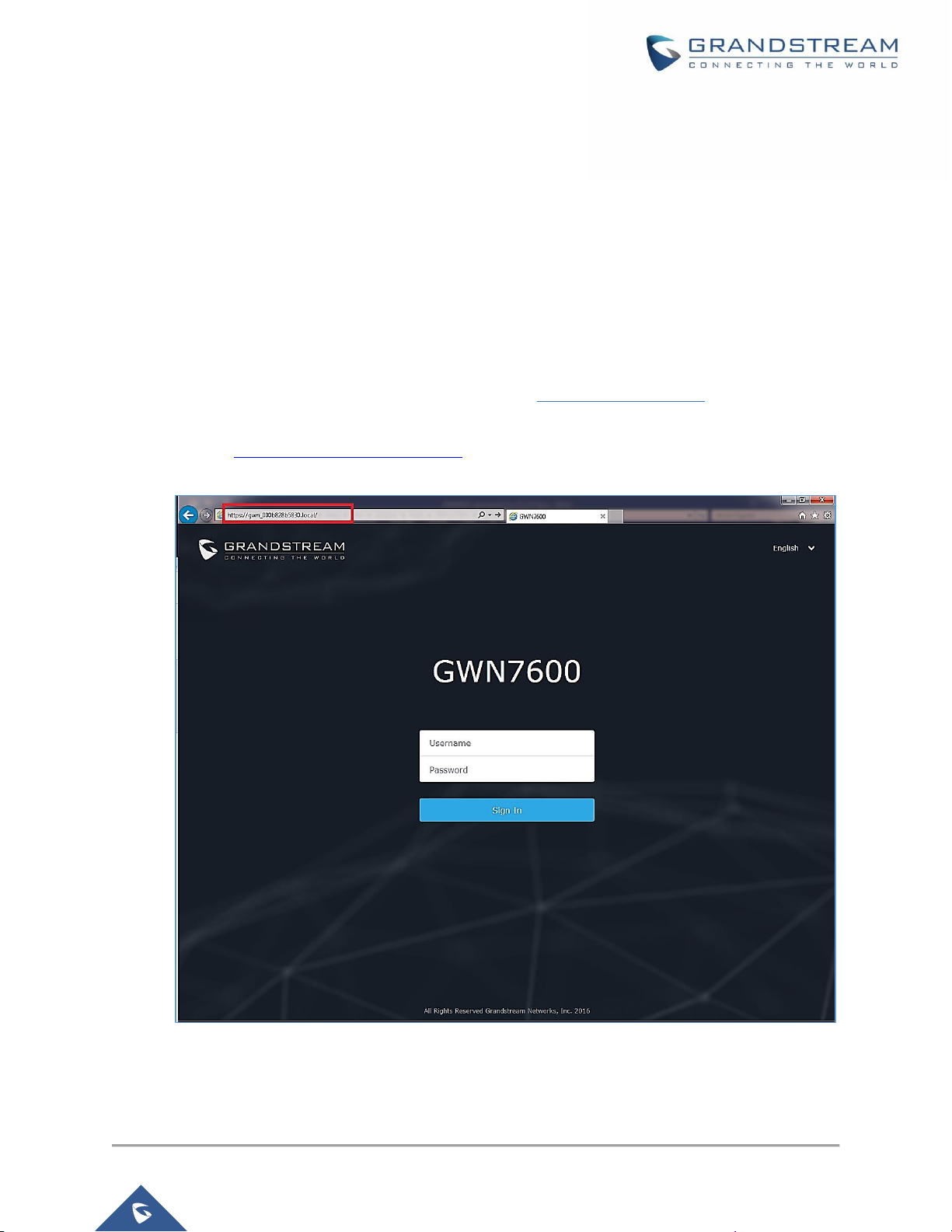
2. From a computer connected to same Network as the GWN7600, type in the following address
using the GWN7600’s MAC address on your browser https://gwn_<mac>.local
For example, if a GWN7600 has the MAC address 00:0B:82:8B:58:30, this unit can be accessed
by typing https://gwn_000b828b5830.local/ on the browser.
Figure 10: Discover the GWN7600 using its MAC Address
Page 22
P a g e | 22
GWN7600 User Manual
Version 1.0.4.12
Method 2: Discover the GWN7600 using GWN Discovery Tool
1. Download and install GWN Discovery Tool from the following link:
http://www.grandstream.com/support/tools
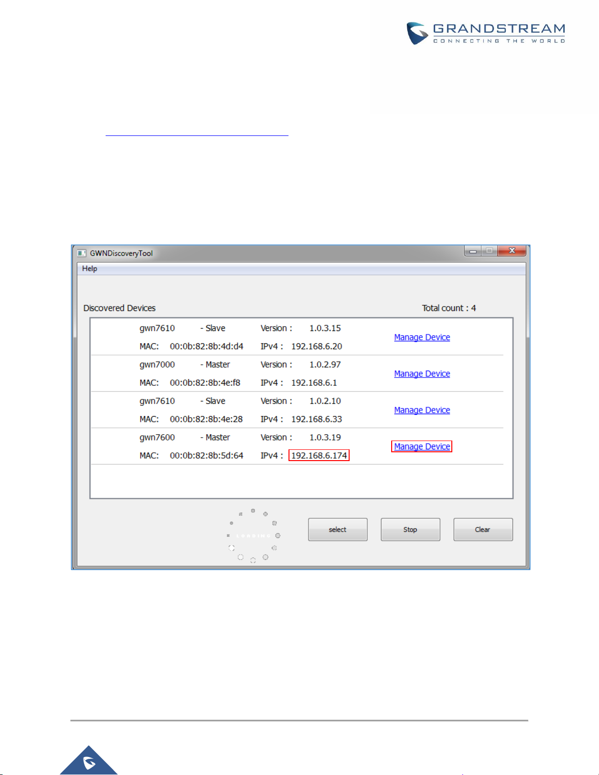
2. Open the GWNDiscoveryTool, click on Select to define the network interface, then click on Scan.
3. The tool will discover all GWN7600 Access Points connected on the network showing their MAC,
IP addresses and firmware version.
4. Click on Manage Device to be redirected directly to the GWN7600's configuration interface, or
type in manually the displayed IP address on your browser.
Figure 11: GWN Discovery Tool
Use the Web GUI
Users can access then the GWN7600 using its WebGUI, the following sections will explain how to access
and use the Web Interface.
Page 23

P a g e | 23
GWN7600 User Manual
Version 1.0.4.12
Access Web GUI
The GWN7600 embedded Web server responds to HTTPS GET/POST requests. Embedded HTML pages
allow users to configure the device through a Web browser such as Microsoft IE, Mozilla Firefox, Google
Chrome and etc.
Figure 12: GWN7600 Web GUI Login Page
To access the Web GUI:
1. Make sure to use a computer connected to the same local Network as the GWN7600.
2. Ensure the device is properly powered up.
3. Open a Web browser on the computer and type in the URL using the MAC address as shown in
Discover the GWN7600 or the IP address using the following format:
https://IP_Address
4. Enter the administrator’s login and password to access the Web Configuration Menu. The default
administrator's username and password are "admin" and "admin".
WEB GUI Languages
Currently the GWN7600 series web GUI supports English and Simplified Chinese.
Users can select the displayed language at the upper right of the web GUI either before or after logging in.
Figure 13: GWN7600 Web GUI Language (Login page)
Page 24

P a g e | 24
GWN7600 User Manual
Version 1.0.4.12
Figure 14: GWN7600 Web GUI Language (Web Interface)
Overview Page
Overview is the first page shown after successful login to the GWN7600’s Web Interface. Overview page
provides an overall view of the GWN7600’s information presented in a Dashboard style for easy
monitoring.
Figure 15: GWN7600's Dashboard
Users can quickly see the status of the GWN7600 for different items, please refer to the following table for
each item:
Table 5: Overview
AP
Shows the number of Access Point that are Discovered, Paired(Online)
and Offline. Users may click on to go to Access Points page for
basic and advanced configuration options for the APs
Page 25

P a g e | 25
GWN7600 User Manual
Version 1.0.4.12
Clients
Shows the total number of connected clients, and a count for clients
connected to each Channel. Users may click on to go to Clients
page for more options.
AP Channel Distribution
Shows the Channel used for all APs that are paired with this Access
Point.
Top AP
Shows the Top APs list, users may assort the list by number of clients
connected to each AP or data usage combining upload and download.
Users may click on to go to Access Points page for basic and
advanced configuration options for the APs.
Top SSID
Shows the Top SSIDs list, users may assort the list by number of clients
connected to each SSID or data usage combining upload and download.
Users may click on to go to Network Group page for more options.
Top Clients
Shows the Top Clients list, users may assort the list of clients by their
upload or download. Users may click on to go to Clients page for
more options.
Alert/Notification
Shows 3 types of Alert/Notifications: Critical, Major and Normal. Users
can click to pop up the list of Alert and Notifications.
Note that Overview page in addition to other tabs can be updated each 15s, 1min ,2min and 5min or Never
by clicking in the upper bar menu (Default is 15s).
Save and Apply Changes
When clicking on "Save" button after configuring or changing any option on the web GUI pages. a
message mentioning the number of changes will appear on the upper menu (See Figure 16).
Click on button to apply changes.
Figure 16: Apply Changes
Page 26

P a g e | 26
GWN7600 User Manual
Version 1.0.4.12
USING GWN7600 AS STANDALONE ACCESS POINT
The GWN7600 can be used in Standalone mode, where it can act as Master Access Point Controller or in
Slave mode and managed by another GWN76xx Master.
This section will describe how to use and configure the GWN7600 in standalone mode.
Connect to GWN7600 Default Wi-Fi Network
GWN7600 can be used as standalone access point out of box, or after factory reset with Wi-Fi enabled by
default.
After powering the GWN7600 and connecting it to the network, GWN7600 will broadcast a default SSID
based on its MAC address GWN [MAC’s last 6 digits] and a random password.
Note that GWN7600’s default SSID and password information are printed on the MAC tag of the unit as
shown on the below figure.
Figure 17: MAC Tag Label
Page 27

P a g e | 27
GWN7600 User Manual
Version 1.0.4.12
Using GWN7600 as Master Access Point Controller
Master Mode allows a GWN7600 to act as an Access Point Controller managing other GWN76XX access
points. This will allow users adding other access points under one controller and managing them in an
easy and a centralized way.
Master/Slave mode is helpful with large installations that needs more coverage area zones with the same
controller.
Figure 18: Login Page
At factory reset, “Set unit as Master” will be checked by default, click on “Sign In” after typing the admin’s
username and password.
Warning:
“Set unit as Master” option will forbid the GWN7600 Access Point from being paired by other Master
GWN76XX, and can only act as a Master Access point controller.
Users will need to perform a factory reset to the GWN7600, or unpair it from the initial GWN76XX in order
to make it open to Master Access Point mode again.
Login Page
After login, users can use the Setup Wizard tool to go through the configuration setup, or exit and configure
it manually. Setup Wizard can be accessed anytime by clicking on while on the web interface.
Page 28

P a g e | 28
GWN7600 User Manual
Version 1.0.4.12
Figure 19: Setup Wizard
Discover and Pair Other GWN7600 Access Point
To Pair a GWN76XX access point connected to the same Network as the GWN7600 follows the below steps:
1. Connect to the GWN7600 Web GUI as Master and go to Access Points.
Figure 20: Discover and Pair GWN7600
2. Click on , in order to discover access points within GWN7600’s Network, the following
page will appear.
Page 29

P a g e | 29
GWN7600 User Manual
Version 1.0.4.12
Figure 21: Discovered Devices
3. Click on Pair under Actions, in order to pair the discovered access point as slave with the
GWN7600 acting as Master.
4. The paired GWN7600 will appear Online, users can click on to unpair it.
Figure 22: GWN7600 Online
5. Users can click on next to Master or paired access point to check device configuration for its
status, users connected to it and configuration. Refer to below table for Device Configuration tabs.
Table 6: Device Configuration
Field
Description
Status
Shows the device’s status information such as MAC, Product Model, Part
Number, Boot Version, Firmware version, IP Address, Link Speed,
Uptime, and Users count via different Radio channels.
Clients
Shows the connected Users to the GWN7600 access point.
Configuration
• Device Name: Set GWN7600’s name to be shown next to MAC
address.
• Fixed IP: Set a static IP for the GWN7600, default is unchecked.
• Frequency: Set the GWN7600’s frequency, it can be either
2.4GHz, 5GHz or Dual-band.
• Band Steering: When Frequency is set to Dual-Band, users can
check this option to enable Band Steering on the Access Point,
this will help redirecting clients to a radio band accordingly for
efficient use and to benefit from the maximum throughput
supported by the client.
Page 30

P a g e | 30
GWN7600 User Manual
Version 1.0.4.12
• Mode: Choose the mode for the frequency band, 802.11n/g/b for
2.4 GHz.
• Channel Width: Choose the Channel Width, note that wide
channel will give better speed/throughput, and narrow channel
will have less interference. 20Mhz is suggested in very
high-density environment.
• 40MHz Channel Location: Configure the 40MHz channel
location when using 20MHz/40MHz in Channel Width, users can
set it to be Secondary below Primary, Primary below Secondary
or Auto.
• Channel: Select Auto, or a specified channel, default is Auto.
Note that the proposed channels depend on Country Settings
under System SettingsMaintenance.
• Enable Short Guard Interval: Check to activate this option to
increase throughput.
• Active Spatial Streams: Choose active spatial stream if Auto, 1
or 2 streams.
• Radio Power: Set the Radio Power, it can be Low, Medium or
High.
• Allow Legacy Devices(802.11b): Check to support 802.11b
devices to connect the AP in 802.11n/g mode.
• Custom Wireless Power(dBm): allows users to set a custom
wireless power for both 5GHz/2.4GHz band, the value of this field
must be between 1 and 31.
Note
If a GWN7600 is not being discovered or the pair icon is grey color, make sure that it is not being paired
with another GWN76XX Access Point acting as Master Controller, if yes users will need to unpair it first, or
reset it to factory default settings in order to make it available for pairing by other GWN76XX Access Point
Controller
AP Location:
GWN supports a handy feature which allows users to locate other Access points by blinking LED. To use
the feature, navigate on the master web GUI under “Access Points” page and click on the icon near
the desired AP, and it corresponding unit will start blinking the LEDs.
Page 31

P a g e | 31
GWN7600 User Manual
Version 1.0.4.12
Failover Master
In a Master-Slave architecture, having a backup Master is critical for redundancy and failover function,
thus, and in order to avoid a single point of failure in your wireless network, you can specify a slave AP as
failover master. Whenever it detects the master is down, it will promote itself as failover master within a
time frame of around 20~30 minutes by entering failover mode. After then, if the master AP comes back,
failover master will automatically go back to slave mode, or if the master doesn’t come back to alive,
Administrator can login using “failover” account to turn the failover master as true master and take over all
controls.
Figure 23: Failover Master
Users could select the failover Master by following below steps:
• Log into web GUI of the master GWN.
• Go to Access Points page.
• Press
• Select from the available paired Slave Aps the candidate to become a failover Master.
• Save and Apply the settings.
Failover Mode
Once failover slave has been selected, the primary master will send the configuration of the network to the
failover slave and the slave will start monitoring the status of the primary master to detect any failure for
any reason (network connection loss, power outage).
In case of failure, the failover slave will promote itself to a temporary backup master while waiting for the
primary master to come back.
During the failover mode users could access the web GUI of the failover slave using a special failover
account with same admin password.
Page 32

P a g e | 32
GWN7600 User Manual
Version 1.0.4.12
• Username = failover
• Password = admin password
Figure 24: Failover Mode GUI
The failover mode has only read permission on the configuration and very limited options, users still can
reboot other slave Access points in case it is needed.
Users also can press on « Switch to master » button in order to set the failover slave as the new primary
master of the wireless network, once this is done they have full write permission control over the web GUI
option as usual.
Client Bridge
The Client Bridge feature allows an access point to be configured as a client for bridging wired only clients
wirelessly to the network. When an access point is configured in this way, it will share the WiFi connection
to the LAN ports transparently. This is not to be confused with a mesh setup. The client will not accept
wireless clients in this mode.
Once a Network Group has an Client Bridge Support enabled, the AP adopted in this Network Group can
be turned in to Bridge Client mode by click the Bridge button .
Please be noted that once an AP it turned into Client Bridge mode, it cannot be controlled by a Master
anymore, and a factory reset is required to turn it back into normal AP mode.
Figure 25: Client Bridge
Important Notes:
• The access point that will be operating on bridge mode, must be set with a fixed IP address before
activating the bridge mode on the access point.
• Users must enable client bridge support option under network group or SSID WiFi settings in order
to have it fully functional. See [Client Bridge Support]
Page 33

P a g e | 33
GWN7600 User Manual
Version 1.0.4.12
NETWORK GROUPS
When using GWN7600 as Master Access Point, users have the ability to create different Network groups
and adding GWN7600 Slave Access Points.
Network Groups
Log in as Master to the GWN7600 WebGUI and go to Network GroupNetwork Group.
Figure 26: Network Group
The GWN7600 will have a default network group named group0, click on to edit it, or click on
to add a new network group.
Page 34

P a g e | 34
GWN7600 User Manual
Version 1.0.4.12
Figure 27: Add a New Network Group
When editing or adding a new network group, users will have four tabs to configure:
• Basic: Used to name the network group, and set a VLAN ID if adding a new network group
Table 7: Basic configuration of group
Field
Description
Network Group Name
Set the name of the new group.
Enabled
Enable the new group.
VLAN
Check to enable/disable VLAN.
VLAN ID
Set a VLAN ID.
Enable IPv4
Check to enable/disable IPv4
IPv4 Static Address
Configure the static address of IPv4
IPv4 Subnet Mask
Configure the corresponding subnet mask of IPv4
DHCP Enabled for IPv4
Check to enable DHCP for IPv4
DHCP Start Address
Set the start address for DHCP
DHCP End Address
Set the end address for DHCP
Page 35

P a g e | 35
GWN7600 User Manual
Version 1.0.4.12
DHCP Leases Time
Set the DHCP lease time for the clients
DHCP Options
Add the Option items for DHCP, detailed option contents can be found
via: https://wiki.openwrt.org/doc/howto/dhcp.dnsmasq
DHCP Gateway
Set the gateway for DHCP, and it is better to set the gateway address out
of the DHCP pool.
DHCP Preferred DNS
Set the preferred DNS for DHCP
DHCP Alternated DNS
Set the alternated DNS for DHCP
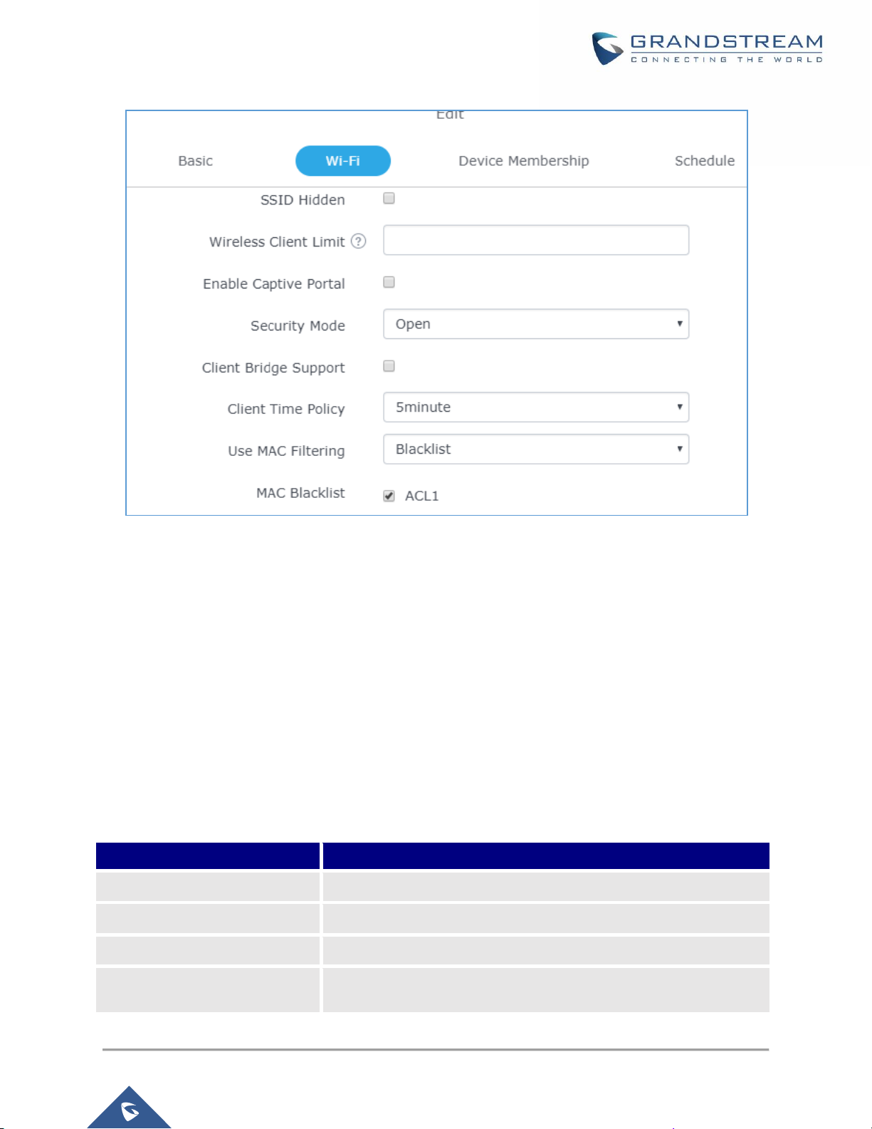
• Wi-Fi: Please refer to the below table for Wi-Fi tab options
Table 8: Wi-Fi
Field
Description
Enable Wi-Fi
Check to enable Wi-Fi for the network group.
SSID
Set or modify the SSID name.
SSID Band
Select the Wi-Fi band the GWN will use, three options are available:
• Dual-Band
• 2.4GHz
• 5Ghz
SSID Hidden
Select to hide SSID. SSID will not be visible when scanning for Wi-Fi, to
connect a device to hidden SSID, users need to specify SSID name and
authentication password manually.
Wireless Client Limit
Configure the limit for wireless client. If there’s an SSID per-radio on a
network group, each SSID will have the same limit. So, setting a limit of
50 will limit each SSID to 50 users independently.
If set to 0 the limit is disabled.
Enable Captive Portal
Click on the checkbox to enable the captive portal feature.
Captive Portal Policy
Select the captive portal policy already created on the “CAPTIVE
PORTAL” web page to be used in the created SSID.
Security Mode
Set the security mode for encryption, 5 options are available:
• WEP 64-bit: Using a static WEP key. The characters can only be
0-9 or A-F with a length of 10, or printable ASCII characters with a
length of 5.
• WEP 128-bit: Using a static WEP key. The characters can only
be 0-9 or A-F with a length of 26, or printable ASCII characters
with a length of 13.
Page 36

P a g e | 36
GWN7600 User Manual
Version 1.0.4.12
• WPA/WPA2: Using “PSK” or “802.1x” as WPA Key Mode, with
“AES” or “AES/TKIP” Encryption Type.
• WPA2: Using “PSK” or “802.1x” as WPA Key Mode, with “AES” or
“AES/TKIP” Encryption Type. Recommended configuration for
authentication.
• Open: No password is required. Users will be connected without
authentication. Not recommended for security reasons.
WPA Key Mode
Two modes are available:
• PSK: Use a pre-shared key to authenticate to the Wi-Fi.
• 802.1X: Use a RADIUS server to authenticate to the Wi-Fi.
WPA Encryption Type
Two modes are available:
• AES: This method changes dynamically the encryption keys
making them nearly impossible to circumvent.
• AES/TKIP: use both Temporal Key Integrity Protocol and
Advanced Encryption Standard for encryption, this provides the
most reliable security.
WPA Pre – Shared Key
Set the access key for the clients, and the input range should be: 8-63
ASCII characters or 8-64 hex characters.
Client Bridge Support
Configures the client bridge support to allows the access point to be
configured as a client for bridging wired only clients wirelessly to the
network. When an access point is configured in this way, it will share the
WiFi connection to the LAN ports transparently. Once a Network Group
has an Client Bridge Support enabled, the AP adopted in this Network
Group can be turned in to Bridge Client mode by click the Bridge button.
Radius Sever Address
Configures Radius authentication server address.
Radius Server Port
Configures Radius Server Listening port (default is: 1812).
Radius Server Secret
Enter the secret password for client authentication with radius server.
Radius Accounting Server
Configures the address for the radius accounting server.
Radius Accounting Server
Port
Configures Radius accounting server listening port (defaults to 1813).
Radius Accounting Server
Secret
Enter the secret password for client authentication with radius accounting
server.
Page 37

P a g e | 37
GWN7600 User Manual
Version 1.0.4.12
Use MAC Filtering
Choose Blacklist/Whitelist to specify MAC addresses to be
excluded/included from connecting to the zone’s Wi-Fi. Default is
Disabled.
Enable Dynamic VLAN
When enabled, clients will be assigned IP address form corresponding
VLAN configured on the Radius user profile.
Client Isolation
Client isolation feature blocks any TCP/IP connection between connected
clients to GWN7600’s Wi-Fi access point. Client isolation can be helpful to
increase security for Guest networks/Public Wi-Fi.
Three modes are available:
• Internet Mode: Wireless clients will be allowed to access only the
internet services and they cannot access any of the management
services, either on the router nor the access points GWN7600.
• Gateway MAC Mode: Wireless clients can only communicate with
the gateway, the communication between clients is blocked and
they cannot access any of the management services on the
GWN7600 access points.
• Radio Mode: Wireless clients can access to the internet
services, GWN7xxx router and the access points GWN7600 but
they cannot communicate with each other.
Gateway MAC Address
This field is required when using Client Isolation, so users will not lose
access to the Network (usually Internet).
Type in the default LAN Gateway’s MAC address (router’s MAC address
for instance) in hexadecimal separated by “:”.
Example: 00:0B:82:8B:4D:D8
RSSI Enabled
Check to enable RSSI function, this will lead the AP to disconnect users
below the configured threshold in Minimum RSSI (dBm).
Minimum RSSI (dBm)
Enter the minimum RSSI value in dBm. If the signal value is lower than
the configured minimum value, the client will be disconnected. The input
range is from “-94” or “-1”.
Enable Voice Enterprise
Check to enable/disable Voice Enterprise. The roaming time will be
reduced once enable voice enterprise.
• The 802.11k standard helps clients to speed up the search for
nearby APs that are available as roaming targets by creating an
optimized list of channels. When the signal strength of the current
AP weakens, your device will scan for target APs from this list.
Page 38

P a g e | 38
GWN7600 User Manual
Version 1.0.4.12
• When your client device roams from one AP to another on the
same network, 802.11r uses a feature called Fast Basic Service
Set Transition (FT) to authenticate more quickly. FT works with
both pre-shared key (PSK) and 802.1X authentication methods.
• 802.11v allows client devices to exchange information about the
network topology, including information about the RF
environment, making each client network aware, facilitating
overall improvement of the wireless network.
Note: 11R is required for enterprise audio feature, 11V and 11K are
optional.
Enable 11R
Check to enable 802.11r
Enable 11K
Check to enable 802.11k
Enable 11V
Check to enable 802.11v
Upstream Rate
Set the maximum upstream rate
Downstream Rate
Set the maximum downstream rate
• Device Membership: Used to add or remove paired access points to the network group.
Figure 28: Device Membership
Page 39

P a g e | 39
GWN7600 User Manual
Version 1.0.4.12
Click on to add the GWN7600 to the network group, or click on to remove it.
Users can Also add a device to a Network Group from Access Points Page:
Figure 29: WiFi Schedule
If users want to schedule the AP operation time, “Enable Wireless Schedule” should be selected first, and
then, choose the days the AP needs to work, at last, click on “Save” to save configuration.
- Select the desired AP to add to a Network Group and click on
Page 40

P a g e | 40
GWN7600 User Manual
Version 1.0.4.12
Figure 30: Add AP to Network Group
Create an Additional SSID under same Network Group
Users can also create an additional SSID under the same group.
To create an additional SSID go to Network GroupAdditional SSID.
Figure 31: Additional SSID
Page 41

P a g e | 41
GWN7600 User Manual
Version 1.0.4.12
Select one of the available network groups from Network Group Membership dropdown menu, this will
create an additional SSID with the same Device Membership configured when creating the main network
group.
Figure 32: Additional SSID Created
Click on to delete the additional SSID, or to edit it.
Page 42

P a g e | 42
GWN7600 User Manual
Version 1.0.4.12
CLIENTS CONFIGURATION
Users can configure clients’ parameters, time policy and also check the list of the clients that has been
banned after time disconnect policy has been enabled. Below we discuss each section of this menu:
Clients
Users can access clients list connected to GWN7600 from Web GUIClientsClients to perform
different actions to wireless clients.
Figure 33: Clients
• Click on under Actions to check client’s status and modify basic settings such Device’s Name.
• Click on to block a client’s MAC address from connecting to the zone’s network group.
Clients Access
From this menu, users can manage in global way the blacklist of clients that will be blocked from accessing
the WiFi network, click on to add or remove MAC addresses of client from global
blacklist.
Page 43

P a g e | 43
GWN7600 User Manual
Version 1.0.4.12
Figure 34: Global Blacklist
Figure 35: Managing the Global Blacklist
A second option, is to add custom access lists that will be used as matching mechanism for MAC address
filtering option under network groups and SSIDs to allow (whitelist) or disallow (blacklist) clients access to
the WiFi network.
Click on in order to create new access list, then fill it with all MAC addresses to be matched.
Figure 36: Adding New Access List
Once this is done, this access list can be used under network group or SSID WiFi settings to filter clients
either using whitelist or blacklist mode.
Page 44
P a g e | 44
GWN7600 User Manual
Version 1.0.4.12
Figure 37: Blacklist Access List
Time Policy
The timed client disconnect feature allows the system administrator to set a fixed time for which clients
should be allowed to connect to the access point, after which the client will no longer be allowed to connect
for a user configurable cool-down period.
The configuration is based on a policy where the administrator can set the amount of time for which clients
are allowed to connect to the WiFi and reconnect type and value after which they will be allowed to
connect back after they have been disconnected.
In order to create a new policy, go under ClientsTime Policy and add new one., then the following
parameters:
Table 9: Time Policy Parameters
Option
Description
Name
Enter the name of the policy
Enabled
Check the box to enable the policy
Limit Client Connection Time
Sets amount of time a client may be connected.
Client Reconnect Timeout Type
Select the method with which we will reset a client’s connection timer
so they may reconnect again. Options are:
Page 45
P a g e | 45
GWN7600 User Manual
Version 1.0.4.12
• Reset Daily.
• Reset Weekly.
• Reset Hourly.
• Timed Reset.
Client Reconnect Timeout
If “Timed Reset” is selected, this is the period for which the client will
have to wait before reconnecting.
Reset Day
If “Reset Weekly” is selected, this is the day when the reset will be
applied.
Reset Hour
If “Reset Weekly” or “Reset Daily” is selected, this is the hour and day
when the reset will be applied.
Note: Time tracking shall be accounted for on a per-policy basis, such that a client connected to any SSID
assigned the time tracking policy will accrue a common counter, regardless of which SSID they are
connected to (as long as those SSIDs all share the same time tracking policy).
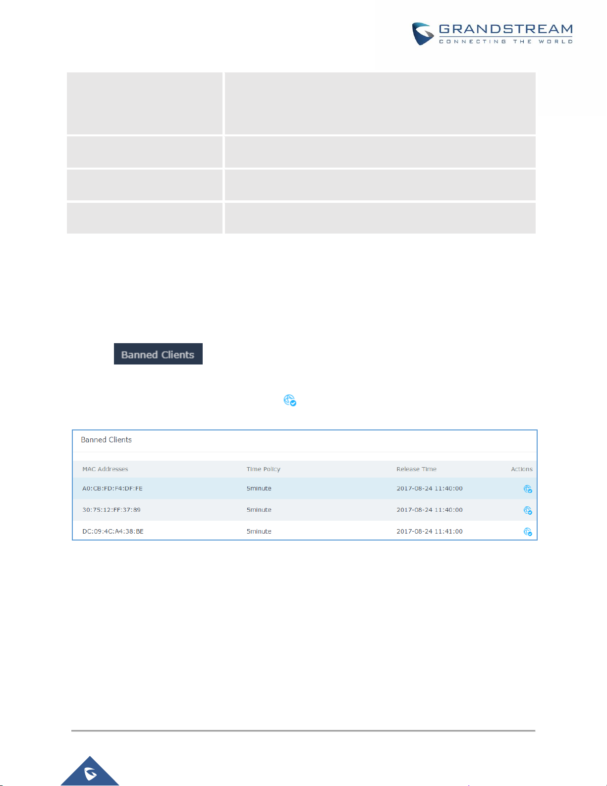
Banned Clients
Click on menu to view the list of the clients that have been banned after time
disconnect feature has taken effect, these clients will not be allowed to connect back until timeout reset or
you can unblock a client by clicking on the icon .
Figure 38: Ban/Unban Client
Page 46

P a g e | 46
GWN7600 User Manual
Version 1.0.4.12
LED SCHEDULE
GWN7600 Access Points series support also the LED schedule feature. This feature is used to set the
timing when the LEDs are ON and when they will go OFF at customer’s convenience.
This can be useful for example when the LEDs become disturbing during some periods of the day, this way
with the LED scheduler, you can set the timing so that the LEDs are off at night after specific hours and
maintain the Wi-Fi service for other clients without shutting down the AP.
To configure LED schedule, on the GWN7600 WebGUI navigate to “System SettingsLEDs”.
Following options are available:
Table 10: LEDs
Field
Description
LEDs Always Off
Configure whether to disable the AP LED dictator
Schedule Stop Hour
Configure the hour the AP LED dictator is disabled. The valid range is from
0 to 23. And the value cannot be empty.
Schedule Start Hour
Configure the minute the AP LED dictator is disabled. The valid range is
from 0 to 59.
Schedule Stop Minute
Configure the hour the AP LED dictator is enabled. The valid range is from
0 to 23. And the value cannot be empty.
Schedule Start Minute
Configure the minute the AP LED dictator is enabled. The valid range is
from 0 to 59.
Schedule Weekdays list
of schedule days
Select the days the AP LED is desired to be disabled or enabled.
Following example on the next page sets the LEDs to be turned on from 8am till 8pm every day.
Page 47

P a g e | 47
GWN7600 User Manual
Version 1.0.4.12
Figure 39: LED Scheduling Sample
Page 48

P a g e | 48
GWN7600 User Manual
Version 1.0.4.12
CAPTIVE PORTAL
Captive Portal feature on GWN7600 AP helps to define a Landing Page (Web page) that will be displayed
on Wi-Fi clients’ browsers when attempting to access Internet. Once connected to a GWN7600 AP, Wi-Fi
clients will be forced to view and interact with that landing page before Internet access is granted.
The Captive Portal feature can be configured from the GWN7600 Web page under “Captive Portal”.
The page contains three tabs: Policy, Files and Clients.
Policy
Users can customize a portal policy in this page.
Figure 40: Captive Portal Policy
Click on to edit the policy.
Click on to delete the policy.
Click on to add a policy.
Page 49

P a g e | 49
GWN7600 User Manual
Version 1.0.4.12
Figure 41: Add a New Policy
Below table lists the items policy add page configures.
Table 11: Policy Parameters
Field
Description
Name
Enter the name of the Captive Portal policy
Expiration
Configures the period of validity, after the valid period, the client will be
re-authenticated again.
Authentication Type
Three types of authentication are available:
• No Authentication: when choosing this option, the landing page feature
will not provide any type of authentication, instead it will prompt users to
accept the license agreement to gain access to internet.
• RADIUS Server: Choosing this option will allow users to set a RADIUS
server to authenticate connecting clients.
• Third Authentication: Choosing this option will allow users to enable
authentication Facebook or WeChat.
Radius Server Address
Fill in the IP address of the radius server.
Radius Server Port
Set the radius server port, the default value is 1812.
Page 50

P a g e | 50
GWN7600 User Manual
Version 1.0.4.12
Radius Server Key
Fill in the key of the radius server.
Radius Authentication
Method
Select the radius authentication method, 3 methods are available: PAP, CHAP
and MS-CHAP.
WeChat Authentication
Check to enable/disable WeChat Authentication
Shop ID
Fill in the Shop ID that offers WeChat Authentication.
APP ID
Fill in the APP ID provided by the WeChat in its web registration page
SecretKey
Set the key for the portal, once clients want to connect to the WiFi, they should
enter this key.
Facebook
Authentication
Check to enable/disable Facebook Authentication
Facebook App ID
Fill in the Facebook App ID.
Facebook APP Key
Set the key for the portal, once clients want to connect to the WiFi, they should
enter this key.
Portal Page
Customization
Select the customized portal page.
Landing Page
Choose the landing page, 2 options are available: redirect to the origin and
redirect to external page.
Redirect External Page
URL Address
Once the landing page is set to redirect to external page, user should set the
URL address for redirecting.
Enable HTTPS
Check to enable/disable HTTPS service.
Pre-Authentication
Rule(s)
Set the Pre-Authentication Rules for temporarily release the IP or ports of the
devices (e.g.: subnet:192.168.10.1/12, TCP: TCP src 80 dst 80, UDP: UDP src
80 dst 80, SSH, telnet)
Post Authentication
Rule(s)
Set the Post Authentication Rules (e.g.: subnet:192.168.10.1/12, TCP: TCP src
80 dst 80, UDP: UDP src 80 dst 80, SSH, telnet, http, https)
Files
Files configuration page allows users to view and upload HTML pages and related files (images…).
The captive portal uses two HTML pages using authentication scenarios, either portal_default.html which
doesn’t provide authentication, only accepting license agreement, while portal_pass.html provides
textboxes for authentication, Wired or Wi-Fi clients will be redirected to one of these pages before
accessing Internet. The following figure shows portal_default.html page:
Page 51

P a g e | 51
GWN7600 User Manual
Version 1.0.4.12
Figure 42: Captive Portal Files
User can add folder in corresponding folder by selecting the folder and click on .
Click on to upload a file from local device.
Click on to download the files in Captive Portal folder.
Click on to edit the corresponding file, in another word, to replace the file with a new one.
Click on to delete the file.
Page 52

P a g e | 52
GWN7600 User Manual
Version 1.0.4.12
Clients
This section lists the clients connected or trying to connect to Wi-Fi.
Figure 43: Captive Portal Clients
Page 53

P a g e | 53
GWN7600 User Manual
Version 1.0.4.12
BANDWIDTH RULES
The bandwidth rule is a GWN7600 feature that allows users to limit bandwidth utilization per SSID or client
(MAC address or IP address).
This option can be configured from the GWN7600 WebGUI under “Bandwidth Rules”.
Click to add a new rule, the following table provides an explanation about different options
for bandwidth rules.
Table 12: Bandwidth Rules
Field
Description
Type
Choose the type of rule to be applied on bandwidth utilization from the
dropdown list, three options are available:
• SSID: Set a bandwidth limitation on the SSID level.
• MAC: Set a bandwidth limitation per MAC address.
• IP Address: Set a bandwidth limitation per IP address.
SSID
Select the SSID to which the limitation will be applied, this option
appears only when SSID type is selected.
MAC
Enter the MAC address of the device to which the limitation will be
applied, this option appears only when MAC type is selected.
IP address
Enter the IP address of the device to which the limitation will be
applied, this option appears only when IP Address type is selected.
Network Group
Choose the network group to which belongs the device, this option is
available when choosing either MAC or IP address type.
Upstream Rate
Specify the limit for the upload bandwidth using Kbps or Mbps.
Downstream Rate
Specify the limit for the download bandwidth using Kbps or Mbps.
The following figure shows an example of MAC address rule limitation.
Page 54

P a g e | 54
GWN7600 User Manual
Version 1.0.4.12
Figure 44: MAC Address Bandwidth Rule
The following figure shows examples of bandwidth rules:
Figure 45: Bandwidth Rules
Note:
The same settings for bandwidth management are available from the following menus:
Per-SSID
Navigate on the web GUI under “Network GroupAdd /EditWiFi” and you can set the Upstream and
Downstream rate in Mbps.
Per-Client
Navigate on the web GUI under “ClientsEditBandwidth Rules” where you can set the Upstream and
Downstream rate in Mbps
Page 55

P a g e | 55
GWN7600 User Manual
Version 1.0.4.12
SYSTEM SETTINGS
Maintenance
Users can access Maintenance page from GWN7600 WebGUISystem Settings Maintenance.
Basic
Basic page allows Country and Time configuration.
Table 13: Basic
Field
Description
Web HTTP Access
Enables Web HTTP Access. By default, it’s disabled.
Web HTTPS Port
Specifies HTTPS port. By default, is 443.
Country
Select the country from the drop-down list. This can affect the number of
channels depending on the country standards.
Time Zone
Configure time zone for the GWN7600.
Make sure to reboot the device to take effect.
NTP Server
Configure the IP address or URL of the NTP server. The device will obtain
the date and time from the configured server.
Date Display Format
Change the Date Display Format, three options are possible YYYY/MM/DD,
MM/DD/YYYY and DD/MM/YYYY
Upgrade
The Upgrade Web page allows upgrade related configuration.
Table 14: Upgrade
Field
Description
Authenticate Config File
Authenticate configuration file before acceptance. Default is disabled.
XML Config File Password
Enter the password for encrypting the XML configuration file using
OpenSSL. The password is used to decrypt the XML configuration file if it is
encrypted via OpenSSL.
Upgrade Via
Specify uploading method for firmware and configuration. 3 options are
available: HTTP, HTTPS and TFTP.
Firmware Server
Configure the IP address or URL for the firmware upgrade server.
Config Server
Configure the IP address or URL for the configuration file server.
Check/Download New
Firmware at Boot
Choose whether to enable or disable automatic upgrade and provisioning
after reboot. Default is disabled.
Allow DHCP options 66
Configure whether to allow DHCP options 66 and 63 to override the upgrade
Page 56

P a g e | 56
GWN7600 User Manual
Version 1.0.4.12
and 43 override
and provisioning setting.
Automatic Upgrade(m)
Specify the time to check for firmware upgrade (in minutes).
Reboot
Click on Reboot button to reboot the device.
Download Configuration
Click on Download to download the device’s configuration file.
Upload Configuration
Click on Upload to upload the device’s configuration file.
Upgrade Now
Click on Upgrade, to launch firmware/config file provisioning.
Please make sure to Save and Apply changes before clicking on Upgrade.
Factory Reset
Click on Reset to restore the GWN7600 to factory default settings
Access
The Access Web page provide configuration for admin and user password.
Table 15: Access
Field
Description
Current Administrator
Password
Enter the current administrator password
New Administrator
Password
Change the current password. This field is case sensitive with a maximum
length of 32 characters.
Confirm New
Administrator Password
Enter the new administrator password one more time to confirm.
New User Password
Configure the password for user-level Web GUI access. This field is case
sensitive with a maximum length of 32 characters.
Confirm New User
Password
Enter the new User password again to confirm.
Syslog
The syslog Web page provides configuration settings for syslog.
Page 57

P a g e | 57
GWN7600 User Manual
Version 1.0.4.12
Figure 46: Syslog Server Page
Table 16: Syslog Parameters
Field
Description
Syslog Server
Enter the IP address or URL of Syslog server.
Syslog Level
Select the level of Syslog, 5 levels are available: None, Debug, Info,
Warning and Error.
Logserver
The logserver page allows the user to configure syslog server on GWN7600 in order to save log messages
on connected external USB drive.
First connect a USB drive to the Access point, then configure the parameters and make sure to start the
server in order to collect messages from devices sending syslog to GWN.
Figure 47: Logserver
Page 58

P a g e | 58
GWN7600 User Manual
Version 1.0.4.12
Following table gives description for configuration parameters of GWN Logserver:
Option
Description
Logrotate File Size
Select the size of file to trigger rotation, if left empty, then the router will
use only the Logrotate frequency rules to trigger rotation.
Default is 5 M. Units can be M (Megabytes) or K (Kilobytes).
Logrotate File Count
Select the Maximum number of rotates files to keep. Default is 56 files.
Logrotate Mode
Choose the time rotation frequency mode (default every 3 hours).
• Every X Minutes (0-59).
• Every X hours (0-23)
• X hour of day (0-23).
• X day of week (Sunday-Saturday) + X hour of day (0-23).
Hours
Enter the number of hours period after which trigger file rotation.
Minutes
Enter the number of Minutes period after which trigger file rotation.
Hour of the day
Enter the hour of day at which trigger file rotation.
Day of the week
Enter Day of the week + hour of day, at which trigger file rotation.
Devices
Select the path (a USB partition) to store collected logs. Required.
Enable Logserver
Enables the logserver.
After settings up the logserver and saving the settings, users need to connect an USB external storage
and press Start button in order to start collecting logs.
All log messages from all devices will be put on one single file, and the router will keep rotating and
creating new files based on the configured rotation policy.
• Under Syslog File List, users can select a device and press List button to list all saved logs on
this device.
• Press Download button to download a saved log.
• Press Clear button to remove logs.
Page 59

P a g e | 59
GWN7600 User Manual
Version 1.0.4.12
Debug
GWN7600 offers many features for managing and monitoring connected clients to network groups, as well
as debugging and troubleshooting
Capture
This section is used to generate packet trace captures from network groups interfaces which will help to
sniff packets within the network group for troubleshooting purpose or monitoring. Users will need to plug a
USB device to the USB port on the back of the GWN7600.
To access Capture page, go to System SettingsDebugCapture.
Figure 48: Capture Page
The below table will show different fields used on debug page
Page 60

P a g e | 60
GWN7600 User Manual
Version 1.0.4.12
Table 17: Debug
Required Options
File Name
Enter the name of the capture file that will be generated.
Interface
Choose a network group as Interface on which the traffic will be captured.
Device
Choose a device plugged to USB port to save the capture once started.
Advanced Options
File Size
Set a File size that the capture will not exceed.
Rotate Count
Set a value for rotating captures.
Direction
Choose if you want to get all traffic or only outgoing or incoming to the chosen
interface.
Filtering Options
Source Port
Set the Source Port to filter capture traffic coming from the defined source port.
Destination Port
Set the Destination Port to filter capture traffic coming from the defined port.
Source IP
Set the Source IP to filter capture traffic coming from the defined source IP.
Dest IP
Set the Destination IP to filter capture traffic coming from the defined destination
IP.
Protocol
Choose ALL or a specific protocol to capture (IP, ARP, RARP, TCP, UDP, ICMP,
IPv6)
Click on to start capturing on a certain device plugged to the USB port.
Click on to stop the capture.
Click on to show the captured files on a chosen device, users could check the capture files
details.
Click on to delete all files.
Click on next to a capture file to download it on a local folder.
Click on to delete the corresponding capture file.
Page 61

P a g e | 61
GWN7600 User Manual
Version 1.0.4.12
Figure 49: Capture Files
Core Files
The Core Files Web page displays core dumps generated when the GWN7600 crashes. This is helpful for
troubleshooting purposes, if any core dump found on this page please help to contact our support team for
further investigation using following link: https://helpdesk.grandstream.com/
Ping/Traceroute
Ping and Traceroute are useful debugging tools to verify reachability with other clients across the network.
The GWN7600 offers both Ping and Traceroute tools for IPv4 and IPv6 protocols.
To use these tools, go to GWN7600 WebGUISystem SettingsDebugPing/Traceroute.
Page 62

P a g e | 62
GWN7600 User Manual
Version 1.0.4.12
Figure 50: IP Ping
• Next to Tool choose from the dropdown menu: - IPv4 Ping for an IPv4 Ping test to Target
- IPv6 Ping for an IPv6 Ping test to Target
- IPv4 Traceroute for an IPv4 Traceroute to Target
- IPv6 Traceroute for an IPv6 Traceroute to Target
• Type in the destination’s IP address in Target field.
• Click on Run.
Figure 51: IP Traceroute
Syslog
The syslog Web page displays logs generated by the GWN7600 for troubleshooting purpose as shown in
figure below.
Syslog messages are also displayed in real time under Web GUISystem SettingsDebugSyslog.
Page 63

P a g e | 63
GWN7600 User Manual
Version 1.0.4.12
Figure 52: Syslog
Email/Notification
The Email/Notification page allows the administrator to select a predefined set of system events and to
send notifications upon the change of the set events.
Note:
A reboot is required in order to activate email notification feature.
Page 64

P a g e | 64
GWN7600 User Manual
Version 1.0.4.12
Figure 53: Email
Table 18: Email Setting
Filed
Description
Enabled
Enable/disable the email settings. By default, it’s disabled
Host
Configures the SMTP Email Server IP or Domain Name.
Port
Specifies the Port number used by server to send email.
Username
Specifies sender’s User ID or account ID in the email system used.
Password
Specifies sender’s password of the email account.
Email Address
Specifies the email address of the administer where to receive notifications.
Page 65

P a g e | 65
GWN7600 User Manual
Version 1.0.4.12
Figure 54: Notification
The following table describes the notifications configuration settings.
Table 19: Email Events
Filed
Description
Enabled
Enable/disable the notification. By default, it’s disabled
Memory Usage
Configures whether to send notification if memory usage is greater than the
configured threshold. By default, it’s disabled.
Memory Usage
Threshold (%)
Specifies the Memory Usage Threshold (%). Must be integer between 1 and 100.
CPU Usage
Configures whether to send notification if CPU usage is greater than the
configured threshold. By default, it’s disabled.
Page 66

P a g e | 66
GWN7600 User Manual
Version 1.0.4.12
CPU Usage
Threshold (%)
Specifies the CPU Usage Threshold (%). Must be integer between 1 and 100.
Firmware upgrade
Configures whether to send notification on firmware upgrade. Default is disabled.
Add/Remove
Network Group
Configures whether to send notification when network groups has been
added/removed.
Additional SSID
Configures whether to send notification if any additional SSID is enabled. Default
is disabled.
Time Zone Change
Configures whether to send notification on time zone change. Default is disabled.
Administrator
Password Change
Configures whether to send notification on admin password change. Default is
disabled.
AP Offline
Configures whether to send notification when AP going offline. Default is disabled.
Page 67

P a g e | 67
GWN7600 User Manual
Version 1.0.4.12
UPGRADING AND PROVISIONING
Upgrading Firmware
The GWN7600 can be upgraded to a new firmware version remotely or locally. This section describes how
to upgrade your GWN7600.
Upgrading via WEB GUI
The GWN7600 can be upgraded via TFTP/HTTP/HTTPS by configuring the URL/IP Address for the
TFTP/HTTP/HTTPS server and selecting a download method. Configure a valid URL for TFTP, HTTP or
HTTPS; the server name can be FQDN or IP address.
Examples of valid URLs:
firmware.grandstream.com/BETA
192.168.5.87
The upgrading configuration can be accessed via Web GUISystem SettingsMaintenance.
Table 20: Network Upgrade Configuration
Field
Description
Upgrade Via
Allow users to choose the firmware upgrade method: TFTP, HTTP
or HTTPS.
Firmware Server
Define the server path for the firmware server.
Check Update on Boot
Allows the device to check if there is a firmware from the
configured firmware server at boot.
Automatic Upgrade check
interval(m)
Set the value for automatic upgrade check in minutes.
Upgrade Now
Click on button to begin the upgrade. Note that the
device will reboot after downloading the firmware.
Upgrading Slave Access Points
When the GWN7600 is being paired as slave using another GWN7600 Access Point acting as Controller,
users can upgrade their paired access points from the GWN7600 Master Controller.
Page 68

P a g e | 68
GWN7600 User Manual
Version 1.0.4.12
To upgrade a slave access point, log in to the GWN7600 acting as Master Controller and go to Access
Points.
Figure 55: Access Points
Make sure that firmware server path is set correctly under Maintenance, check the desired APs to upgrade,
and click on to upgrade the selected paired access points.
The status of the device will show Upgrading, wait until it finishes and reboots, then it will appear online
again.
--------------------------------------------------------------------------------------------------------------------------------------------
Notes:
• Please do not interrupt or power cycle the GWN7600 during upgrading process.
• The Master Access Point needs to be upgraded from Web GUISystem
SettingsMaintenance. It cannot be upgraded from Access Points page like the Paired Access
Points.
--------------------------------------------------------------------------------------------------------------------------------------------
Service providers should maintain their own firmware upgrade servers. For users who do not have
TFTP/HTTP/HTTPS server, some free windows version TFTP servers are available for download from
http://www.solarwinds.com/products/freetools/free_tftp_server.aspx
http://tftpd32.jounin.net
Please check our website at http://www.grandstream.com/support/firmware for latest firmware.
Page 69

P a g e | 69
GWN7600 User Manual
Version 1.0.4.12
Instructions for local firmware upgrade via TFTP:
1. Unzip the firmware files and put all of them in the root directory of the TFTP server;
2. Connect the PC running the TFTP server and the GWN7600 to the same LAN segment;
3. Launch the TFTP server and go to the File menuConfigureSecurity to change the TFTP server's
default setting from "Receive Only" to "Transmit Only" for the firmware upgrade;
4. Start the TFTP server and configure the TFTP server in the GWN7600 web configuration interface;
5. Configure the Firmware Server to the IP address of the PC;
6. Update the changes and reboot the GWN7600.
End users can also choose to download a free HTTP server from http://httpd.apache.org/ or use
Microsoft IIS web server.
Provisioning and Backup
The GWN7600 configuration can be backed up locally or via network. The backup file will be used to
restore the configuration on GWN7600 when necessary.
Download Configuration
Users can download the GWN7600 configuration for restore purpose under Web GUISystem
SettingsMaintenanceUpgrade.
Click on to download locally the configuration file.
Upload Configuration
Users can upload configuration file to the GWN7600 under Web GUISystem
SettingsMaintenanceUpgrade.
Click on to browse for the configuration to upload.
Please note that the GWN7600 will reboot after the configuration file is restored successfully.
Configuration Server (Pending)
Users can download and provision the GWN7600 by putting the config file on a TFTP/HTTP or HTTPS
server, and set Config Server to the TFTP/HTTP or HTTPS server used in order for the GWN7600 to be
provisioned with that config server file.
Page 70

P a g e | 70
GWN7600 User Manual
Version 1.0.4.12
Reset and reboot
Users could perform a reboot and reset the device to factory functions under Web GUISystem
SettingsMaintenanceUpgrade by clicking on button.
Will restore all the GWN7600 itself to factory settings.
Syslog
On the GWN7600, users could dump the syslog information to a remote server under Web GUISystem
SettingsMaintenance. Enter the syslog server hostname or IP address and select the level for the
syslog information. Five levels of syslog are available: None, Debug, Info, Warning, and Error.
Page 71

P a g e | 71
GWN7600 User Manual
Version 1.0.4.12
EXPERIENCING THE GWN7600 WIRELESS ACCESS POINT
Please visit our website: http://www.grandstream.com to receive the most up- to-date updates on firmware
releases, additional features, FAQs, documentation and news on new products.
We encourage you to browse our product related documentation, FAQs and User and Developer Forum
for answers to your general questions. If you have purchased our products through a Grandstream
Certified Partner or Reseller, please contact them directly for immediate support.
Our technical support staff is trained and ready to answer all of your questions. Contact a technical support
member or submit a trouble ticket online to receive in-depth support.
Thank you again for purchasing Grandstream GWN7600 Wireless Access Point, it will be sure to bring
convenience and color to both your business and personal life
 Loading...