

Page 1
Grandstream Networks, Inc.
GWN7000
Enterprise Multi-WAN Gigabit VPN Router
User Manual
Page 2

P a g e | 2
GWN7000 User Manual
Version 1.0.4.23
COPYRIGHT
©2017 Grandstream Networks, Inc. http://www.grandstream.com
All rights reserved. Information in this document is subject to change without notice. Reproduction or
transmittal of the entire or any part, in any form or by any means, electronic or print, for any purpose without
the express written permission of Grandstream Networks, Inc. is not permitted.
The latest electronic version of this guide is available for download here:
http://www.grandstream.com/support
Grandstream is a registered trademark and Grandstream logo is trademark of Grandstream Networks, Inc.
in the United States, Europe and other countries.
OPEN SOURCE LICENSES
GWN7000 firmware contains third-party open source software. Grandstream Open source licenses can be
downloaded from Grandstream web site from here
CAUTION
Changes or modifications to this product not expressly approved by Grandstream, or operation of this
product in any way other than as detailed by this guide, could void your manufacturer warranty.
WARNING
Please do not use a different power adaptor with devices as it may cause damage to the products and
void the manufacturer warranty.
Page 3

P a g e | 3
GWN7000 User Manual
Version 1.0.4.23
Table of Contents
DOCUMENT PURPOSE ............................................................................................... 10
CHANGE LOG .............................................................................................................. 11
Firmware Version 1.0.4.23 ................................................................................................................... 11
Firmware Version 1.0.4.20 ................................................................................................................... 11
Firmware Version 1.0.2.75 ................................................................................................................... 11
Firmware Version 1.0.2.71 ................................................................................................................... 12
WELCOME ................................................................................................................... 13
PRODUCT OVERVIEW ................................................................................................ 14
Technical Specifications ....................................................................................................................... 14
INSTALLATION ............................................................................................................ 16
Equipment Packaging .......................................................................................................................... 16
Connect your GWN7000 ...................................................................................................................... 16
Safety Compliances ............................................................................................................................. 17
Warranty ............................................................................................................................................... 17
GETTING STARTED ..................................................................................................... 18
LED Indicators ..................................................................................................................................... 18
Use the WEB GUI ................................................................................................................................ 18
Access WEB GUI .......................................................................................................................... 18
WEB GUI Languages ................................................................................................................... 20
WEB GUI Configuration ................................................................................................................ 21
Overview Page ............................................................................................................................. 22
Save and Apply Changes ............................................................................................................. 23
ROUTER CONFIGURATION ........................................................................................ 24
Status ................................................................................................................................................... 24
Ports Configuration .............................................................................................................................. 24
WAN Ports Settings ...................................................................................................................... 25
Tunnel ........................................................................................................................................... 26
Global Settings ............................................................................................................................. 27
Port Mirroring ................................................................................................................................ 28
Static Routes ........................................................................................................................................ 28
Page 4

P a g e | 4
GWN7000 User Manual
Version 1.0.4.23
QoS ...................................................................................................................................................... 29
DDNS ................................................................................................................................................... 33
DPI ....................................................................................................................................................... 33
SETTING UP A WIRELESS NETWORK ...................................................................... 35
Discover and Pair GWN76xx Access Points ....................................................................................... 35
Network Groups ................................................................................................................................... 38
Create an SSID under a Network Group ...................................................................................... 46
Additional SSID under Same Network Group .............................................................................. 47
Client Bridge ........................................................................................................................................ 49
CLIENTS CONFIGURATION ........................................................................................ 50
Clients .................................................................................................................................................. 50
Status ............................................................................................................................................ 50
Edit IP and Name .......................................................................................................................... 51
Bandwidth Rules ........................................................................................................................... 51
Block a client ................................................................................................................................. 52
Clients Access ...................................................................................................................................... 52
Time Policy ........................................................................................................................................... 53
Banned Clients ..................................................................................................................................... 54
VPN (VIRTUAL PRIVATE NETWORK) ......................................................................... 55
Overview .............................................................................................................................................. 55
OpenVPN® Server Configuration ........................................................................................................ 55
Generate Self-Issued Certificate Authority (CA) ........................................................................... 55
Generate Server/Client Certificates .............................................................................................. 58
Create OpenVPN® Server ........................................................................................................... 65
OpenVPN® Client configuration .......................................................................................................... 69
L2TP/IPSEC Configuration .................................................................................................................. 72
GWN7000 L2TP/IPSec Client Configuration ................................................................................ 72
PPTP CONFIGURATION ..................................................................................................................... 75
GWN7000 Client Configuration .................................................................................................... 75
GWN7000 PPTP Server Configuration ........................................................................................ 78
FIREWALL .................................................................................................................... 80
Basic Settings ...................................................................................................................................... 80
General Settings ........................................................................................................................... 80
Port Forwarding ............................................................................................................................ 80
DMZ .............................................................................................................................................. 81
Page 5

P a g e | 5
GWN7000 User Manual
Version 1.0.4.23
Inter-Group Traffic Forwarding ...................................................................................................... 82
UPnP ............................................................................................................................................ 83
Traffic Rules Settings ........................................................................................................................... 84
Firewall Advanced Settings .................................................................................................................. 85
General Settings ........................................................................................................................... 85
SNAT ............................................................................................................................................. 86
DNAT ............................................................................................................................................ 87
CAPTIVE PORTAL ....................................................................................................... 89
Policy Configuration Page ................................................................................................................... 89
Files Configuration Page ..................................................................................................................... 90
Clients Page ......................................................................................................................................... 92
BANDWIDTH RULES ................................................................................................... 93
MAINTENANCE AND TROUBLESHOOTING .............................................................. 95
Maintenance ........................................................................................................................................ 95
Debug .................................................................................................................................................. 98
Capture ......................................................................................................................................... 98
Ping/Traceroute ............................................................................................................................ 99
Syslog ......................................................................................................................................... 101
NAT Table ................................................................................................................................... 102
Email/Notification ............................................................................................................................... 103
LED Schedule .................................................................................................................................... 104
File Sharing ........................................................................................................................................ 105
SNMP ................................................................................................................................................. 107
User Manager .................................................................................................................................... 108
UPGRADING AND PROVISIONING .......................................................................... 110
Upgrading Firmware .......................................................................................................................... 110
Upgrading via WEB GUI ............................................................................................................. 110
Provisioning and backup .....................................................................................................................111
Download Configuration ..............................................................................................................111
Configuration Server ....................................................................................................................111
Reset and reboot ................................................................................................................................111
EXPERIENCING THE GWN7000 ENTERPRISE ROUTER ....................................... 112
Page 6

P a g e | 6
GWN7000 User Manual
Version 1.0.4.23
Table of Tables
Table 1: GWN7000 Technical Specifications .............................................................................................. 14
Table 2: GWN7000 Equipment Packaging .................................................................................................. 16
Table 3: LED Indicators ............................................................................................................................... 18
Table 4: Overview ........................................................................................................................................ 22
Table 5: GWN7000 WEB GUIRouterPortWAN Port (1,2)................................................................. 25
Table 6: 6In4 Tunnels .................................................................................................................................. 26
Table 7: 6rd Tunnels .................................................................................................................................... 27
Table 8: AICCU Tunnels .............................................................................................................................. 27
Table 9: GWN7000 WEB GUIRouterPortGlobal Settings ................................................................ 27
Table 10: Port Mirroring ............................................................................................................................... 28
Table 11: IPv4 Static Routes ....................................................................................................................... 29
Table 12: IPv6 Static Routes ....................................................................................................................... 29
Table 13: QoS Basic .................................................................................................................................... 30
Table 14: Upstream QoS ............................................................................................................................. 30
Table 15: QoS Policer ................................................................................................................................. 31
Table 16: QoS Smart Queue ....................................................................................................................... 32
Table 17: DPI Settings ................................................................................................................................. 34
Table 18: Device Configuration ................................................................................................................... 36
Table 19: Basic ............................................................................................................................................ 40
Table 20: Wi-Fi ............................................................................................................................................ 41
Table 21: Time Policy Parameters .............................................................................................................. 54
Table 22: CA Certificate ............................................................................................................................... 56
Table 23: Server Certificate ......................................................................................................................... 59
Table 24: Client Certificate .......................................................................................................................... 63
Table 25: OpenVPN® Server ...................................................................................................................... 66
Table 26: OpenVPN® Client ....................................................................................................................... 70
Table 27: L2TP Configuration ...................................................................................................................... 73
Table 28: PPTP Configuration ..................................................................................................................... 76
Table 29: PPTP Server Configuration Parameters ..................................................................................... 78
Table 30: Port Forward ................................................................................................................................ 81
Table 31: DMZ ............................................................................................................................................. 82
Table 32: UPnP Settings ............................................................................................................................. 83
Table 33: Firewall Traffic Rules ................................................................................................................... 84
Table 34: Firewall-General Settings ............................................................................................................ 85
Table 35: SNAT ........................................................................................................................................... 86
Table 36: DNAT ........................................................................................................................................... 87
Page 7

P a g e | 7
GWN7000 User Manual
Version 1.0.4.23
Table 37: Basic Configuration Page ............................................................................................................ 89
Table 38: Bandwidth Rules.......................................................................................................................... 93
Table 39: Maintenance ................................................................................................................................ 95
Table 40: Debug-Capture ............................................................................................................................ 99
Table 41: Email Setting ............................................................................................................................. 103
Table 42: Email Events .............................................................................................................................. 104
Table 43: LED Schedule settings .............................................................................................................. 104
Table 44: Add a New File to Share ............................................................................................................ 106
Table 45: SNMP Basic Page ..................................................................................................................... 107
Table 46: SNMP Advanced Page .............................................................................................................. 108
Table 47: VPN User Parameters ............................................................................................................... 109
Table 48: Network Upgrade Configuration ................................................................................................ 110
Page 8

P a g e | 8
GWN7000 User Manual
Version 1.0.4.23
Table of Figures
Figure 1: GWN7000 Front View .................................................................................................................. 16
Figure 2: GWN7000 Back View .................................................................................................................. 17
Figure 3: GWN7000 Web GUI Login Page ................................................................................................. 19
Figure 4: Change Password on first boot .................................................................................................... 20
Figure 5: Setup Wizard ............................................................................................................................... 20
Figure 6: GWN7000 Web GUI Language ................................................................................................... 21
Figure 7: GWN7000 Web GUI Language ................................................................................................... 21
Figure 8: Overview Page ............................................................................................................................. 22
Figure 9: Apply Changes ............................................................................................................................. 23
Figure 10: Router's Status .......................................................................................................................... 24
Figure 11: QoS ............................................................................................................................................ 29
Figure 12: DPI Status .................................................................................................................................. 34
Figure 13: Discover AP ............................................................................................................................... 35
Figure 14: Discovered Devices ................................................................................................................... 36
Figure 15: GWN7610 online........................................................................................................................ 36
Figure 16: locating Access Points ............................................................................................................... 38
Figure 17: Network Group ........................................................................................................................... 39
Figure 18: Add a New Network Group ........................................................................................................ 39
Figure 19: Device Membership ................................................................................................................... 44
Figure 20: Wi-Fi Schedule ........................................................................................................................... 45
Figure 21: Add AP to Network Group from Access Points Page ................................................................. 46
Figure 22: Create an SSID .......................................................................................................................... 47
Figure 23: Additional SSID .......................................................................................................................... 48
Figure 24: Additional SSID Created ............................................................................................................ 48
Figure 25: Client Bridge .............................................................................................................................. 49
Figure 26: Clients ........................................................................................................................................ 50
Figure 27: Client's Status ............................................................................................................................ 51
Figure 28: Client's Configuration ................................................................................................................. 51
Figure 29: Client Bandwidth Rules .............................................................................................................. 52
Figure 30: Block a Client ............................................................................................................................. 52
Figure 31: Unban Client .............................................................................................................................. 52
Figure 32: Global Blacklist .......................................................................................................................... 53
Figure 33: Managing the Global Blacklist ................................................................................................... 53
Figure 34: Blacklist Access List ................................................................................................................... 53
Figure 35: Ban/Unban Client ....................................................................................................................... 54
Figure 36: Create CA Certificate ................................................................................................................. 56
Figure 37: CA Certificate ............................................................................................................................. 58
Figure 38: Generate Server Certificates ..................................................................................................... 59
Page 9

P a g e | 9
GWN7000 User Manual
Version 1.0.4.23
Figure 39: User Management ..................................................................................................................... 61
Figure 40: Client Certificate......................................................................................................................... 63
Figure 41: Create OpenVPN® Server ......................................................................................................... 66
Figure 42: OpenVPN® ................................................................................................................................ 68
Figure 43: OpenVPN® Client ...................................................................................................................... 69
Figure 44: OpenVPN® Client ...................................................................................................................... 72
Figure 45: L2TP Client Configuration .......................................................................................................... 73
Figure 46: L2TP Client ................................................................................................................................ 75
Figure 47: PPTP Client Configuration ......................................................................................................... 76
Figure 48: PPTP Client ............................................................................................................................... 77
Figure 49: PPTP Server Configuration ....................................................................................................... 78
Figure 50: BasicGeneral Settings ............................................................................................................ 80
Figure 51: Port Forward .............................................................................................................................. 81
Figure 52: DMZ ........................................................................................................................................... 82
Figure 53: Inter-group Traffic Forwarding ................................................................................................... 82
Figure 54: Enabling inter-group traffic ......................................................................................................... 83
Figure 55: Traffic Rules Settings ................................................................................................................. 84
Figure 56: portal_default.html page ............................................................................................................ 91
Figure 57: portal_pass.html page ............................................................................................................... 91
Figure 58: Files Settings Page .................................................................................................................... 92
Figure 59: Client Web Page ........................................................................................................................ 92
Figure 60: MAC Address Bandwidth rule .................................................................................................... 94
Figure 61: Bandwidth Rules ........................................................................................................................ 94
Figure 62: Logserver Configuration ............................................................................................................ 98
Figure 63: Capture Files .............................................................................................................................. 99
Figure 64: IP Ping ..................................................................................................................................... 100
Figure 65: Traceroute ................................................................................................................................ 101
Figure 66: Syslog ...................................................................................................................................... 102
Figure 67: NAT table ................................................................................................................................. 103
Figure 68: LED Schedule .......................................................................................................................... 105
Figure 69: Add a New File to Share .......................................................................................................... 106
Figure 70: File Share Actions .................................................................................................................... 106
Figure 71: Access File Share .................................................................................................................... 107
Page 10

P a g e | 10
GWN7000 User Manual
Version 1.0.4.23
DOCUMENT PURPOSE
This document describes how to configure the GWN7000 to manage wired and wireless networks via an
intuitive WebGUI. The intended audiences of this document are network administrators. Please visit
http://www.grandstream.com/support to download the latest “GWN7000 User Manual”.
This guide covers following topics:
• Product Overview
• Installation
• Getting Started
• Router Configuration
• Setting up a Wireless Network
• Clients Configuration
• VPN
• Firewall
• Captive Portal
• Bandwidth Rules
• Maintenance and Troubleshooting
• Upgrading and Provisioning
• Experiencing the GWN7000 Enterprise Router
Page 11

P a g e | 11
GWN7000 User Manual
Version 1.0.4.23
CHANGE LOG
This section documents significant changes from previous versions of the GWN7000 user manuals. Only
major new features or major document updates are listed here. Minor updates for corrections or editing are
not documented here.
Firmware Version 1.0.4.23
• Added support for enable/disable MPPE in both PPTP server and client. [MPPE]
Firmware Version 1.0.4.20
• Added support for Additional Routed Subnets. [Additional IPv4 Addresses][Additional IPv4 Static
Address][Destination IP]
• Added support for Timed Client Disconnect and Enhanced Client Blocking. [Clients Access]
• Added support for Client Bridge (GWN76xx Access Point is required for this feature.). [Client Bridge]
• Added support for OpenApp ID for Deep Packet Inspection. [DPI]
• Added support for Syslog Server. [Logserver]
• Added support for PPTP Server. [PPTP CONFIGURATION]
• Added support for Smart Queue QoS. [Smart Queue]
• Added support for Configurable web UI access port.[Web WAN Access][Web HTTP Access][Web
HTTPS Port]
• Added support for E-mail notifications. [Email/Notification]
Firmware Version 1.0.2.75
• Added support for Captive Portal [CAPTIVE PORTAL]
• Added support for Bandwidth Rules [BANDWIDTH RULES]
• Added support for Select Band per SSID [SSID Band]
• Added support for selectively enable 802.11b/g/n [Mode]
• Added option to enable/disable support for 802.11b devices [Allow Legacy Device(802.11b)]
• Added support for custom wireless power [Custom Wireless Power(dBm)]
• Added support for AP location using blinking LED [Access Point location]
• Added support for limit client count per SSID [Wireless Client Limit]
• Added support for better roaming decision [Enable Voice Enterprise]
• Added support for LEDs schedule [LED Schedule]
• Added support for Wi-Fi schedule [Wi-Fi Schedule]
• Added option to enable/disable DHCP option 66 & 43 override [Allow DHCP options 66 and 43
override]
Page 12

P a g e | 12
GWN7000 User Manual
Version 1.0.4.23
Firmware Version 1.0.2.71
• This is the initial version.
Page 13

P a g e | 13
GWN7000 User Manual
Version 1.0.4.23
WELCOME
Thank you for purchasing Grandstream GWN7000 Enterprise Multi-WAN Gigabit VPN Router.
The GWN7000 is a powerful enterprise-grade multi-WAN Gigabit VPN router. Ideal for the enterprise, small-
to-medium business, retail, education, hospitality and medical markets, the GWN7000 supports
comprehensive Wi-Fi and VPN solutions that can be shared across one or many different physical locations.
It features high-performance routing and switching power and a hardware-accelerated VPN client/server
for secure inter-office connectivity. To maximize network reliability, the GWN7000 supports traffic load
balancing and failover. The GWN7000 features an integrated controller and automated provisioning master
that can setup and manage up to 300+ in-network GWN series Wi-Fi Access Points. This can be easily
operated through the product’s intuitive web browser user interface, which also offers a central panel to
monitor and control the entire network.
----------------------------------------------------------------------------------------------------------------------------- ---------------
Caution:
Changes or modifications to this product not expressly approved by Grandstream, or operation of this
product in any way other than as detailed by this User Manual, could void your manufacturer warranty.
Warning:
Please do not use a different power adaptor with the GWN7000 as it may cause damage to the products
and void the manufacturer warranty.
----------------------------------------------------------------------------------------------------------------------------- ---------------
Page 14
P a g e | 14
GWN7000 User Manual
Version 1.0.4.23
PRODUCT OVERVIEW
Technical Specifications
Table 1: GWN7000 Technical Specifications
Network Interfaces
• 2 x autosensing 10/100/1000 WAN Ports
• 1 x autosensing 10/100/1000 configurable as LAN, WAN or VoIP port
• 4 x autosensing 10/100/1000 LAN Ports
WAN
• DHCP
• Static IP
• PPPoE
• Load balance & failover
• Rule based routing
LAN
• DHCP server
• DNS Cache
• Multiple zones
• VLAN
Auxiliary Ports
• 2 x USB 3.0 ports
• 1 x Reset Pinhole
Routing Performance
Up to 1 million packets/second with 64-byte packet size
USB
• Printer sharing
• File sharing
Network Protocols
• IPv4, IPv6, 802.1Q, 802.1p
VPN
• Protocols: PPTP, L2TP/IPSec, OpenVPN®
• Client, Server or pass through
LED
8 green-color LEDs for device tracking and status indication
Mounting
Indoor wall mount, Desktop
QoS
VLAN, TOS, supports multiple traffic classes, filter by port, IP address, DSCP,
and policing
Firewall
NAT, DMZ, Port Forwarding, SPI, UPnP
Auto Provisioning
Capability
Embedded provisioning controller to manage up to 300+ GWN series Wi-Fi APs
Management
Web, CLI
Power
• 802.3at PoE
• Included Power Supply: 12V/2A
• Max power consumption: 16W
Page 15

P a g e | 15
GWN7000 User Manual
Version 1.0.4.23
Environmental
• Operation: 0°C to 50°C
• Storage: -10°C to 60°C
• Humidity: 10% to 90% Non-condensing
Physical
Unit Dimensions: 200 x 136 x 37mm; Unit Weight: 570g
Entire Package Dimensions: 324 x 163.5 x 54mm; Entire Package Weight: 930g
Package Content
• GWN7000 Enterprise Router
• 12V/2A Power Adapter
• Quick Installation Guide
• GPL License
Compliance
FCC, CE, RCM, IC
Page 16

P a g e | 16
GWN7000 User Manual
Version 1.0.4.23
INSTALLATION
Before deploying and configuring the GWN7000, the device needs to be properly powered up and
connected to the network. This section describes detailed information on installation, connection and
warranty policy of the GWN7000.
Equipment Packaging
Table 2: GWN7000 Equipment Packaging
Main Case
Yes (1)
Power adaptor
Yes (1)
Quick Installation Guide
Yes (1)
GPL License
Yes (1)
Connect your GWN7000
Figure 1: GWN7000 Front View
Page 17

P a g e | 17
GWN7000 User Manual
Version 1.0.4.23
Figure 2: GWN7000 Back View
To set up the GWN7000, follow the steps below:
1. Connect one end of an RJ-45 Ethernet cable into the WAN1 or/and WAN2 port(s) of the GWN7000.
2. Connect the other end of the Ethernet cable(s) into a DSL modem or router(s).
3. Connect the 12V DC power adapter into the power jack on the back of the GWN7000. Insert the
main plug of the power adapter into a surge-protected power outlet.
4. Wait for the GWN7000 to boot up and connect to internet/network. In the front of the GWN7000 the
Power LED will be in solid green, and the WAN LED will flash in green.
5. Connect one of the LAN ports to your computer, the associated LED ports will flash in green.
6. (Optional) Connect LAN ports to your GWN76xx access points or/and other devices, the associated
LED ports will flash in green.
Safety Compliances
The GWN7000 Enterprise Router complies with FCC/CE and various safety standards. The GWN7000
power adapter is compliant with the UL standard. Use the universal power adapter provided with the
GWN7000 package only. The manufacturer’s warranty does not cover damages to the device caused by
unsupported power adapters.
Warranty
If the GWN7000 Enterprise Router was purchased from a reseller, please contact the company where the
device was purchased for replacement, repair or refund. If the device was purchased directly from
Grandstream, contact our Technical Support Team for a RMA (Return Materials Authorization) number
before the product is returned. Grandstream reserves the right to remedy warranty policy without prior
notification.
Page 18

P a g e | 18
GWN7000 User Manual
Version 1.0.4.23
GETTING STARTED
The GWN7000 Enterprise Router provides an intuitive web GUI configuration interface for easy
management to give users access to all the configurations and options for the GWN7000’s setup.
This section provides step-by-step instructions on how to read LED indicators and use Web GUI interface
of the GWN7000.
LED Indicators
The front panel of the GWN7000 has LED indicators for power and interfaces activities, the table below
describes the LED indicators status.
Table 3: LED Indicators
LED
Status
Indication
POWER
OFF
GWN7000 is powered off or abnormal power supply.
Solid green
GWN7000 is powered on correctly.
WAN (1,2)
Flashing green
GWN7000 is connected as a client to another network and
data is transferring.
Solid green
GWN7000 is connected as a client to another network and
there is no activity.
LAN (1,2,3,4,5)
Flashing green
A device is connected to the corresponding LAN port and
data is transferring.
Solid green
A device is connected to the corresponding LAN port and
there is no activity.
Use the WEB GUI
Access WEB GUI
The GWN7000 embedded Web server responds to HTTPS GET/POST requests. Embedded HTML pages
allow users to configure the device through a Web browser such as Microsoft IE, Mozilla Firefox, Google
Chrome.
Page 19

P a g e | 19
GWN7000 User Manual
Version 1.0.4.23
Figure 3: GWN7000 Web GUI Login Page
To access the Web GUI:
1. Connect a computer to a LAN Port of the GWN7000.
2. Ensure the device is properly powered up, and the Power, LAN port LEDs light up in green.
3. Open a Web browser on the computer and enter the web GUI URL in the following format:
https://192.168.1.1 (Default IP address).
4. Enter the administrator’s login and password to access the Web Configuration Menu. The default
administrator's username and password are "admin" and "admin".
Note: At first boot or after factory reset, users will be asked to change the default administrator and
user passwords before accessing GWN7000 web interface.
The password field is case sensitive with a maximum length of 32 characters. Using strong password
including letters, digits and special characters is recommended for security purposes.
Page 20

P a g e | 20
GWN7000 User Manual
Version 1.0.4.23
Figure 4: Change Password on first boot
At first login, a Setup Wizard tool will pop up to help going through the configuration setup, or exit to
configure manually. Setup Wizard can be accessed anytime by clicking on while on the web interface.
Figure 5: Setup Wizard
WEB GUI Languages
Currently the GWN7000 series web GUI supports English and Simplified Chinese.
To change default language, select the displayed language at the upper right of the web GUI either before
or after logging in.
Page 21

P a g e | 21
GWN7000 User Manual
Version 1.0.4.23
Figure 6: GWN7000 Web GUI Language
Figure 7: GWN7000 Web GUI Language
WEB GUI Configuration
GWN7000 web GUI includes 8 main sections to configure and manage the router and check connection
status.
• Overview: Provides an overall view of the GWN7000’s information presented in a Dashboard style for
easy monitoring.
• Router: Displays device’s status and used to configure ports settings such as IP configuration for WAN
ports, load balancing, failover, static routes, port mirroring, QoS and DDNS.
• Access Points: To add, pair and manage discovered access points.
• Clients: Shows and manages the list of the clients connected to LAN ports of the GWN7000 and
wireless clients connected via GWN76xx access points.
• VPN: Configures OpenVPN® Client/Server, PPTP and L2TP/IPSec client tunnels.
• Firewall: Basic and advanced Firewall configuration to securely manage router’s incoming/outgoing
traffic.
• Captive Portal: Configuration settings for the captive portal feature.
• Bandwidth Rules: Configures the bandwidths rules that allows users to limit bandwidth utilization per
SSID or client (MAC address or IP address).
Page 22
P a g e | 22
GWN7000 User Manual
Version 1.0.4.23
• Network Group: To add and manage wireless network groups using paired access points via VLANs.
• System Settings: For Maintenance and debugging features, as well as generating certificates and file
sharing.
Overview Page
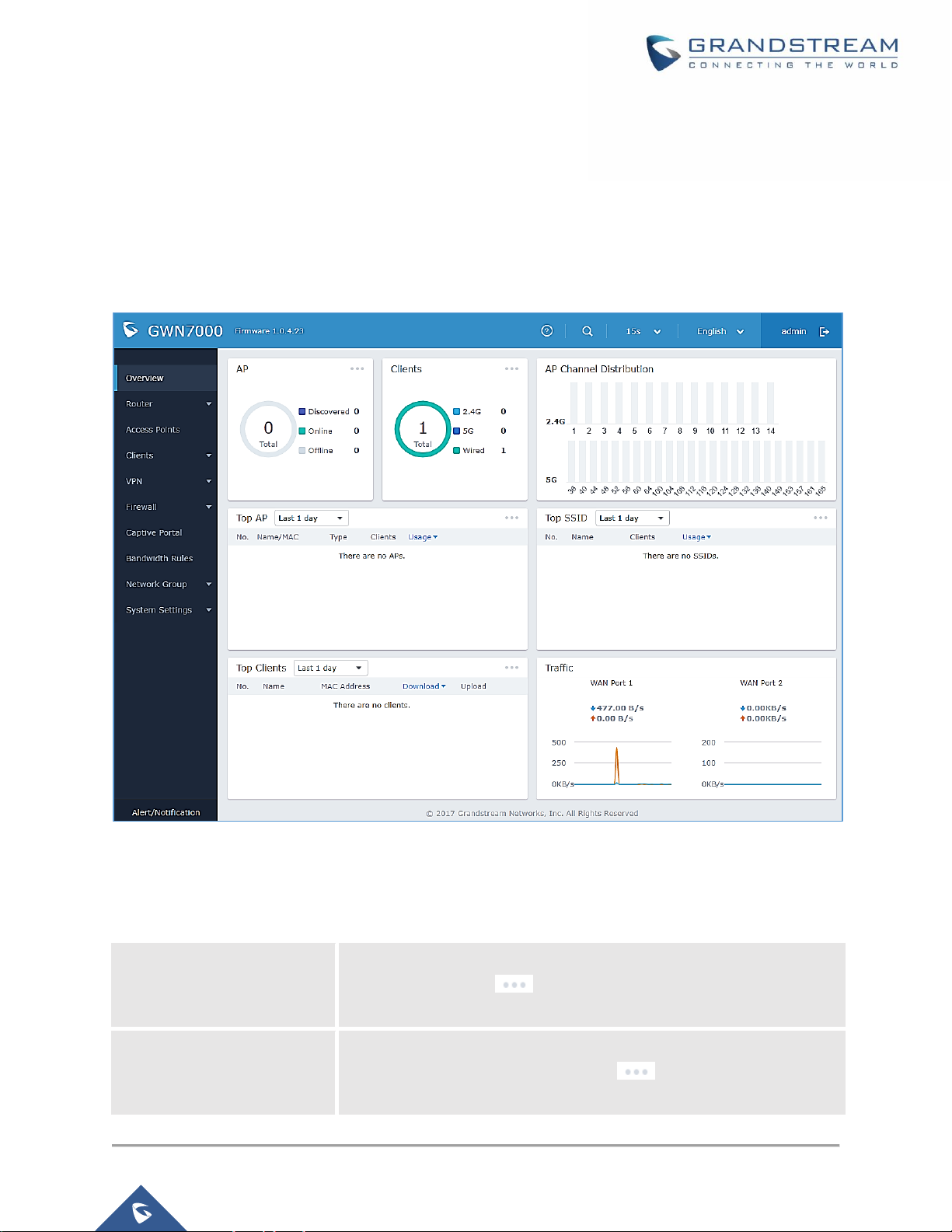
Overview is the first page shown after successful login to the GWN7000’s Web Interface. It provides an
overall view of the GWN7000’s information presented in a Dashboard style for easy monitoring.
Figure 8: Overview Page
It is used to show the status of the GWN7000 for different items, please refer to the following table for each
item:
Table 4: Overview
AP
Shows the number of Access Points that are Discovered, Paired (Online)
and Offline. Click on to go to Access Points’ page for basic and
advanced configuration options for the APs
Clients
Shows the total number of connected clients, and a count for clients
connected to each Channel. Click on to go to Clients page for
more options.
Page 23

P a g e | 23
GWN7000 User Manual
Version 1.0.4.23
AP Channel Distribution
Shows the Channel used for all APs that are paired with this Access
Point.
Top AP
Shows the Top APs list, assort the list by number of clients connected to
each AP or data usage combining upload and download. Click on
to go to Access Points page for basic and advanced configuration options
for the APs.
Top SSID
Shows the Top SSIDs list, assort the list by number of clients connected
to each SSID or data usage combining upload and download. Click on
to go to Network Group page for more options.
Top Clients
Shows the Top Clients list, assort the list of clients by their upload or
download. Click on to go to Clients page for more options.
Traffic
Shows the sent/received traffic data speeds on both WAN ports.
Note that Overview page in addition to other tabs can be updated each 15s, 1min, 2min, 5min or Never by
clicking in the upper bar menu (Default is 15s).
Save and Apply Changes
When clicking on "Save" button after configuring or changing any option on the web GUI pages. A message
mentioning the number of changes will appear on the upper menu.
Figure 9: Apply Changes
Click on button to apply changes, or to undo the changes.
Page 24
P a g e | 24
GWN7000 User Manual
Version 1.0.4.23
ROUTER CONFIGURATION
This section includes configuration pages for network WAN ports, static routes, QoS and DDNS and shows
also the router status.
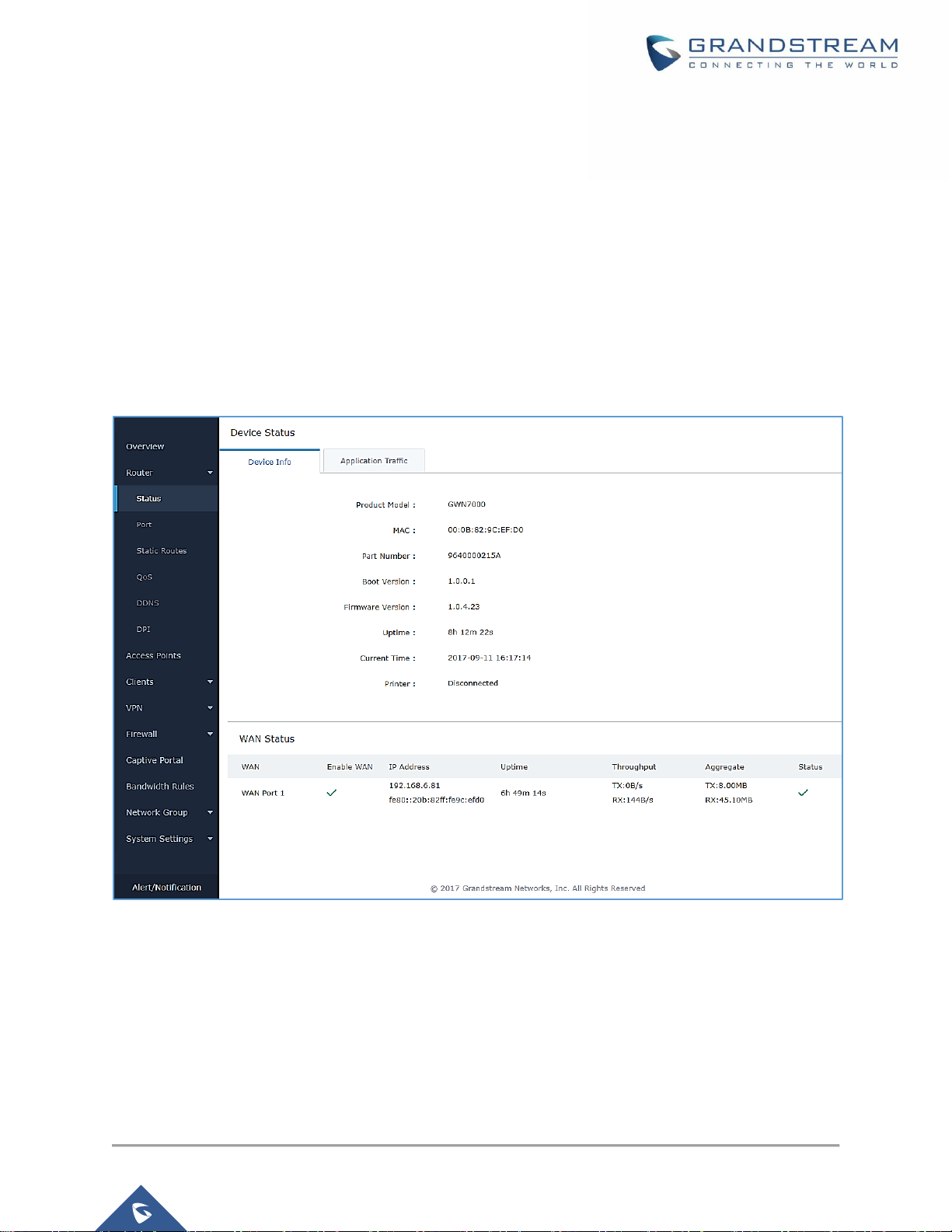
Status
Status page displays Device Status to check MAC address, Part Number, Firmware related information
and Uptime for the GWN7000; and WAN Status showing general information about WAN Ports such as
uptime, current throughput, aggregate usage, and IP address and also the application traffic.
Router’s Status page can be accessed from Web GUIRouterStatus.
Figure 10: Router's Status
Note: Once DPI is enabled under Router feature. Users will be able to see their application traffics under
Application Traffic section
Ports Configuration
Connect to GWN7000’s Web GUI from a computer connected to a LAN port and go to RouterPort page
for Port configuration.
Page 25

P a g e | 25
GWN7000 User Manual
Version 1.0.4.23
WAN Ports Settings
The GWN7000 has 2 WAN ports configured as DHCP clients by default. Each port can be connected with
DSL modem or routers. WAN ports support also setting static IPv4/IPv6 addresses, and configure PPPoE
for each WAN port. Please refer to the following table for basic network configuration parameters on WAN
ports for GWN7000.
Table 5: GWN7000 WEB GUIRouterPortWAN Port (1,2)
Enabled
Choose whether to enable or disable the WAN port.
Name
Specify the port name.
WAN Address Type
Select "DHCP", "Static" or "PPPoE" mode on the WAN interfaces of GWN7000.
The default setting is "DHCP".
• DHCP
When selected, it will act as a DHCP client and acquire an IPv4 address
automatically from the DHCP server.
• Static
When selected, the user should set a static IPv4 address, IPv4 Subnet Mask,
IPv4 Gateway and adding Additional IPv4 Addresses as well to
communicate with the web interface, SSH, or other services running on the
device.
• PPPoE
When selected, the user should set the PPPoE account and password, PPPoE
Keep alive interval and Inter-Key Timeout (in seconds).
Preferred IPv4 DNS
Enter the preferred DNS server address (IPv4 address). If Preferred DNS is set,
GWN7000 will use it in priority.
Alternate IPv4 DNS
Enter the Alternate DNS server address (IPv4 address). If Preferred DNS is set,
GWN7000 will use it in when the Preferred DNS fails.
Native IPv6
Used to enable assigning IPv6 address to GWN7000. Once checked users will be
able to configure following fields: “IPv6 Address Assignment”, “Preferred IPv6
DNS”, “Alternate IPv6 DNS” and “IPv6 Relay to LAN”.
IPv6 Address
Assignment
This option is appearing when enabling “Native IPv6” option.
Select "Auto" to get an IPv6 address from DHCP server or "Static" to configure
manually an IPv6 address. If set to Static, the following fields should be configured:
• IPv6 Address/Prefix Length
Used to set an IPv6 address/Prefix length when using Static IPv6 option
Example: fec0:470:28:5b2::1/64
• IPv6 Gateway
Used to define the Gateway’s IPv6 address.
• IPv6 Prefix/IPv6 Prefix Length
Enter the IPv6 prefix and IPv6 prefix length.
Example: ::1/64
Page 26

P a g e | 26
GWN7000 User Manual
Version 1.0.4.23
Preferred IPv6 DNS
This option appears only when “Native IPv6” option is enabled.
It is used to set a preferred DNS server address (IPv6 address). If Preferred DNS
is set, GWN7000 will use it in priority.
Alternate IPv6 DNS
This option appears only when “Native IPv6” option is enabled.
It is used to set an Alternate DNS server address (IPv6 address). If Preferred DNS
is set, GWN7000 will use it in when the Preferred DNS fails.
IPv6 Relay to LAN
This option appears only when “Native IPv6” option is enabled.
When enabled the GWN7000 will relay IPv6 address to LAN clients
Multi-WAN
These options are used when both WAN ports are enabled and using Failover
feature:
• Tracking IP
Configures the tracking IP(s). ICMP packets are being used to track the IP(s)
address(es). When the tracking fails, the GWN7000 will use the secondary
WAN port as failover. Default IP used is 8.8.8.8.
• Tracking Timeout (sec)
Configures tracking timeout in seconds. Default value is 2.
• Tracking Interval (sec)
Configures the track interval in seconds. Default value is 5.
• Bandwidth
Specifies the bandwidth for the port, e.g: “100k”, “1M” or “100M”.
VLAN Tagging
Used to enable VLAN tagging. If set to “0” the VLAN tagging will be disabled,
otherwise set a VLAN value between 5 and 4093. Default is 0.
Tunnel
Tunnel page is used to set IPv6 tunnels on WAN ports via IPv6 tunnel brokers service providers, this serves
the purpose of transferring IPv6 packets over IPv4 Network. It supports creating 6in4, 6rd and AICCU
tunnels. Please refer to below tables for each tunnel type.
Table 6: 6In4 Tunnels
WAN Interface
Choose the WAN port on which to setup the 6in4 tunnel.
MTU
Set the Maximum Transmission Unit value.
The valid range is 64-9000. Default value is 1500.
6in4 IPv4 Peer
Address
Enter the IPv4 tunnel endpoint at the tunnel’s provider.
6in4 Tunnel Endpoint
IPv6 Address
Enter the local IPv6 address delegated to the tunnel endpoint.
Example: 2001:db8:2222::2/64
6in4 Routed Prefix
Set the routable prefix given by the tunnel provider to allow LAN clients to get
addresses from that prefix.
Tunnel ID
Specifies the tunnel’s ID.
Username
Set the username used to login into the tunnel broker.
Page 27

P a g e | 27
GWN7000 User Manual
Version 1.0.4.23
Password
Set the password (used for endpoint update).
Update Key
Set the update key, it overrides the password used for endpoint update.
Table 7: 6rd Tunnels
WAN Interface
Choose the WAN port on which to setup the 6rd tunnel.
MTU
Set the Maximum Transmission Unit value.
The valid range is 64-9000 and default value is 1500.
6rd IPv4 Peer
Address
Enter the IPv4 Peer address.
6rd IPv6 Address
Prefix
Specifies the IPv6 prefix given by the provider.
Example: 2001:B000::/32
IPv6 Prefix Length
Specifies the IPv6 prefix length (Value between 1 and 128).
Example: 32
IPv4 Prefix Length
Specifies the prefix length of the IPv4 transport address.
(Value between 1 and 32).
Table 8: AICCU Tunnels
WAN Interface
Choose the WAN port on which to setup the aiccu tunnel.
Username
Enter the Username (Provided by signing up with SixXS Tunnel Broker)
Password
Enter the Username’s password
Global Settings
This section specifies operating mode for multi-WAN that will be used for enabling/disabling Failover and
Load Balancing on WAN ports, and banning MAC addresses.
The following table shows the configuration parameters for Multi-WAN settings
Table 9: GWN7000 WEB GUIRouterPortGlobal Settings
Multi-WAN
Specifies the operating mode for multi -WAN. Three options are available:
• Disabled
• Failover: Automatically switch to the connected WAN after failure.
• Load Balance + Failover: Operating the load balance mode, at the same
time automatically switch to the connected WAN after failure.
Disabled
This will disable Multi-WAN feature
Failover
If chosen failover will be enabled on WAN ports, admins need to choose the
Primary WAN port to be used.
When selected, user can set Multi-WAN parameters on WAN ports.
Page 28

P a g e | 28
GWN7000 User Manual
Version 1.0.4.23
Load Balance +
Failover
In addition to failover, load balance will be used on both ports to optimize the
resource utilization. Please note that for this feature to work, WAN ports should be
connected to different networks.
When selected, user can set Multi-WAN parameters on WAN ports.
Banned Client MAC
Shows the list of banned clients MAC addresses, other MAC addresses could be
also added by clicking on or removed by clicking on .
Port Mirroring
With port mirroring enabled, the GWN7000 will send a copy of all network packets seen on one LAN port
to another port, where the packet can be analyzed. Refer to the below table for the available fields to
configure.
Table 10: Port Mirroring
Enable Outgoing
Mirroring
Check to enable outgoing mirroring for a LAN port. Default is “Disabled”
Enable Incoming
Mirroring
Check to enable incoming mirroring for a LAN port. Default is “Disabled”
Mirroring Port
Select which LAN port that will be mirroring traffic. Default is “Disabled”
Mirrored Port
Select which LAN port that will act as mirrored port. Default is “Disabled”
Static Routes
GWN7000 supports setting manually static IPv4 and IPv6 routes as well as displaying routing table entries.
Static routes configuration page can be accessed from GWN7000 WebGUIRouterStatic Routes:
Three tabs are available:
- Routes to view routing table entries.
- IPv4 to create, edit or delete static IPv4 static routes.
- IPv6 to create, edit or delete static IPv6 static routes.
Following actions are available in both IPv4 and IPv6 tabs:
• To add a new static route, click on
• To edit a static route, click on
• To delete a static route, click on
Refer to the following tables when editing or creating IPv4/IPv6 static routes:
Page 29
P a g e | 29
GWN7000 User Manual
Version 1.0.4.23
Table 11: IPv4 Static Routes
Name
Enter the Name of the static route to be configured.
Enabled
Select whether to enable or disable this static route.
Group
Choose the LAN’s Network Group, which will be using this static route.
Target Network/Host
Enter the Network/Host IP address on which to route the traffic to.
Example: 192.168.5.0
Netmask
Enter the Network/Host Netmask.
Example: 255.255.255.0
NextHop
Enter the NextHop IP address.
Example: 192.168.5.1.
Metric
Set the metric value. The valid range is 0-255. Default value is 1.
Table 12: IPv6 Static Routes
Name
Enter the Name of the static route to be configured.
Enable
Select whether to enable or disable this static route.
Group
Choose the LAN’s Network Group
Target Network/Host
Enter the Network/Host IP address on which to route the traffic to.
2001:db8:3c4d:4::/64
NextHop
Enter the Gateway’s IP address.
fec0:470:28:5b2::1/64
Metric
Set the metric value. The valid range is 0-255. Default value is 1.
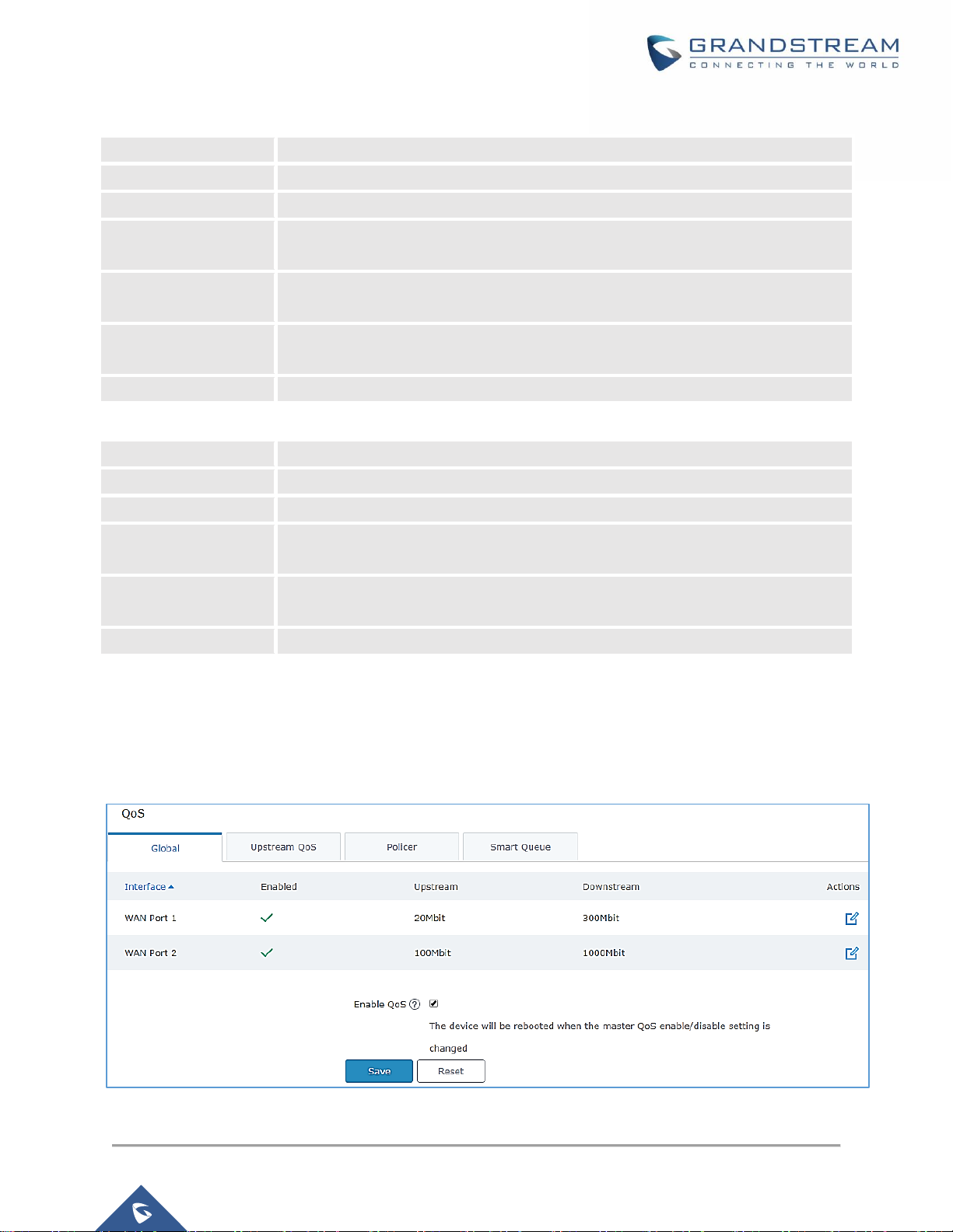
QoS
The GWN7000 offers the possibility to enable and configure QoS on both WAN and LAN interfaces, this
will help to manage in more depth the network traffic to define priority and classify different services and
protocols in a scheduled manner.
Figure 11: QoS
Page 30

P a g e | 30
GWN7000 User Manual
Version 1.0.4.23
To activate QoS, check “Enable QoS”. Three tabs are available for configuration:
• Basic: Download and upload bandwidth speeds settings on each WAN interface.
• Upstream QoS: Upstream QoS allows creating Traffic Classes to prioritize traffic for specific resources
on the network by controlling transmission/upload rate. Note that different classes can be created and
assigned as Traffic filters by respecting following conditions:
✓ The total of Upstream bandwidth values of each created class should not exceed the upstream
bandwidth value configured in Basic.
✓ The remaining bandwidth will be lent to the next priority level of class.
✓ All filter options are summed together.
• Policer: While Upstream QoS is dealing with traffic transmission, Policer is controlling the incoming
traffic. Thus, allowing to create rules to specific targets to set priority and received traffic rate, giving the
GWN7000 the ability to drop the exceeding traffic when reaching the configured maximum rate.
• Smart Queue: The smart queue is an integrated network system that performs better per-packet/per
flow network scheduling, reduces the buffer bloat and keeps latency at acceptable levels.
Refer to the following tables for each tab option:
Table 13: QoS Basic
Enabled
Check to enable upstream and downstream bandwidth speeds for the selected
WAN interface.
Upstream
Set the Upstream value to specify the upload bandwidth for selected interface, the
value should end with Mbit, Kbit or with no unit if the set value is referring to “bit”
unit. Note that the set value will affect and limit the bandwidth values on created
classes on QoS Upstream.
Examples: 500Mbit
100Kbit
500
Downstream
Set the Downstream value to specify the download bandwidth speed for selected
interface, the value should end with “Mbit”, “Kbit” or with no unit if the set value is
referring to “bit” unit.
Examples: 1000Mbit
100Kbit
500
Table 14: Upstream QoS
Traffic Class
Name
Define a name for the traffic class.
Priority
Set the priority of the traffic class, the lower the value, the highest the priority. Valid
range is between 1 and 64.
Page 31

P a g e | 31
GWN7000 User Manual
Version 1.0.4.23
Interface
Select the WAN interface from which the traffic will be classified, make sure to
enable the desired interface it from QoS Basic in order to appear.
Upstream
Set Upstream bandwidth value. The value should end with “Mbit”, “Kbit” or with no
unit if the set value is referring to “bit” unit.
Note that the sum of created classes should have upstream bandwidth speeds
lower than the Upstream bandwidth value configured on QoS Basic.
Examples: 100Mbit
100Kbit
500
Traffic Filter
Class
Select a class from created traffic classes using drop-down menu.
Name
Define a Name for the traffic filter rule.
DSCP
Choose the Differentiated Services Code Point (DSCP) value from drop-down list.
Default is 0.
IP Source Address
Specify the Source IP address from which the traffic filter rule will be applied.
IP Destination
Address
Specify the Destination IP address to which the traffic filter rule will be applied.
TCP Source Port
Specify the TCP Source port from which the traffic filter rule will be applied.
TCP Destination Port
Specify the TCP Source port to which the traffic filter rule will be applied.
UDP Source Port
Specify the UDP Source port from which the traffic filter rule will be applied.
UDP Destination Port
Specify the UDP Source port to which the traffic filter rule will be applied.
Group Source
Choose the LAN group of the specified Source IP address. If no Source IP address
has been defined, the rule will be applied to all members of that LAN group.
Table 15: QoS Policer
Name
Define a Name for the Policer rule.
Interface
Select an interface from which the traffic will be policed, make sure to enable the
desired interface it from QoS Basic in order to appear.
Priority
Set the priority of the traffic class, the lower the value, the highest the priority. Valid
range is between 1 and 64.
Rate
Set a Rate value for download bandwidth when applying policer rule.
DSCP
Choose the Differentiated Services Code Point (DSCP) value from drop-down list.
Default is 0.
IP Source Address
Specify the Source IP address from which the policer rule will be applied.
IP Destination
Address
Specify the Destination IP address to which the policer rule will be applied.
TCP Source Port
Specify the TCP Source port from which the policer rule will be applied.
TCP Destination Port
Specify the TCP Source port to which the policer rule will be applied.
Page 32

P a g e | 32
GWN7000 User Manual
Version 1.0.4.23
UDP Source Port
Specify the UDP Source port from which the policer rule will be applied.
UDP Destination Port
Specify the UDP Source port to which the policer rule will be applied.
Group Source
Choose the LAN group of the specified Source IP address.
If no Source IP address has been defined, the rule will be applied to all members
of that LAN group.
Table 16: QoS Smart Queue
Enabled
Check this option in order to enable the feature on the WAN interface.
Qdisc
Select which Queuing discipline method to use for QoS:
• fq_codel (Fair Queue with Controlled Delay)
• Cake
Manager
Choose the type of the smart queue management:
If fq_codel queuing discipline method is selected.
• simple: Three-tier prioritization system.
• simplest: HTB (Hierarchical Token Bucket) shaper with a single fq_codel
queuing discipline.
• simplest_tbf: TBF (Token Bucket Filter) shaper with a single fq_codel
queuing discipline.
If cake queuing discipline method is selected.
• layer_cake: Three-tier prioritization system with cake as a replacement
for HTB rate limiting.
• piece_of_cake: Single queue with cake as a replacement for HTB rate
limiting.
Link -layer
Adaptation
Select the link-layer type for the WAN connection. This can be used to compensate
for the link-layer overhead of certain types of WAN connections.
• None (default).
• Ethernet (should be selected for VDSL connections).
• ATM (should be selected for ADSL connections).
Overhead
If the link-layer is set to something other than “none”, then the link-layer overhead
setting can be used to specify how many bytes of overhead there are.
Defaults are 8 for Ethernet, and 44 for ATM.
Advanced Qdisc
Options
Check this option in order to show advanced Qdisc options to be used.
Squash DSCP on
ingress
Select whether to squash or not the DSCP on ingress packets. By default, this
option is disabled.
Page 33

P a g e | 33
GWN7000 User Manual
Version 1.0.4.23
Ignore DSCP on
ingress
Select whether to ignore DSCP on ingress packets or not. By default, this option
is disabled.
ECN Status on
Inbound packets
Select whether to set or not ECN status on inbound packets.
DDNS
DDNS allows accessing GWN7000 via domain name instead of IP address, the GWN7000 supports
following DDNS providers:
• Dyndns.org
• Changeip.com
• Zoneedit.com
• Free.editdns.net
• Freedns.afraid.org
• He.Net
• Dnsomatic.Com
• No-ip.pl
• Myonlineportal.net
Before configuring DDNS settings on the GWN7000, make sure first to create and confirm the DDNS
account via supported providers.
Following steps illustrates how to configure the DDNS settings on your GWN7000:
1. Access to GWN7000 web GUI, and navigate to RouterDDNS, and enable DDNS service.
2. Fill in the domain name created with DDNS provider under Domain Name field.
3. Enter your account username and password under Username and Password fields.
4. Specify the WAN interface to which DDNS is applied under Network interface field.
5. (Optional) For advanced configuration, it is also possible log to Syslog and m odify the values of
refreshing fields so to check periodically the updated IP address.
DPI
DPI stands for Deep Packet Inspection which is an option that allows the GWN7000 to analyze the core of
the packet to collect and report information at the Application-layer, such as traffic volume of an application
used by the host.
Snort OpenApp ID allows the System Administrator to view the internet traffic of users. The GUI displays
traffic data in a human-readable format, such as 'Streaming MP4 & Netflix - 31% of total traffic usage.' The
data is accompanied by a graph.
Page 34

P a g e | 34
GWN7000 User Manual
Version 1.0.4.23
GWN7000 is using Snort for packet inspection and displays traffic status under StatusApplication
Traffic as shown on the figure below.
Figure 12: DPI Status
The following table contains the description of the DPI configuration settings.
Table 17: DPI Settings
Enable Application
Tracking
Enables the application tracking. By default, it’s disabled.
Interface
Select the interface on which the application tracking will be performed. By default,
it’s WAN Port 1.
Note: A reboot is required after enabling Depp packet inspection in order for the feature to take effect.
Page 35

P a g e | 35
GWN7000 User Manual
Version 1.0.4.23
SETTING UP A WIRELESS NETWORK
The GWN7000 Enterprise Router provides the user with the capability to create a wireless network by
adding multiple GWN76xx series access points, with connectivity over the most common wireless standards
(802.11b/g/n) operating in both 2.4GHz and 5GHz range.
The GWN7000 integrates multiple layers of security including the IEEE 802.1x port-based authentication
protocol, Wired Equivalent Privacy (WEP), Wi-Fi Protected Access (WPA and WPA2) and firewall and VPN
tunnels.
This chapter will introduce how to discover, add the GWN76xx access points, create and manage Wi-Fi
Networks.
For more details about Grandstream GWN76xx Access points, refer to
http://www.grandstream.com/products/networking-solutions/wifi-access-points
Discover and Pair GWN76xx Access Points
The GWN76xx are powerful access points, which are fully compatible with the GWN7000 and can be added
with one click, provisioned and managed in an easy and intuitive way. Once a GWN76xx is successfully
connected and has an IP from the GWN7000 router, user can then pair it to the GWN7000 and associate it
with a Network Group.
To Pair a GWN76xx access point connected as LAN client to the GWN7000, follow the below steps:
1. Connect to the GWN7000 Web GUI and go to Access Points.
Figure 13: Discover AP
2. Click on to discover access points within GWN7000’s LAN Network, the following
page will appear.
Page 36

P a g e | 36
GWN7000 User Manual
Version 1.0.4.23
Figure 14: Discovered Devices
3. Click on Pair under Actions, to pair the discovered Access Point with the GWN7000.
4. The paired GWN76xx will appear Online, Click on to unpair it.
Figure 15: GWN7610 online
5. Click on next to paired access point to check device configuration for its status, users
connected to it and configuration, or select multiple GWN76xx APs from the same model, and
click on to apply same configuration on selected units.
6. Click on to configure client bridge on the selected access point. For more details about the
client bridge feature, please refer to Client Bridge.
Refer to below table for Device Configuration tabs.
Table 18: Device Configuration
Status
Shows the device’s status information such as Firmware version, IP
Address, Link Speed, Uptime, and Users count via different Radio
channels.
Clients
Shows the Clients connected to the GWN76xx access point.
Configuration
• Device Name: Set GWN76xx’s name to identify it along with its
MAC address.
Page 37

P a g e | 37
GWN7000 User Manual
Version 1.0.4.23
• Fixed IP: Used to set a static IP for the GWN76xx, if checked, the
following needs to be configured:
-IPv4 Address: Enter the IPv4 address to be set as static for the
device
-IPv4 Subnet Mask: Enter the Subnet Mask.
-IPv4 Gateway: Enter the Network Gateway’s IPv4 Address.
-Preferred IPv4 DNS: Enter the Primary IPv4 DNS.
-Alternate IPv4 DNS: Enter the Alternate IPv4 DNS.
• Frequency: Set the GWN76xx’s frequency, it can be either
2.4GHz, 5GHz or Dual-band.
• Enable Band Steering: When Frequency is set to Dual-Band,
check this option to enable Band Steering on the Access Point,
this will help redirecting clients to a radio band accordingly for
efficient use and to benefit from the maximum throughput
supported by the client.
• Mode: Choose the mode for the frequency band, 802.11n/g/b for
2.4Ghz and 802.11ac for 5Ghz.
• Channel Width: Choose the Channel Width, note that wide
channel will give better speed/throughput, and narrow channel
will have less interference. 20Mhz is suggested in very high-
density environment.
• 40MHz Channel Location: Configure the 40MHz channel
location when using 20MHz/40MHz in Channel Width, it can be
set it to be “Secondary Below Primary”, “Primary Below
Secondary” or “Auto”.
• Channel: Select “Auto” or a specific channel. Default is “Auto”.
Note that the proposed channels depend on Country Settings
under System Settings–>Maintenance.
• Enable Short Guard Interval: Check to activate this option to half
the guard interval (from 800ns to 400ns) ensuring that distinct
transmissions do not interfere with one another, this will help
increasing throughput.
• Active Spatial Streams: Choose active spatial stream. Available
options: “Auto”, “1 stream”, “2 streams” and “3 streams” (For
GWN7610).
Page 38

P a g e | 38
GWN7000 User Manual
Version 1.0.4.23
• Radio Power: Set the Radio Power depending on desired cell
size to be broadcasted, three options are available: “Low”,
“Medium” or “High”. Default is “High”.
• Allow Legacy Device(802.11b): This feature appears when
“Mode” option is set to “802.11g” or “802.11n”, it allows legacy
devices not supporting “802.11g/n” mode to connect using the
“802.11b” mode.
• Custom Wireless Power(dBm): allows users to set a custom
wireless power for both 5GHz/2.4GHz band, the value of this field
must be between 1 and 31.
Access Point location
GWN7000 router has an interesting feature to help users to locate different access points using blinking
LED, to do so go under the access points page then click on button as shown on the below figure and the
corresponding LED will start blinking its LEDs. This can help ease locating the Access points on a multi-
deployment site.
Figure 16: locating Access Points
Note: If a GWN76xx is not being paired, or the pair icon is grey color, make sure that it is not being paired
with another GWN7000 Router or GWN76xx Access Point acting as Master Controller, if yes, it needs to
be unpaired first, or reset to factory default settings to make it available for pairing.
Network Groups
GWN7000 supports creating up to 16 different Network groups separated by VLANs and adding paired
GWN76xx Access Points.
To access Network Groups configuration page, log in to the GWN7000 WebGUI and go to Network
GroupNetwork Group.
Page 39

P a g e | 39
GWN7000 User Manual
Version 1.0.4.23
Figure 17: Network Group
The GWN7000 will have a default network group named group0, click on to edit it, or click on
“Add” to add a new network group.
Figure 18: Add a New Network Group
When editing or adding a new network group, following tabs will appear to configure a network group:
Page 40

P a g e | 40
GWN7000 User Manual
Version 1.0.4.23
• Basic: Used to name the network group, and set a VLAN ID if adding a new network group, and
addressing plans, refer to below table for each field.
Table 19: Basic
Network Group Name
Specifies the name for the network group.
Enabled
Check to activate the newly created network group.
WAN Membership
Select the WAN port membership. Or use Multi-WAN option if enabled
under RouterPortGlobal Settings
LAN Membership
Select the LAN port membership.
VLAN
Check to enable VLAN. This field is appearing only when having more than
a network group.
VLAN ID
Set a VLAN ID. Valid range is between 2 and 4093.
Enable IPv4
Check to enable IPv4 addressing for this network group
IPv4 Static Address
Set a static IPv4 address for the network group when enabling IPv4.
Additional IPv4 Static
Address
Set an additional static IPv4 address for the network group when enabling
IPv4.
IPv4 Subnet Mask
Set the Subnet Mask.
DHCP Enabled for IPv4
Check to enable DHCP using IPv4. This will allow clients connected to this
network group to get IPv4 addresses automatically from GWN7000 acting
as DHCP server.
DHCP Start Address
Set the starting IPv4 address for this network group’s clients.
DHCP End Address
Set the ending IPv4 address for this network group’s clients
DHCP Lease Time
Set the lease time for DHCP clients, the value can be defined in hours,
minutes, or as “infinite”. Default lease time is “12h”.
DHCP Options
Set the DHCP options. Click on to add another option, and to
delete an option.
Example: 44,192.168.2.50 for DHCP option 44 and 192.168.2.50 is the
WINS server’s address. Please refer to the following link for DHCP options
syntax: https://wiki.openwrt.org/doc/howto/dhcp.dnsmasq
DHCP Gateway
Defines the IP address of the DHCP gateway.
DHCP Preferred DNS
Set the preferred DNS Servers via DHCP.
DHCP Alternate DNS
Set the alternate DNS Servers via DHCP.
DHCPv4 Relay Enabled
Enable this option, if you want the GWN7000 relays the DHCP requests
from clients to another DHCP server(s). Once checked Click on to
add another DHCPv4 Relay Target, and to delete a DHCPv4 Relay
Target.
Page 41

P a g e | 41
GWN7000 User Manual
Version 1.0.4.23
Enable IPv6
Check to enable IPv6 addressing for this network group.
IPv6 Relay from WAN
Check to allow GWN7000 to relay IPv6 DHCP request from network
group’s clients to WAN port.
DHCP Enabled for IPv6
Check weather to enable IPv6 DHCP server for this network group.
IPv6 Prefix for Assignment
Set the prefix value to be assigned to the network group. Valid range is
between 1 to 64. Example: 64 will assign /64 prefixes.
IPv6 Subnet Hint
Set the subnet mask value.
IPv6 Uplink
Select the WAN port.
Enable Landing Page
Check to enable landing page when connecting to this network group’s
Wi-Fi. This will allow setting a landing page URL where wireless users will
be redirected automatically to the configured URL.
Landing Page URL
Set the landing page URL to which clients will be redirected once
connected to the network group’s Wi-Fi.
• Wi-Fi: Please refer to the below table for Wi-Fi tab options
Table 20: Wi-Fi
Enable Wi-Fi
Check to enable Wi-Fi for the network group.
SSID
Set or modify the SSID name.
SSID Band
Select the Wi-Fi band the GWN will use, three options are available:
• Dual-Band
• 2.4GHz
• 5Ghz
SSID Hidden
Select to hide SSID. SSID will not be visible when scanning for Wi-Fi, to
connect a device to hidden SSID, potential wireless clients will need to
specify SSID name and authentication password manually.
Wireless Client Limit
Configure the limit for wireless client. If there’s an SSID per-radio on a
network group, each SSID will have the same limit. Setting a limit of 50 will
limit each SSID to 50 users independently. If set to 0 the limit is disabled.
Enable Captive Portal
Click on the checkbox to enable the captive portal feature.
Captive Portal Policy
Select the captive portal policy already created on the “Captive portal” web
page to be used in the created SSID.
Security Mode
Set the security mode for encryption. 5 options are available:
• WEP 64-bit: Using a static WEP key. The characters can only be
0-9 or A-F with a length of 10, or printable ASCII characters with a
length of 5.
Page 42

P a g e | 42
GWN7000 User Manual
Version 1.0.4.23
• WEP 128-bit: Using a static WEP key. The characters can only be
0-9 or A-F with a length of 26, or printable ASCII characters with a
length of 13.
• WPA/WPA2: Using “PSK” or “802.1x” as WPA Key Mode, with
“AES” or “AES/TKIP” Encryption Type.
• WPA2: Using “PSK” or “802.1x” as WPA Key Mode, with “AES” or
“AES/TKIP” Encryption Type. Recommended configuration for
authentication.
• Open: No password is required. Users will be connected without
authentication. Not recommended for security reasons.
Client Bridge Support
Configures the client bridge support to allows the access point to be
configured as a client for bridging wired only clients wirelessly to the
network. When an access point is configured in this way, it will share the
WiFi connection to the LAN ports transparently. Once a Network Group
has an Client Bridge Support enabled, the AP adopted in this Network
Group can be turned in to Bridge Client mode by click the Bridge button.
Client Time Policy
Configures the client time policy. Default is None.
Use MAC Filtering
Choose Blacklist/Whitelist to specify MAC addresses to be
excluded/included from connecting to the zone’s Wi-Fi. Default is
Disabled.
Client Isolation
Client isolation feature blocks any connection between Wireless clients
connected to GWN76xx’s Wi-Fi access point. Client isolation can be helpful
to increase security for Guest networks/Public WiFi. Available modes are:
• Internet Mode: Wireless clients will be allowed to access only the
internet services and they cannot access any of the management
services, either on the router nor the GWN76xx access points.
• Gateway MAC Mode: Wireless clients can only communicate with
the gateway, the communication between Wireless clients is
blocked and they cannot access any of the management services
on the GWN76xx access points.
• Radio Mode: Wireless clients can access to the internet services,
GWN7000 router and the access points GWN76xx but they cannot
communicate with other Wireless clients.
Page 43

P a g e | 43
GWN7000 User Manual
Version 1.0.4.23
Gateway MAC Address
This field is required when using Client Isolation, so users will not lose
access to the Network (usually Internet).
Type in the default LAN Gateway’s MAC address (router’s MAC address
for instance) in hexadecimal separated by “:”.
Example: 00:0B:82:8B:4D:D8
RSSI Enabled
Check to enable RSSI function, this will lead the AP to disconnect users
below the configured threshold in Minimum RSSI (dBm).
Minimum RSSI (dBm)
Enter the minimum RSSI value in dBm. If the signal value is lower than the
configured minimum value, the client will be disconnected. The input range
is from “-94” or “-1”.
Enable Voice Enterprise
Enable this feature to help clients of APs connected to the GWN7000 to
perform better roaming decision.
• The 802.11k standard helps clients to speed up the search for
nearby APs that are available as roaming targets by creating an
optimized list of channels. When the signal strength of the current
AP weakens, your device will scan for target APs from this list.
• When your client device roams from one AP to another on the
same network, 802.11r uses a feature called Fast Basic Service
Set Transition (FT) to authenticate more quickly. FT works with
both pre-shared key (PSK) and 802.1X authentication methods.
Enable 11R
Enable 11K
Enable 11V
11R, 11V, 11K respectively represents the feature sets the three protocols
802.11r, 802.11v, 802.11k specifies, enterprise audio is a function based
on these feature sets, and 11R is required, without this function, the
enterprise audio will be unavailable.
Upstream Rate
Set a limitation of upload speed on the SSID.
Downstream Rate
Set a limitation of download speed on the SSID.
• Device Membership: Used to add or remove paired access points to the network group.
Page 44

P a g e | 44
GWN7000 User Manual
Version 1.0.4.23
Figure 19: Device Membership
Click on to add the GWN76xx to the network group, or click on to remove it.
• Wi-Fi Schedule: Used to schedule the times when the Wi-Fi is ON or OFF.
In the below example, the Wi-Fi is scheduled to be active Monday starting from 8:00 AM until 5:00 PM.
Note: The hour field is in 24 format (from 0 to 23). Valid range for minutes is 0-59.
Page 45

P a g e | 45
GWN7000 User Manual
Version 1.0.4.23
Figure 20: Wi-Fi Schedule
Note:
The schedule feature is based on SSID and not network group, meaning that you can schedule the
broadcasting of different SSID on different periods of the day.
Users can Also add a device to a Network Group from Access Points Page:
- Select the desired AP to add to a Network Group and click on .
Page 46

P a g e | 46
GWN7000 User Manual
Version 1.0.4.23
Figure 21: Add AP to Network Group from Access Points Page
- Check to select the desired Network, on which the selected APs will be added, as shown in the
above figure.
Create an SSID under a Network Group
Under Network Group Page, click to edit a network group or create a new network group and go to Wi-Fi
tab.
Page 47

P a g e | 47
GWN7000 User Manual
Version 1.0.4.23
Figure 22: Create an SSID
Refer to [Table 20: Wi-Fi] for Wi-Fi options.
Additional SSID under Same Network Group
GWN7000 provides the ability to create an additional SSID under the same group.
To create an additional SSID go to Network GroupAdditional SSID.
Page 48

P a g e | 48
GWN7000 User Manual
Version 1.0.4.23
Figure 23: Additional SSID
Select one of the available network groups from Network Group Membership dropdown menu; this will
create an additional SSID with the same Device Membership configured when creating the main network
group.
Figure 24: Additional SSID Created
Click on to delete the additional SSID, or to edit it.
Page 49

P a g e | 49
GWN7000 User Manual
Version 1.0.4.23
Client Bridge
The Client Bridge feature allows an access point to be configured as a client for bridging wired only clients
wirelessly to the network. When an access point is configured in this way, it will share the WiFi connection
to the LAN ports transparently. This is not to be confused with a mesh setup. The client will not accept
wireless clients in this mode.
Once a Network Group has an Client Bridge Support enabled, the AP adopted in this Network Group can
be turned in to Bridge Client mode by click the Bridge button .
Please be noted that once an AP it turned into Client Bridge mode, it cannot be controlled by a Master
anymore, and a factory reset is required to turn it back into normal AP mode.
Figure 25: Client Bridge
Important Notes:
• The access point that will be operating on bridge mode, must be set with a fixed IP address before
activating the bridge mode on the access point.
• Users must enable client bridge support option under network group or SSID WiFi settings in order
to have it fully functional. See [Client Bridge Support]
Page 50

P a g e | 50
GWN7000 User Manual
Version 1.0.4.23
CLIENTS CONFIGURATION
Clients
Connected clients to different network groups can be shown and managed from a single interface.
Clients list can be accessed from GWN7000’s Web GUIClients to perform different actions to wired and
wireless clients.
GWN7000 Enterprise Router with its DHCP server enabled on LAN ports level, will assign automatically an
IP address to the devices connected to its LAN ports like a computer or GWN76xx access points and to
wireless clients connected to paired GWN76xx access points.
Figure 26: Clients
Click on under Actions to check a client’s status and modify its configuration.
Status
Used to check user’s basic information such as MAC address, IP address, which Network group does it
belong to, and to which access point if it is a wireless client, as well as Throughput and Aggregate usage.
Page 51

P a g e | 51
GWN7000 User Manual
Version 1.0.4.23
Figure 27: Client's Status
Edit IP and Name
Configuration tab allowing to set a name for a client and set a static IP.
Figure 28: Client's Configuration
Bandwidth Rules
As mentioned on the BANDWIDTH RULES section, users can set bandwidth rules for upstream and
downstream links per SSID, or per Client. For Clients users can set bandwidth rules by navigating to the
menu ClientEditBandwidth Rules then click add new item.
Page 52

P a g e | 52
GWN7000 User Manual
Version 1.0.4.23
The following figure shows the settings:
Figure 29: Client Bandwidth Rules
Block a client
To block a client, click on under actions, this will add automatically the blocked client to Banned Client
MAC list under RouterPortGlobal Settings.
Figure 30: Block a Client
To unban a client, go to RouterPortGlobal Settings. Click on to remove it from the banned list.
Figure 31: Unban Client
Clients Access
From this menu, users can manage in global and way the blacklist of clients that will be blocked from
accessing the W iFi network, click on to add or remove MAC addresses of client from
global blacklist.
Page 53

P a g e | 53
GWN7000 User Manual
Version 1.0.4.23
Figure 32: Global Blacklist
Figure 33: Managing the Global Blacklist
A second option, is to add custom access lists that will be used as matching mechanism for MAC address
filtering option under network groups and SSIDs to allow (whitelist) or disallow (blacklist) clients access to
the WiFi network. Click on in order to create new access list, then fill it with all MAC addresses
to be matched. Once this is done, this access list can be used under network group or SSID WiFi settings
to filter clients either using whitelist or blacklist mode.
Figure 34: Blacklist Access List
Time Policy
The timed client disconnect feature allows the system administrator to set a fixed time for which clients
should be allowed to connect to the access point, after which the client will no longer be allowed to connect
for a user configurable cool-down period. The configuration is based on a policy where the administrator
can set the amount of time for which clients are allowed to connect to the WiFi and reconnect type and
value after which they will be allowed to connect back after they have been disconnected.
Page 54

P a g e | 54
GWN7000 User Manual
Version 1.0.4.23
In order to create a new policy, go under ClientsTime Policy and add new one., then the following
parameters:
Table 21: Time Policy Parameters
Option
Description
Name
Enter the name of the policy
Enabled
Check the box to enable the policy
Limit Client Connection Time
Sets amount of time a client may be connected.
Client Reconnect Timeout Type
Select the method with which we will reset a client’s connection timer
so they may reconnect again. Options are:
• Reset Daily.
• Reset Weekly.
• Reset Hourly.
• Timed Reset.
Client Reconnect Timeout
If ‘Timed Reset’ is selected, this is the period for which the client will
have to wait before reconnecting.
Reset Day
If Reset Weekly is selected, this is the day the reset will be applied.
Reset Hour
If Reset Weekly or Reset Daily is select, this is the hour and day the
reset will be applied.
Note: Time tracking shall be accounted for on a per-policy basis, such that a client connected to any SSID
assigned the time tracking policy will accrue a common counter, regardless of which SSID they are
connected to (as long as those SSIDs all share the same time tracking policy).
Banned Clients
Click on to view the list of the clients that have been banned after time disconnect feature
has taken effect, these clients will not be allowed to connect back until timeout reset or you can unblock a
client by clicking on the icon .
Figure 35: Ban/Unban Client
Page 55

P a g e | 55
GWN7000 User Manual
Version 1.0.4.23
VPN (VIRTUAL PRIVATE NETWORK)
Overview
VPN allows the GWN7000 to be connected to a remote VPN server using PPTP, L2TP/IPSec and
OpenVPN® protocols, or configure an OpenVPN® server and generate certificates and keys for clients,
VPN page can be accessed from the GWN7000 Web GUIVPN.
OpenVPN® Server Configuration
To use the GWN7000 as an OpenVPN® server, you will need to start creating OpenVPN® certificates and
client certificates. Before generating server/client certificates, it is requested to generate first the Certificate
Authority (CA), which will help to issue server/clients certificates.
GWN7000 certificates can be managed from WebGUISystem SettingsCert. Manager.
Generate Self-Issued Certificate Authority (CA)
A certificate authority (CA) is a trusted entity that issues electronic documents that verify a digital entity's
identity on the Internet. The electronic documents (a.k.a. digital certificates) are an essential part of secure
communication and play an important part in the public key infrastructure (PKI).
To create a Certification Authority (CA), follow below steps:
1. Navigate to “System SettingsCert. ManagerCAs” on the GWN7000 web GUI.
2. Click on button. A popup window will appear.
3. Enter the CA values including CN, Key Length, and Digest algorithm… depending on your needs.
Refer to below figure showing an example of configuration and below table showing all available
options with their respective description.
Page 56

P a g e | 56
GWN7000 User Manual
Version 1.0.4.23
Figure 36: Create CA Certificate
Table 22: CA Certificate
Field
Description
Common Name
Enter the common name for the CA.
It could be any name to identify this certificate.
Example: “CATest”.
Key Length
Choose the key length for generating the CA certificate.
Following values are available:
• 1024: 1024-bit keys are no longer sufficient to protect
against attacks.
• 2048: 2048-bit keys are a good minimum.
(Recommended).
Page 57

P a g e | 57
GWN7000 User Manual
Version 1.0.4.23
• 4096: 4096-bit keys are accepted by nearly all RSA
systems. Using 4096-bit keys will dramatically increase
generation time, TLS handshake delays, and CPU usage
for TLS operations.
Digest Algorithm
Choose the digest algorithm:
• SHA1: This digest algorithm provides a 160-bit fingerprint
output based on arbitrary length input.
• SHA-256: This digest algorithm generates an almost-
unique, fixed size 256-bit (32-byte) hash. Hash is a one-way
function – it cannot be decrypted back.
Lifetime (days)
Enter the validity date for the CA certificate in days.
In our example, set to “120”.
Country Code
Select a country code from the dropdown list.
Example: “MA”.
State or Province
Enter a state name or province.
Example: “Casablanca”.
City
Enter a city name.
Example: “Casablanca”.
Organization
Enter the organization name.
Example: “GS”.
Organization Unit
Enter the organization unit name.
Example: “Gs”.
Email Address
Enter an email address.
Example: “grandstream@gmail.com”
4. Click on button after completing all the fields for the CA certificate.
5. Click on button to export the CA to local computer. The CA file has extension “.crt”.
Page 58

P a g e | 58
GWN7000 User Manual
Version 1.0.4.23
Figure 37: CA Certificate
Generate Server/Client Certificates
Create both server and client certificates for encrypted communication between clients and GWN7000
acting as an OpenVPN® server.
❖ Creating Server Certificate
To create server certificate, follow below steps:
1. Navigate to “System SettingsCert. ManagerCertificates”.
2. Click on button. A popup window will appear.
Refer to below figure showing an example of configuration and below table showing all available
options with their respective description.
Page 59

P a g e | 59
GWN7000 User Manual
Version 1.0.4.23
Figure 38: Generate Server Certificates
Table 23: Server Certificate
Field
Description
Common Name
Enter the common name for the server certificate.
It could be any name to identify this certificate.
Example: “ServerCertificate”.
CA Certificate
Select CA certificate previously generated from the drop-down list.
Example: “CATest”.
Page 60

P a g e | 60
GWN7000 User Manual
Version 1.0.4.23
Certificate Type
Choose the certificate type from the drop-down list. It can be either
a client or a server certificate.
Choose “Server” to generate server certificate.
Key Length
Choose the key length for generating the server certificate.
Following values are available:
• 1024: 1024-bit keys are no longer sufficient to protect
against attacks. Not recommended.
• 2048: 2048-bit keys are a good minimum. Recommended.
• 4096: 4096-bit keys are accepted by nearly all RSA
systems. Using 4096-bit keys will dramatically increase
generation time, TLS handshake delays, and CPU usage
for TLS operations.
Digest Algorithm
Choose the digest algorithm:
• SHA1: This digest algorithm provides a 160-bit fingerprint
output based on arbitrary length input.
• SHA-256: This digest algorithm generates an almost-
unique, fixed size 256-bit (32-byte) hash. Hash is a one-way
function – it cannot be decrypted back
Lifetime (days)
Enter the validity date for the server certificate in days.
In our example, set to “120”.
Country Code
Select a country code from the dropdown list.
Example: “MA”.
State or Province
Enter a state name or province.
Example: “Casablanca”.
City
Enter a city name.
Example: “Casablanca”.
Organization
Enter the organization name.
Example: “GS”.
Email Address
Enter an email address.
Example: “Cert@grandstream.com”.
3. Click on button after completing all the fields for the server certificate.
Page 61

P a g e | 61
GWN7000 User Manual
Version 1.0.4.23
Click on button to export the server certificate file in “.crt” format.
Click on button to export the server key file in “. key” format.
Click on button to revoke the server certificate if no longer needed.
Notes:
• The server certificates (.crt and .key) will be used by the GWN7000 when acting as a server.
• The server certificates (.crt and .key) can be exported and used on another OpenVPN® server.
❖ Creating Client Certificate
To create client certificate, follow below steps:
1- Create Users
a. Navigate to “System SettingsUser Manager”.
b. Click on button. The following window will pop up.
Figure 39: User Management
c. Enter User information based on below descriptions.
Page 62

P a g e | 62
GWN7000 User Manual
Version 1.0.4.23
Field
Description
Enabled
Check to enable the user.
Full Name
Choose full name to identify the users.
Username
Choose username to distinguish client’s certificate.
Password
Enter user password for each username.
IPSec Pre-Shared Key
Enter the pre-shared key to connect to VPN server.
This field is used when clients are using pre-shared key.
d. Repeat above steps for each user.
2- Create Client Certificate
a. Navigate under “System SettingsCert. ManagerCertificates”.
b. Click on button. The following window will pop up.
c. Enter client certificate information based on below descriptions.
Page 63

P a g e | 63
GWN7000 User Manual
Version 1.0.4.23
Figure 40: Client Certificate
Table 24: Client Certificate
Field
Description
Common Name
Enter the common name for the client certificate.
It could be any name to identify this certificate.
Example: “ClientCertificate”.
CA Certificate
Select the generated CA certificate from the drop-down list.
Certificate Type
Choose the certificate type from the drop-down list.
It can be either a client or server certificate.
Page 64

P a g e | 64
GWN7000 User Manual
Version 1.0.4.23
Username
Select created user to generate his certificate.
Key Length
Choose the key length for generating the client certificate.
Following values are available:
• 1024: 1024-bit keys are no longer sufficient to protect
against attacks. Not recommended.
• 2048: 2048-bit keys are a good minimum. Recommended.
• 4096: 4096-bit keys are accepted by nearly all RSA
systems. Using 4096-bit keys will dramatically increase
generation time, TLS handshake delays, and CPU usage
for TLS operations.
Digest Algorithm
Choose the digest algorithm:
• SHA1: This digest algorithm provides a 160-bit fingerprint
output based on arbitrary length input.
• SHA-256: This digest algorithm generates an almost-
unique, fixed size 256-bit (32-byte) hash. Hash is a one-way
function – it cannot be decrypted back
Lifetime (days)
Enter the validity date for the client certificate in days.
Example: “120”.
Country Code
Select a country code from the dropdown list.
Example: “MA”.
State or Province
Enter a state name or province.
Example: “Casablanca”.
City
Enter a city name.
Example: “Casablanca”.
Organization
Enter the organization name.
Example: “GS”.
Email Address
Enter an email address.
Example: “user@grandstream.com”.
d. Click on after completing all the fields for the client certificate.
e. Click on to export the client certificate file in “.crt” format.
f. Click on to export the client key file in “.key” format.
Page 65

P a g e | 65
GWN7000 User Manual
Version 1.0.4.23
Click on to revoke the client certificate if no longer needed.
The client certificates (“.crt” and “.key”) will be used by clients connected to the GWN7000 in order to
establish TLS handshake.
Notes:
• Client certificates generated from the GWN7000 need to be uploaded to the clients.
• For security improvement, each client needs to have his own username and certificate, this way
even if a user is compromised, other users will not be affected.
Create OpenVPN® Server
Once client and server certificates are successfully created, you can create a new server, so that clients
can be connected to it, by navigating under “VPNOpenVPN®Server”.
To create a new VPN server, follow below steps:
1. Click on and the following window will pop up.
Page 66

P a g e | 66
GWN7000 User Manual
Version 1.0.4.23
Figure 41: Create OpenVPN® Server
Table 25: OpenVPN® Server
Field
Description
Enable
Click on the checkbox in order to enable the OpenVPN® server
feature.
VPN Name
Enter a name for the OpenVPN® server.
Server Mode
Choose the server mode the OpenVPN® server will operate with.
4 modes are available:
Page 67

P a g e | 67
GWN7000 User Manual
Version 1.0.4.23
• PSK: used to establish a point-to-point OpenVPN®
configuration. A VPN tunnel will be created with a server
endpoint of a specified IP and a client endpoint of specified
IP. Encrypted communication between client and server will
occur over UDP port 1194, the default OpenVPN® port.
• SSL: Authentication is made using certificates only (no
user/pass authentication). Each user has a unique client
configuration that includes their personal certificate and key.
This is useful if clients should not be prompted to enter a
username and password, but it is less secure as it relies
only on something the user has (TLS key and certificate).
• User Auth: Authentication is made using only CA, user and
password, no certificates. Useful if the clients should not
have individual certificates.
Less secure as it relies on a shared TLS key plus only
something the user knows (Username/password).
• SSL + User Auth: Requires both certificate and username
/ password. Each user has a unique client configuration that
includes their personal certificate and key.
Most secure, as there are multiple factors of authentication
(TLS Key and Certificate that the user has, and the
username/password they know).
Protocol
Choose the Transport protocol from the dropdown list, either TCP or
UDP. The default protocol is UDP.
Interface
Select the interface used to connect the GWN7000 to the uplink,
either WAN1, WAN2 or All.
Local Port
Configure the listening port for OpenVPN® server.
The default value is 1194.
Encryption Algorithm
Choose the encryption algorithm from the drop-down list, in order to
encrypt data so that the receiver can decrypt it using same algorithm.
Digest Algorithm
Choose the digest algorithm from the drop-down list, which will
uniquely identify the data to provide data integrity and ensure that
the receiver has an unmodified data from the one sent by the original
host.
Page 68

P a g e | 68
GWN7000 User Manual
Version 1.0.4.23
TLS Authentication
This option uses a static Pre-Shared Key (PSK) that must be
generated in advance and shared among all peers. This feature
adds extra protection to the TLS channel by requiring that incoming
packets have a valid signature generated using the PSK key.
TLS Pre-Shared Key
Enter the generated TLS Pre-Shared Key when using TLS
Authentication.
Certificate Authority
Select a generated CA from the drop-down list.
Server Certificate
Select a generated Server Certificate from the drop-down list.
IPv4 Tunnel Network
Enter the network range that the GWN7000 will be serving from to
the OpenVPN® client.
Note: The network format should be the following 10.0.10.0/16.
The mask should be at least 16 bits.
Redirect Gateway
When redirect-gateway is used, OpenVPN® clients will route DNS
queries through the VPN, and the VPN server will need to handle
them.
Automatic Firewall Rule
Enable automatic firewall rule.
Auto Forward Group Traffic
If enabled, choose which groups you want to forward, if not, you can
manually configure the forward rules under firewall settings.
LZO Compression
Select whether to activate LZO compression or no, if set to
“Adaptive”, the server will make the decision whether this option will
be enabled or no.
Allow Peer to Change IP
Allow remote change the IP and/or Port, often applicable to the
situation when the remote IP address changes frequently.
2. Click after completing all the fields.
3. Click on top of the WebGUI in order to apply changes.
Figure 42: OpenVPN®
Page 69

P a g e | 69
GWN7000 User Manual
Version 1.0.4.23
OpenVPN® Client configuration
The GWN7000 act as both, an OpenVPN® client and server, once users and client certificate created,
navigate under “VPNOpenVPN®Client” and follow steps below:
1. Click on and the following window will pop up.
Figure 43: OpenVPN® Client
Page 70

P a g e | 70
GWN7000 User Manual
Version 1.0.4.23
Table 26: OpenVPN® Client
Field
Description
Enable
Click on the checkbox to enable the OpenVPN® client feature.
VPN Name
Enter a name for the OpenVPN® client.
Protocol
Choose the Transport protocol from the dropdown list, either TCP or
UDP. The default protocol is UDP.
Interface
Select the interface used to connect the GWN7000 to the uplink,
either WAN1, WAN2 or All.
Local Port
Configure the listening port for OpenVPN® server. Default is 1194.
Remote OpenVPN® Server
Configure the remote OpenVPN® server IP address.
Remote OpenVPN® Server
Port
Configure the remote OpenVPN® server port.
Auth Mode
Choose the server mode the OpenVPN® server will operate with, 4
modes are available:
• PSK: used to establish a point-to-point OpenVPN®
configuration. A VPN tunnel will be created with a server
endpoint of a specified IP and a client endpoint of specified
IP. Encrypted communication between client and server will
occur over UDP port 1194, the default OpenVPN® port.
• SSL: Authentication is made using certificates only (no
user/pass authentication). Each user has a unique client
configuration that includes their personal certificate and key.
This is useful if clients should not be prompted to enter a
username and password, but it is less secure as it relies
only on something the user has (TLS key and certificate).
• User Auth: Authentication is made using only CA, user and
password, no certificates. Useful if the clients should not
have individual certificates.
Less secure as it relies on a shared TLS key plus only
something the user knows (Username/password).
• SSL + User Auth: Requires both certificate and username
/ password. Each user has a unique client configuration
that includes their personal certificate and key.
Most secure, as there are multiple factors of authentication
(TLS Key and Certificate that the user has, and the
username/password they know).
Page 71

P a g e | 71
GWN7000 User Manual
Version 1.0.4.23
Encryption Algorithm
Choose the encryption algorithm from the drop-down list, in order to
encrypt data so that the receiver can decrypt it using the same
algorithm.
Digest Algorithm
Choose the digest algorithm from the drop-down list, which will
uniquely identify the data to provide data integrity and ensure that
the receiver has an unmodified data from the one sent by the original
host.
TLS Authentication
This option uses a static Pre-Shared Key (PSK) that must be
generated in advance and shared among all peers.
This feature adds extra protection to the TLS channel by requiring
that incoming packets have a valid signature generated using the
PSK key.
TLS Pre-Shared Key
Enter the generated TLS Pre-Shared Key when using TLS
Authentication.
Auto Forward Group Traffic
If enabled, choose which groups you want to forward, if not, you can
manually configure the forward rules under firewall settings.
Network Group
Select the Network group to which the client belongs, or select All
Network Groups.
Routes
This feature allows specifying and adding custom routes.
Don’t Pull Routes
If enabled, client will ignore routes pushed by the server.
Force Default Route through
Server
Force a default route to the server.
IP Masquerading
This feature is a form of network address translation (NAT) which
allows internal computers with no known address outside their
network, to communicate to the outside. It allows one machine to act
on behalf of other machines.
LZO Compression
LZO encoding provides a very high compression ratio with good
performance. LZO encoding works especially well for CHAR and
VARCHAR columns that store very long character strings.
Allow Peer to Change IP
Allow remote change the IP and/or Port, often applicable to the
situation when the remote IP address changes frequently.
CA Certificate
Click on “Upload” and select the “CA” certificate generated
previously on this guide.
Client Certificate
Click on “Upload” and select the “Client Certificate” generated
previously on this guide.
Page 72

P a g e | 72
GWN7000 User Manual
Version 1.0.4.23
Client Private Key
Click on “Upload” and select the “Client Private Key” generated
previously on this guide.
Client Private Key Password
Enter the client private key password
2. Click after completing all the fields.
3. Click on top of the webGUI in order to apply changes.
Figure 44: OpenVPN® Client
L2TP/IPSEC Configuration
Layer 2 Tunneling Protocol (L2TP) is a tunneling protocol used to support virtual private networks (VPNs)
or as part of the delivery of services by ISPs. It does not provide any encryption or confidentiality by itself.
Rather, it relies on an encryption protocol that it passes within the tunnel to provide privacy.
GWN7000 L2TP/IPSec Client Configuration
To configure L2TP client on the GWN7000, navigate under “VPNL2TP/IPSec” and set the following:
1- Click on and the following window will pop up.
Page 73

P a g e | 73
GWN7000 User Manual
Version 1.0.4.23
Figure 45: L2TP Client Configuration
Table 27: L2TP Configuration
Field
Description
Enable
Click on the checkbox in order to enable the L2TP client feature.
VPN Name
Enter a name for the L2TP client.
WAN Port
Select which WAN port is connected to the uplink, either WAN1 or
WAN2.
Remote L2TP Server
Enter the IP/Domain of the remote L2TP Server.
Username
Enter the Username for authentication against the VPN Server.
Password
Enter the Password for authentication against the VPN Server.
Page 74

P a g e | 74
GWN7000 User Manual
Version 1.0.4.23
Connection Type
Select either Transport mode or Tunnel mode:
• Transport mode is commonly used between end stations
or between an end station and a gateway, if the gateway is
being treated as a host.
• Tunnel mode is used between gateways, or at an end
station to a gateway, the gateway acting as a proxy for the
hosts behind it.
Pre-Shared Key
Enter the L2TP pre-shared key.
Auto Forward Group Traffic
If enabled, choose which groups you want to forward, if not, you can
manually configure the forward rules under firewall settings.
Remote Subnet
Configures the remote subnet for the VPN.
The format should be “IP/Mask” where IP could be either IPv4 or
IPv6 and mask is a number between 1 and 32.
For example: 192.168.5.0/24
Use Tunnel as Default Route
Enable this option so that L2TP/IPSec VPN Tunnel will be used by
default.
IP Masquerading
This feature is a form of network address translation (NAT) which
allows internal computers with no known address outside their
network, to communicate to the outside. It allows one machine to act
on behalf of other machines.
Use DNS from Server
Enable this option to retrieve DNS from the VPN server.
Number of Attempts to
Reconnect
Configures the number of attempts to reconnect the L2TP client, if
this number is exceeded, the client will be disconnected from the
L2TP/IP Server.
Use Built-in IPv6 management
Enable the IPv6 management for the VPN.
Port Forwarding Rules
Enter the port-forwarding rule to be used for the VPN.
Port Trigger Rules
Enter the port trigger rule to be used for the VPN.
2- Click after completing all the fields.
3- Click on top of the web GUI to apply changes.
Page 75

P a g e | 75
GWN7000 User Manual
Version 1.0.4.23
Figure 46: L2TP Client
PPTP CONFIGURATION
A data-link layer protocol for wide area networks (WANs) based on the Point-to-Point Protocol (PPP) and
developed by Microsoft that enables network traffic to be encapsulated and routed over an unsecured public
network such as the Internet. Point-to-Point Tunneling Protocol (PPTP) allows the creation of virtual private
networks (VPNs), which tunnel TCP/IP traffic through the Internet.
GWN7000 Client Configuration
To configure PPTP client on the GWN7000, navigate under “VPNPPTP” and set the following:
1- Click on and the following window will pop up.
Page 76

P a g e | 76
GWN7000 User Manual
Version 1.0.4.23
Figure 47: PPTP Client Configuration
Table 28: PPTP Configuration
Field
Description
Enable
Click on the checkbox to enable the PPTP VPN client feature.
VPN Name
Enter a name for the PPTP client.
Remote PPTP Server
Enter the IP/Domain of the remote PPTP Server.
Page 77

P a g e | 77
GWN7000 User Manual
Version 1.0.4.23
Username
Enter the Username for authentication against the VPN Server.
Password
Enter the Password for authentication against the VPN Server.
Auto Forward Group Traffic
If enabled, choose which groups you want to forward, if not, you can
manually configure the forward rules under firewall settings.
Subnet
Configures the remote subnet for the VPN.
The format should be “IP/Mask” where IP could be either IPv4 or
IPv6 and mask is a number between 1 and 32.
For example: 192.168.5.0/24
Use Tunnel as Default Route
Enable this option so that PPTP VPN Tunnel will be used by default.
IP Masquerading
This feature is a form of network address translation (NAT) which
allows internal computers with no known address outside their
network, to communicate to the outside. It allows one machine to act
on behalf of other machines.
Use DNS from Server
Enable this option to retrieve DNS from the VPN server.
Number of Attempts to
Reconnect
Configures the number of attempts to reconnect the PPTP client, if
this number is exceeded, the client will be disconnected from the
PPTP Server.
Use Built-in IPv6 management
Enable the IPv6 management for the VPN.
MPPE
Enable / disable the MPPE for data encryption. By default, it’s
disabled.
Port Forwarding Rules
Enter the port-forwarding rule to be used for the VPN.
Port Trigger Rules
Enter the port trigger rule to be used for the VPN.
2- Click after completing all the fields.
3- Click on top of the webGUI to apply changes.
Figure 48: PPTP Client
Page 78

P a g e | 78
GWN7000 User Manual
Version 1.0.4.23
GWN7000 PPTP Server Configuration
To configure PPTP server on the GWN7000, go to “VPNPPTPServer” and set the following:
1- Click on and the following window will pop up.
Figure 49: PPTP Server Configuration
Table 29: PPTP Server Configuration Parameters
Field
Description
Enable
Click on the checkbox to enable the PPTP VPN Server.
VPN Name
Enter a name for the PPTP Server.
PPTP Server Address
Configure the PPTP server local address (ex: 192.168.1.1).
Page 79

P a g e | 79
GWN7000 User Manual
Version 1.0.4.23
Client Start Address
Configure the remote client IP start address.
Note: this address should be in the same subnet as the end address
and PPTP server address.
Client End Address
Configure the remote client IP end address.
Note: this address should be in the same subnet as the start address
and PPTP server address.
Allow Forwarding between
Site-To-Site VPNs
This option allows forwarding between multiple site-to-site VPNs. i.e.
if there are multiple PPTP users configured with client subnet
enabled, then this option allows one PPTP client subnet to access
another PPTP client subnet through the server.
Note: for this option to work more than one PPTP users with client
subnet must be enabled.
MPPE
Enable / disable the MPPE for data encryption. By default, it’s
disabled.
Auto Forward group traffic
Configures if enable group traffic forwards to be automatic. If
enabled, users should choose which groups they want to forward, if
not, users can still do it manually via forwarding rules under firewall
settings.
Note: if cancel check, the previous group settings will be cleared,
user need to re-configure the groups.
Network Group
Configure the network group to access VPN connection, you can
choose more than one network group at the same time.
2- Click after completing all the fields.
3- Click on top of the web GUI to apply changes.
After this step, you need to create user accounts under web GUI System Settings User Manager in
order to connected to the configured PPTP server.
Page 80

P a g e | 80
GWN7000 User Manual
Version 1.0.4.23
FIREWALL
GWN7000 supports firewall feature to control incoming and outgoing traffic by restricting or rejecting specific
traffic, as well as preventing attacks to the GWN7000 networks for enhanced security.
The Firewall feature includes 3 menus:
• Basic Settings: Used to enable SYN Flood, setup port forwarding, DMZ, inter-group traffic
forwarding and UPnP.
• Traffic Rules: Used to control incoming/outgoing traffic in customized scheduled times, and taking
actions for specified rules such as Accept; Reject and Drop.
• Advanced: Used to setup SNAT and DNAT.
Basic Settings
General Settings
SYN Flood Protection is used to avoid DOS attacks.
SYN Flood Protection is enabled by default on GWN7000, you can edit the “SYN Flood Rate Limit”, “SYN
Flood Burst Limit” and whether to drop or no the invalid packets as shown in the below screenshot
Figure 50: BasicGeneral Settings
Port Forwarding
Port forwarding allows redirecting a communication request from one address and port number
combination to another.
Below are different possible actions:
• To add a Port Forward rule, click on .
• To edit a Port Forward rule, click on .
• To delete a Port Forward rule, click on .
Page 81

P a g e | 81
GWN7000 User Manual
Version 1.0.4.23
Figure 51: Port Forward
Refer to following table for Port Forwarding option when editing or creating a port-forwarding rule:
Table 30: Port Forward
Name
Specify a name for the port forward rule.
Enabled
Check to enable this port forward rule.
Protocol
Select a protocol, users can select TCP, UDP or TCP/UDP.
Source Group
Select the WAN Interface.
Source Port
Set the Source Port number.
Destination Group
Select the LAN group.
Destination IP
Set the destination IP address.
Destination Port
Set the Destination Port number.
DMZ
GWN7000 support DMZ, where it is possible to specify a LAN client to be put on the DMZ.
• To add an IP into the DMZ, click on .
• To edit a DMZ entry, click on .
• To delete a DMZ entry, click on .
Page 82

P a g e | 82
GWN7000 User Manual
Version 1.0.4.23
Figure 52: DMZ
Refer to below table for DMZ fields:
Table 31: DMZ
Name
Specify a name for the DMZ entry.
Enabled
Check to enable this DMZ entry.
Source Group
Select the WAN interface
Destination Group
Select the LAN group.
Destination IP
Set the destination IP address.
Inter-Group Traffic Forwarding
GWN7000 offers the possibility to allow traffic between different groups and interfaces.
Users can select to edit a source group and add to it other network groups and WAN interfaces to allow
inter-group traffic between the selected members.
Figure 53: Inter-group Traffic Forwarding
Click on next to source group, and click on to add groups and interfaces to selected groups, or
click on to remove members from selected groups as shown in below figure
Page 83

P a g e | 83
GWN7000 User Manual
Version 1.0.4.23
Figure 54: Enabling inter-group traffic
UPnP
GWN7000 supports UPnP that enables programs running on a host to configure automatically port
forwarding.
UPnP allows a program to make the GWN7000 to open necessary ports, without any intervention from the
user, without making any check.
UPnP settings can be accessed from GWN7000 WebGUIFirewallBasicUPnP Settings.
Refer to below Table for UPnP settings.
Table 32: UPnP Settings
Enable Daemon
Check to enable Daemon for UPnP.
External Interface
Select the WAN interface to allow external connection to resources that
enables UPnP.
Internal Interface
Check the LAN network group on which to activate UPnP.
Enable UPnP
Check to Enable UPnP for the LAN clients on selected network group.
Enable NAT-PMP
Check to enable automatic NAT Port Mapping (NAT-PMP).
Secure Mode
Check to activate secure mode for devices that activate UPnP.
Logging to Syslog
Choose whether to log activities for UPnP into Syslog.
Download Speed
Set the Download speed value in KB/s. Default is 2048
Upload Speed
Set the Upload speed value in KB/s. Default is 1024.
Page 84

P a g e | 84
GWN7000 User Manual
Version 1.0.4.23
Traffic Rules Settings
GWN7000 offers the possibility to fully control incoming/outgoing traffic for different protocols in customized
scheduled times, and taking actions for specified rules such as Accept; Reject and Drop.
Following actions are available to configure Input, output and forward rules for configured protocols
• To add new rule, Click on .
• To edit a rule, Click on .
• To delete a rule, Click on .
Figure 55: Traffic Rules Settings
Refer to below table for each tab, when editing or creating a traffic rule:
Table 33: Firewall Traffic Rules
Name
Specify a name for the traffic rule.
Enabled
Check to enable this rule.
IP Family
Select the IP version, three options are available: IPv4, IPv6 or Any.
Source Group
Select a WAN interface or a LAN group for Source Group, or select All.
Protocol
Select one of the protocols from dropdown list or All, available options
are: UDP, TCP, TCP/UCP, UDP-Lite, ICMP, AH, SCTP, IGMP and All.
Source IP Address
Set the Source IP address, it can be an IPv4 or IPv6 address.
Page 85

P a g e | 85
GWN7000 User Manual
Version 1.0.4.23
Source MAC address
Set the Source MAC address.
Destination IP
Set the destination IP address, it can be an IPv4 or IPv6 address.
Destination Port(s)
Set the destination’s port(s).
Schedule Start Date
Click on icon to schedule a start date for this rule to be applied.
Schedule End Date
Click on icon to schedule an end date for this rule to cease effect.
Schedule Start Time
Click on icon to schedule a start time for this rule to be applied.
Schedule End Time
Click on icon to schedule an end time for this rule to cease effect.
Schedule Weekdays List of
Weekdays
Select the days, on which the traffic rule will be applied, the unselected
days will ignore this rule.
Schedule Days of the Month
Enter the days of the months (separated by space) on which the traffic
rule will be applied.
Example: 5 10 15
This will be applied only on 5th, 10th and 15
th
day monthly.
Treat Time Values as UTC
Instead of Local Time
Check to use UTC as time zone for the specified times, instead of using
GWN7000’s local time.
Firewall Action
Select which action to perform for the given traffic rule, 3 options are
available: Accept, Reject or Drop.
Firewall Advanced Settings
Firewall Advanced Settings page provides the ability to setup input/output policies for each WAN interface
and LAN groups; as well as setting configuration for Static and Dynamic NAT.
General Settings
Click on next to a WAN interface or Network group to edit its input and output policies.
Refer to below table for general settings options
Table 34: Firewall-General Settings
Input Policy
Select which action to apply to all incoming traffic to this interface/LAN
group, 3 actions are available: Accept, Reject and Drop.
Output Policy
Select which action to apply to all outgoing traffic from this interface/LAN
group, 3 actions are available: Accept, Reject and Drop.
IP Masquerading
Check to enable IP Masquerading, this will allow internal computers with
no known address outside their network, to communicate to the outside.
It allows one machine to act on behalf of other machines.
Page 86

P a g e | 86
GWN7000 User Manual
Version 1.0.4.23
MSS Clamping
Check to enable MSS Clamping. This will provide a method to prevent
fragmentation when the MTU value on the communication path is lower
than the MSS value.
Log Dropped and Reject
Traffic to Syslog
Check to send all rejected and dropped traffic logs to configured Syslog
Server.
Limit for Dropped and
Rejected Traffic
Specify the limit for dropped and reject traffic. The value format is N/unit,
where N is a digit number, and unit can either be in second, minute, hour
or day.
SNAT
Following actions are available for SNAT.
• To add new SNAT entry, click on .
• To edit a SNAT entry, click on .
• To delete a SNAT rule, click on .
Refer to below table when creating or editing an SNAT entry
Table 35: SNAT
Name
Specify a name for the SNAT entry
Enabled
Check to enable this SNAT entry.
IP Family
Select the IP version, three options are available: IPv4, IPv6 or Any.
Source Group
Select a WAN interface or a LAN group for Source Group, or select All.
Destination Group
Select a WAN interface or a LAN group for Destination Group, or select
All. Make sure that destination and source groups are different to avoid
conflict.
Protocol
Select one of the protocols from dropdown list or All, available options
are: UDP, TCP, TCP/UCP and All.
Source IP
Set the Source IP address.
Rewrite IP
Set the Rewrite IP. The source IP address of the data package from the
source group will be updated to this configured IP.
Destination IP
Set the Destination IP address.
Schedule Start Date
Click on icon to schedule a start date for this SNAT entry to be
applied.
Schedule End Date
Click on icon to schedule an end date for this SNAT entry to end.
Page 87

P a g e | 87
GWN7000 User Manual
Version 1.0.4.23
Schedule Start Time
Click on icon to schedule a start time for this SNAT entry to be
applied.
Schedule End Time
Click on icon to schedule an end time for this SNAT entry to end.
Schedule Weekdays List of
Weekdays
Select the days, on which the SNAT entry will be applied, the unselected
days will ignore this rule.
Schedule Days of the Month
Enter the days of the months (separated by space) on which the SNAT
entry will be applied.
Example: 5 10 15
This will be applied only on 5th, 10th and 15
th
day monthly.
Treat Time Values as UTC
Instead of Local Time
Check to use UTC as time zone for the specified times, instead of using
GWN7000’s local time.
DNAT
Following actions are available for DNAT:
• To add new DNAT entry, click on .
• To edit a DNAT entry, click on .
• To delete a DNAT rule, click on .
Refer to below table when creating or editing a DNAT entry:
Table 36: DNAT
Name
Specify a name for the DNAT entry
Enabled
Check to enable this DNAT entry.
IP Family
Select the IP version, three options are available: IPv4, IPv6 or Any.
Source Group
Select a WAN interface or a LAN group for Source Group, or select All.
Destination Group
Select a WAN interface or a LAN group for Destination Group, or select
All. Make sure that destination and source groups are different to avoid
conflict.
Protocol
Select one of the protocols from dropdown list or All, available options
are: UDP, TCP, TCP/UCP and All.
Source IP
Set the Source IP address.
Rewrite IP
Set the Rewrite IP. The source IP address of the data package from the
source group will be updated to this configured IP.
Destination IP
Set the Destination IP address.
Page 88

P a g e | 88
GWN7000 User Manual
Version 1.0.4.23
Schedule Start Date
Click on icon to schedule a start date for this DNAT entry to be
applied.
Schedule End Date
Click on icon to schedule an end date for this DNAT entry to end.
Schedule Start Time
Click on icon to schedule a start time for this DNAT entry to be
applied.
Schedule End Time
Click on icon to schedule an end time for this DNAT entry to end.
Schedule Weekdays List of
Weekdays
Select the days, on which the DNAT entry will be applied, the unselected
days will ignore this rule.
Schedule Days of the Month
Enter the days of the months (separated by space) on which the DNAT
entry will be applied.
Example: 5 10 15
This will be applied only on 5th, 10th and 15
th
day monthly.
Treat Time Values as UTC
Instead of Local Time
Check to use UTC as time zone for the specified times, instead of using
GWN7000’s local time.
Enable NAT Reflection
Check to enable NAT Reflection for this DNAT entry to allow the access
of a service via the public IP address from inside the local network.
Page 89

P a g e | 89
GWN7000 User Manual
Version 1.0.4.23
CAPTIVE PORTAL
Captive Portal feature on GWN7000 Router allows to define a Landing Page (Web page) that will be
displayed on Wi-Fi clients’ browsers when attempting to access Internet. Once connected to a GWN76xx
AP paired with the router, Wi-Fi clients will be forced to view and interact with that landing page before
Internet access is granted.
The Captive Portal feature can be configured from the GWN7000 Web page, by navigating to “Captive
Portal”.
The page contains three tabs: Policy, Files and Clients.
Policy Configuration Page
The policy configuration page contains options for authentication type used when enabling the captive portal
feature. The following table describes all the settings on this page:
Table 37: Basic Configuration Page
Field
Description
Name
Enter a name to identify the created landing page.
Expiration
Enter the expiration time for the landing page, this field must contain
an integer between from 60 to 604800 (in minutes).
If this field is set to 0 the landing page will never expire.
Authentication Type
Choose the authentication type from dropdown list, three types of
authentication are available:
• No Authentication: when choosing this option, the landing
page feature will not provide any type of authentication, it
will instead prompt users to accept the license agreement to
gain access to internet.
• RADIUS Server: choosing this option will allow users to set
a RADIUS server to authenticate clients connected to the
router.
• WeChat: choosing this option will allow users to log in using
WeChat app.
RADIUS Server Address
Enter the IP address or the FQDN of the RADIUS server used for
authenticating clients.
RADIUS Server Port
Enter the RADIUS server port, by default tis 1812.
Page 90

P a g e | 90
GWN7000 User Manual
Version 1.0.4.23
RADIUS Server Secret
Enter the shared key between authenticator and RADIUS server.
ShopId
Enter the ShopId for WeChat.
AppId
Enter the AppId for WeChat.
SecretKey
Enter the SecretKey for WeChat authentication.
Portal Page Customization
This option provides users to choose the landing page that will be
shown once a client tries to connect to the GWN, two pages are
available:
• Portal Default: This page is used when no authentication is
specified, users will only need to accept license agreement
to gain access to internet.
• Portal Pass: This option provides authentication textbox
when using RADIUS authentication mode, in order to enter
username and identity stored in RADIUS database.
Files Configuration Page
Files configuration page allows users to view and upload HTML pages and related files (images…).
The captive portal uses two HTML pages using authentication scenarios, either portal_default.html which
doesn’t provide authentication and is only accepting license agreement, while portal_pass.html provides
textboxes for authentication, Wired or Wi-Fi clients will be redirected to one of these pages before accessing
Internet.
The following figure shows portal_default.html page:
Page 91

P a g e | 91
GWN7000 User Manual
Version 1.0.4.23
Figure 56: portal_default.html page
The following figure shows portal_pass.html page:
Figure 57: portal_pass.html page
Page 92

P a g e | 92
GWN7000 User Manual
Version 1.0.4.23
The following figure shows default files used for Captive Portal:
Figure 58: Files Settings Page
• Click to upload a new Web page.
• Click to add a new folder.
• Click to upload files to the selected folder.
• Folder can be selected from the dropdown list .
Clients Page
Clients page lists MAC addresses of authenticated devices using captive portal.
Figure 59: Client Web Page
Page 93

P a g e | 93
GWN7000 User Manual
Version 1.0.4.23
BANDWIDTH RULES
The bandwidth rule is a GWN7000 feature that allows users to limit bandwidth utilization per SSID, MAC
address or IP address.
This option can be configured from the GWN7000 WebGUI under “Bandwidth Rules”.
Click to add a new rule, the following table provides an explanation about different options
for bandwidth rules.
Table 38: Bandwidth Rules
Field
Description
Type
Choose the type of rules to apply for bandwidth utilization from the
dropdown list, three options are available:
• SSID: Set a bandwidth limitation on the SSID level.
• MAC: Set a bandwidth limitation per MAC address.
• IP Address: Set a bandwidth limitation per IP address.
SSID
Select the SSID to which the limitation will be applied, this option appears
only when SSID type is selected.
MAC
Enter the MAC address of the device to which the limitation will be applied,
this option appears only when MAC type is selected.
IP address
Enter the IP address of the device to which the limitation will be applied,
this option appears only when IP Address type is selected.
Network Group
Choose the network group to which belongs the device, this option is
available when choosing either MAC or IP address type.
Upstream Rate
Specify the limit for the upload bandwidth using Kbps or Mbps.
Downstream Rate
Specify the limit for the download bandwidth using Kbps or Mbps.
The following figure shows an example of MAC address rule limitation.
Page 94

P a g e | 94
GWN7000 User Manual
Version 1.0.4.23
Figure 60: MAC Address Bandwidth rule
The following figure shows examples of bandwidth rules:
Figure 61: Bandwidth Rules
Page 95

P a g e | 95
GWN7000 User Manual
Version 1.0.4.23
MAINTENANCE AND TROUBLESHOOTING
GWN7000 offers multiple tools and options for maintenance and debugging to help further troubleshooting
and monitoring the GWN7000 resources.
Maintenance
Maintenance page can be accessed from GWN7000 WebGUISystem SettingsMaintenance.
Refer to below table for maintenance tabs and fields.
Table 39: Maintenance
Basic
Web WAN Access
Enable the web WAN access. By default, it’s disabled
Web HTTP Access
Enable the web HTTP Access. By default, it’s disabled.
Web HTTPS Port
Specifies the HTTPS port. By default, is 443.
Country
Select the country from the drop-down list.
Time Zone
Configure time zone for the GWN7000. Please reboot the device to take
effect.
NTP Server
Configure the IP address or URL of the NTP server, the device will obtain the
date and time from the configured server.
Date Display Format
Change the Date Display Format, three options are possible YYYY/MM/DD,
MM/DD/YYYY and DD/MM/YYYY
Upgrade
Authenticate Config File
Authenticate configuration file before acceptance. Default is disabled.
XML Config File Password
Enter the password for encrypting the XML configuration file using OpenSSL.
The password is used to decrypt the XML configuration file if it is encrypted
via OpenSSL.
Upgrade Via
Specify uploading method for firmware and configuration. 3 options are
available: HTTP, HTTPS and TFTP.
Firmware Server
Configure the IP address or URL for the firmware upgrade server.
Config Server
Configure the IP address or URL for the configuration file server.
Check Update on Boot
Choose whether to enable or disable automatic upgrade and provisioning
after reboot.
Default is disabled.
Automatic Upgrade Check
Interval(m)
Specify the time period to check for firmware upgrade (in minutes).
Reboot
Click on Reboot button to reboot the device
Download Configuration
Click on Download to download the device’s configuration file.
Page 96

P a g e | 96
GWN7000 User Manual
Version 1.0.4.23
Upgrade Now
Click on Upgrade, to launch firmware/config file provisioning.
Please make sure to Save and Apply changes before clicking on Upgrade.
Factory Reset
Click on Reset to restore the GWN7000 as well as all online GWN76xx units
to factory default settings
Access
Current Administrator
Password
Enter the current administrator password
New Administrator
Password
Change the current password. This field is case sensitive with a maximum
length of 32 characters.
Confirm New
Administrator Password
Enter the new administrator password one more time to confirm.
User Password
Configure the password for user-level Web GUI access. This field is case
sensitive with a maximum length of 32 characters.
User Password
Confirmation
Enter the new User password again to confirm.
Syslog
Syslog Server
Enter the IP address or URL of Syslog server. Please reboot the GWN7000
to take effect.
Syslog Level
Select the level of Syslog, 5 levels are available: None, Debug, Info,
Warning and Error. Please reboot the GWN7000 to take effect.
Logserver
The logserver page allows the user to configure syslog server on GWN7000 in order to save log messages
on connected external USB drive.
First connect a USB drive to the Access point, then configure the parameters and make sure to start the
server in order to collect messages from devices sending syslog to GWN.
Following table gives description for configuration parameters of GWN Logserver:
Option
Description
Enable WAN Firewall Rule
Enable WAN Firewall rules to allow incoming syslog messages to the router.
Logrotate File Size
Select the size of file to trigger rotation, if left empty, then the router will use
only the Logrotate frequency rules to trigger rotation.
Logrotate File Count
Select the Maximum number of rotates files to keep. Default is 56 files.
Logrotate Mode
Choose the time rotation frequency mode (default every 3 hours).
• Every X hours (0-23)
• Every X Minutes (0-59).
Page 97

P a g e | 97
GWN7000 User Manual
Version 1.0.4.23
• X hour of day (0-23).
• X day of week (Sunday-Saturday) + X hour of day (0-23).
Hours
Enter the number of hours period after which trigger file rotation.
Minutes
Enter the number of Minutes period after which trigger file rotation.
Hour of the day
Enter the hour of day at which trigger file rotation.
Day of the week
Enter Day of the week + hour of day, at which trigger file rotation.
Devices
Select the path (a USB partition) to store collected logs. Required.
Enable Logserver
Enables the logserver
After settings up the logserver and saving the settings, users need to connect a USB external storage and
press Start button in order to start collecting logs.
All log messages from all devices will be put on one single file, and the router will keep rotating and creating
new files based on the configured rotation policy.
Page 98

P a g e | 98
GWN7000 User Manual
Version 1.0.4.23
Figure 62: Logserver Configuration
Debug
Many debugging tools are available on GWN7000’s WebGUI to check the status and troubleshoot
GWN7000’s services and networks.
Debug page offers 4 tabs: Capture, Ping/Traceroute, Syslog and Nat Table.
Capture
This section is used to capture packet traces from the GWN7000 interfaces (WAN ports and network groups)
for troubleshooting purpose or monitoring...
It is needed to plug an USB storage device to one of the USB ports on the back of the GWN7000.
Click on to start capturing on a certain device plugged to the USB port.
Click on to stop the capture.
Page 99

P a g e | 99
GWN7000 User Manual
Version 1.0.4.23
Click on to show the captured files on a chosen device, and the capture files details will
appear, click on to delete all files, click on next to a capture file to download it on a local
folder, or click on to delete it.
Figure 63: Capture Files
The below table will show different fields used on capture page
Table 40: Debug-Capture
File Name
Enter the name of the capture file that will be generated.
Interface
Choose an Interface (WAN port1 or 2, or a network group) from where to begin the
capture.
Device
Choose a device plugged to USB port to save the capture once started.
File Size
Set a File size that the capture will not exceed (Optional field).
Rotate Count
Set a value for rotating captures (Optional Field).
Direction
Choose if you want to get all traffic or only outgoing or incoming to the choses
interface.
Source Port
Set the Source Port to filter capture traffic coming from the defined source port.
Destination Port
Set the Destination Port to filter capture traffic coming from the defined port.
Source IP
Set the Source IP to filter capture traffic coming from the defined source IP.
Dest IP
Set the Destination IP to filter capture traffic coming from the defined destination
IP.
Protocol
Choose ALL or a specific protocol to capture (IP, ARP, RARP, TCP, UDP, ICMP,
IPv6)
Ping/Traceroute
Ping and Traceroute are useful debugging tools to verify reachability with other clients across the network
(WAN or LAN). The GWN7000 offers both Ping and Traceroute tools for IPv4 and IPv6 protocols.
Page 100

P a g e | 100
GWN7000 User Manual
Version 1.0.4.23
To use these tools, go to GWN7000 WebGUISystem SettingsDebug and click on Ping/Traceroute.
Figure 64: IP Ping
• Next to Tool choose from the dropdown menu:
- IPv4 Ping for an IPv4 Ping test to Target
- IPv6 Ping for an IPv6 Ping test to Target
- IPv4 Traceroute for an IPv4 Traceroute to Target
- IPv6 Traceroute for an IPv6 Traceroute to Target
• Type in the destination’s IP address/domain name in Target field.
• Click on Run.
 Loading...