

Page 1
Grandstream Networks, Inc.
GVR3550 Network Video Recorder
User Manual
GVR3550 User Manual www.grandstream.com
Firmware Version 1.0.0.65 http://esupport.grandstream.com
Page 2

TABLE OF CONTENTS
WELCOME.................................................................................................................................................... 8
SAFETY COMPLIANCES .......................................................................................................................... 9
FCC CAUTION ........................................................................................................................................ 10
RF EXPOSURE INFORMATION (SAR) .................................................................................................. 10
WARRANTY ............................................................................................................................................ 11
INSTALL GVR3550 .................................................................................................................................... 12
EQUIPMENT PACKAGE CONTENTS .................................................................................................... 12
CONNECTING THE GVR3550 ................................................................................................................ 13
INSTALLING HDD ................................................................................................................................... 13
SYSTEM CONNECTION ......................................................................................................................... 15
NETWOKR CONNECTION ..................................................................................................................... 16
EXTERNAL USB DEVICE ....................................................................................................................... 16
PLUG IN USB MOUSE/KEYBOARD ....................................................................................................... 17
INPUT METHOD ..................................................................................................................................... 18
PLUG IN USB STORAGE DEVICE ......................................................................................................... 19
INSTALLING ESATA ............................................................................................................................... 20
CONNECT HDMI MONITOR ................................................................................................................... 20
CONNECT VGA MONITOR..................................................................................................................... 20
CONNECT ALARM DEVICE ................................................................................................................... 21
EXTERNAL INTERCOM DEVICE ........................................................................................................... 21
PRODUCT OVERVIEW .............................................................................................................................. 22
GVR3550 SPECIFICATIONS .................................................................................................................. 22
GVR3550 FRONT PANEL ....................................................................................................................... 24
GVR3550 BACK PANEL .......................................................................................................................... 26
IR REMOTE CONTROL .......................................................................................................................... 27
LOCAL OPERATIONS ............................................................................................................................... 30
USING THE WIZARD .............................................................................................................................. 30
LOGIN ...................................................................................................................................................... 30
LOCAL VIEW ........................................................................................................................................... 31
VIEW STATUS ........................................................................................................................................ 32
BASIC VIEW OPERATION ...................................................................................................................... 34
IMAGE CONFIG ...................................................................................................................................... 36
PTZ CONTROL ....................................................................................................................................... 36
PRESET .................................................................................................................................................. 38
PATROL .................................................................................................................................................. 39
PATTERN ................................................................................................................................................ 40
RIGHT-CLICK .......................................................................................................................................... 41
SHORTCUT BUTTON ............................................................................................................................. 42
LOCAL PLAYBACK ................................................................................................................................. 43
SEARCH RECORD ................................................................................................................................. 43
SEARCH BY TIME ................................................................................................................................... 43
SEARCH BY TAG .................................................................................................................................... 45
RECORD PLAYBACK ............................................................................................................................. 46
MAIN MENU................................................................................................................................................ 49
CAMERA MANAGEMENT ....................................................................................................................... 50
SEARCH/CONFIGURE CAMERA ........................................................................................................... 50
RECORD MODE CONFIG ....................................................................................................................... 52
CAMERA EVENT SETTINGS.................................................................................................................. 53
ENCODING CONFIG .............................................................................................................................. 55
SCHEDULE CONFIG .............................................................................................................................. 57
Grandstream Networks, Inc. GVR3550 User Manual Page 2 of 120
Firmware Version 1.0.0.65 Last Updated: 10/2014
Page 3

HOLIDAY CONFIG .................................................................................................................................. 60
ALARM CONFIG ..................................................................................................................................... 62
(IO) ALARM CONFIG .............................................................................................................................. 62
ABNORMAL ALARM CONFIG ................................................................................................................ 65
NETWORK SETTINGS ........................................................................................................................... 66
BASIC SETTINGS ................................................................................................................................... 66
ADVANCED SETTINGS .......................................................................................................................... 68
ENABLE DDNS ....................................................................................................................................... 68
ENABLE UPNP ........................................................................................................................................ 68
ENABLE DHCP ....................................................................................................................................... 69
SYSTEM SETTINGS .................................................................................................................................. 70
BASIC SETTINGS ................................................................................................................................... 70
DATE&TIME ............................................................................................................................................ 72
DISPLAY SETTINGS ............................................................................................................................... 73
EMAIL SETTINGS ................................................................................................................................... 74
LOCAL VIEW CONTROL ........................................................................................................................ 75
HDD MANAGEMENT .............................................................................................................................. 76
USER MANAGEMENT ............................................................................................................................ 79
ADDING A USER ..................................................................................................................................... 80
INPUT USER INFO AND EDITING PRIVILEGE ...................................................................................... 80
DELETING A USER ................................................................................................................................. 82
NTP SERVER .......................................................................................................................................... 83
MAINTENANCE ...................................................................................................................................... 83
UPGRADE ............................................................................................................................................... 83
BACKUP .................................................................................................................................................. 85
QUICK BACKUP ...................................................................................................................................... 86
SEARCH BACKUP .................................................................................................................................. 87
RESET & REBOOT ................................................................................................................................. 88
IMPORT & EXPORT ................................................................................................................................ 89
TROUBLESHOOTING ............................................................................................................................ 90
NETWORK DIAGNOSIS ......................................................................................................................... 90
HDD DETECTION ................................................................................................................................... 91
SYSTEM LOG ......................................................................................................................................... 93
STATUS ...................................................................................................................................................... 95
RECORDING INFO ................................................................................................................................. 95
SYSTEM INFO ........................................................................................................................................ 96
NETWORK INFO ..................................................................................................................................... 97
RESOURCE USAGE ............................................................................................................................... 98
ALARM INFO ........................................................................................................................................... 99
HDD INFO.............................................................................................................................................. 100
LOGOUT................................................................................................................................................ 100
WEB MANAGEMENT ............................................................................................................................... 101
OVERVIEW ........................................................................................................................................... 101
SYSTEM LOGIN .................................................................................................................................... 101
WEB PAGE INTRODUCTION ............................................................................................................... 102
LIVE VIEW ............................................................................................................................................. 103
PLAYBACK ............................................................................................................................................ 105
SETTINGS ............................................................................................................................................. 106
BASIC SYSTEM SETTINGS ................................................................................................................. 106
DEBUG LOG ......................................................................................................................................... 107
STATUS - QR CODE ............................................................................................................................. 108
FIRMWARE UPDATE ............................................................................................................................... 109
Grandstream Networks, Inc. GVR3550 User Manual Page 3 of 120
Firmware Version 1.0.0.65 Last Updated: 10/2014
Page 4

DOWNLOAD CONFIGURATION FILE .................................................................................................. 109
CONFIGURING SERVER ..................................................................................................................... 109
CONFIGURING TFTP SERVER............................................................................................................ 110
CONFIGURING HTTP SERVER ........................................................................................................... 112
UPGRADE WITH TFTP SERVER ......................................................................................................... 113
UPGRADE WITH HTTP/HTTPS SERVER ............................................................................................ 113
MANUAL UPGRADE ............................................................................................................................. 113
FACTORY RESET .................................................................................................................................... 114
RESET VIA LOCAL GUI ........................................................................................................................ 114
RESET VIA WEB PAGE ........................................................................................................................ 114
RESET VIA BUTTON ............................................................................................................................ 115
EXPERIENCING GVR3550 ...................................................................................................................... 116
APPENDIX ................................................................................................................................................ 117
FAQS 117
RECORD TIME CALCULATION ........................................................................................................... 120
Grandstream Networks, Inc. GVR3550 User Manual Page 4 of 120
Firmware Version 1.0.0.65 Last Updated: 10/2014
Page 5

TABLE OF FIGURES
FIGURE 1: GVR3550 HDD INSTALLATION .................................................................................................................... 14
FIGURE 2: GVR3550 SYSTEM CONNECTION DIAGRAM ................................................................................................. 15
FIGURE 3: GVR3550 “STATUS” “NETWORK INFO” PAGE ......................................................................................... 16
FIGURE 4: GVR3550 SYSTEM SETTING PAGE................................................................................................................ 17
FIGURE 5: GVR3550 SOFT KEYBOARD – ENGLISH INPUT METHOD .............................................................................. 18
FIGURE 6: GVR3550 SOFT KEYBOARD – CHINESE INPUT METHOD .............................................................................. 18
FIGURE 7: GVR3550 SOFT KEYBOARD – SYMBOL AND NUMBER ................................................................................. 19
FIGURE 8: GVR3550 SOFT KEYBOARD – NUMERIC KEYBOARD ................................................................................... 19
FIGURE 9: GVR3550 HDD MANAGEMENT PAGE .......................................................................................................... 20
FIGURE 10: GVR3550 FRONT PANEL ............................................................................................................................ 24
FIGURE 11: GVR3550 BACK PANEL .............................................................................................................................. 26
FIGURE 12: IR REMOTE CONTROL ................................................................................................................................. 27
FIGURE 13: GVR3550 LOCAL LOGIN PAGE ................................................................................................................... 31
FIGURE 14: GVR3550 LIVE VIEW PAGE – RIGHT CLICK MENU .................................................................................... 32
FIGURE 15: GVR3550 BASIC VIEW OPERATION ............................................................................................................ 34
FIGURE 16: GVR3550 IMAGE CONFIG PAGE ................................................................................................................. 36
FIGURE 17: GVR3550 PTZ CONTROL PAGE .................................................................................................................. 36
FIGURE 18: GVR3550 PTZ CONTROL PAGE – PRESET .................................................................................................. 38
FIGURE 19: GVR3550 PTZ CONTROL PAGE – PATROL ................................................................................................. 39
FIGURE 20: GVR3550 PTZ CONTROL PAGE – PATTERN ............................................................................................... 40
FIGURE 21: GVR3550 RIGHT CLICK MOUSE MENU ...................................................................................................... 41
FIGURE 22: GVR3550 VIEW PAGE SHORTCUT BUTTON MENU ..................................................................................... 42
FIGURE 23: GVR3550 RECORD PLAYBACK PAGE ......................................................................................................... 43
FIGURE 24: GVR3550 RECORD PLAYBACK – RECORD STATUS TOOLBAR PAGE ........................................................... 44
FIGURE 25: GVR3550 RECORD PLAYBACK – RECORD STATUS TOOLBAR PAGE ........................................................... 45
FIGURE 26: GVR3550 TAG MANAGEMENT PAGE.......................................................................................................... 45
FIGURE 27: GVR3550 RECORD PLAYBACK TOOLBAR .................................................................................................. 46
FIGURE 28: GVR3550 SAVE SNAPSHOT FAILED PROMPT .............................................................................................. 47
FIGURE 29: GVR3550 TAGGING MANAGEMENT ........................................................................................................... 47
FIGURE 30: GVR3550 LOCKED RECORDING MANAGEMENT PAGE ............................................................................... 48
FIGURE 31: GVR3550 RECORDING SAVE PATH SETTING PAGE .................................................................................... 48
FIGURE 32: GVR3550 MAIN MENU PAGE ..................................................................................................................... 49
FIGURE 33: GVR3550 CAMERA MANAGEMENT SETTING PAGE .................................................................................... 50
FIGURE 34: GVR3550 MANUAL ADD CAMERA PAGE ................................................................................................... 51
FIGURE 35: GVR3550 RECORD MODE CONFIG PAGE .................................................................................................... 52
FIGURE 36: GVR3550 RECORD MODE SETTING PAGE .................................................................................................. 53
FIGURE 37: GVR3550 CAMERA EVENT SETTING PAGE ................................................................................................. 53
FIGURE 38: GVR3550 ENCODING CONFIG PAGE ........................................................................................................... 55
FIGURE 39: GVR3550 ADD NEW SCHEDULE PAGE ....................................................................................................... 57
FIGURE 40: GVR3550 SCHEDULE CONFIG - ADD NEW SCHEDULE - PAGE .................................................................... 58
FIGURE 41: GVR3550 SCHEDULE DETAILS PAGE ......................................................................................................... 59
FIGURE 42: GVR3550 HOLIDAY CONFIG PAGE ............................................................................................................. 60
FIGURE 43: GVR3550 ADD NEW HOLIDAY PAGE ......................................................................................................... 61
FIGURE 44: GVR3550 ADD NEW HOLIDAY EDITING PAGE ........................................................................................... 61
FIGURE 45: GVR3550 HOLIDAY DETAILS PAGE ........................................................................................................... 62
FIGURE 46: GVR3550 I/O ALARM CONFIG PAGE .......................................................................................................... 63
FIGURE 47: GVR3550 I/O ALARM CONFIG – ADD NEW SCHEDULE - PAGE .................................................................. 64
FIGURE 48: GVR3550 ABNORMAL ALARM CONFIG PAGE ............................................................................................ 65
FIGURE 49: GVR3550 NETWORK SETTINGS – BASIC SETTING PAGE ............................................................................ 66
FIGURE 50: GVR3550 NETWORK SETTINGS – ADVANCED SETTINGS PAGE .................................................................. 68
FIGURE 51: GVR3550 SPECIFY UPNP EXTERNAL PORT PAGE ...................................................................................... 69
FIGURE 52: GVR3550 SYSTEM SETTINGS PAGE – BASIC SETTINGS PAGE ..................................................................... 70
Grandstream Networks, Inc. GVR3550 User Manual Page 5 of 120
Firmware Version 1.0.0.65 Last Updated: 10/2014
Page 6

FIGURE 53: GVR3550 SYSTEM SETTINGS PAGE – DATE & TIME .................................................................................. 72
FIGURE 54: GVR3550 SYSTEM SETTINGS PAGE – DISPLAY SETTINGS .......................................................................... 73
FIGURE 55: GVR3550 SYSTEM SETTINGS PAGE – EMAIL SETTINGS ............................................................................. 74
FIGURE 56: GVR3550 SYSTEM SETTINGS PAGE – LOCAL VIEW CONTROL ................................................................... 75
FIGURE 57: GVR3550 LOCAL VIEW CONTROL – APPLY CAMERA ................................................................................ 76
FIGURE 58: GVR3550 SYSTEM SETTINGS PAGE – HDD MANAGEMENT ....................................................................... 76
FIGURE 59: GVR3550 HDD MANAGEMENT – ADD NEW VOLUME ............................................................................... 77
FIGURE 60: GVR3550 HDD MANAGEMENT – EDIT VOLUME PROPERTY ...................................................................... 77
FIGURE 61: GVR3550 SYSTEM SETTING PAGE – USER MANAGEMENT ......................................................................... 79
FIGURE 62: GVR3550 USER MANAGEMENT – ADD USER ............................................................................................. 80
FIGURE 63: GVR3550 USER MANAGEMENT – EDIT USER ............................................................................................. 80
FIGURE 64: GVR3550 USER MANAGEMENT – EDIT NORMAL USER ............................................................................. 81
FIGURE 65: GVR3550 USER MANAGEMENT – EDIT OPERATOR USER .......................................................................... 81
FIGURE 66: GVR3550 SYSTEM SETTING PAGE – NTP SERVER ..................................................................................... 83
FIGURE 67: GVR3550 UPDATE – VIA HTTP ................................................................................................................. 83
FIGURE 68: GVR3550 UPDATE – MANUAL UPDATE ..................................................................................................... 84
FIGURE 69: GVR3550 BACKUP PAGE – RECORD BACKUP ............................................................................................ 85
FIGURE 70: GVR3550 BACKUP PAGE – QUICK BACKUP PAGE ...................................................................................... 86
FIGURE 71: GVR3550 BACKUP PAGE – QUICK BACKUP PROGRESS .............................................................................. 86
FIGURE 72: GVR3550 BACKUP PAGE – SEARCH BACKUP ............................................................................................. 87
FIGURE 73: GVR3550 RESET & REBOOT PAGE ............................................................................................................. 88
FIGURE 74: GVR3550 IMPORT & EXPORT PAGE ........................................................................................................... 89
FIGURE 75: GVR3550 TROUBLESHOOTING PAGE .......................................................................................................... 90
FIGURE 76: GVR3550 S.M.A.R.T. DETECTION PAGE ................................................................................................... 91
FIGURE 77: GVR3550 HDD BAD SECTOR DETECTION PAGE ........................................................................................ 92
FIGURE 78: GVR3550 SYSTEM LOG PAGE .................................................................................................................... 93
FIGURE 79: GVR3550 RECORDING INFO PAGE ............................................................................................................. 95
FIGURE 80: GVR3550 HDD SYSTEM INFO PAGE .......................................................................................................... 96
FIGURE 81: GVR3550 HDD NETWORK INFO PAGE ....................................................................................................... 97
FIGURE 82: GVR3550 HDD RESOURCE USAGE PAGE .................................................................................................. 98
FIGURE 83: GVR3550 ALARM INFO PAGE .................................................................................................................... 99
FIGURE 84: GVR3550 HDD INFO PAGE ...................................................................................................................... 100
FIGURE 85: GVR3550 WEB PAGE – LOGIN ................................................................................................................. 102
FIGURE 86: GVR3550 WEB PAGE – SYSTEM MENU .................................................................................................... 102
FIGURE 87: GVR3550 WEB REAL-TIME VIEW PAGE ................................................................................................... 103
FIGURE 88: GVR3550 WEB PLAYBACK PAGE ............................................................................................................. 105
FIGURE 89: GVR3550 WEB PAGE – SYSTEM SETTINGS .............................................................................................. 106
FIGURE 90: GVR3550 WEB PAGE – MAINTENANCE MENU ......................................................................................... 107
FIGURE 91: GVR3550 WEB PAGE – DEBUG LOG ........................................................................................................ 107
FIGURE 92: TFTP SERVER PAGE ................................................................................................................................. 110
FIGURE 93: TFTP DIALOG ........................................................................................................................................... 110
FIGURE 94: TFTP SERVER DIRECTORY SETTINGS ................................ ................................................................ ....... 111
FIGURE 95: CONFIRM MODIFICATION .......................................................................................................................... 111
FIGURE 96: GVR3550 WEB PAGE – MANUAL UPDATE ................................ ................................ ............................... 113
FIGURE 97: GVR3550 FACTORY RESET POP-UP PAGE ................................................................................................ 114
FIGURE 98: GVR3550 FACTORY RESET ON LOCAL WEB PAGE ................................................................................... 115
Grandstream Networks, Inc. GVR3550 User Manual Page 6 of 120
Firmware Version 1.0.0.65 Last Updated: 10/2014
Page 7

TABLE OF TABLES
TABLE 1: GXV3550 PACKAGE LIST: .............................................................................................................................. 12
TABLE 2: GXV3550 OPTIONAL EQUIPMENT LIST: ......................................................................................................... 12
TABLE 3: GXV3550 SOFT KEYBOARD EXPLANATION: .................................................................................................. 19
TABLE 4: GXV3550 SOFTWARE SPECIFICATIONS: ......................................................................................................... 22
TABLE 5: GXV3550 HARDWARE SPECIFICATIONS: ........................................................................................................ 23
TABLE 6: GXV3550 FRONT PANEL EXPLANATION: ....................................................................................................... 24
TABLE 7: GXV3550 BACK PANEL EXPLANATION: ......................................................................................................... 26
TABLE 8: GXV3550 REMOTE CONTROL KEY EXPLANATION: ........................................................................................ 28
TABLE 9: GVR3550 PREVIEW STATUS EXPLANATION: .................................................................................................. 33
TABLE 10: GVR3550 SYSTEM ABNORMAL ALARM SCREEN EXPLANATION: ................................................................. 34
TABLE 11: GVR3550 BASIC VIEW OPERATION EXPLANATION: ..................................................................................... 34
TABLE 12: GVR3550 PTZ CONTROL PARAMETER EXPLANATION: ................................................................................ 37
TABLE 13: GVR3550 RIGHT CLICK MOUSE MENU PARAMETER EXPLANATION: ........................................................... 41
TABLE 14: GVR3550 RECORDING STATUS PARAMETER EXPLANATION: ....................................................................... 44
TABLE 15: GXV3550 RECORD PLAYBACK TOOLBAR EXPLANATION: ........................................................................... 46
TABLE 16: GVR3550 CAMERA PARAMETER SETTING EXPLANATION: ........................................................................... 51
TABLE 17: GVR3550 CAMERA EVENTS SETTOMGS EXPLANATION ............................................................................... 54
TABLE 18: GVR3550 CAMERA ALARM PARAMETER EXPLANATION: ............................................................................ 54
TABLE 19: GVR3550 ENCODING CONFIG PARAMETER EXPLANATION: ......................................................................... 55
TABLE 20: GVR3550 IO ALARM CONFIG PARAMETER EXPLANATION: ........................................................................ 63
TABLE 21: GVR3550 ABNORMAL ALARM PARAMETER EXPLANATION: ........................................................................ 65
TABLE 22: GVR3550 BASIC NETWORK PARAMETER EXPLANATION: ............................................................................ 67
TABLE 23: GVR3550 BASIC SYSTEM SETTING PARAMETER EXPLANATION: ................................................................. 71
TABLE 24: GVR3550 BASIC SYSTEM SETTING – DATE & TIME PARAMETER EXPLANATION: ........................................ 72
TABLE 25: GVR3550 BASIC SYSTEM SETTING – DISPLAY PARAMETER EXPLANATION: ................................................ 73
TABLE 26: GVR3550 EMAIL TEMPLATE PARAMETER EXPLANATION: ........................................................................... 75
TABLE 27: GVR3550 EDIT VOLUME PROPERTY PARAMETER EXPLANATION: ............................................................... 78
TABLE 28: GVR3550 HDD RAID PARAMETER EXPLANATION: .................................................................................... 78
TABLE 29: GVR3550 HDD MANAGEMENT PARAMETER EXPLANATION: ...................................................................... 78
TABLE 30: GVR3550 UPGRADE PARAMETER EXPLANATION: ........................................................................................ 84
TABLE 31: GVR3550 CONFIG FILE IMPORT & EXPORTPARAMETER EXPLANATION: ..................................................... 90
TABLE 32: GVR3550 NETWORK DIAGNOSE PARAMETER EXPLANATION: ..................................................................... 91
TABLE 33: GVR3550 HDD S.M.A.R.T DETECTION PARAMETER EXPLANATION: ......................................................... 92
TABLE 34: GVR3550 HDD BAD SECTOR DETECTION PARAMETER EXPLANATION: ...................................................... 93
TABLE 35: GVR3550 SYS LOG PARAMETER EXPLANATION: ........................................................................................ 94
TABLE 36: GVR3550 DEVICE STATUS PARAMETER EXPLANATION: .............................................................................. 98
TABLE 37: GVR3550 REMOTE PREVIEW OPERATION EXPLANATION: ......................................................................... 104
TABLE 38: GVR3550 REMOTE PREVIEW CAMERA INFORMATION EXPLANATION: ....................................................... 105
TABLE 39: GVR3550 DEBUG LOG PARAMETER EXPLANATION: .................................................................................. 108
Grandstream Networks, Inc. GVR3550 User Manual Page 7 of 120
Firmware Version 1.0.0.65 Last Updated: 10/2014
Page 8

WELCOME
Thank you for purchasing Grandstream GVR3550 NVR (Network Video Recorder).
The GVR3550 is a NVR product integrating multi-camera preview, playback and intelligent alarm
monitoring with epoch-making innovation. It is equipped with great hardware and vigorous supporting
system, providing the most advanced network video monitoring technology to meet the requirement for the
live view, instant playback and data locking, file security, etc. SMB throughout the world can now use the
GVR3550 to meet the productivity needs.
Integrating the leading performance and function in the NVR field, the GVR3550 also features express
installation, easy deployment and incomparable reliability.
This user manual is designed to help customers to understand how to configure and manage the GVR3550
with detailed instruction including advanced settings and operating, such as alarm settings and record
settings.
Grandstream Networks, Inc. GVR3550 User Manual Page 8 of 120
Firmware Version 1.0.0.65 Last Updated: 10/2014
Page 9
SAFETY COMPLIANCES
Warning: May cause serious injury or death if any
of the warnings below are neglected.
Caution: Equipment may be damged if any of the
following caution messages are neglected.
These instructions are intended to assist users to safely operate the GVR3550, avoid dangerous situations
or damage the device.
Warning:
Input voltage should meet both the SELV (Safety Extra Low Voltage) and the Limited
Source with DC 12V according to the IEC60950-1 standard. Please refer to the
specifications for more
device installed on the wall or ceiling, make sure that it is firmly
details.
Do not use a third-party power adapter or power
attached.
cord.
Power
technical
When the
Caution:
Make sure that the power supply voltage is correct before using the
camera.
Do not drop the device or expose it to physical
Do not expose the device to temperatures outside the range of 0 oC to +50oC when t
in
operation.
Do not expose the device to damp/wet conditions or high electromagnetism
To avoid heat accumulation, make sure that your operating environment has
shock.
he d
evice is
radiation.
proper ventilation.
Do not damage the warranty sticker.
A few parts (e.g. electrolytic capacitor) of the equipment shall be replaced regularly
average lifetime. The average lifetime varies from the differences between
and usage history. Regular maintenance checks are recommended for
dealer for more
Grandstream Networks, Inc. GVR3550 User Manual Page 9 of 120
Firmware Version 1.0.0.65 Last Updated: 10/2014
details.
operating
all
users. Please contact your
according
to their
environments
Page 10

FCC CAUTION
Any Changes or modifications not expressly approved by the party responsible for compliance could void
the user's authority to operate the equipment. This device complies with part 15 of the FCC Rules.
Operation is subject to the following two conditions:
1) This device may not cause harmful interference.
2) This device must accept any interference received, including interference that may cause undesired
operation.
Note: This equipment has been tested and found to comply with the limits for a Class B digital device,
pursuant to part 15 of the FCC Rules.
These limits are designed to provide reasonable protection against harmful interference in a residential
installation. This equipment generates uses and can radiate radio frequency energy and, if not installed and
used in accordance with the instructions, may cause harmful interference to radio communications.
However, there is no guarantee that interference will not occur in a particular installation. If this equipment
does cause harmful interference to radio or television reception, which can be determined by turning the
equipment off and on, the user is encouraged to try to correct the interference by one or more of the
following measures:
—Reorient or relocate the receiving antenna.
—Increase the separation between the equipment and receiver.
—Connect the equipment into an outlet on a circuit different from that to which the receiver is connected.
—Consult the dealer or an experienced radio/TV technician for help.
RF EXPOSURE INFORMATION (SAR)
This device is designed and manufactured not to be exceeded the emission limits for exposure to radio
frequency RF energy set by the Federal Communications Commission of the United States. The exposure
standard for wireless devices employing a unit of measurement is known as the Specific Absorption Rate
(SAR), and the SAR limit set by FCC is 1.6 W/kg.
This device is complied with SAR for general population/uncontrolled exposure limits in ANSI/IEEE
C95.1-1992, and has been tested in accordance with the measurement methods and procedures specified in
OET Bulletin 65 Supplement C. This device has been tested, and meets the FCC RF exposure guidelines
when tested with the device directly contacted to the body. RF exposure compliance with anybody-worn
accessory, which contains metal, was not tested and certified, and uses such body-worn accessory, should
be avoided.
Changes or modifications not expressly approved by the party responsible for compliance could void the
user’s authority to operate the equipment.
Hereby, Grandstream declares that this device is in compliance with the essential requirements and other
relevant provisions of Directive 1999/5/EC.
Grandstream Networks, Inc. GVR3550 User Manual Page 10 of 120
Firmware Version 1.0.0.65 Last Updated: 10/2014
Page 11

WARRANTY
If the GVR3550 was purchased from a reseller, please contact the company where the device was
purchased for replacement, repair or refund.
If the device was purchased directly from Grandstream, please contact our technical support team for a
RMA (Return Materials Authorization) number before the product is returned.
Grandstream reserves the right to remedy warranty policy without prior notification.
Caution:
Changes or modifications to this product not expressly approved by Grandstream, or operation of this
product in any way other than as detailed by this User Manual, could void your manufacturer warranty.
Warning:
Please do not use a different power adaptor with the GVR3550 as it may cause damage to the products and
void the manufacturer warranty.
This document is subject to change without notice. The latest electronic version of this user manual is
available for download at:
http://www.grandstream.com/products/surveillance/GVR3550/documents/GVR3550_UM_EN.pdf
Reproduction or transmittal of the entire or any part, in any form or by any means, electronic or print, for
any purpose is not permitted without the express written permission of Grandstream Networks, Inc.
Grandstream Networks, Inc. GVR3550 User Manual Page 11 of 120
Firmware Version 1.0.0.65 Last Updated: 10/2014
Page 12

INSTALL GVR3550
Number
Name
Number
1
Main Case
1
2
12V Power Adapter and Power
Cord
1
3
Ethernet Cable
1
4
Remote Control (No Battery)
1
5
SATA HDD Power Cable
2
6
SATA HDD Signal Cable
4
7
Mount Brackets
4
8
Screws
12
9
HDD Installation Screws
18
10
Quick Installation Guide
1
#
Device Name
Number
Explanation
1
Video Display Device
1
Mornitor, TV (either OK but at least one required)
2
IP Cameras
1 (Minimum)
IP Network Cameras
3
Keyboard
Optional
USB Keyboard
4
Mouse
Optional
USB Mouse
5
Hard Disk Driver
1 (Minimum)
Compatible SATA HDD, Max. capacity 4TB.
6
Audio Device
Optional
Audio In/Out Device: Microphone, Speaker.
EQUIPMENT PACKAGE CONTENTS
The GVR3550 package contains:
Table 1: GXV3550 Package List:
To establish a working surveillance system, users have to get following equipment based on own
requirement. The following table is for reference only.
Table 2: GXV3550 Optional Equipment List:
Grandstream Networks, Inc. GVR3550 User Manual Page 12 of 120
Firmware Version 1.0.0.65 Last Updated: 10/2014
Page 13

7
Alarm Device
Optional
Alarm In/Out Device: Smoke Sensor, IR Sensor,
Megnetic Sensor, Siren, etc.
NOTE:
Recommended using at least 7200rpm HDD.
GVR3550 does NOT support HDD hot swap. When GVR3550 is running, plug
the HDD may cause fail to read /write HDD data or unable to identify or access
HDD. Grandstream will take no responsibility for the damage caused by wrong
operation.
CONNECTING THE GVR3550
To set up a complete set of monitoring system, user needs to provide your own equipment listed below:
One (1) Display device (could LED monitor or TV)
At least one (1) Video Acquisition Processing Equipment (e.g.: IP Cameras)
Optional USB mouse
Optional USB keyboard
At least one (1) HDD (Compatible SATA is required. The maximum capacity is no more than 4T.)
Optional Audio Device (Audio input/output device: mono, microphone or pickups, etc.)
Optional Alarm Device (Alarm input/output device: smoke detector, infrared detector, siren, etc.)
The GVR3550 contains no HDD with packaging, users need to check the device and install HDD the first
time using it.
INSTALLING HDD
We suggest to use the recommended HDD by Grandstream (7200 RPM HDD and higher), the dedicated
PC HDD is not recommended.
Please install the GVR3550 HDD according to the following procedures:
1. Twist four screws gently on the bottom of HDD, do not twist too tight.
2. Remove the fixed screws on the back and side panel of the main case, open the cover plate to find the
HDD installing position.
3. Side put the main case, aims the HDD with four screws at the corresponding round holes on the
baseplate, push the screws to the screw holes to stick them.
4. Twist the screws.
5. Repeat the previous steps to install other HDDs.
6. Connect HDD cables and power cables to the interfaces of the mainboard.
7. Put the cover plate back to GVR and twist the screws.
Grandstream Networks, Inc. GVR3550 User Manual Page 13 of 120
Firmware Version 1.0.0.65 Last Updated: 10/2014
Page 14
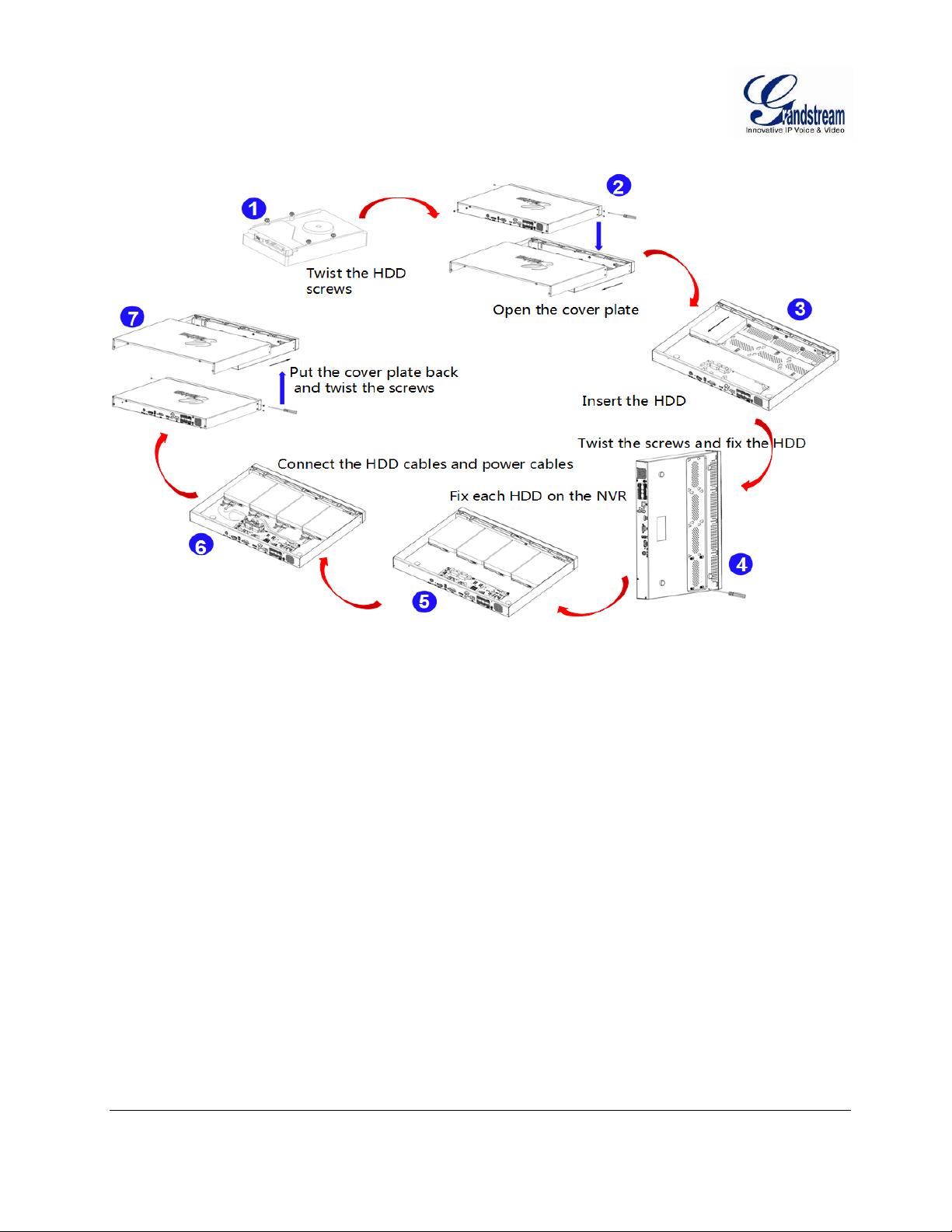
Figure 1: GVR3550 HDD Installation
Grandstream Networks, Inc. GVR3550 User Manual Page 14 of 120
Firmware Version 1.0.0.65 Last Updated: 10/2014
Page 15
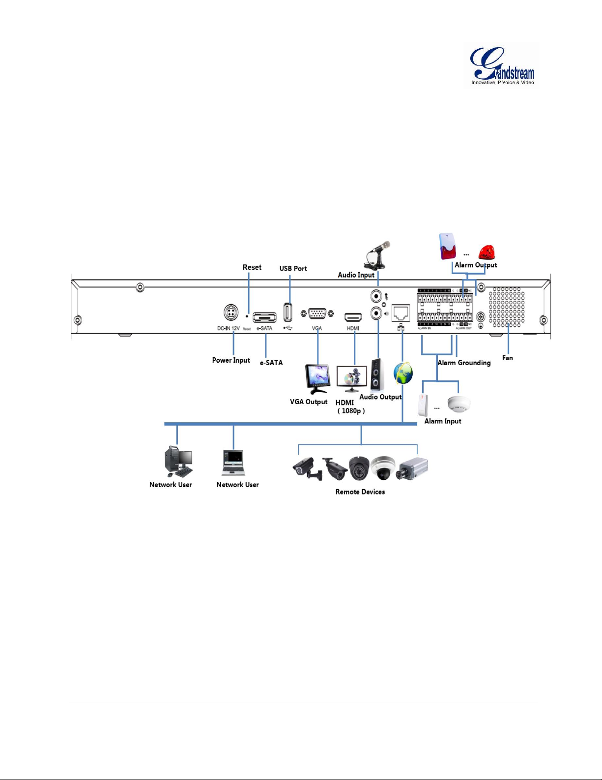
SYSTEM CONNECTION
Please connect the GVR3550 according to the following procedures:
1. Install the GVR3550 HDD by following the steps in chapter Installing HDD.
2. Plug in the cables and connect it to the display device interface.
3. Connect the mouse, keyboard, alarm input and output devices (optional).
4. Power up those optional devices before connecting power cable and power up the GVR3550.
5. Power up GVR3550, the power indicator will solid green; The HDD indicator will blink when it
works; The fn indicator will solid green if user presses function button.
Figure 2: GVR3550 System Connection Diagram
Grandstream Networks, Inc. GVR3550 User Manual Page 15 of 120
Firmware Version 1.0.0.65 Last Updated: 10/2014
Page 16
NETWOKR CONNECTION
NOTE:
The USB interface voltage on the front panel of the GVR3550 is a little higher than
the one on the rear panel, it is suggested that the USB interface on the rear panel
connect to mouse and keyboard while the one on the front panel connect to USB
storage devices.
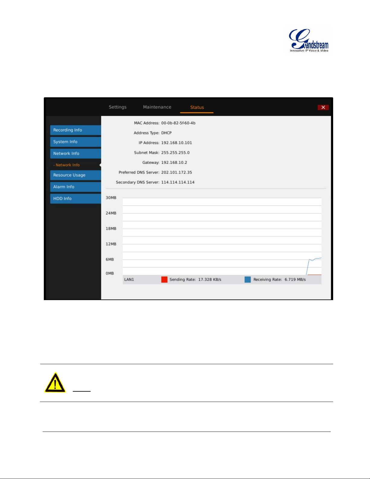
Users could login the Web page with the administrator account after plugging in the network cable to the
GVR3550, go to Main Menu ->Status-> Network Status to check the network status including IP address
and network send/receive rate as shown in Figure 3. For details, please refer to the chapter Network Info.
Figure 3: GVR3550 “Status” “Network Info” Page
EXTERNAL USB DEVICE
GVR3550 USB interface could be connected to mouse and keyboard, or a USB storage device.
Grandstream Networks, Inc. GVR3550 User Manual Page 16 of 120
Firmware Version 1.0.0.65 Last Updated: 10/2014
Page 17
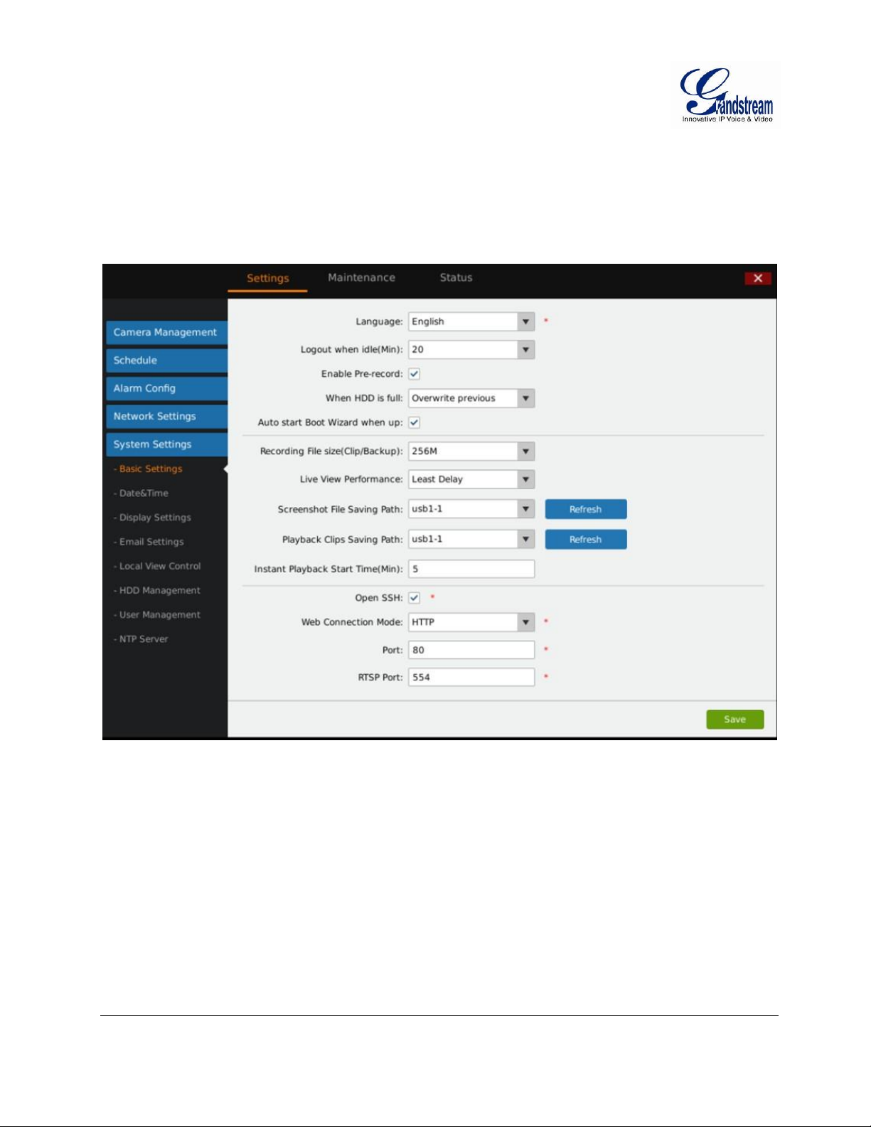
PLUG IN USB MOUSE/KEYBOARD
Users could check whether the mouse and keyboard installation is successful after plugging in them. The
mouse or keyboard might be not compatible with the GVR3550 if cannot be detected, please replace the
mouse or keyboard and try again.
Figure 4: GVR3550 System Setting Page
When the USB mouse is plugged into the GVR3550, users could make the following operations with the
mouse.
Single click the left mouse:
Enter a functional menu.
Change the dialog box or dynamic status.
Bring up the drop-down list when clicking the combo box.
Switch input methods in the input box, tap on the corresponding buttons on the soft keyboard to input
numbers.
Double click the left mouse:
Grandstream Networks, Inc. GVR3550 User Manual Page 17 of 120
Firmware Version 1.0.0.65 Last Updated: 10/2014
Page 18
Double click on one screen to switch to full screen in multi-screen view mode. Double click again to exit
NOTE:
If in a rare case that the mouse is not detected, the mouse might not compatible with
the GVR3550, please replace the mouse.
and go back to the previous multi-screen status.
Single click the right mouse:
Bring up the shortcut menu in real-time monitoring mode.
Do not save the menu options and exit the current menu, go back to the preview screen.
Scroll wheel:
Scroll up and down the list box.
Mouse Move.
Select one control or one entry below it with cursor.
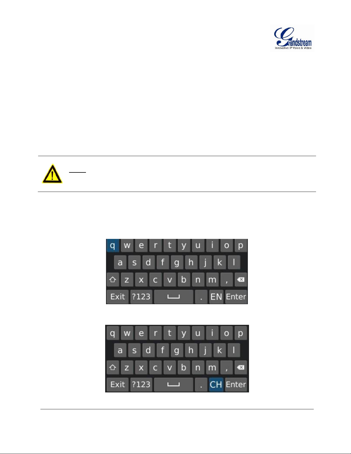
INPUT METHOD
The GVR3550 supports English and Chinese input methods; the input interface is as shown below.
Figure 5: GVR3550 Soft Keyboard – English Input Method
Figure 6: GVR3550 Soft Keyboard – Chinese Input Method
Grandstream Networks, Inc. GVR3550 User Manual Page 18 of 120
Firmware Version 1.0.0.65 Last Updated: 10/2014
Page 19
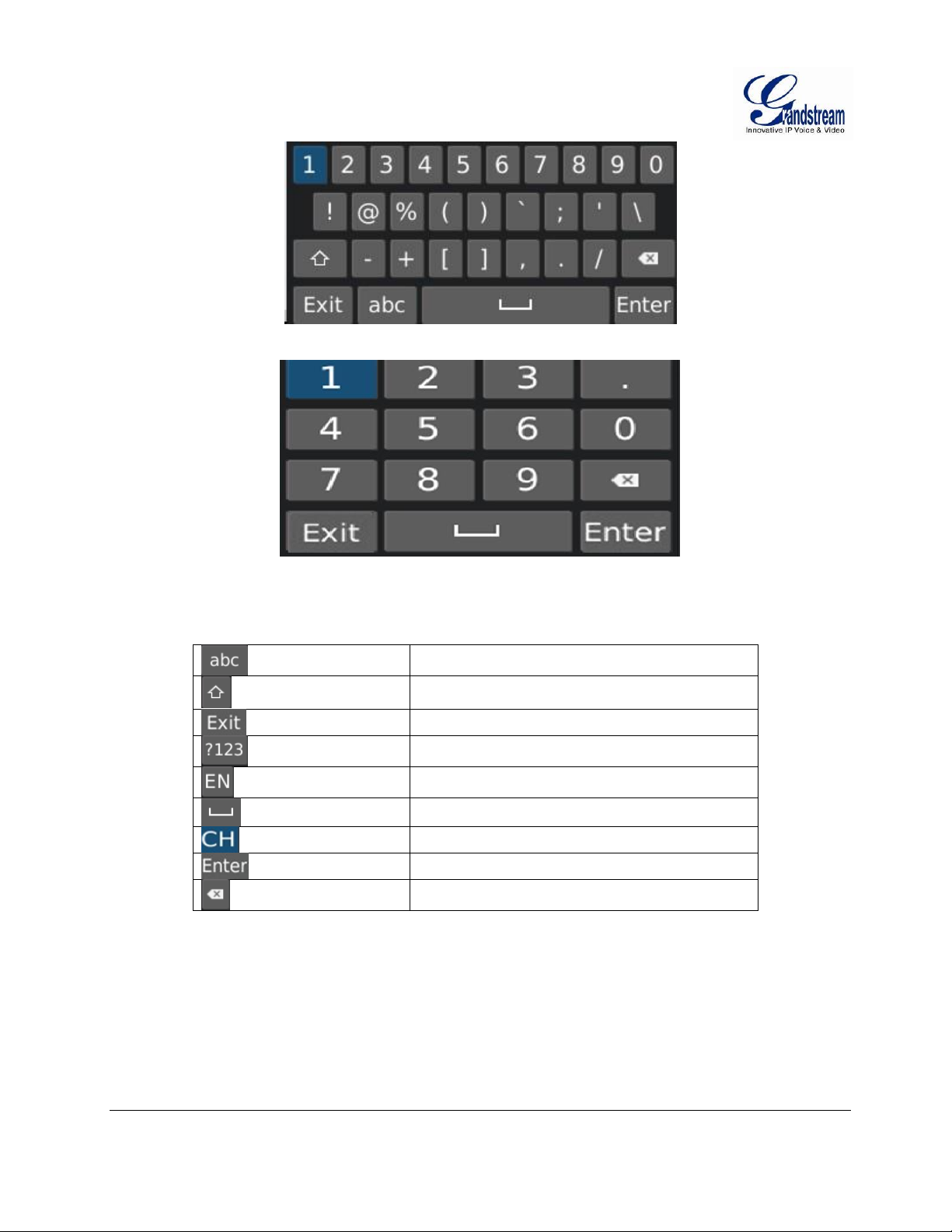
Input lowercase
Switch Caps Lock
Sequin
Switch to Numbers & Symbols
Switch to alphabet
Space
Switch to Chinese input method
Enter
Backspace
Figure 7: GVR3550 Soft Keyboard – Symbol and Number
Figure 8: GVR3550 Soft Keyboard – Numeric Keyboard
Table 3: GXV3550 Soft Keyboard Explanation:
PLUG IN USB STORAGE DEVICE
Users could click right mouse to check if there is "Uninstall" option in the menu after plugging in the USB
device correctly. The option means the USB device is normal for use. Users could also go to Settings>System Settings->Basic System Settings, click "Refresh" as shown in figure below to check the USB
device status.
Grandstream Networks, Inc. GVR3550 User Manual Page 19 of 120
Firmware Version 1.0.0.65 Last Updated: 10/2014
Page 20

INSTALLING eSATA
Plug in the eSATA cable to the corresponding interface on the rear panel of the GVR3550, power up
eSATA or electrify it with USB cable (according to eSATA specific situation).Users could go to Settings>System Settings->HDD Management to view details like HDD Space, Free Space, HDD Status, HDD
Type after installing eSATA. For details, please refer to the chapter HDD Management.
Figure 9: GVR3550 HDD Management Page
CONNECT HDMI MONITOR
Connect one end of the HDMI cable to the port on the rear panel of the GVR3550, and the other end to the
corresponding port of the HDMI monitor. Once powered up, one preview screen of the GVR3550 appears
on the HDMI monitor. GVR3550 can automatically adapt to HDMI monitor with 1080p and 720p
resolution.
CONNECT VGA MONITOR
Connect one end of the VGA cable to the port on the rear panel of the GVR3550, and the other end to the
corresponding port of the VGA monitor. Once powered up, the boot screen of the GVR3550 appears on the
VGA monitor.
Grandstream Networks, Inc. GVR3550 User Manual Page 20 of 120
Firmware Version 1.0.0.65 Last Updated: 10/2014
Page 21

NOTE:
VGA does not support automatic resolution matching.
There is only one valid output when connect to VGA and HDMI monitor the
same time. HDMI is valid while VGA is not by default. Users can also go to
System Settings->Display to set parameters like Screen resolution,
brightness, contrast, saturation and hue.
CONNECT ALARM DEVICE
Alarm input/output connection procedures are as follows:
1. Connect the alarm input device to the alarm input port.
2. Connect the alarm output device to the alarm output port.
3. Enter the GVR3550 main menu, set corresponding settings to alarm input/output on the Alarm Settings
page. Alarm serial number 1 corresponds to the first alarm input on the GVR3550 I / 0 port, the
following numbers keep to the same matching sequence. Set normally-opened alarm and normallyclosed alarm according to the corresponding high /low electrical when alarm.
4. Set alarm output on the Alarm Settings page. Alarm output 1 corresponds to the first alarm output; the
following numbers keep to the same matching sequence.
EXTERNAL INTERCOM DEVICE
GVR3550 support web paging and local paging:
1. Connect the audio-input device like microphone or pickups with RCA port to the audio input port on
the rear panel.
2. Connect the audio-output device like speaker or stereo with RCA port to the audio output port on the
rear panel. (The steps above ensure the GVR3550 could input or output audio)
3. Connect the microphone to the audio input of PC, the earphone or stereo to the audio output of PC.
Connect the audio input/output device to the compatible cameras.
Grandstream Networks, Inc. GVR3550 User Manual Page 21 of 120
Firmware Version 1.0.0.65 Last Updated: 10/2014
Page 22

PRODUCT OVERVIEW
Specification
Description
Video Recording
Supports synchronous 24 channels 720p (with 1280x720 resolution) record or 12
channels 1080p (with 1920x1080 resolution) record
Recording Rate
Supports up to 48 Mbps recording rate
Recording Mode
Supports continuous record, schedule record ,alarm record and manual record
Video Encoding
H.264 baseline, main or higher
Audio Encoding
G.711 a/u law
Live View
Up to 16 channels of VGA, 4 channels of 720p, or 2 channels of 1080p via HDMI or
VGA output
Playback
Supports synchronous local or remote 4 channels playback.
Trigger Event
Alarm
Trigger modes: manual alarm, schedule alarm, IPC alarm, I/O alarm, event alarm
and abnormal alarm
Intelligent
Retrieval
Intelligent retrieval modes: retrieval by Date & Time, motion detection
Total Storage
Up to 16TB internally with encryption; additional storage available via external
eSATA
RAID
Supports RAID 0 and RAID 1
Redundancy
Supports records backup to USB
QoS
Layer 2 QoS (802.1Q, 802.1p) and Layer 3 QoS (ToS, DiffServ, MPLS) (Layer 3
QoS coming soon)
Protocol
Supports HTTP, HTTPS, ONVIF protocol
Network Protocol
TCP/UDP, RTP/RTCP/RTSP, HTTP/HTTPS, ARP, ICMP, DNS, DDNS, DHCP
(client and server), NTP (client and server), SSH, PPPoE, LLDP (pending), 802.1X,
ONVIF 2.2
IP Camera
Supports all Grandstream GXV36xx series IPC or some ONVIF compatible IPCsl
Security Protocol
Supports HTTPS, 802.1x, SSH
GVR3550 SPECIFICATIONS
Table 4: GXV3550 Software Specifications:
Grandstream Networks, Inc. GVR3550 User Manual Page 22 of 120
Firmware Version 1.0.0.65 Last Updated: 10/2014
Page 23

Name
Description
Interface
1 HDMI interface; 1 VGA interface; 1 x 10/100/1000Mbps auto-sensing RJ45 port;
1 RCA Audio Input & Output interface
Alarm In
Terminal 16 inputs (NO/NC), Vin 2.5V~12V,Iin 2.5mA~30mA
Alarm Out
Terminal 2 outputs (Relay), 0.5A at 125 VAC; 2A at 30 VDC
UPS
UPS Management (pending)
USB Interface
Two 2.0 USB interfaces
eSATA
1 eSATA interface
LED Indicator
Power, LAN Link/Activity, Hard Drive Activity, fn
Remote Control
Supports IR remote control
RTC
Supports RTC
Internal HDD
Up to 4 3.5” SATA hard drives with maximum 16TB storage (HDD not included)
Universal Power
Supply
Input: 100~240V 50/60Hz; Output: 12V/5A 60W
Environmental
Operation: 0°C to 50°C
Storage: -20°C to 60°C (HDDs not included)
Humidity: 10% to 90% non-condensing
Installations
1U rack mount with front brackets
Compliance
FCC: Part 15 (CFR 47) Class B
FCC: Part 15, (CFR 47) Class B
CE: EN 55022, EN 55024, EN 61000-3-2, EN 61000-3-3, EN 60950
RCM: AS/NZS CISPR22, AS/NZS CISPR24, AS/NZS 60950
Comply with R & TTE, RoHS & WEEE
Table 5: GXV3550 Hardware Specifications:
Grandstream Networks, Inc. GVR3550 User Manual Page 23 of 120
Firmware Version 1.0.0.65 Last Updated: 10/2014
Page 24
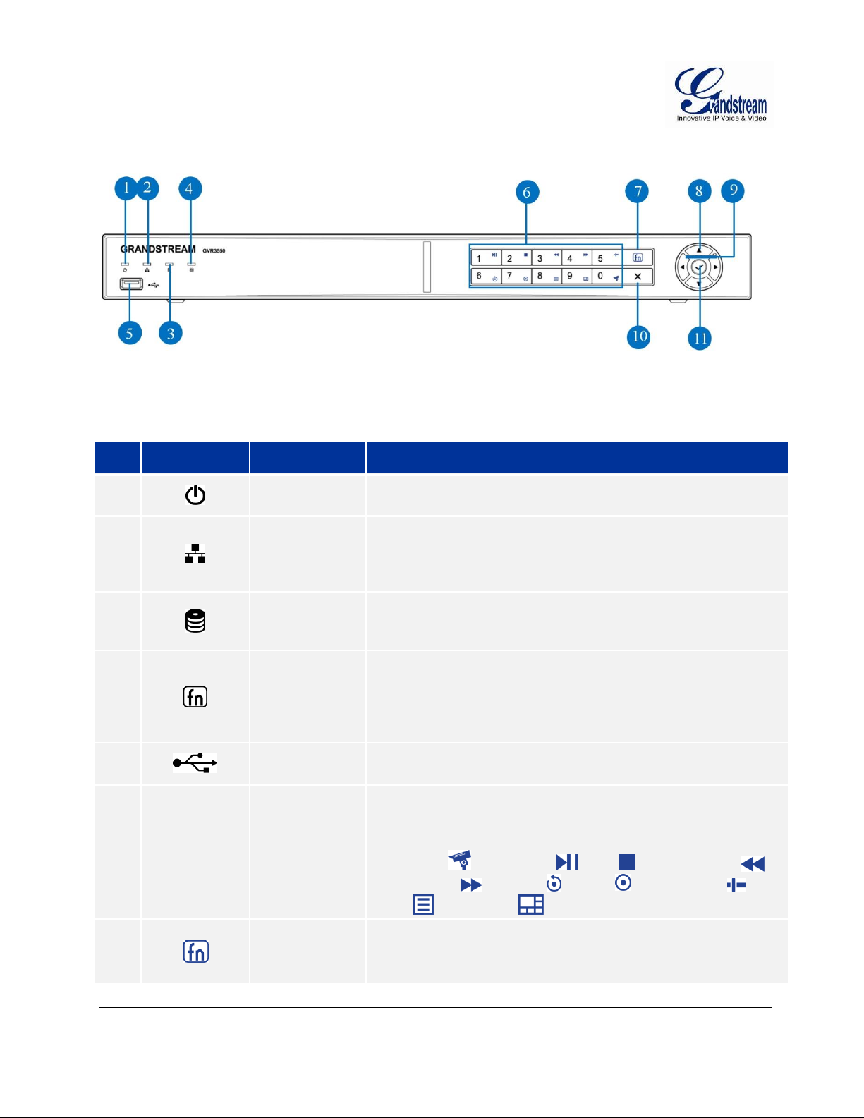
GVR3550 FRONT PANEL
#
Icon
Name
Explanation
1.
Power
indicator
Power indicator will solid Green when GVR powers up.
2.
Network
Indicator
When the network is abnormal or the GVR has no access to the
network, the indicator does not flicker when alarm; When the
network connection is normal the green indicator is normally on;
When transmitting data, the indicator flickers green.
3.
HDD
Indicator
The indicator will flicker Green if the HDD runs normally. If the
HDD capacity is full, GVR will dispaly a warning prompt on
screen.
4.
Status
Indicator
To indicate whether the numeric buttons features other functions.
When press the function button, the numeric buttons would
feature as function buttons. The indicator turns green when the
numeric buttons are in functional mode while in numeric mode
the indicator is dark.
5.
USB Interface
To connect to USB device like mouse, keyboard and USB flash
drive.
6.
Numeric /
Function
Buttons
To input numbers and switch preview.
When press the function button, the numeric buttons will be used
as function buttons.
Number 0-9 are corresponding to the following functions:
Enable PTZ , Start/Pause , Stop , Fast Backward ,
Fast Forward , Playback , Record , Single Frame ,
Menu , Multiscreen .
7.
Function
Button
To switch between numeric mode and function mode.
The function status indicator indicates the status of the function
button.
Figure 10: GVR3550 Front Panel
Table 6: GXV3550 Front Panel Explanation:
Grandstream Networks, Inc. GVR3550 User Manual Page 24 of 120
Firmware Version 1.0.0.65 Last Updated: 10/2014
Page 25

8.
Up and Down
Direction
Buttons
To switch among the activated controls or move up or down.
Revise settings, add or subtract numbers.
Auxiliary Function: Navigate the PTZ menu up or down.
9.
Left and Right
Direction
Buttons
To switch among the activated controls or move left or right.
Controls the progress bar when playback.
Auxiliary Function: Navigate the PTZ menu left or right.
10.
Cancel
Button
Back to the previous menu or cancel operation.
Back to real-time monitoring state when playback.
11.
Confirm
Button
Confirm.
Switch to the default button.
Enter menu.
Switch between check box and ON/OFF button.
Pause/Resume auto patrol in the auto patrol preview mode.
Grandstream Networks, Inc. GVR3550 User Manual Page 25 of 120
Firmware Version 1.0.0.65 Last Updated: 10/2014
Page 26
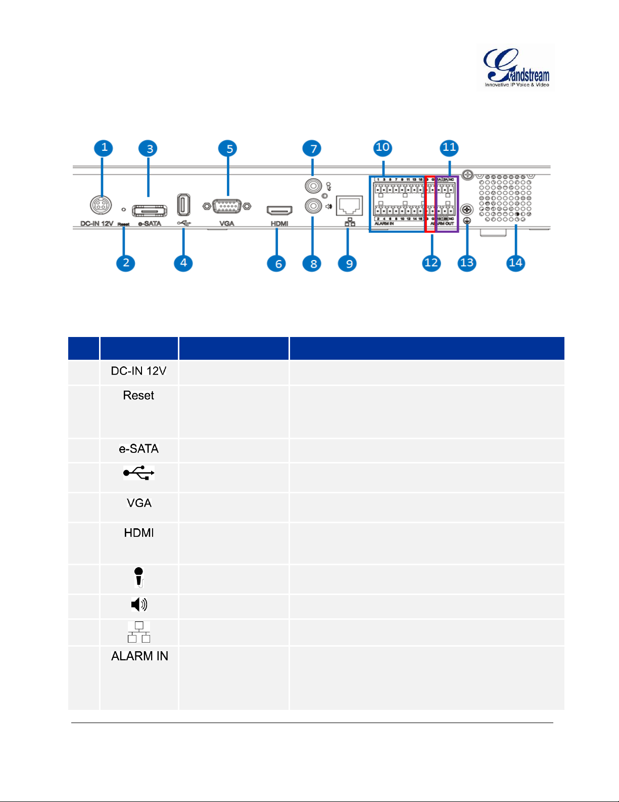
GVR3550 BACK PANEL
#
Icon
Name
Explanation
1
Power Input
Power interface, input 12V DC.
2
Reset Button
To reboot device or reset factory.
Long press for more than 10 seconds: factory reset.
Press when power on, reset when the GVR is
abnormal.
3
eSATA Interface
To connect eSATA device
4
USB Interface
To connect to USB devices, like mouse, keyboard and
USB flash drive.
5
VGA Output
Output analog video signal, connecting to a monitor to view
the video.
6
HDMI Output
HD audio/video output interface, transmit uncompressed
HD video and multi-camera audio data to the display
device with HDMI interface.
7
Audio Input
Audio input interface, receiving analog audio signal from
microphone and other devices.
8
Audio Output
Output analog audio signal to device like Speaker
9
Network Port
10M/100M/1000M adaptive Ethernet interface.
10
Alarm Input
1~16
16 alarm input interface, receiving binary signals of
external alarm like normally-closed alarm and normallyopen alarm.
When electrify the alarm input device with external power,
the device should be common-grounded with the GVR.
Figure 11: GVR3550 Back Panel
Table 7: GXV3550 Back Panel Explanation:
Grandstream Networks, Inc. GVR3550 User Manual Page 26 of 120
Firmware Version 1.0.0.65 Last Updated: 10/2014
Page 27
11
Alarm output
1~2:
2 sets alarm output interface, output alarm signal to the
external alarm device, power supply is required for external
alarm device.
12
--
Alarm Grounding
Public alarm input grounding interface
13
Grounding
Grounding
14
--
FAN
For heat dissipation
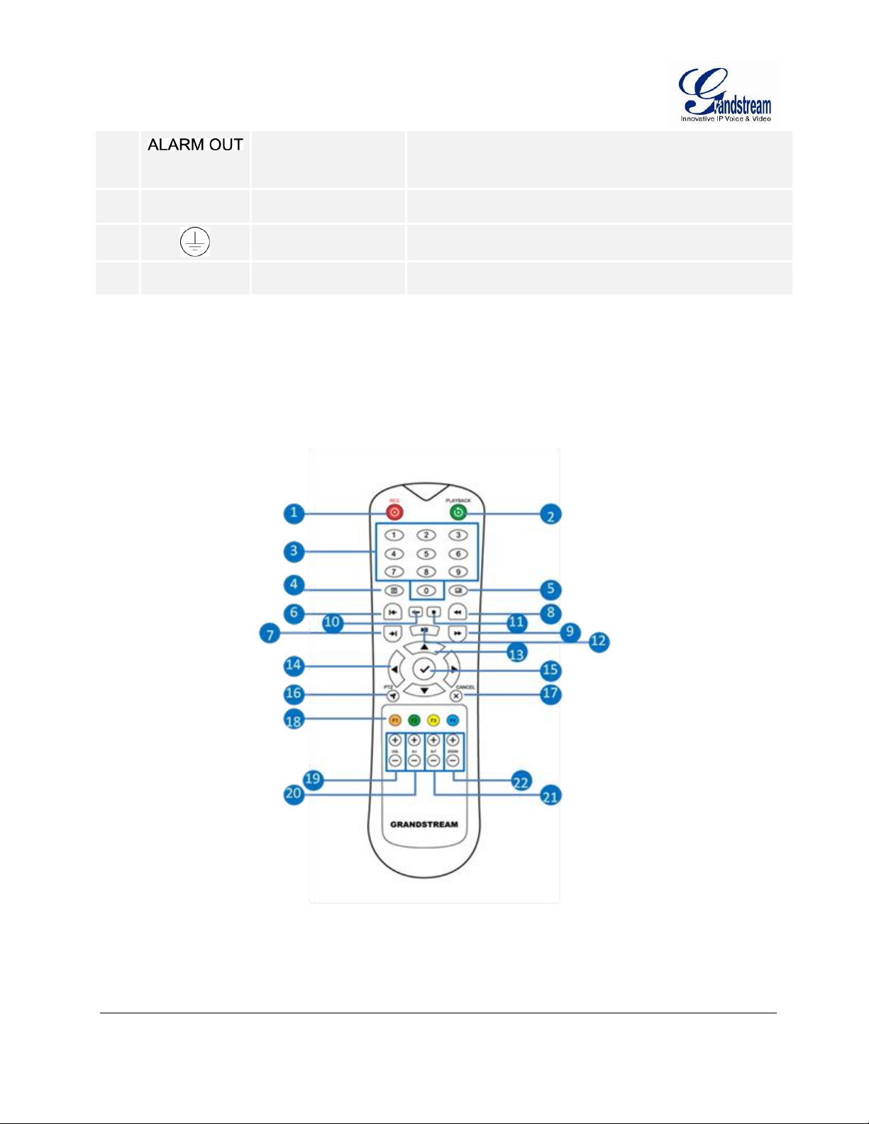
IR REMOTE CONTROL
Figure 12: IR Remote Control
Grandstream Networks, Inc. GVR3550 User Manual Page 27 of 120
Firmware Version 1.0.0.65 Last Updated: 10/2014
Page 28
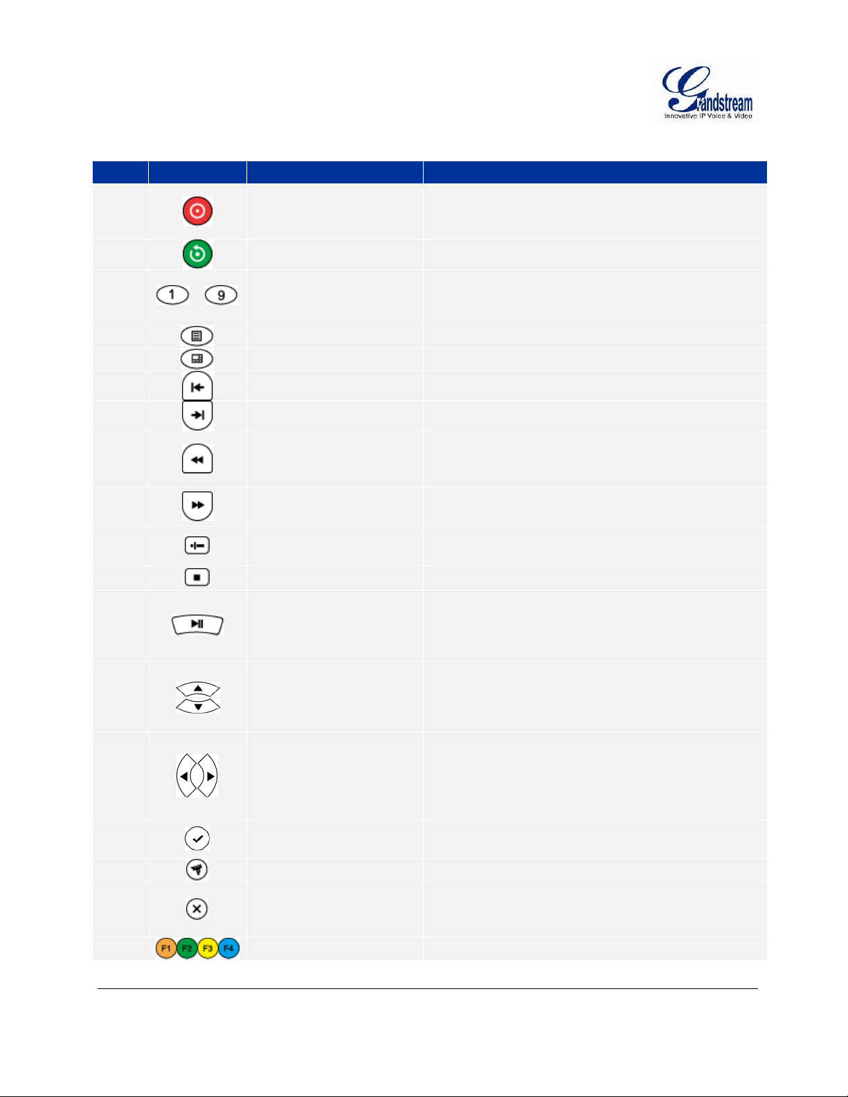
Table 8: GXV3550 Remote Control Key Explanation:
#
Icon
Name
Explanation
1
REC Button
Manual start/stop recording. Use REC button and the
direction buttons to select the camera to record in the
record control menu.
2
Playback Button
Enter playback screen
3
…
Numeric Buttons
Features the same function as the numeric buttons
on the front panel (Only numeric function) and switch
review screen.
4
MENU Button
Enter menu
5
Multiscreen Button
Switch the display to a single screen or multiscreen
6
Single-frame back Button
Single frame playback of the record
7
Single-frame Step Button
Single frame forward of the record
8
Fast Backward Button
Various fast backward and normal playback modes,
the speed would be displayed on the playback
screen
9
Fast Forward Button
Various fast forward and normal playback modes, the
speed would be displayed on the playback screen
10
Skip Button
Switch to skip mode. User SKIP button with the
UP&DOWN buttons to decide when to play records.
11
STOP Button
Stop playing recorded video。
12
PLAY/PAUSE Button
Press the button to playback when playback
pauses.
Press the button to pause playback when
playback.
13
UP & DOWN
Direction Buttons
Switch the activated controls to up or down.
Switch cameras to up or down when preview
Auxiliary function (e.g.: Control and operate the
PTZ menu).
14
LEFT & RIGHT
Direction Buttons
Switch the activated controls to left or right.
Switch cameras to left or right when preview.
Control the progress bar when playback record.
Auxiliary function (e.g.: Control and operate the
PTZ menu).
15
ENTER Button
Confirm operations.
Switch to the default button
16
PTZ Control Button
Enable/Disable PTZ Control
17
Cancel Button
Back to the upper level, menu or cancel operations
when pressing the function menu button (Close the
top-level page or controls).
18
Function Buttons 1-4
F1, F2, F3 and F4 Function buttons.
Grandstream Networks, Inc. GVR3550 User Manual Page 28 of 120
Firmware Version 1.0.0.65 Last Updated: 10/2014
Page 29

19
Vol Button +-
Adjust the volume of the cameras when preview or its
volume when play back record.
20
A-I Button +-
Adjust aperture at PTZ control
21
A-F Button +-
Adjust focus at PTZ control
22
Zoom Button +-
Electronic zoom adjustment at PTZ control.
Electronic zoom adjustment when one camera.
Playback record at full screen.
The correct way to use IR remote control: Batteries must be installed before use. Please aim the remote
control at the IR receiver on the GVR3550 then make operations. If the GVR3550 receives the control’s
command, you can use the control to manipulate the GVR3550. If failed, please check whether the
following reasons are the causes:
Check the battery polarities
Check whether the battery power
Check whether the remote sensor is obscured.
Check whether a fluorescent lamp is being used nearby.
If the remote still cannot function normally beyond the above situations, please change a remote and
try again, or contact the device provider.
Grandstream Networks, Inc. GVR3550 User Manual Page 29 of 120
Firmware Version 1.0.0.65 Last Updated: 10/2014
Page 30

LOCAL OPERATIONS
In this chapter, we take using the mouse as an example.
USING THE WIZARD
Users could use the wizard for basic configuration once started the GVR3550 to make it work properly.
1. Enter administrator password (The default is "Admin") to log in the GVR. Check to confirm whether to
enable the wizard next time boot up the unit.
2. Click on "Next" to access basic settings page to configure language and display time. Set time zone
and system time.
3. Click on "Next" to access network settings page to set up IP address, subnet mask and gateway.
4. Click on "Next" to access HDD management page to set up HDD array and HDD full strategy.
5. Click on "OK" to finish setup.
LOGIN
Input the username and password to login or click on the menu button in the lower left corner of the
page to login. The factory default username is "admin", the password is "admin". Users have to login
again if timeout without operations. Password change recommended after initial login.
After logging in the GVR3550 local page, users could click right mouse and then select any item in a popup menu to bring up the GVR3550 login page.
Grandstream Networks, Inc. GVR3550 User Manual Page 30 of 120
Firmware Version 1.0.0.65 Last Updated: 10/2014
Page 31

Figure 13: GVR3550 Local Login Page
LOCAL VIEW
The GVR3550 would directly enter live view screen after boots up, users could check the preview screen
without login but unable to make any operations. Only after logged in users could make basic view
operations and other setups.
Grandstream Networks, Inc. GVR3550 User Manual Page 31 of 120
Firmware Version 1.0.0.65 Last Updated: 10/2014
Page 32

Figure 14: GVR3550 Live View Page – Right Click Menu
VIEW STATUS
Preview camera status: The camera has not been added, camera preview, connecting the camera, camera
connection failed.
Grandstream Networks, Inc. GVR3550 User Manual Page 32 of 120
Firmware Version 1.0.0.65 Last Updated: 10/2014
Page 33

Table 9: GVR3550 Preview Status Explanation:
Icon
Name
Explanation
Motion Detection
Alarm
Alarm when detecting dynamic motion.
Camera Lens
Occlusion Alarm
Alarm in the corresponding camera when the remote camera is
obscured.
Missing Object
Alarm
Alarm in the corresponding camera according to the alarm settings if
the remote camera supports missing object alarm and local missing
object alarm has been configured before.
Foreign Object
Alarm
Alarm in the corresponding camera according to the alarm settings if
the remote camera supports missing object alarm once local foreign
object alarm has been configured before.
I/O Alarm
Alarm when the remote camera is connected to IO alarm device
according to the alarm settings.
Record
The monitoring camera is in record mode.
Add Camera
If there is no existing camera, click this button to quick enter the
camera settings page to add camera.
--
Camera View
Live view camera.
Camera
connection
Failed
Failed to connect the related IP Cameras.
Video Decoding
Failed
It may be caused by protocol not supported, too large resolution and
exceeded the decoding ability.
On the preview page, the record and alarm status of each camera could be distinguished by the tag on the
top right corner of each camera.
A dialog box will pop up in the center screen to prompt the users if there is an abnormal alarm, as shown in
figure below, the prompt box would disappear in 3 seconds.
Grandstream Networks, Inc. GVR3550 User Manual Page 33 of 120
Firmware Version 1.0.0.65 Last Updated: 10/2014
Page 34

Table 10: GVR3550 System Abnormal Alarm Screen Explanation:
#
Icon
Name
Explanation
1
Close Record
The camera is not recording now
Auto Record
The camera is in schedule record mode
Manual
Record
The camera is in manual record mode
2
Capture
The external storage devices (USB) need to be connected first. Users
could configure the save path and set it to default
3
Mute/Unmute
When the volume in on, if the remote camera is installed with audio
input device, users could listen in to the remote party
4
Start /Stop
Intercom
When the intercom in on, if the remote camera is installed with audio
output device, users could speak to the remote camera via local audio
input device.
5
PTZ Control
Click to enable PTZ control to configure PTZ preset, patrol and pattern
Icon
Name
Explanation
Disconnection
Alarm
Alarm when the network is disconnected.
HDD Empty
Alarm
Alarm when no HDD detected.
HDD Error Alarm
Alarm when HDD is abnormal.
HDD Full Alarm
Alarm when HDD is full.
IP Conflict Alarm
Alarm when detecting the IP address of another device is in conflict
with the GVR in the network.
BASIC VIEW OPERATION
Users could put the cursor on one camera screen if needs to make basic operations to a particular camera.
Click to bring up the menu bar as shown in Figure 15. Click the buttons on the menu bar to make
corresponding operations.
Figure 15: GVR3550 Basic View Operation
Table 11: GVR3550 Basic View Operation Explanation:
Grandstream Networks, Inc. GVR3550 User Manual Page 34 of 120
Firmware Version 1.0.0.65 Last Updated: 10/2014
Page 35

6
Switch to Full
Screen
Switch the current screen to full screen or double click to enter full
screen mode. Click or double click the screen to exit full screen.
7
Instant
Playback
Playback the record in the preset time. It will prompt "The selected
camera has no record "if has no existing record. Users could set the
preset time in Basic System Settings chapter
8
Image Config
Enter the corresponding setting page to adjust the current window
image.
9
Encode Config
Open interface to configure encoding parameters of IP Camera
NOTE:
Start intercom will unmute the camera the same time. Close the intercom to mute the
camera.
When start intercom of one camera, if another camera has enabled intercom or unmute, turn
off it first then start intercom of the current camera.
If one camera has enabled intercom or unmute, unmute another camera will close
intercom/unmute the previous camera automatically.
Grandstream Networks, Inc. GVR3550 User Manual Page 35 of 120
Firmware Version 1.0.0.65 Last Updated: 10/2014
Page 36

IMAGE CONFIG
Click on the image config button to bring up the dialogue box as shown in Figure 16.
Users could adjust brightness, contrast, saturation and hue by clicking the corresponding Plus/Minus icon
or click button to access editing mode.
Figure 16: GVR3550 Image Config Page
PTZ CONTROL
Click the PTZ control button to bring up the PTZ control interface, as shown in Figure 17 below.
Figure 17: GVR3550 PTZ Control Page
Grandstream Networks, Inc. GVR3550 User Manual Page 36 of 120
Firmware Version 1.0.0.65 Last Updated: 10/2014
Page 37

Table 12: GVR3550 PTZ Control Parameter Explanation:
#
Name
Explanation
1
PTZ Direction Control and
Reset Button
8 PTZ direction buttons to control the corresponding eight PTZ
directions, the reset button to restore PTZ direction to the
original position
2
Iris+
Increasing Iris
3
Focus+
Increasing the Focus
4
Zoom+
Increasing zoom. Only available in full screen mode.
5
Iris-
Reducing Iris
6
Focus-
Reducing the Focus
7
Zoom-
Reducing zoom. Only available in full screen mode.
8
Step
Step used to control PTZ controller moving speed, e.g.: Step 8
will be much faster at moving compared to Step 1. (The
number can be adjusted by mouse or front panel keypad)
9
More
Opening more PTZ Control parameters
10
PZT Control Selection
When set PTZ to preset, bring up preset setting interface
and operation panel below the screen.
When set PTZ to patrol, bring up patrol setting interface
and operation panel below the screen.
When set PTZ to pattern, bring up contrail setting interface
and operation panel below the screen
11
Exit
Click to exit the PTZ control interface directly
NOTE:
The GVR3550 only supports PTZ control with ONVIF Protocol, the IP camera should be
properly connected and the PTZ device should be configured. Please make sure theRS-485
cable between the PTZ decoder and the IP camera is connected correctly.
Grandstream Networks, Inc. GVR3550 User Manual Page 37 of 120
Firmware Version 1.0.0.65 Last Updated: 10/2014
Page 38

PRESET
When set PTZ to preset, users could add/delete/edit preset on the control panel below. The procedures are
shown in Figure 18.
Figure 18: GVR3550 PTZ Control Page – Preset
1. Adjust the remote camera position via the PTZ steering control.
2. Click on to add a new preset.
3. Enter the preset name in the input box or just use the default name.
4. Click the check button to save the preset, or click on on the right side of the preset to edit
the name.
5. Double click one preset with mouse (or press the OK button on the front panel, or press the ENTER
button on the remote control) to activate it.
6. Users could click below the preset control panel to delete the preset.
Grandstream Networks, Inc. GVR3550 User Manual Page 38 of 120
Firmware Version 1.0.0.65 Last Updated: 10/2014
Page 39

PATROL
When set PTZ to patrol, users could edit and use patrol path on the control panel. The factory default
setting is 4 empty patrol paths. See Figure 19.
Figure 19: GVR3550 PTZ Control Page – Patrol
1. Set PTZ to patrol.
2. Select the patrol path.
3. Set the residence time the patrol path stays at each preset.
4. Click on to add key point and set it as one preset. Users could click on in the lower right
corner of the panel to delete the preset.
5. Click on before the patrol path, when it turns to a triangle , the PTZ will cycle according to the
path. Click again to stop the patrol.
Grandstream Networks, Inc. GVR3550 User Manual Page 39 of 120
Firmware Version 1.0.0.65 Last Updated: 10/2014
Page 40

PATTERN
When set PTZ to pattern, users could edit and use pattern on the control panel. The factory default setting
is 3 empty patterns. See Figure 20.
Figure 20: GVR3550 PTZ Control Page – Pattern
1. Set PTZ control to pattern
2. Select the pattern name.
3. Click the "Start Record" button to adjust the remote camera pattern via the PTZ steering control.
4. Click the "Save Record" button save the pattern.
5. Click on before the pattern, when the button turns to a triangle , the PTZ will cycle according to
the pattern. Click again to stop PTZ movement.
Grandstream Networks, Inc. GVR3550 User Manual Page 40 of 120
Firmware Version 1.0.0.65 Last Updated: 10/2014
Page 41

RIGHT-CLICK
#
Name
Explanation
1
Record Playback
Enter Record Playback page
2
Main Menu
Enter device system setting page
3
Single Screen
Switch to one camera to preview
4
Four Screen
Switch to 4 screen: IMG One-to-Four, IMG Five-to-Eight, IMG Nineto-Twelve, IMG Thirteen-to-Sixteen, IMG Seventeen-to-Twenty, IMG
Twenty-one-to-Twenty-four
5
Six Screen
Switch to 6 screen: IMG One-to-Six, IMG Seven-to-Twelve, IMG
Thirteen-to-Eighteen, IMG Nineteen-to-Twenty-four
Click the right mouse to bring up the right-mouse menu, users could enter Record Playback or the Main
Menu, Start/Stop All record, Start/Stop Patrol, or unload the inserted USB device. The local screen can be
set to Single Screen and Four Screen, users need to set the specified cameras respectively.
When inserted USB storage device to export data, users could see the "Unload" option in the right-click
menu. Put the cursor on "Unload" and select "Unload USB" to unplug it once the data export is completed.
Figure 21: GVR3550 Right Click Mouse Menu
Table 13: GVR3550 Right Click Mouse Menu Parameter Explanation:
Grandstream Networks, Inc. GVR3550 User Manual Page 41 of 120
Firmware Version 1.0.0.65 Last Updated: 10/2014
Page 42

6
Nine Screen
Switch to 9 screen: IMG One-to-Nine, IMG Ten-to-Eighteen, IMG
Nineteen-to-Twenty-four
7
Sixteen Screen
Switch to 16 screen: IMG One-to-Sixteen, IMG Seventeen-toTwenty-four
8
Optimize System
Automatically adjust the camera connection protocol and secondary
stream resolution, bit rate, frame rate and related parameters.
Reboot after the completion
9
Start/Stop All Day
Record
Start All Manual Record. Once enabled, the menu item turns to "Stop
All Record". Click to stop all record including auto record
10
Start/Stop Patrol
Enable Patrol. Once enabled, the menu item turns to” Stop Patrol".
Click to stop patrol then stay on the current screen.
11
Camera Config
Quick access the camera settings
12
Unload
Unload the inserted USB device
NOTE:
Please go to Menu->System Settings->Local View Control to set Patrol Intervals
before apply Start Patrol.
Patrol would pause if users make any arbitrary operations in the process of patrol,
abort the operations to resume patrol.
SHORTCUT BUTTON
Click on the shortcut button in the lower left corner of the preview screen to bring up the shortcuts options
as shown in Figure 22. Users can enter the playback page or the main menu, login /logout or reboot the
unit.
Figure 22: GVR3550 View Page Shortcut Button Menu
Grandstream Networks, Inc. GVR3550 User Manual Page 42 of 120
Firmware Version 1.0.0.65 Last Updated: 10/2014
Page 43

LOCAL PLAYBACK
Click right mouse and select Record Playback to enter the playback page, as shown in Figure 23 below.
Users could make operations to record like Search, Playback, Tagging, Start Clipping, etc.
Figure 23: GVR3550 Record Playback Page
SEARCH RECORD
Users could search record by time and by tag.
SEARCH BY TIME
Select Record camera (up to 4 cameras) after selecting the record date, and then click the
"Search" button to search. The searched record would be displayed in the record status toolbar below the
playback page.
Grandstream Networks, Inc. GVR3550 User Manual Page 43 of 120
Firmware Version 1.0.0.65 Last Updated: 10/2014
Page 44

Figure 24: GVR3550 Record Playback – Record Status Toolbar Page
Icon
Name
Explanation
Select All
Display all types of recording
IO Alarm
IO alarm record file
IO Alarm (IPC)
Remote IO alarm record file (IP Camera)
Motion Detection
Motion detection record file
Missing Object Detection
Missing object detection record file
Foreign Object Detection
Foreign object detection record file
Camera Lens Occlusion
Camera occlusion record file
Video Loss
Video Loss file
Manual Record
Manual record file
Schedule Record
Schedule record file
There are color descriptions about the record status on the bottom. As Figure 24 shows, the priority of
color display is from left to right, from highest to lowest. (Except for "Select All").Select "by Time" and
click the check boxes of different colors to set whether to display the corresponding record .
Table 14: GVR3550 Recording Status Parameter Explanation:
Grandstream Networks, Inc. GVR3550 User Manual Page 44 of 120
Firmware Version 1.0.0.65 Last Updated: 10/2014
Page 45

SEARCH BY TAG
Select "by Tag" and input the keyword in the search query box, click "Search" to bring up the page as
shown in Figure 25 Click to playback.
Figure 25: GVR3550 Record Playback – Record Status Toolbar Page
Click "Tag Management" button to access the Tag Management page as shown in Figure 26, users could
edit or delete tag(s).
Figure 26: GVR3550 Tag Management Page
NOTE:
When HDD is full, the corresponding tag will be deleted
Grandstream Networks, Inc. GVR3550 User Manual Page 45 of 120
Firmware Version 1.0.0.65 Last Updated: 10/2014
Page 46

RECORD PLAYBACK
Icon
Name
Explanation
Manual Set Time
Click to enter the time setting page to set when to play the record.
Play/Pause
Play/pause record.
Stop
Stop playing record.
Rewind.
Play backward at certain speed, only available when in full screen.
Single Frame Rewind
Single frame play backward, only available when in full screen.
Single Frame Forward
Single frame play forward, only available when in full screen.
Speed Adjustment
To speed up the record, support 2 times, 4 times, 8 times and 16
time, 1 time, 1/2 time, 1/4 time, 1/8 time and 1/16 time fast forward.
Only available when in full screen.
Full screen
Select camera to enter full screen mode. Click the screen to bring up
the toolbar on the bottom of screen. The mouse located outside the
toolbar without any operations in three seconds would be hidden
automatically.
Capture
Snapshot the current screen and save the image to the external
storage device. If the capture failed, a prompt will be shown as in
Figure 28. Please insert the USB device then go to Main Menu>System Settings->Basic System Settings to set the save path
Volume
Click the button to bring up the volume control bar, drag it to adjust
the volume. Click the button again to close the control bar.
Tagging
Click the button to bring up the tagging setting page as shown in
Figure 29. Fill in the "Tag Name" input box and then click the
"Save" button.
1 Window.
Click a screen to display.
GVR3550 support synchronous 4 channels playback, users can specify the camera and playback date, or
make operations like Rewind, Single Frame Rewind/ Forward, Full Screen/Cancel Full Screen, Capture,
Lock Record, Tagging, lock Record, etc.
The playback toolbar is shown in Figure 27.
Figure 27: GVR3550 Record Playback Toolbar
Table 15: GXV3550 Record Playback Toolbar Explanation:
Grandstream Networks, Inc. GVR3550 User Manual Page 46 of 120
Firmware Version 1.0.0.65 Last Updated: 10/2014
Page 47

4 Window.
Click to enter 4 window .
Get Locked Recording.
Click the button to enter Locked Recording page as shown in Figure
30. Users could view all records and the locked records on certain
day. Click on to lock record and the locked record is labeled
with icon , click on to unlock the record. Users could also
click on the playback button to playback the record.
Start Clipping
Click the button to set the play time as start clipping time.
End Clipping.
Click the button to set the play time as end clipping time.
Download Clippings
Click the button to bring up the record save path Setting page as
shown in Figure 31 below. Click on the "Save" button to download
record after setting the path.
Figure 28: GVR3550 Save Snapshot Failed Prompt
Figure 29: GVR3550 Tagging Management
Grandstream Networks, Inc. GVR3550 User Manual Page 47 of 120
Firmware Version 1.0.0.65 Last Updated: 10/2014
Page 48

Figure 30: GVR3550 Locked Recording Management Page
Figure 31: GVR3550 Recording Save Path Setting Page
NOTE:
The configured default path would be invalid if the external storage device is changed, the
corresponding failure prompt would pop up if users click the "Capture" or "Download" button.
Users could go to Main Menu->System Settings->Basic System Settings to set the default path to
save snapshots and download file.
Please do not disconnect the USB device when downloading the clippings files or it may cause
download failure or error.
Users could click to set time range: 3 hours, 6 hours or 12 hours. Click one time slot to
replay the record.
Click the Record File with time bar can start playback video recording at that time frame.
Grandstream Networks, Inc. GVR3550 User Manual Page 48 of 120
Firmware Version 1.0.0.65 Last Updated: 10/2014
Page 49

MAIN MENU
Right click the mouse to enter the GVR3550 main menu page, see Figure 32.
Figure 32: GVR3550 Main Menu Page
The configuration items are varied according to different user permissions. Administrator users can make
operations like System Settings, Maintenance.
Grandstream Networks, Inc. GVR3550 User Manual Page 49 of 120
Firmware Version 1.0.0.65 Last Updated: 10/2014
Page 50

CAMERA MANAGEMENT
Camera management includes Search& Configure, Record Mode Config, Camera Event Settings and
Encoding Config.
SEARCH/CONFIGURE CAMERA
Click on “Search Camera" to search out all available cameras within the same LAN as shown in Figure 33
below.
Figure 33: GVR3550 Camera Management Setting Page
Tick the camera and click on "Add" button to add it to the camera list.
If unable to search out the camera you need automatically, users could manual add the camera to the
camera list. See Figure 34 below.
Grandstream Networks, Inc. GVR3550 User Manual Page 50 of 120
Firmware Version 1.0.0.65 Last Updated: 10/2014
Page 51

Figure 34: GVR3550 Manual Add Camera Page
Parameter
Explanation
Camera
Set the camera No., existing camera number cannot be changed.
Protocol
Supports the Grandstream series cameras and cameras compatible with ONVIF
protocol
Protocol (IP)
Set the protocol to TCP or UDP
IP Address
Set the IP address of the remote IP Camera
Port
Set the port number of the remote IP Camera
Username
Set the username to connect the remote IPC. The default is "admin"
Password
Set the password to connect the remote IPC. The default is "admin"
Table 16: GVR3550 Camera Parameter Setting Explanation:
NOTE:
When trying to connect to the remote IPC, the username and password the GVR use are both
"admin" or null by default. If the username and password are not default ones, the connection may
fail. Please manual modify the remote IPC username and password.
Grandstream Networks, Inc. GVR3550 User Manual Page 51 of 120
Firmware Version 1.0.0.65 Last Updated: 10/2014
Page 52

RECORD MODE CONFIG
All day record Status:
Enable all cameras to record.
Auto Record Status:
Enable record via the camera.
Close Record Status:
Disable record via the current camera.
Record Mode Configuration page is as shown in Figure 35 below, users could click one camera to set
Close Record, All Day Record and Schedule Record.
Figure 35: GVR3550 Record Mode Config Page
When set to "Schedule", users should select schedule in the drop-down list .Tap on to add new schedule;
Or tap on "Close for All" or "All Day for All" to set cameras.
Grandstream Networks, Inc. GVR3550 User Manual Page 52 of 120
Firmware Version 1.0.0.65 Last Updated: 10/2014
Page 53

Figure 36: GVR3550 Record Mode Setting Page
CAMERA EVENT SETTINGS
Camera event settings page is as shown in Figure 37 below, users could set different Alarm type to each
camera.
Figure 37: GVR3550 Camera Event Setting Page
Grandstream Networks, Inc. GVR3550 User Manual Page 53 of 120
Firmware Version 1.0.0.65 Last Updated: 10/2014
Page 54

Parameter
Explanation
Camera
Select the camera user would like to configure
Event Type
Motion Detection, Camera Lens Occlusion, Signal Loss, IPC External Alarm,
Missing Object Detection, Foreign Object Detection.
Alarm Enable
Tick to enable/unable alarm.
Alarm Schedule
Select schedule in the drop-down list .
Region Config
Set detection area to IPC with Motion Detection, Missing Object Detection and
Foreign Object Detection function. Users could set up to 16 detection areas.
Move the mouse to add areas and click on X in the upper right corner of the area
to delete it. Double click or right click the mouse to save the area and exit.
PTZ Linkage Config
Only available to IPC with PTZ linkage function. For different IPC and camera
alarm event, users could set various alarm action: Screen Prompt, Beep, HDMI
Alarm, Send Mail, Alarm Output, Alarm Delay(s).Or copy the alarm action to
other cameras.
Alarm Action
Set different alarm mode.
Parameter
Explanation
Screen Remind
Click to send alarm to display screen
Beeping
Click to beeping when alarm triggered
HDMI Alarm
Click to send alarm to GVR3550 connected HDMI display device
Email Notification
Click to send email to configured email. Email Configuration:
Main Menu Settings System Settings Email Settings
IP Camera
Click to select related alarm IP Cameras
Record Delay (Second)
Configure the time for alarm recording
Alarm Output
Click to select Alarm Output
Alarm Delay (Second)
Configure Alarm Delay Timer (in Second)
Copy to other IPC
Click to copy the alarm configuration to other IP cameras.
Table 17: GVR3550 Camera Events Settings parameters Explanation
Table 18: GVR3550 Camera Alarm Parameter Explanation:
Grandstream Networks, Inc. GVR3550 User Manual Page 54 of 120
Firmware Version 1.0.0.65 Last Updated: 10/2014
Page 55

ENCODING CONFIG
Parameter
Explanation
Camera Selection
Select a camera to configure codec configuration. It will display the camera’s IP and
model after selecting each camera.
Camera Name
Manual enter the camera’s name.
Display Time
Select if display the IPC’s time on Live View window.
Display Camera Name
Select if display the IPC’s name on Live View window.
Encoding Config page is as shown in Figure 38 below, users could configure camera's name and stream.
There are two streams. One is primary stream that is used for Play Black, another is secondary stream
which is used for Live View.
Figure 38: GVR3550 Encoding Config Page
Table 19: GVR3550 Encoding Config parameter Explanation:
Grandstream Networks, Inc. GVR3550 User Manual Page 55 of 120
Firmware Version 1.0.0.65 Last Updated: 10/2014
Page 56

Position
Select position to Top-Left or Bottom-Left for displaying IPC’s name and time on
live view.
Audio Recording
Set audio recording.
Primary Stream
Primary stream is used for Play Black.
Secondary Stream
Secondary Stream is used for Live View.
Video Codec
Select the Codec for each IPC. Beta version just supports H.264.
Resolution
Configure the resolution for each IPC. The Primary Stream resolution can’t support
more than 1920*1080P. The Secondary Stream resolution can’s support more than
640*480P (VGA).
Bit Rate Control
Set the Bit Rate Control to CBR or VBR.
Image Quality
Set the Image Quality, if the Bit Rate Control sets to VBR. It has 5 standards: Very
High, High, Normal, Low, Very Low.
Bit Rate (kpbs)
Set the different Bit Rate for IPC. Bit Rate can change the image quality, the more
bit rate the better image quality. The range for bit rate is from 256~8192Kbps。
Frame Rate(fps)
Set frame rate. The range is from 1~30fps。
i - frame interval
Set the video i-frame interval. The range is from 1~100s.
Grandstream Networks, Inc. GVR3550 User Manual Page 56 of 120
Firmware Version 1.0.0.65 Last Updated: 10/2014
Page 57

SCHEDULE CONFIG
Figure 39: GVR3550 Add New Schedule Page
Schedule on the weekly basis: at least set one period and users could set up to 16 periods. See Figure 39.
Grandstream Networks, Inc. GVR3550 User Manual Page 57 of 120
Firmware Version 1.0.0.65 Last Updated: 10/2014
Page 58

Figure 40: GVR3550 Schedule Config - Add New Schedule - Page
Grandstream Networks, Inc. GVR3550 User Manual Page 58 of 120
Firmware Version 1.0.0.65 Last Updated: 10/2014
Page 59

Users could edit, modify, delete schedule in the schedule list.
Click to view the schedule details as shown in Figure 41.
Figure 41: GVR3550 Schedule Details Page
Click to bring up the schedule editing page
Grandstream Networks, Inc. GVR3550 User Manual Page 59 of 120
Firmware Version 1.0.0.65 Last Updated: 10/2014
Page 60

HOLIDAY CONFIG
Users could add new holiday, manage schedule record, and alarm event of each camera. Users could add
up to 16 holidays. See Figure 42 below.
Figure 42: GVR3550 Holiday Config Page
Grandstream Networks, Inc. GVR3550 User Manual Page 60 of 120
Firmware Version 1.0.0.65 Last Updated: 10/2014
Page 61

Click "New Holiday" to bring up the page as shown in Figure 43 below. Users could custom holiday name.
Figure 43: GVR3550 Add New Holiday Page
Set holiday starting time and end time. Users could add up to 32 periods. See Figure 44 below:
Figure 44: GVR3550 Add New Holiday Editing Page
Grandstream Networks, Inc. GVR3550 User Manual Page 61 of 120
Firmware Version 1.0.0.65 Last Updated: 10/2014
Page 62

Users could edit, modify, delete schedule in the holiday list.
Click to view the holiday details as shown in Figure 45.
Figure 45: GVR3550 Holiday Details Page
Click to bring up the holiday editing page
ALARM CONFIG
The GVR3550 supports up to 16 channels alarm input and 2 channels alarm output. Please refer to the
chapter Connect Alarm Device to connect the output and input devices.
(IO) ALARM CONFIG
Users could set different alarm type to each corresponding camera, see Figure 46.
Grandstream Networks, Inc. GVR3550 User Manual Page 62 of 120
Firmware Version 1.0.0.65 Last Updated: 10/2014
Page 63

Parameter
Explanation
Input Port
Select the input port No. Click to select the port No. of alarm input.
Event Type
Select the event type like Input Alarm.
Alarm Enable
Tick to enable/disable the alarm.
Alarm Status
Set the alarm status. Normally Open (default) and Normally Close are two
available options. Please choose the status according to your alarm type. Restart
to make changes take effect.
Port Name
Enter the port name of the alarm input to distinguish different input ports.
Alarm Schedule
Select alarm schedule in the drop-down list. If there is no existing schedule,
users could click to add new schedule and enter the setting page to
configure. See Figure 47 below.
Figure 46: GVR3550 I/O Alarm Config Page
Table 20: GVR3550 IO Alarm Config Parameter Explanation:
Grandstream Networks, Inc. GVR3550 User Manual Page 63 of 120
Firmware Version 1.0.0.65 Last Updated: 10/2014
Page 64

Figure 47: GVR3550 I/O Alarm Config – Add New Schedule - Page
Users could set various alarm actions according to different alarm input such as Screen Prompt, Beeper,
HDMI Alarm, Send Email, or Copy Alarm to Other Camera. The Parameters settings are the same in
chapter Camera Event Settings.
Grandstream Networks, Inc. GVR3550 User Manual Page 64 of 120
Firmware Version 1.0.0.65 Last Updated: 10/2014
Page 65

ABNORMAL ALARM CONFIG
Parameter
Explanation
Disconnection Alarm
Alarm when detecting no cable access
HDD Empty Alarm
Alarm when detectng without HDD access
HDD Full Alarm
Alarm when HDD is fuill
HDD Error Alarm
Alarm when detecting HDD error
IP Conflict Alarm
Alarm when the IP address is conflict with the GVR address
Abnormal Alarm Config includes Disconnection Alarm, HDD Empty Alarm, HDD Full Alarm, HDD Error
Alarm and IP Conflict Alarm. See Figure 48 below. Users can set the alarm actions after selecting the
corresponding alarms.
Figure 48: GVR3550 Abnormal Alarm Config Page
Table 21: GVR3550 Abnormal Alarm Parameter Explanation:
Users could set various alarm actions like Screen Prompt, Beeper, HDMI Alarm, Send Email, or Copy
Alarm to Other Camera. The Parameters settings are the same in chapter Camera Event Settings.
Grandstream Networks, Inc. GVR3550 User Manual Page 65 of 120
Firmware Version 1.0.0.65 Last Updated: 10/2014
Page 66

NETWORK SETTINGS
Network Settings includes Basic Settings and Advanced Settings. Users could easily realize network
connection and ensure network security.
BASIC SETTINGS
Basic Settings page is shown in Figure 49 below, users can choose to obtain IPv4 address automatically or
manual set static IP address or use PPPoE. The GVR3550 is available only when network setup is correct.
Figure 49: GVR3550 Network Settings – Basic Setting Page
Grandstream Networks, Inc. GVR3550 User Manual Page 66 of 120
Firmware Version 1.0.0.65 Last Updated: 10/2014
Page 67

Table 22: GVR3550 Basic Network Parameter Explanation:
Parameter
Explanation
DHCP
Obtain IPV4 address from the DHCP server automatically
Static IP
Set static network parameters
IP Address
Manual enter the IPV4 address
Subnet Mask
Manual enter the IPV4 subnet mask
Gateway
Manual enter the IPV4 default gateway address
Preferred DNS
Manual enter the preferred DNS server address
Secondary DNS
Manual enter the secondary DNS server address
MTU (Byte)
Enter MTU (Maximum Transmission Unit), the maximum data package that can be
transmitted on the network. If the GVR MTU is larger than the one of the gateway,
the lager one will be split for transmission. Please confirm the MTU value of your
gateway before set
PPPoE
Tick to set static network parameters
Username
Manual enter the username provided by the network vendor
Password
Manual enter the password provided by the network vendor
Grandstream Networks, Inc. GVR3550 User Manual Page 67 of 120
Firmware Version 1.0.0.65 Last Updated: 10/2014
Page 68

ADVANCED SETTINGS
Advanced Settings page is shown in Figure 50. Users can set DDNS, UPnP and DHCP.
Figure 50: GVR3550 Network Settings – Advanced Settings Page
ENABLE DDNS
Enable DDNS to access the GVR via the domain name if already enabled PPPoE connection to the
internet, with this way can effectively solve the problem brought by access GVR with dynamic IP.
Select the proper DDNS type in the drop-down list and input the correct domain name, username and
password to complete the DDNS settings.
ENABLE UPnP
The full name of UPnP is Universal plug-in and Play, enable NAT of UPnP can realize auto port mapping
thus allows external computer to access intranet to enhance network efficiency.
After ticking "Enable UPnP", users can click to set the external port No., as shown in Figure 51 below.
Grandstream Networks, Inc. GVR3550 User Manual Page 68 of 120
Firmware Version 1.0.0.65 Last Updated: 10/2014
Page 69

Figure 51: GVR3550 Specify UPnP External Port Page
When the port status displays "Active", it indicates the successful connection of the GVR and the router and
the parameters have taken effect.
ENABLE DHCP
GVR3550 could allocate dynamic IP address to other devices within the same LAN. Follow the procedures
below to set:
1. Tick "Enable DHCP Server";
2. Input the assignable IP address.
3. Input Lease Time;
4. Set DNS server address and the secondary DNS server address.
Grandstream Networks, Inc. GVR3550 User Manual Page 69 of 120
Firmware Version 1.0.0.65 Last Updated: 10/2014
Page 70

SYSTEM SETTINGS
System Settings includes 8 options like Basic Settings, Display Settings, Local View Control, HDD
Management, etc.
BASIC SETTINGS
Basic Settings page is shown in Figure 52 below, users could set Recording File Size, Live View
Performance, language, Time Zone, etc.
Figure 52: GVR3550 System Settings Page – Basic Settings Page
Grandstream Networks, Inc. GVR3550 User Manual Page 70 of 120
Firmware Version 1.0.0.65 Last Updated: 10/2014
Page 71

Table 23: GVR3550 Basic System Setting Parameter Explanation:
Parameter
Explanation
Language
Set the language to English or Chinese
Logout when
idle(Min)
Set the logout time when timeout. If logout, users need to login again to make
operations except preview.
Enable Pre-record(s)
Set pre-record mode. Once enabled, users could view the record images a few
seconds before alarm in alarm event
When HDD Full
Set the record policy when HDD is full. "Overwrite Previous" means the new
record will overwrite the earliest ones when HDD is full of records. The default
setting is "Stop Record"
Auto start Boot
Wizard when up
Set whether to enable wizard when boot up. Once ticked, the wizard will pop up
for installation
Recording File
size(Clip/Backup)
The file size of recording (Clips/Backups).Users could choose 256M or 512M.
Default is 256M.
Live View
Performance
Set the view performance to Least Delay, Best Fluency and Balanced. Least delay
emphasizes the fluency of the record while best fluency emphasizes the real-time
of the recording. The default setting is "Least Delay"
Screenshot File
Saving Path
Set the default path to save the screenshot file when preview and playback
Playback Clips
Saving Path
Set the default path to save the clipping file when playback
Instant Playback
Start Time(Min)
Set the start time for instant playback. The default is 5 minutes
Open SSH
Set whether to open SSH
Web Connection
Mode
Set the web connection mode to HTTP or HTTPS, the default is HTTP
Port
Set the port No. of web connection, the default is 80.
RTSP Port
Set the port number of RTSP, the default is 554.
Grandstream Networks, Inc. GVR3550 User Manual Page 71 of 120
Firmware Version 1.0.0.65 Last Updated: 10/2014
Page 72

DATE&TIME
Parameter
Explanation
Set the time
Users could manual set the time, obtain time from the NTP server automatically
Manually
Manual set time
Obtain Automatically
Obtain time automatically from configured NTP server
Synchronize IPC time
Synchronize the GVR time to the connected IP cameras
NTP Server Address
Users could manual set the time or obtain time from the NTP server automatically
Time Zone
Manual set the time zone.
Manual set time
Manual set the system time.
Users could set system time. See Figure 53 below.
Figure 53: GVR3550 System Settings Page – Date & Time
Table 24: GVR3550 Basic System Setting – Date & Time Parameter Explanation:
Grandstream Networks, Inc. GVR3550 User Manual Page 72 of 120
Firmware Version 1.0.0.65 Last Updated: 10/2014
Page 73

Parameter
Explanation
Output mode
selection
Users could select output mode: Auto, VGA, HDMI.
VGA not support automatic resolution matching.
Both VGA/HDMI connected only HDMI is in effective (default HDMI).
Dual Output mode need configured to display VGA and HDMI simultaneously.
Maximum resolution of 1080p for HDMI or VGA could be configured
Brightness
Set the GVR brightness. The reference range is 0~100
Contrast
Set the GVR contrast. The reference range is 0~100
Saturation
Set the GVR saturation. The reference range is 0~100
Hue
Set the GVR saturation. The reference range is 0~100
DISPLAY SETTINGS
Users could set output mode and adjust output value like Brightness, Contrast, Saturation, Hue of the
connected display device. See picture 54 below.
Figure 54: GVR3550 System Settings Page – Display Settings
Table 25: GVR3550 Basic System Setting – Display Parameter Explanation:
Grandstream Networks, Inc. GVR3550 User Manual Page 73 of 120
Firmware Version 1.0.0.65 Last Updated: 10/2014
Page 74

EMAIL SETTINGS
The GVR3550 could end Email when triggered alarm, the procedures are as follows:
Figure 55: GVR3550 System Settings Page – Email Settings
1. Set SMTP server address;
2. Input the display name, sender address, username and password;
3. Set receiver address. The GVR3550 could set up to 3 receiver addresses. Users could send mails to
different receivers;
4. Set mail send interval. One alarm only sends one email in the interval;
5. Set mail subject and template. Users could use default ones or custom them.
Grandstream Networks, Inc. GVR3550 User Manual Page 74 of 120
Firmware Version 1.0.0.65 Last Updated: 10/2014
Page 75

Table 26: GVR3550 Email Template Parameter Explanation:
#
Key Word
Explanation
1
$name
Name of Alarm
2
$time
Time of Alarm Triggered
3
$channel
Channel number of Alarmed IP Camera
4
$mac
MAC address of GVR3550
5
$ip
IP address of GVR3550
LOCAL VIEW CONTROL
Local View Control is to set camera and the patrol interval, as shown in Figure 56 below.
Figure 56: GVR3550 System Settings Page – Local View Control
The connected camera name will be displayed on the left list. Click on to access the camera page and
tick before the camera name to map the corresponding camera.
Grandstream Networks, Inc. GVR3550 User Manual Page 75 of 120
Firmware Version 1.0.0.65 Last Updated: 10/2014
Page 76

Figure 57: GVR3550 Local View Control – Apply Camera
HDD MANAGEMENT
HDD Management page is shown in Figure 58 below. Users could view each HDD storage status or format
HDD, erase data, configure attribution, etc.
Figure 58: GVR3550 System Settings Page – HDD Management
Grandstream Networks, Inc. GVR3550 User Manual Page 76 of 120
Firmware Version 1.0.0.65 Last Updated: 10/2014
Page 77

Add New Volume:
Access the detail page to set volume
Delete:
Delete existing volume. Users could delete the existing volume, please
consider carefully before apply. Once deleted, the volume data will be all
erased and could not be restored.
Add New Volume page is shown below.
Figure 59: GVR3550 HDD Management – Add New Volume
Edit Volume Property page is shown below.
Figure 60: GVR3550 HDD Management – Edit Volume Property
Grandstream Networks, Inc. GVR3550 User Manual Page 77 of 120
Firmware Version 1.0.0.65 Last Updated: 10/2014
Page 78

Parameter
Explanation
Format Volume
Users could format the existing volume, please consider carefully before apply.
Once formatted, the volume data will be all erased and could not be restored.
Erase All Data
Users could erase all data of the existing volume, please consider carefully before
apply. Once formatted, the volume data will be all erased and could not be
restored other than the locked record
Configure Property
Users could set the property of existing volume to Read-Write or Read-only. The
volume will not save record if set to Read-only.
Parameter
Explanation
New Disk Array
Configure RAID
Delete
Delete configured RAID.
Caution: All data will be erased and not be able to recover once RAID deleted.
RAID Class
Select the RAID Class need to be configured
Parameter
Explanation
Format RAID
Format RAID configured.
Caution: Data will be erased and cannot be recovered once command issued.
Erase All Data
Erase all data in RAID.
Caution: All data will be erased excepted locked recording.
Property Config
Configure the Read/Write Property of RAID. Once configure Read Only, the RAID
will not be able to record new data.
Table 27: GVR3550 Edit Volume Property Parameter Explanation:
Table 28: GVR3550 HDD RAID Parameter Explanation:
Table 29: GVR3550 HDD Management Parameter Explanation:
Grandstream Networks, Inc. GVR3550 User Manual Page 78 of 120
Firmware Version 1.0.0.65 Last Updated: 10/2014
Page 79

USER MANAGEMENT
The GVR3550 could add up to 30 users .
Users can be operator or normal user as shown in Figure 61 below.
Figure 61: GVR3550 System Setting Page – User Management
NOTE:
Only administrator user has the authority to access user management.
Grandstream Networks, Inc. GVR3550 User Manual Page 79 of 120
Firmware Version 1.0.0.65 Last Updated: 10/2014
Page 80

ADDING A USER
Click "Add" to bring up the page as shown in Figure 62 below. Users could input username, password and
select level: operator and normal user are two optional permissions available.
Figure 62: GVR3550 User Management – Add User
Click on the "Save" button to save.
INPUT USER INFO AND EDITING PRIVILEGE
The new created user privilege is default, users could modify the user information and privilege via
clicking on and . See Figure 63 below, users could modify new password and user level.
Figure 63: GVR3550 User Management – Edit User
Grandstream Networks, Inc. GVR3550 User Manual Page 80 of 120
Firmware Version 1.0.0.65 Last Updated: 10/2014
Page 81

The normal user only has camera privilege like playback and remote preview. Tick to set. See figure 64.
Figure 64: GVR3550 User Management – Edit Normal User
Besides camera privilege, the operator user also has configured privilege. Tick to set. See Figure 65.
Figure 65: GVR3550 User Management – Edit Operator User
NOTE:
All users have the permission to access local view by default. Local view has no access restrictions.
Grandstream Networks, Inc. GVR3550 User Manual Page 81 of 120
Firmware Version 1.0.0.65 Last Updated: 10/2014
Page 82

DELETING A USER
All user accounts can be deleted except the administrator account. Tick the user you want to delete then
click on the "Delete" button below the page to delete.
Privilege Specifications:
Administrator.All privilege by default.
Operator.Camera Privilege and part of Configure Privilege except User Management, Upgrade, Reset and
Import &Export.
Normal User.Part of Camera Privilege except Manual Operation.
Camera Privilege.Remote Preview, Manual Operation, Playback.
Configure Privilege.Camera Management, Schedule, Alarm Config, Alarm Settings, Network Settings,
System Settings, etc.
Grandstream Networks, Inc. GVR3550 User Manual Page 82 of 120
Firmware Version 1.0.0.65 Last Updated: 10/2014
Page 83

NTP SERVER
GVR could provide other devices with NTP service. Tick "Enable NTP Server". See Figure 66 below.
Figure 66: GVR3550 System Setting Page – NTP Server
MAINTENANCE
Users could make operations like Upgrade, Import &Export and Troubleshooting.
UPGRADE
GVR supports upgrade via TFTP / HTTP / HTTPS and Manual Upload.
Figure 67: GVR3550 Update – Via HTTP
Grandstream Networks, Inc. GVR3550 User Manual Page 83 of 120
Firmware Version 1.0.0.65 Last Updated: 10/2014
Page 84

Figure 68: GVR3550 Update – Manual Update
Parameter
Explanation
Upgrade Via
Firmware upgrade via TFTP / HTTP / HTTPS or Manual Upload. The default
settings is " HTTP"
Firmware Server
Path
IP address or domain name of upgrade, only available when the upgrade mode is
TFTP / HTTP / HTTPS
Firmware File Path
Upgrade firmware by uploading local file
Firmware File Prefix
Enables your ITSP to lock firmware updates. If configured, only the firmware with
the matching encrypted prefix will be downloaded and flashed into the phone
Firmware File Postfix
Enables your ITSP to lock firmware updates. If configured, only the firmware with
the matching encrypted postfix will be downloaded and flashed into the phone
DHCP Option 66
Override Server
Enable DHCP Option 66.The default is "No". If tick "Yes", the device will obtain IP
address and firmware upgrade server address via DHCP (configured via
DHCP).The address will override the path the "Firmware Server Path" specifies to
fulfill auto deployment. The upgrade will use force TFTP.
Table 30: GVR3550 Upgrade Parameter Explanation:
Grandstream Networks, Inc. GVR3550 User Manual Page 84 of 120
Firmware Version 1.0.0.65 Last Updated: 10/2014
Page 85

BACKUP
The GVR3550 supports Quick Backup and Search Backup. Users could choose the camera and set the
record time for quick backup, and also could set the Record Type, File Type and Record time to search the
record file for backup. The backup page is shown in Figure 69 below.
Figure 69: GVR3550 Backup Page – Record Backup
NOTE:
Supports up to 1 camera quick backup.
Quick backup and Search Backup only support local backup but not the remote ones.
Grandstream Networks, Inc. GVR3550 User Manual Page 85 of 120
Firmware Version 1.0.0.65 Last Updated: 10/2014
Page 86

QUICK BACKUP
1. Select the backup camera and set record type, file type, start time and end time, click on the "Quick
Backup" Button.
2. Enter the Quick Backup page as shown in Figure 70; refresh the device name to save the backup file.
3. Click on the "Backup" button to enter Backup page as shown in Figure 71 to export all files.
Figure 70: GVR3550 Backup Page – Quick Backup Page
Figure 71: GVR3550 Backup Page – Quick Backup Progress
Grandstream Networks, Inc. GVR3550 User Manual Page 86 of 120
Firmware Version 1.0.0.65 Last Updated: 10/2014
Page 87

SEARCH BACKUP
1. Select the backup camera and set record type, file type, start time and end time.
2. Click on the "Search Backup" button to enter the corresponding page as shown in Figure 72 below.
Users could also click on to playback the record.
3. Tick the record you want to backup and click on the "Backup" button to enter the backup page to
export all files.
Figure 72: GVR3550 Backup Page – Search Backup
NOTE:
Please click on the "Refresh" button if the USB device cannot be detected after inserting. If the refresh
is invalid, please unplug the USB then insert again. If this try still failed, it might be incompatible with
the GVR3550. Please try another USB device instead.
If the file format of USB device is incorrect, format the device then try again. The GVR3550 supports
USB device with FAT 32 format.
Grandstream Networks, Inc. GVR3550 User Manual Page 87 of 120
Firmware Version 1.0.0.65 Last Updated: 10/2014
Page 88

RESET & REBOOT
Users could click the "Reboot" button to boot up, to reset factory settings, users could select "Clear All
Data" or "Retain Network Data Only" then click on "Reset" button.
Figure 73: GVR3550 Reset & Reboot Page
WARNING!
The GVR3550 data will be erased and set to factory default if enable Factory Reset, please take
caution to use this function.
Grandstream Networks, Inc. GVR3550 User Manual Page 88 of 120
Firmware Version 1.0.0.65 Last Updated: 10/2014
Page 89

IMPORT & EXPORT
The GVR3550 supports import/export configuration file. Users could import the GVR3550 configuration
file to external storage device for backup, or import the file to the GVR3550 thus to reduce manual settings
procedures. Users could apply backup function if configure the same parameters on multiple devices. The
Import/Export page is shown in Figure 74.
Figure 74: GVR3550 Import & Export Page
WARNING!
Restart the GVR3550 for the change to take effect after importing configuration file. The original file
would be overwritten by the new one, please use this function with caution.
Grandstream Networks, Inc. GVR3550 User Manual Page 89 of 120
Firmware Version 1.0.0.65 Last Updated: 10/2014
Page 90

Table 31: GVR3550 Config File Import & ExportParameter Explanation:
Parameter
Explanation
Import Configuration
File:
Select the configuration file
Select to Import
Click to bring up the warning page, confirm whether to reboot the GVR for the
configuration to take effect
Export Configuration
File:
Browse to select the path of the Export configuration file
Browse to Export
Click to export the configuration file to the configured external storage device
TROUBLESHOOTING
Troubleshooting includes Network Diagnosis, System Log and Debug Log.
NETWORK DIAGNOSIS
Users could make operations like Network Testing, Packet Capture. See Figure 75 below.
Figure 75: GVR3550 Troubleshooting Page
Grandstream Networks, Inc. GVR3550 User Manual Page 90 of 120
Firmware Version 1.0.0.65 Last Updated: 10/2014
Page 91

Table 32: GVR3550 Network Diagnose Parameter Explanation:
Parameter
Explanation
Network Test (Ping)
Input the destination address, click on "Start" to initiate test,
click "Stop" to end test.
Diagnose Output
Display the diagnostic result of GVR3550and destination IP address.
Path of file saving
Display the external device, users could choose one if there are multiple choices
Refresh
Click to refresh the new access external device.
Start
Click to initiate capture. The capture file will be saved in the directory of selected
external device.
HDD DETECTION
The GVR3550 provides S.M.A.R.T. (Self-Monitoring, Analysis and Reporting Technology) Detection and
Bad Sector Detection. Users could check HDD running status via HDD detection.
S.M.A.R.T detection provides a variety of detections on HDD heads, temperature, material of disk surface,
internal circuit, monitoring and forecasting the underlying problems of HDD that may occur in time.
S.M.A.R.T detection page is as shown in Figure 76 below.
Figure 76: GVR3550 S.M.A.R.T. Detection Page
Grandstream Networks, Inc. GVR3550 User Manual Page 91 of 120
Firmware Version 1.0.0.65 Last Updated: 10/2014
Page 92

Table 33: GVR3550 HDD S.M.A.R.T Detection Parameter Explanation:
Parameter
Explanation
Continue Using HDD
when Self-test Failed
Continue to use the HDD if self-test failed in the process of S.M.A.R.T. detection..
HDD Number
HDD Number 1 - 4 will be allocated in sequence after HDD mounted,
The number will not be changed in the subsequence use
Detection Type
Set S.M.A.R.T. Detection type. There are three types: Short, Long, Conveyance
Start
Click the button to initiate S.M.A.R.T. Detection
HDD Temperature
Display the HDD temperature S.M.A.R.T Detection detected.
Usage Time
Display the total usage time of HDD S.M.A.R.T Detection detected
Detection Status
S.M.A.R.T detection Result: Pass or Fail
Evaluation Result
S.M.A.R.T detection evaluation result: Good or Bad
Overall Evaluation
Display the overall HDD status after detection
The HDD bad sector could be detected via Bad Sector Detection as shown in Figure 77 below.
Figure 77: GVR3550 HDD Bad Sector Detection Page
Grandstream Networks, Inc. GVR3550 User Manual Page 92 of 120
Firmware Version 1.0.0.65 Last Updated: 10/2014
Page 93

Table 34: GVR3550 HDD Bad Sector Detection Parameter Explanation:
Parameter
Explanation
HDD Number
HDD Number 1 - 4 will be allocated in sequence after HDD mounted,
The number will not be changed in the subsequence use
Start
Click the button to initiate Bad Sector Detection
HDD Capacity
Display the total HDD capacity
Block Capacity
Display the HDD block capacity
Status
Display Bad Sector Detection status: Testing, Test Paused Not Tested.
Error Count
Click the button to check the HDD error info details
Pause/Continue
Pause/Continue Bad Sector Detection
Stop
Stop Bad Sector Detection
Error Info
Display the overall HDD status after detection
HDD Status Display
Tag HDD status with various colors: Good, Damaged, Shield.
SYSTEM LOG
Users could view the GVR3550 system running state via System Logs. See Figure 78 below.
Figure 78: GVR3550 System Log Page
Grandstream Networks, Inc. GVR3550 User Manual Page 93 of 120
Firmware Version 1.0.0.65 Last Updated: 10/2014
Page 94

Table 35: GVR3550 Sys Log Parameter Explanation:
Parameter
Explanation
Start Time
System log search start time
End Time
System log search end time
Log Type
Includes: All Types, System Operation, Configure Operation, Data Management,
Alarm Event, Recording Operation, User Management, Clear Log and File
Operation
Search
Click to search log that meets search criteria and display it in the log list
Export Log
GVR3550 supports exporting the searched log and saving it to the external
storage device. Select the log file from the drop-down list and save it to the target
path
Browse
Click to browse and select the destination for log export
Export
Click to export the log file and save it to the selected target path
Clear Log
Click "Clear" to clear syslog
Playback
For alarm log, click the blue playback button before the log can get into replay
mode to play back the alarm video
Details
Click to open the detailed log information
Grandstream Networks, Inc. GVR3550 User Manual Page 94 of 120
Firmware Version 1.0.0.65 Last Updated: 10/2014
Page 95

STATUS
Status includes Recording Info, System Info, Network Info, Resource Usage, Alarm Info and HDD Info.
RECORDING INFO
User could view the connected camera status and the schedule record on GVR. See Figure 79 below.
Figure 79: GVR3550 Recording Info Page
Grandstream Networks, Inc. GVR3550 User Manual Page 95 of 120
Firmware Version 1.0.0.65 Last Updated: 10/2014
Page 96

SYSTEM INFO
Users could view the GVR System info like part number and hardware version as shown in Figure 80
below.
Figure 80: GVR3550 HDD System Info Page
Grandstream Networks, Inc. GVR3550 User Manual Page 96 of 120
Firmware Version 1.0.0.65 Last Updated: 10/2014
Page 97

NETWORK INFO
Users could view network status includes Address Type and IP Address. As shown in Figure 81.
Figure 81: GVR3550 HDD Network Info Page
Grandstream Networks, Inc. GVR3550 User Manual Page 97 of 120
Firmware Version 1.0.0.65 Last Updated: 10/2014
Page 98

RESOURCE USAGE
Parameter
Explanation
CPU Usage
Real-time display the CPU usage of the GVR3550.
Memory Usage
Real-time display the memory usage of the GVR3550.
Users can view CPU Usage and Memory Usage as shown below.
Figure 82: GVR3550 HDD Resource Usage Page
Table 36: GVR3550 Device Status Parameter Explanation:
Grandstream Networks, Inc. GVR3550 User Manual Page 98 of 120
Firmware Version 1.0.0.65 Last Updated: 10/2014
Page 99

ALARM INFO
Users can view the alarm type of configured cameras. As shown in Figure 83 below.
Figure 83: GVR3550 Alarm Info Page
Grandstream Networks, Inc. GVR3550 User Manual Page 99 of 120
Firmware Version 1.0.0.65 Last Updated: 10/2014
Page 100

HDD INFO
Users can view HDD No., Attribution Volume, Serial No., Total Space and HDD Status.
As shown in Figure 84 below.
Figure 84: GVR3550 HDD Info Page
LOGOUT
The GVR3550 would display preview status after logout, please input username/password to login for
authentication when entering the menu again.
Grandstream Networks, Inc. GVR3550 User Manual Page 100 of 120
Firmware Version 1.0.0.65 Last Updated: 10/2014
 Loading...