

Page 1
Grandstream Networks, Inc.
126 Brookline Ave, 3rd Floor
Boston, MA 02215. USA
Tel : +1 (617) 566 - 9300
Fax: +1 (617) 249 - 1987
www.grandstream.com
*Android is a Registered Trademark of Google, Inc.
*Skype and Skype for Business are Registered Trademarks of Microsoft Corporation
TM
HDMI, the HDMI Logo, and High-Denition
Multimedia Interface are trademarks or registered
trademarks of HDMI Licensing LLC in the United
States and other countries.
For Warranty and RMA information, please visit www.grandstream.com
GVC3200
Video Conferencing System
Quick Installation Guide
Page 2

Content
English..............................................................................1
简体中文........................................................................12
Español............................................................................23
Français...........................................................................34
Deutsch...........................................................................45
Italiano............................................................................56
Русскй.............................................................................67
Português........................................................................78
Polski...............................................................................89
Page 3
EN
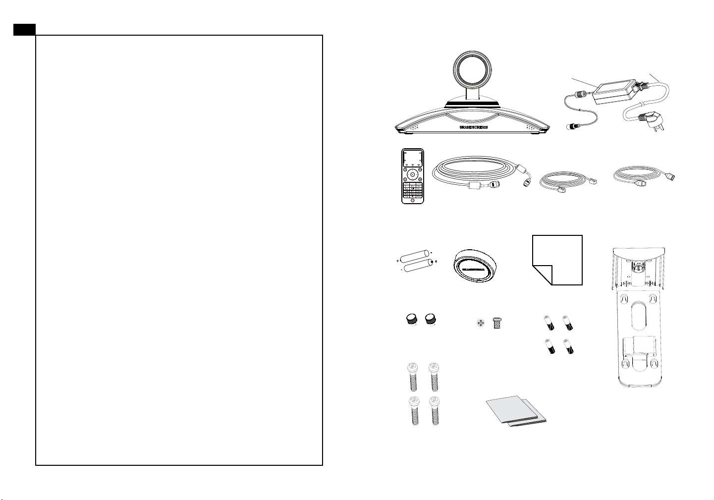
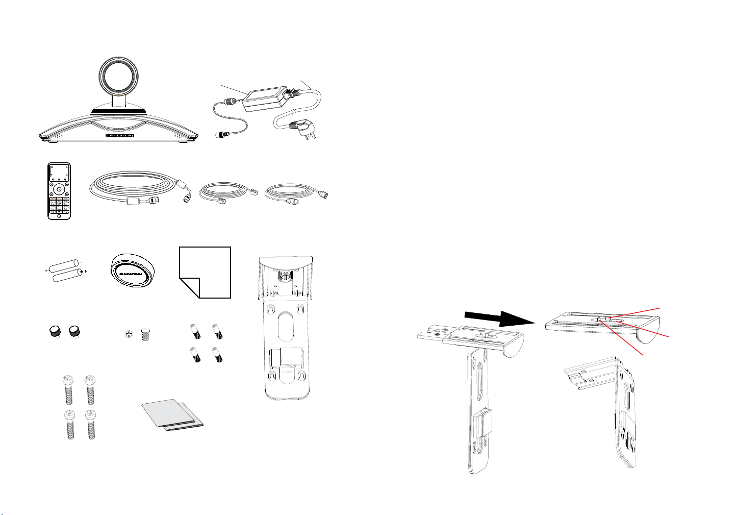
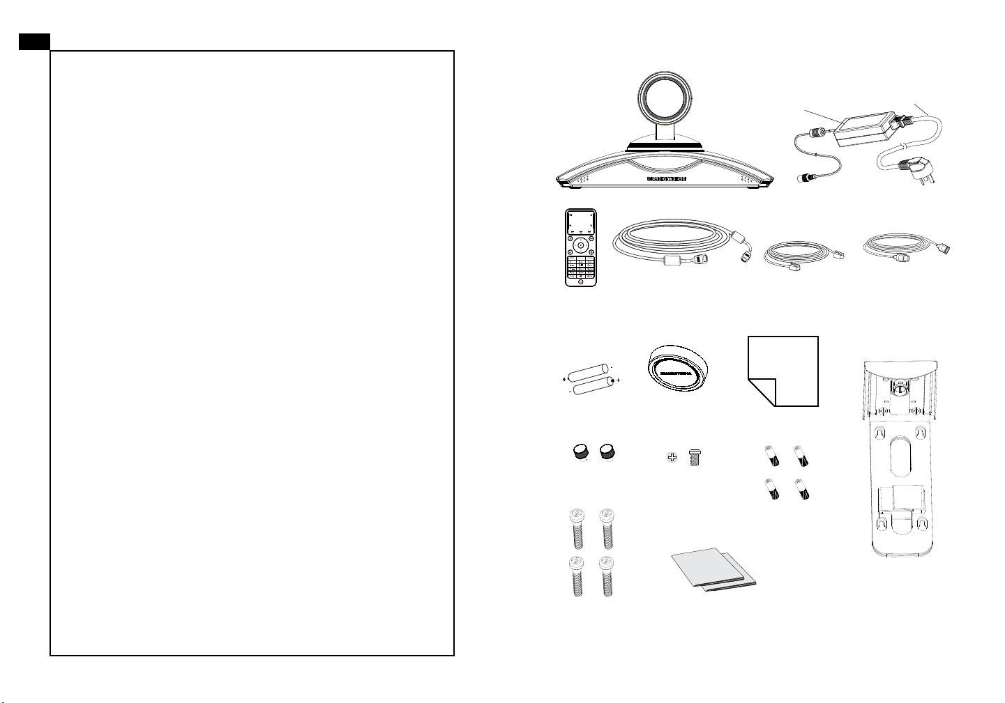
PACKAGE CONTENTS:
The GVC3200 is not pre-congured to support or
carry emergency calls to any type of hospital, law
enforcement agency, medical care unit (“Emergency
Power
adapter
Power cord
Service(s)”) or any other kind of Emergency Service.
You must make additional arrangements to access
Emergency Services. It is your responsibility to purchase SIP-compliant Internet telephone service, prop-
1 X GVC3200 Main Case
1 X 12V Power Adapter Set
erly congure the GVC3200 to use that service, and
periodically test your conguration to conrm that it
works as you expect. If you do not do so, it is your responsibility to purchase traditional wireless or landline
telephone services to access Emergency Services.
GRANDSTREAM DOES NOT PROVIDE CONNECTIONS TO EMERGENCY SERVICES VIA THE
1 X Remote
Control
+
-
1 X 1.5m HDMI Cable
2 X 3m HDMI Cable
1 X 5m HDMI Cable
-
+
1 X Ethernet Cable
(1.5m)
1 X USB
Extension Cable
(5m)
GVC3200. NEITHER GRANDSTREAM NOR ITS
OFFICERS, EMPLOYEES OR AFFILIATES MAY
BE HELD LIABLE FOR ANY CLAIM, DAMAGE, OR
2 X AAA
Batteries
1 X Lens Cover
1 X Lens Cleaning Cloth
LOSS. YOU HEREBY WAIVE ANY AND ALL SUCH
CLAIMS OR CAUSES OF ACTION ARISING FROM
OR RELATING TO YOUR INABILITY TO USE THE
GVC3200 TO CONTACT EMERGENCY SERVICES,
AND YOUR FAILURE TO MAKE ADDITIONAL AR-
2 X Screws
Type 1
2 X Screws
Type 2
4 X Bolts for
Screws Type 3
RANGEMENTS TO ACCESS EMERGENCY SERVICES IN ACCORDANCE WITH THE IMMEDIATELY
PRECEDING PARAGRAPH.
4 X Screws
Type 3
Note: 1 set of external speakerphone is included to be used with the GVC3200.
1 X Quick Installation Guide/
1 X GPL License
1 X Wall Mount Bracket
(Including Part A and Part B
attached to each other)
1 2
Page 4
PRECAUTIONS:
WARNING: Use only the power adapter included in the GVC3200 package.
Using an alternative non-qualied power adapter may possibly damage the unit.
WARNING:
up or rmware upgrade. You may corrupt rmware images and cause the unit to
malfunction.
Please DO NOT power cycle the GVC3200 during system boot
OVERVIEW:
The GVC3200 offers businesses a revolutionary video conferencing system with
unprecedented exibility and the support for multiple popular video conferencing
protocols out of the box. Based on Android 4.4™, the GVC3200 offers full access
to all video conferencing apps in the Google Play™ Store such as Skype™, Skype
for Business™, Google Hangouts™ and more, in addition to Grandstream’s industry leading SIP-based video conferencing platform. The GVC3200 sets a new
bar for enterprise class video conferencing solution in terms of exibility, interoperability, system openness, application richness and ease of use in the modern
Internet age.
INSTALLATION:
The GVC3200 can be installed in the following three ways:
Option 1: Place on desktop.
Option 2: Mount on TV/Monitor. Wall mount bracket is required.
Option 3: Mount on wall. Wall mount bracket is required.
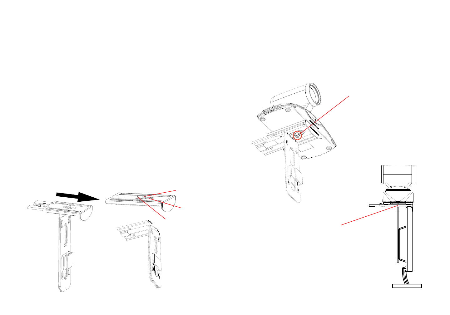
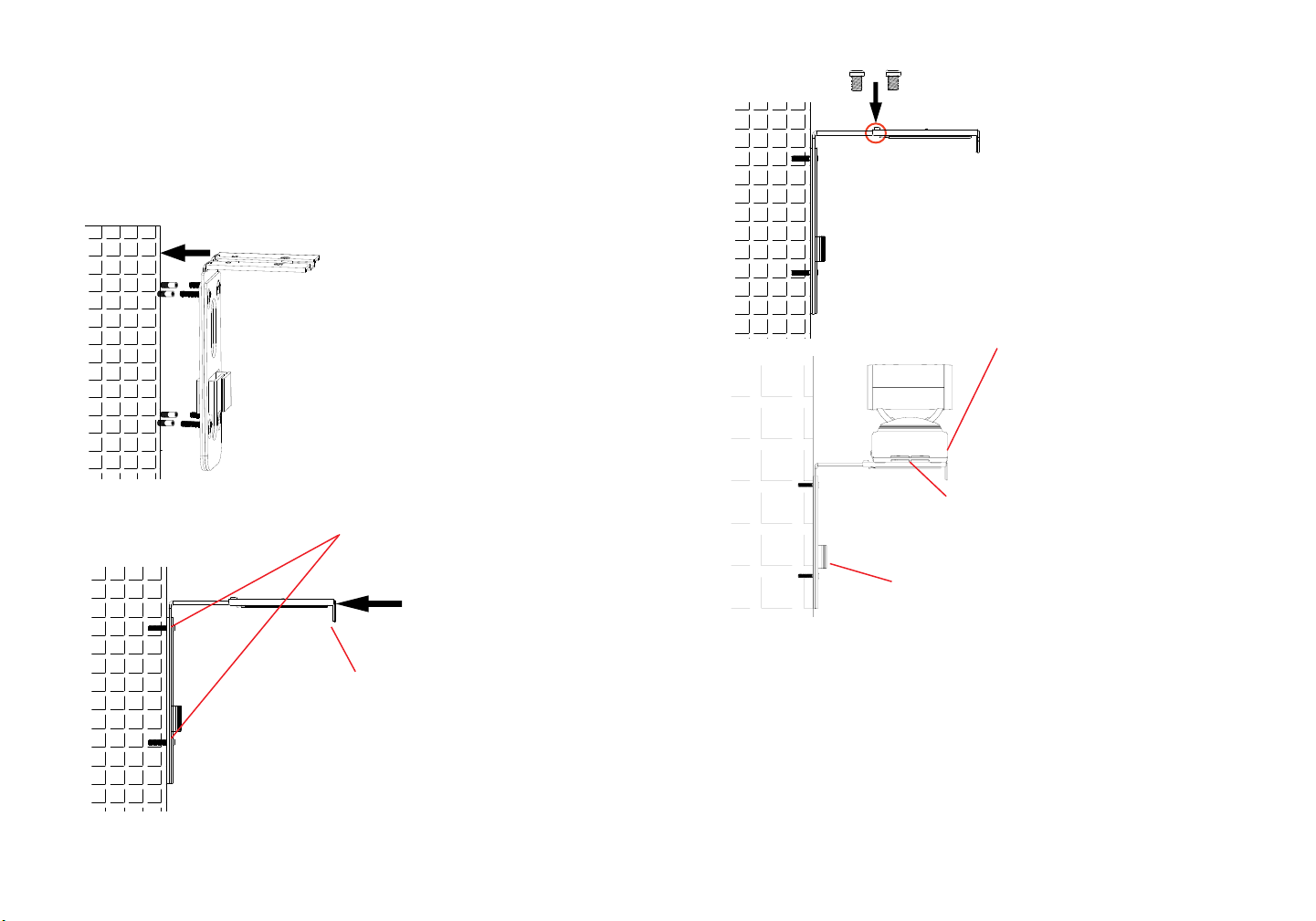
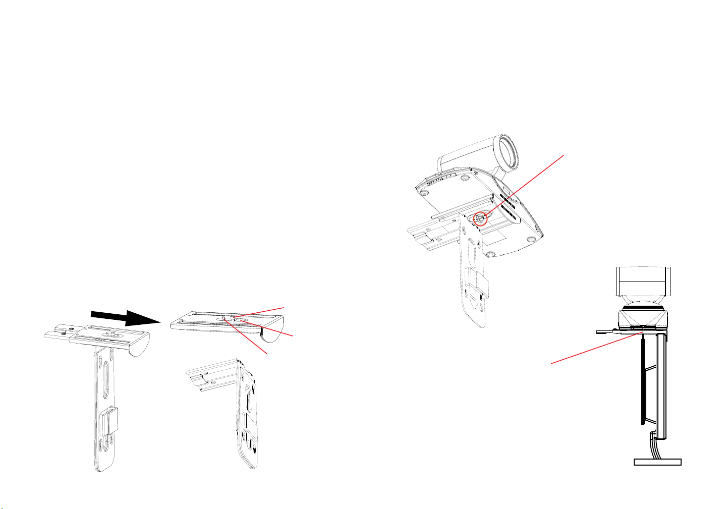
The wall mount bracket comes assembled as one piece. It can be separated into
two parts by sliding/pushing Part A outwards from Part B.
Slide or push Part A outwards.
Part A
Built-in
Screw
Silicon
Stopper
Locating Pin
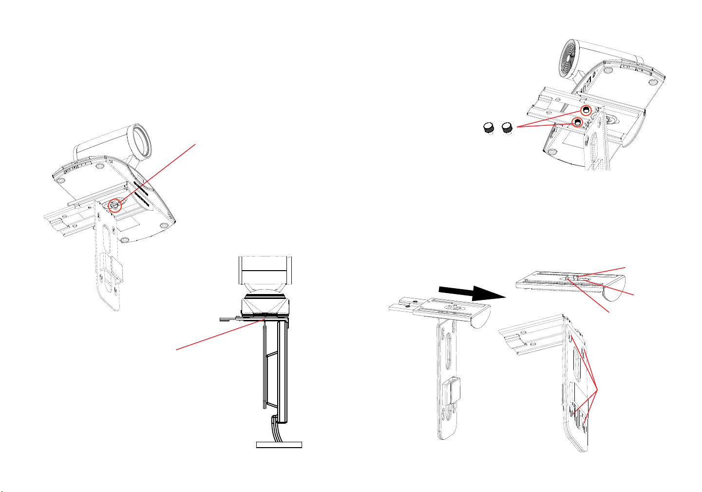
INSTALLING BRACKET TO MOUNT THE GVC3200 ON
TV/MONITOR:
1. Locate the wall mount bracket in the package and identify Part A and Part B.
Please DO NOT detach part A from part B when mounting the bracket on TV.
2. Place GVC3200 on the top of the wall mount bracket Part A. See gure below.
The locating pin on Part A should t into the hole on the bottom of the GVC3200.
3. Tighten the built-in screw on
wall mount bracket Part A to
make sure the GVC3200 ts
securely.
4. Mount the wall mount bracket on top
of the TV from behind the TV. Slide
wall mount bracket Part B on Part A
carefully to adjust the space until the
TV can be clamped in properly.
Part B
3 4
Page 5
5. Install screw Type 1 to each of the two
holes on Part B, as highlighted on the
right.
2 X Screws
Type 1
6. Manage the wire harness with the Hook-and-loop fastener on wall mount
bracket Part B.
INSTALLING BRACKET TO MOUNT THE GVC3200 ON
WALL:
1. Locate the wall mount bracket in the package and identify Part A and Part B.
Detach Part A from Part B by sliding Part A out.
Built-in
Slide Part A outwards
Part A
Screw
Silicon
Stopper
Locating Pin
2. On wall mount bracket Part B, there are four holes on it for screw Type 3. Align
Part B against the wall where you would like to place the wall mount.
3. According to the position of the four holes on Part B, locate the corresponding
spots on the wall and drill the holes.
4. Fit the four bolts into each hole on the wall. Please make sure the glossy side
is placed outwards. See gure below.
5. Mount the wall mount bracket Part B
to the wall. Then put the four screws
Type 3 into each bolt.
6. Tighten the screws so that Part B
can be securely placed against the
wall.
Part B
Four holes for wall
mount, using screw
Type 3
7. Slide the wall mount bracket Part A
into Part B, as indicated in the above
arrow.
65
Page 6

8. Align Part A and Part B at the 2
holes as highlighted below. Install
screw Type 2 to each of the hole
and tighten it.
Note: “USB” port of the GVC3200 is not for connecting speaker. Connecting
speaker to “USB” port might cause speaker work improperly.
4. Connect the 12V DC output plug to the power jack on the GVC3200; plug the
power adapter into an electrical outlet.
9. Place GVC3200 on the top of the
wall mount bracket Part A. On the
wall mount bracket Part A, the
locating pin should t into the hole
on the bottom of the GVC3200.
10. Tighten the built-in screw on wall mount
bracket Part A to make sure the GVC3200
ts securely.
11. Manage the wire harness with the Hook-and-loop
fastener on wall mount bracket Part B.
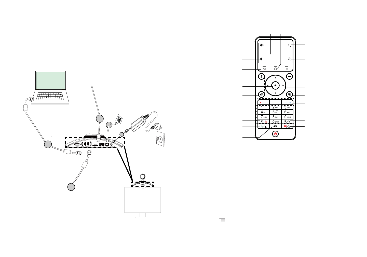
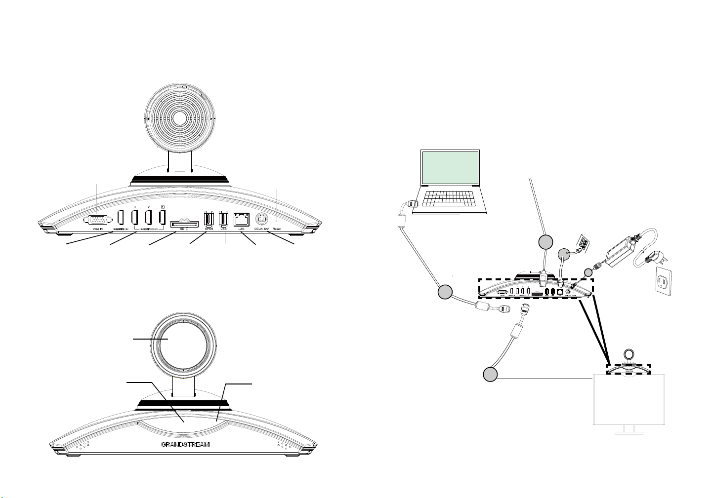
HDMI IN HDMI OUT
5. The OLED in the front of the GVC3200 will display booting up information.
Before continuing, please wait for the IP address information to show up on the
OLED. The display device (e.g., TV) will show the idle HOME screen with IP
address on the top status bar as well.
VGA IN
Port 1/2/3
Lens
SD Card
Slot
SPEAKER
Port
USB Port
RESET
DC-IN 12VLAN Port
CONNECTING THE GVC3200
1. Connect the LAN port of the GVC3200 to the RJ-45 socket of a hub/switch or
a router (LAN side of the router) using the Ethernet cable.
2. Connect the HDMI [1] port of the GVC3200 to the HDMI port of the main display
device (e.g., TV) using the HDMI cable. Connect HDMI port 2 and then HDMI
port 3 if you have additional display devices.
Note: Please make sure to follow the port order when connecting HDMI port 1, 2
and 3. The GVC3200 will not work correctly if connecting HDMI port 2 or 3
without HDMI port 1 connected.
3. Connect the USB cable of the speaker to the “SPKR” port of the GVC3200.
OLED. It shows IP
address information
after bootup. For example,
IP: 192.168.40.123
LED Indicator
7 8
Page 7
6. Insert your SD card into the SD card slot. The recording les will be saved in
SD card.
7. (Optional) Connect presentation device (e.g., a laptop) to the GVC3200 HDMI
IN port or VGA IN port for presentation purpose during conference call.
8. (Optional) Connect USB accessory (e.g., mouse, keyboard, USB ash drive and
etc) to the USB port.
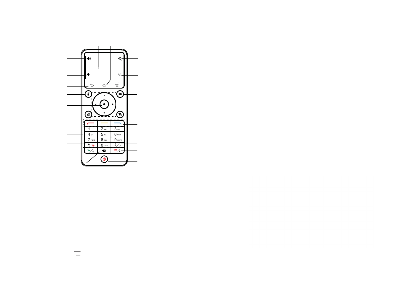
USING THE GVC3200 REMOTE CONTROL
Trackpad
Volume Up
Home
Zoom In
Connecting example:
Connect HDMI cable
from GVC3200 HDMI
IN port to laptop’s
HDMI port. This is for
presentation.
Connect the external speakerphone to GVC3200 SPKR port.
Use the USB extension cable in
the package if necessary.
Connect Ethernet cable
from GVC3200 LAN
port to hub/switch/router
(LAN side).
12V DC power
adapter is
connected into
outlet.
Volume Down
Back
Mute/DND
OK
PIP
Standard Keypad
* / Record
Send / Answer / Add
Party Into Conference
Backspace
1. Open the battery cover on the back of the remote control. Place two AAA
batteries proprely and put the cover back on.
2. When using the GVC3200 for the rst time, the remote control should be paired
and connected to it via Bluetooth already. After the GVC3200 fully boots up, tap
on the OK button on the remote control to initiate the connection. Then the
remote control can be used normally.
Zoom Out
Menu
Camera
Navigation Keys:
Up / Down / Left / Right
Presentation
Shortcut Keys:
Red / Yellow / Blue
# / Information
End Call / Remove
Party From Conference
Power ON / OFF
If the remote control is not paired with the GVC3200 anymore (e.g., a factory reset
is made), follow the steps below to pair and connect the remote control:
Connect HDMI cable from the
GVC3200 HDMI OUT port 1 to
TV’s HDMI port.
1. Connect a USB mouse to the GVC3200 USB port. Or, log in the GVC3200 web
UI and click on “Remote Control” on the upper right corner to bring up the
virtual remote control.
2. Use the USB mouse or the virtual remote control to navigate to the idle screen
Menu->Settings->Network->Bluetooth on the TV.
3. Select and click on “Search for devices”.
Note:
For more information about how to install and connect the GVC3200, please visit
4. On the remote control, press OK button and number 5 button at the same time
for about 4 seconds. This will initiate pairing process on the remote control.
the GVC3200 product web page from http://www.grandstream.com/support
9 10
Page 8
5. The remote control MAC address will show in the new device list on your TV.
Select it and it will be paired and connected to the GVC3200 shortly.
Note:
1. Users can also download GVC3200 Bluetooth remote control app for Android™
and install to your Android™ device. This app can be used as an alternative for
the remote control in the GVC3200 package.
2. For more information about how to use the GVC3200 Bluetooth remote control
for Android™, please refer to the GVC3200 user manual:
http://www.grandstream.com/support
CONFIGURING GVC3200 VIA WEB UI:
1. Ensure your GVC3200 is properly powered up and connected to the Internet.
2. The IP address of the GVC3200 will show on the OLED in the front of the
GVC3200. It will also show on the top status bar of the connected display device
(e.g., TV) via HDMI.
3. Type the IP address in your PC’s browser (see gure below).
4. The default username and password for administrator are “admin” and “admin”.
The default username and password for user are “user” and “123”.
5. In the web GUI, select Settings->Account->General Settings page to congure
Account name, SIP Server, SIP User ID, Authenticate ID and Authenticate
Password to register the account on the GVC3200.
6. The network settings can be congured under web UI->Settings->Network
Settings page; PTZ Control and Preset Settings can be accessed under web
UI->Device Control->Video Control page.
7. Please contact your ITSP (Internet Telephony Service Provider) for additional
settings that may be necessary to congure the GVC3200.
ZH
GVC3200不预设对医院,执法机构,医疗中
心(急救服务)以及各种紧急服务的紧急通话服
务。用户必须自行设定紧急通话功能。用户必
须自行购买SIP兼容的网络电话服务,正确的设
定GVC3200使用该服务,并定期测试您的配置
以确保GVC3200如预期工作,否则请购买传统
无线或有线电话服务来拨打紧急通话。
Grandstream Networks 公司的GVC3200不支
持紧急通话服务。Grandstream Networks公
司、其管理者和员工以及其相关机构对此所造
成的任何索赔、损失或者损害都不负有任何法
律追究责任。在此,您将无权对任何以及所有
由于无法通过GVC3200拨打紧急电话以及没有
遵照前段文字描述而造成紧急通话失败的事件
提出诉讼。
For the detailed user manual, please download from:
http://www.grandstream.com/support
11 12
Page 9
设备包装清单:
GVC3200话机(1台)
1.5米 HDMI线 (1根)
遥控器(1个)
+
-
3米 HDMI线 (2根)
5米 HDMI线 (1根)
-
+
电源适配器
1.5米 网线
(1根)
电源(1个)
5米 USB 延长线
(1根)
电源线
注意事项:
警告:请使用设备包装中的电源。使用其他没有经过认证的替代电源适配器有可
能对设备造成损害。
警告:请不要在设备启动未完成的时候或设备的软件升级过程中断开电源。如
上所述的操作会导致设备本身的程序损坏,进而造成设备无法启动。
产品概览:
GVC3200支持多种流行的视频会议协议以及平台。其灵活性为现代企业提供了
一种突破性的视频会议解决方案。GVC3200基于安卓4.4系统,除了能够完美兼
容潮流公司领先于业界先进水平的基于SIP方案的视频会议系统外,还能够完整
对接谷歌应用商店上的视频会议应用,如 Skype™, Skype for Business™, Google
Hangouts™等。GVC3200使用一种新型的正在申请专利的MCU技术,能够支持多
达9方SIP协议和其他协议之间的本地混合的会议。同时,GVC3200兼容一些第三
方视频会议解决方案。GVC3200的灵活性、互用性、开放性以及应用的丰富性、
贴合现代的易用性使其能够成为企业级视频会议解决方案的一座新里程碑。
安装设备:
GVC3200支持三种安装方式:
方式1:置于桌面
方式2:使用墙体安装支架,安装在电视等显示设备上
方式3:使用墙体安装支架,安装在墙上
墙体安装支架由两部分组成,通过滑动和推拉可以拆分支架A和支架B。
AAA电池
(2节)
螺丝类型1
(2个)
螺丝类型3(4个)
注意:GVC3200配有一套外接扬声器,可与GVC3200连接使用。
镜头盖
(1个)
螺丝类型2
(2个)
快速安装手册(1本)/
GPL许可证 (1本)
擦镜布(1块)
螺栓 - 用于螺丝类型3
(4个)
(1套,由支架A和支架B
墙体安装支架
组成,两部分可拆分)
滑动或者推拉支架A
支架A
固定螺丝
胶塞
定位针
支架B
13 14
Page 10
安装设备在电视或显示器上:
1. 安装需要使用到GVC3200包装中的墙体支架。请保持支架A和支架B连接,先不
要将支架拆分。
2. 将GVC3200置于支架A上。见下图。支架A上的定位针要能够插入GVC3200底
部的定位孔中。
5. 将螺丝类型1分别安装到支架B
的两个孔中,如右图所示。
4. GVC3200与墙体安装支架固定
后,将墙体安装支架从显示设备
后部放置于显示设备顶上。小心
滑动支架A和支架B,调整两者之
间的距离,确保显示设备适当卡
入支架A和支架B之间。
3. 拧紧固定螺丝,确保GVC3200
可以稳定置于支架A上。
螺丝类型1(两个)
6. 使用支架B上的魔术贴整理和固定需要用的线缆。
安装设备在墙上:
1. 安装需要使用到GVC3200包装中的墙体支架。请滑动或者推拉支架A,将其与
支架B分离。
固定螺丝
滑动或者推拉支架A
支架A
支架B上有四个螺
丝孔,用于螺丝类
型3,固定到墙上
胶塞
定位针
支架B
15 16
Page 11
2. 在支架B上,有四个螺丝孔,用于螺丝类型3。将支架B靠在墙上并且移到需要
安装的位置。
3. 根据支架B的四个螺丝孔在墙上的位置,打出四个孔,用于装入螺栓。
4. 将四个螺栓安装到步骤3中打的四个孔里。请确保螺栓光滑的一端朝墙外。
5. 将支架B放置到墙上,然后把螺
丝类型3从支架B上的四个孔穿入
到四个螺栓中,固定支架B。
6. 拧紧四颗螺丝,确保支架B稳定
靠在墙上。
8. 将支架A和支架B在左图所示的
螺孔处对准。然后使用螺丝类
型2从上往下装入螺孔并拧紧。
9. 将GVC3200置于支架A上。支架A上
的定位针要能够插入GVC3200底部
的定位孔中。
10. 拧紧固定螺丝,确保GVC3200
可以稳定置于支架A上。
11. 使用支架B上的魔术贴整理和固定需要用的线缆。
连接GVC3200:
7. 将支架A滑入支架B,如以上箭头
所示。
1. 用网线将设备的网络接口和外部网络接口(如:集线器或交换机上的RJ-45网
络接口)连接。
2. 使用HDMI线将主显示设备连接到GVC3200的HDMI输出口1。如果有更多显示
设备,请分别依次连接到HDMI输出口2和3。
注意:连接显示设备时,请确保按照HDMI输出口1,2,3的顺序依次连接。如
果在未连接HDMI输出口1的情形下就连接2或者3,设备将无法正常工作。
3. 使用USB线将外接扬声器连接到GVC3200的SPKR口。
17 18
Page 12
注意:请不要将外接扬声器连接到GVC3200上的USB接口。连接后,外接扬声器
可能不会正常工作。
4. 用12V电源适配器连接电话电源接口和交流电源插座。
VGA输入
重置
6. 将SD卡插入GVC3200的SD卡插槽。录音文件将保存到SD卡中。
7. (可选)使用HDMI线或者VGA线将演示设备(比如,笔记本电脑)连接到
GVC3200的HDMI输入接口或者VGA输入接口。
8. (可选)将USB辅助设备,例如鼠标、键盘或者USB存储设备接入GVC3200的
USB接口。
连接示例:
使用USB线将外接扬声器连接到
GVC3200的SPKR口。如有需要,可
使用GVC3200包装中的USB延长线
用网线连接GVC3200网络接口
和外部网络接口,如:集线器
或交换机上的RJ-45网络接口
HDMI输入
5. GVC3200的OLED会显示启动信息。继续操作之前,请耐心等待IP地址显示在
OLED上。与GVC3200连接的显示设备将会显示GVC3200主界面,IP地址会
显示在顶部的状态栏。
OLED。设备启动后,IP
地址显示在OLED上,例
如:192.168.40.123
HDMI输出1/2/3
镜头
SD卡插槽 扬声器接口
USB接口
网络接口 电源接口
LED指示灯
使用HDMI线连
接笔记本电脑
和GVC3200的
HDMI输入接
口,用于演示
使用HDMI线高清电视连接到
GVC3200的HDMI输出口1
注意:请登录以下网址获取更多连接和安装GVC3200的信息:
http://www.grandstream.com/support
将12V DC电源
连接到插座
19 20
Page 13
使用GVC3200遥控器:
5. 遥控器的MAC地址会显示在显示设备蓝牙界面列表。选择该设备将会与
GVC3200配对和连接。
触控板
音量增加
音量减小
返回
静音/免打扰
确认
布局
标准数字键盘
*/录音
回删
1. 打开遥控器后盖,安装两节AAA电池,将后盖装回。
2. 第一次使用GVC3200时,遥控器与GVC3200已经配对。GVC3200启动后,按
下遥控器上的确认键,遥控器与GVC3200连接成功后,可正常使用。
首页
变焦:放大
变焦:缩小
菜单
摄像头控制
导航键
演示
复用键
#/详情
挂机/删减成员发送/接听/添加成员
关机
注意:
1. 用户可以下载蓝牙遥控器应用,安装在安卓设备上。该应用可以作为遥控器的
替代。
2. 请登录以下网址获取GVC3200用户手册和使用蓝牙遥控器应用的信息:
http://www.grandstream.com/support
通过Web界面配置GVC3200:
1. 确保GVC3200正常启动并且连接网络。
2. GVC3200获取到的IP地址将会显示在OLED上。IP地址也会显示在显示设备顶
部的状态栏。
3. 在电脑浏览器输入话机的IP地址(电话和电脑必须在同一个网段),见下图。
4. 默认管理员的用户名是“admin”,密码是“admin”;默认终端用户的用户名
是“user”,密码是“123”。
5. 在Web界面,选择设置->账号->通用设置页面,配置用户名、SIP服务器、SIP用
户ID、 认证ID、认证密码等信息注册账号。
6. 若需设置网络配置,进入设置->网络页面;若需配置PTZ和预制位,进入设备控
制->摄像头控制页面。
7. 如有其它需要的设置,请联系您的服务提供商。
如果遥控器与GVC3200未配对(如,GVC3200重置后会取消与遥控器配对),
请按照以下步骤配对连接:
1. 连接USB鼠标至GVC3200的USB接口。或者登陆GVC3200的Web界面,按下页
面右上角的“遥控器”字样,打开Web界面上的虚拟遥控器。
2. 使用鼠标或者虚拟遥控器,导航至GVC3200显示设备主界面上->设置->网络->
蓝牙。
3. 点击右上角的菜单图标 ,选择搜索新设备。
4. 搜索开始后,同时按下遥控器上的确认和数字5键大概4秒,触发遥控器配对。
请登录以下网址获取GVC3200用户手册:
http://www.grandstream.com/support
21 22
Page 14
ES
El GVC3200 no viene pre congurado ni tiene acceso a
información de ningún tipo de servicio de llamadas de
emergencia, hospitales, servicios policiales, unidades de
cuidados médicos o cualquier otro tipo de servicio de socorro. Usted deberá hacer las coordinaciones necesarias
para poder acceder a estos servicios. Será su responsabilidad, el contratar el servicio de telefonía por internet com-
patible con el protocolo SIP, congurar apropiadamente el
GVC3200 para usar dicho servicio y periódicamente probar
su conguración para conrmar su funcionamiento de acuerdo a sus expectativas. Si usted decide no hacerlo, será
su responsabilidad comprar servicios de telefonía tradicio-
nal, ya sea por línea ja o inalámbrica para poder acceder
a los servicios de emergencia.
GRANDSTREAM NO PROVEE CONEXIONES CON
NINGUN SERVICIO DE EMERGENCIA MEDIANTE EL
GVC3200. NI GRANDSTREAM NI SUS DIRECTORES,
EMPLEADOS O AFILIADOS, PUEDEN SER SUJETOS
REPONSABLES POR NINGUN RECLAMO, DAÑO O
PERDIDA. POR LO TANTO, USTED RENUNCIA A SU
DERECHO DE RECLAMO O DENUNCIA QUE PUEDA
SURGIR DEBIDO A LAS LIMITACIONES EN EL USO
DEL GVC3200 PARA CONTACTAR A LOS SERVICIOS
DE EMERGENCIA, ASI COMO A SU NEGLIGENCIA DE
REALIZAR LAS COORDINACIONES NECESARIAS PARA
ACCEDER A TODOS LOS SERVICIOS DE EMERGENCIA, MENCIONADOS EN EL PARRAFO PRECEDENTE.
CONTENIDO DEL PAQUETE:
Cable de
Adaptador de
Poder
1 X GVC3200
1 X Control
Remoto
+
-
2 X AAA Pilas
2 X Tornillos
Tipo 1
4 X Tornillos
Tipo 3
Nota: Se incluye 1 teléfono altavoz externo para ser usado con el GVC3200.
1 X Cable HDMI (1.5m)
2 X Cable HDMI (3m)
1 X Cable HDMI (5m)
-
+
1 X Tapa de
la Lente
2 X Tornillos
Tipo 2
1 X Guia de Instalación Rápida
1 X Licencia GPL
1 X Paño de limpieza para
1 X Cable de Red
4 X Pernos para
tornillos Tipo 3
1 X 12V Fuente de Poder
(1.5m)
lentes
1 X Soporte de montura de Pared
(Incluye Parte A y Parte B
Alimentación
1 X Cable de
Extensión USB
(5m)
unidos entre si)
23 24
Page 15
PRECAUCIONES:
CUIDADO: Use solamente el adaptador de corriente incluido con el GVC3200.
Usar uno alternativo puede dañar el equipo.
CUIDADO:
la actualización del rmware. La interrupción de la actualización del rmware
puede causar mal funcionamiento del equipo.
Por favor NO apague el GVC3200 durante el arranque o durante
INFORMACIÓN GENERAL:
El GVC3200 ofrece a las empresas un sistema de videoconferencia revolucio-
nario con una exibilidad sin precedentes y soporte para multiples protocolos
de videoconferencias populares. Basado en Android 4.4™, el GVC3200 ofrece
total acceso a todas las aplicaciones de videoconferencia disponibles en Google
Play™ Store tales como Skype™, Skype for Business™, Google Hangouts™,
entre otros - además de la plataforma de la industria Grandstream líder en vid-
eoconferencias basadas en SIP. El GVC3200 ja una nueva solución para videoconferencias de clase empresarial en términos de exibilidad, interoperabilidad,
apertura de sistemas, rico en aplicaciones y facilidad de uso en la edad moderna
del internet.
INSTALACIÓN:
El GVC3200 puede ser instalado de las siguientes tres maneras:
Opción 1: Situado en el escritorio.
Opción 2: Montura sobre el TV/Monitor. Se requiere de una montura de pared.
Opción 3: Montura en la pared. Se requiere de una montura de pared.
La montura de pared viene ensamblada como una sola pieza. Puede ser separada en dos partes al deslizar o empujar hacia afuera la Parte A de la Parte B.
Deslice o presione la Parte A hacia el exterior
Parte A
Soporte
para tornillo
Tapón de
Silicona
Pasador de
posicionamiento
INSTALANDO EL SOPORTE PARA MONTAR EL GVC3200
SOBRE TV/MONITOR:
1. Localice la montura de pared en el paquete e identique la Parte A y la Parte B.
Por favor NO despegue la Parte A de la B al montar el soporte sobre la TV.
2. Situe el GVC3200 en la parte superior de la montura de pared de la Parte A.
Ver gura. El pasador de posicionamiento sobre la Parte A debería encajar en
el agujero de la parte inferior del GVC3200.
3. Apriete el soporte de tornillo
en la montura de pared de la
Parte A para asegurarse de
que el GVC3200 se ajuste de
manera segura.
4. Monte el soporte de pared en la
parte superior del TV por detrás
de éste. Deslice cuidadosamente
la montura de pared de la Parte
B sobre la Parte A para ajustar el
espacio hasta que el TV se sujete
correctamente.
Parte B
25 26
Page 16

5. Instale el tornillo Tipo 1 a cada uno de
los dos agujeros en la Parte B como se
destaca a la derecha.
2 X Tornillos
Tipo 1
6. Administre los cables con el sujetador de gancho en la montura de pared de
la Parte B.
INSTALANDO EL SOPORTE PARA MONTAR EL
GVC3200 EN LA PARED:
1. Localice la montura de pared en el paquete e identique la Parte A y la Parte B
al deslizar la Parte A hacia afuera.
Deslice la Parte A hacia el exterior
Parte A
Soporte
para
tornillo
Tapón de
Silicona
Pasador de
posicionamiento
2. Sobre la montura de pared de la Parte B, hay cuatro agujeros para tornillos Tipo
3. Alinie la Parte B contra la pared donde le gustaría jar la montura de pared.
3. De acuerdo a la posición de los cuatro agujeros de la Parte B, localÍcelos en la
pared correspondiente y taladre los agujeros.
4. Fije los cuatro pernos en cada agujero de la pared. Por favor asegúrese de que
el lado lustroso esté situado hacia el exterior. Ver gura abajo.
5. Monte el sujetador de pared de la
Parte B. Luego inserte los cuatro
tornillos Tipo 3 en cada perno.
6. Apriete los tornillos de manera que
la Parte B pueda ser jada de
manera segura contra la pared.
Parte B
Para los agujeros
de la montura de
pared use los tornillos Tipo 3
7. Deslice la montura de pared de la
Parte A en la Parte B como se indica
en la echa de arriba.
2827
Page 17

8. Alinie la Parte A y la Parte B en los
agujeros como se destaca abajo.
Instale los tornillos Tipo 2 a cada
agujero y apriételos.
9. Situe el GVC3200 por encima del
sujetador de montura de pared
de la Parte A. Sobre el sujetador de
la Parte A, el pasador de posiciona
miento debería encajar en el
agujero inferior del GVC3200.
Nota: El puerto “USB” del GVC3200 no es para conectar el altavoz. Conectar
el altavoz al puerto “USB” podría causar que el altavoz funcione de
manera inapropiada.
4. Conecte el plug de salida de 12V DC al enchufe de poder del GVC3200,
conecte el adaptador de poder a un toma corriente.
Entrada VGA
RESET
10. Apriete el soporte de tornillo en el sujetador
de montura de pared de la Parte A y
asegúrese de que el GVC3200 encaje de
manera segura.
11. Administre los cables con el sujetador de gancho
en la montura de pared de la Parte B.
CONECTANDO EL GVC3200:
1. Conecte el puerto LAN del GVC3200 a un puerto RJ45 de un Hub/Switch o
Router (del lado LAN del router) usando el cable Ethernet.
2. Conecte el puerto HDMI del GVC3200 al puerto HDMI del dispositivo de
visualización principal (Ejemplo un Televisor) usando el cable HDMI. Si posee
dispositivos adicionales conecte el puerto HDMI 2 y luego puerto HDMI 3.
Nota: Por favor asegúrese de seguir el orden de puertos HDMI 1,2 y 3 cuando
se conecte a éste. El GVC3200 no trabará de manera correcta si conecta
los puertos HDMI 2 o 3 sin usar el puerto HDMI 1.
3. Conecte el cable USB del altavoz al puerto “SPKR” del GVC3200.
Entrada
HDMI
5. El OLED en el frontal del GVC3200 mostrará la información de arranque. Antes
de continuar, por favor espere la información de la dirección IP a ser mostrada
en el OLED. El dispositivo de visualización (Televisor) mostrará la pantalla de
Inicio con la dirección IP en la barra superior de Estado.
Salida HDMI
Puerto 1/2/3
Lente
OLED. Muestra la
información de la
dirección IP después
de arrancar.
Por ejemplo,
IP: 192.168.40.123
Ranura de
tarjeta SD
Puerto de
Altavoz
Puerto
USB
Puerto
LAN
LED Indicator
Entrada
DC-12V
29 30
Page 18

6. Inserte su tarjeta SD dentro de la ranura para tarjetas SD. Los archivos
grabados se guardarán en la tarjeta SD.
7. (Opcional) Conecte un dispositivo de presentación (Ejemplo, una laptop) Al
puerto de entrada HDMI o al puerto de entrada VGA para propósitos de
presentación durante la llamada de conferencia.
8. (Opcional) Conecte un accesorio USB (Ejemplo, ratón, teclado, memoria USB,
entre otros) al puerto USB.
USANDO EL CONTROL REMOTO DEL GVC3200:
Trackpad
SUBIR VOLUMEN
Inicio
Acercar
Ejemplo de conexión:
Conecte el cable HDMI
del puerto de entrada
del GVC3200 al puerto
HDMI de la laptop.
Esto es para presentaciones.
Conecte el teléfono altavoz externo al
puerto SPKR del GVC3200. Use el cable
de extensión USB dentro del paquete si es
necesario.
Conecte el cable de Ethernet desde el puerto LAN del
GVC3200 a un puerto Hub/
Switch/ Router (de lado LAN).
El adaptador de
poder de 12V
DC debe estar
conectado a un
toma corriente.
BAJAR VOLUMEN
Atrás
Muto/DND
OK
PIP
Teclado Estándar
* / Grabar
Enviar/Responder/
Agregar grupo a la
conferencia
Tecla de retroceso
1. Abrir la cobertura de la batería en la parte posterios del control remoto. Colocar
dos baterías AAA adecuadamente y poner la cobertura nuevamente.
2. Cuando use el GVC3200 por primera vez, el control remoto ya debería estar
emparejado y conectado via Bluetooth. Luego de que el GVC3200 arranque
totalmente, marque sobre el botón de OK en el control remoto para iniciar la
conexión. En ese momento el control remoto puede ser usado.
Si el control remoto ya no está emparejado con el GVC3200 (Ejemplo, se hace
Alejar
Menú
Camara
Teclas de Navegación:
Arriba/Abajo/
Izquierda/Derecha
Presentación
Teclas de acceso
directo:
Rojo/Amarillo/Azúl
# / Información
Terminar llamada/
Remover grupo de la
conferencia
Encendido/Apagado
un reinicio de fábrica), siga los pasos a continuación para emparejar y conectar
el control remoto:
Conecte el cable HDMI del
puerto 1 de salida del GVC3200
al puerto HDMI del Televisor.
1. Conecte un ratón USB al puerto USB del GVC3200. O ingrese en la web GUI
del GVC3200 y clic sobre “Control Remoto” en la parte superior de la esquina
derechapara que aparezca el control remoto virtual.
2. Use el ratón USB o el control remoto virtual para navegar en la pantalla Menú
Nota:
Para mayor información acerca de cómo instalar y conectar el GVC3200, por
favor visite la página web del producto GVC3200 desde
http://www.grandstream.com/support
-> Opciones -> Red -> Bluetooth en el Tv.
3. Seleccione Menú y clic sobre “Búsqueda de dispositivos”.
4. En el control remoto, presione el botón OK y el número 5 al mismo tiempo por
aproximadamente 4 segundos. Esto iniciará el proceso de emparejamiento en
el control remoto.
31 32
Page 19

5. La dirección MAC del control remoto se mostrorá en la lista de nuevos dis
positivos en el televisor. Seleciónelo y estará en breve emparejado y conectado
al GVC3200.
Nota:
1. Los usuarios pueden descargar aplicaciones Android™ de control remoto via
Bluetooth al GVC3200 e instalarlas a su dispositivo android. Estas aplicaciones
pueden ser usadas como una alternativa para control remoto dentro del pa-
quete del GVC3200.
2. Para mayor información acerca de cómo usar el control remoto Bluetooth del
GVC3200 para Android™, por favor remítase al manual de usuario de el
GVC3200: http://www.grandstream.com/support
Congurando el GVC3200 utilizando un navegador
Web:
1. Asegúrese de que su GVC3200 esté prendido y conectado a internet de
manera apropiada.
2. La dirección IP del GVC3200 se mostrará sobre el OLED en el frontal del
GVC3200. Esta se mostrará en la barra superior de estado del dispositivo de
visualización (Ejemplo, Televisor) via HDMI.
3. Tipee la dirección Ip en el navegador de su PC (ver gura).
4. El nombre de usuario y contraseña por defecto para el administrador es “admin”
y “admin”, y el nombre de usuario y contraseña por defecto para el usuario es
“user” y “123”.
5. En la web GUI, seleccione Opciones -> Cuenta -> Opciones Generales para
congurar el nombre de la cuenta, servidor SIP, ID de usuario SIP, ID de auten-
ticación y contraseña de autenticación para registrar la cuenta en el GVC3200.
6. La opción de Red puede ser congurada bajo la Web GUI -> Opciones ->
Opciones de Red, Control PTZ y Ajustes Predenidos pueden ser accedidos
bajo la Web GUI -> Control de dispositivo -> Video.
7. Por favor contacte su ITSP (Proveedor de servicios de telefonía de internet)
para ajustes adicionales que puedan ser necesarios en la conguración del
GVC3200.
FR
Le GVC3200 n’est pas préconguré pour prendre en
charge ou de procéder les appels d’urgence à tout type
d’hôpital, d’application de la loi, ou unité de soins médicaux (“Service (s) d’urgence”) ou tout autre type de service d’urgence. Vous devez faire des arrangements pour
l’accès aux services d’urgence. C’est votre responsabilité d’acheter un service téléphonique Internet compatible
SIP, congurer correctement le GVC3200 à utiliser ce service et, périodiquement, de tester votre conguration an
de conrmer qu’il fonctionne comme prévu. Si vous ne le
faites pas, c’est votre responsabilité d’acheter un accès
au service téléphonique traditionnel sans l ou laire an
d’accéder aux services d’urgence.
GRANDSTREAM NE FOURNIT AUCUNE CONNEXION AUX SERVICES D’URGENCE VIA LE GVC3200. NI
GRANDSTREAM, NI SES DIRIGEANTS, EMPLOYES
OU FILIALES PEUVENT ETRE TENUS RESPONSABLE
POUR TOUTE RECLAMATION OU CAUSE D’ACTION
DECOULANTE OU RELATIVE A VOTRE INCAPACITE
D’UTILISER LE GVC3200 POUR CONTACTER LES
SERVICES D’URGENCE ET VOTRE ECHEC DE FAIRE
DES ARRANGEMENTS SUPPLEMENTAIRES POUR ACCEDER AUX SERVICES D’URGENCE EN CONFORMITE
AVEC LE PARAGRAPHE PRECEDENT.
Para obtener el manual de usuario, favor haga click aquí:
http://www.grandstream.com/support
33 34
Page 20

CONTENU DU PACK:
1 X GVC3200 Boîtier Principal
1 X Câble HDMI (1.5m)
2 X Câble HDMI (3m)
1 X Câble HDMI (5m)
1 X Télécommande
-
+
-
2 X AAA
Piles
2 X Vis Type 1
+
1 X Couvercle
de la Lentille
2 X Vis Type 2
Adaptateur
d’alimentation
1 X Adaptateur d’alimentation 12V
1 X Câble Ethernet
(1.5m)
1 X Chiffon de Nettoyage
pour Lentilles
4 X Boulons
pour Vis Type 3
Cordon
d’alimentation
1 X Câble
d’extension USB
(5m)
PRECAUTIONS:
Avertissement: Utilisez seulement le boitier d’alimentation inclus dans le pack
du GVC3200. L’utilisation d’un boitier d’alimentation alternatif non qualié peut
endommager l’équipement.
Avertissement: Veuillez ne pas éteindre le GVC3200 pendant le démarrage du
système ou la mise à jour du rmware. Cela risque de rompre l’image du rmware
et en conséquence rendre l’unité inutilisable.
PRESENTATION:
Le GVC3200 offre pour les entreprises un système de visiocoférence révolution-
naire doté d’une exibilité sans précédent, et un support inné pour de multiple
protocoles populaires utilisés en visioconférence. Basé sur Android 4.4™, le
GVC3200 offre un accès complet aux applications de visioconférence présent
sur Google Play™ Store - comme Skype™, Skype for Business™, Google Hangouts™ et autres - en plus de la plateforme de Grandstream pionière en industrie
visioconférence basée sur SIP. Le GVC3200 établit une nouvelle barre pour les
solutions de visioconférence d’entreprises en terme de exibilité, interopérabilité,
ouverture du système, richesse d’applications et facilité d’utilisation dans l’ère
moderne d’internet.
INSTALLATION:
Le GVC3200 peut être installé selon les trois dipostitions suivantes:
Option 1: Placé sur le bureau.
Option 2: Fixation sur TV/Moniteur.
Option 3: Fixation murale. Support mural requis.
Le support mural vient assemblé en une seule partie. Ce dernier peut être séparé
en deux parties en glissant/poussant la Partie A vers l’extérieur de la Partie B.
Glisser ou pousser la Partie A vers l’extérieur
Partie A
Vis
intégré
Bouchon
en silicium
Broche de
positionnement
1 X Support de xation murale
(inclus Partie A et Partie B at-
tachés entre elles)
4 X Vis Type 3
1 X Guide d’installation rapide/
1 X License GPL
Partie B
Note: 1 haut-parleur externe est inclus pour être utiliser avec le GVC3200.
35 36
Page 21

INSTALLATION DU SUPPORT POUR FIXER LE
GVC3200 SUR TV/MONITEUR:
1. Localiser le support de xation murale dans le boitier et identier la Partie A et
la Partie B. Prière de NE PAS détacher la Partie A de la Partie B quand vous
faites le montage du support sur la TV.
2. Placer le GVC3200 en dessus du support de xation murale Partie A. Voir
gure ci-dessous. La broche de positionnement sur la Partie A doit être adaptée
au trou dans le dessous du GVC3200.
5. Installer le vis Type 1 sur chacun
des deux trous sur la Partie B, comme
vous pouvez le voir à droite.
4. Monter le support de xation murale
en dessus de la TV depuis l’arrière de
la TV. Glisser le support de xation
murale partie B sur la Partie A
soigneusement pour ajuster l’espace
jusqu’à ce que la TV peut être
propremement serré.
3. Serrer le vis intégré sur le support
de xation murale Partie A pour
être sûr que le GVC3200 est
correctement mis en place.
2 X Vis
Type 1
6. Gérer le faisceau de câblage avec la xation crochet et boucle sur support
mural Partie B.
INSTALLATION DU SUPPORT POUR FIXER LE
GVC3200 SUR LE MUR:
1. Localiser le support de xation murale dans le boitier et identier la Partie A et la
Partie B. Détacher la Partie A de la Partie B en glissant la Partie A vers l’extérieur.
Vis
Glisser la Partie A vers l’extérieur
Partie A
Quatres trous
pour xation
murale, en
utilisant les
vis Type 3
intégré
Bouchon
en silicium
Broche de
positionnement
Partie B
37 38
Page 22

2. Dans le support de xation murale Partie B, il y a quatre trous pour vis Type 3.
Aligner la Partie B contre le mur où vous voulez placer le support de xation
murale.
3. Selon la position des quatre trous sur la partie B , localiser les points
correspondants sur le mur et percer les trous.
4. Monter les quatre boulons dans chaque trou sur le mur . Prière de s’assurer que
la face brillante est placé vers l’extérieur. Voir gure ci-dessous .
8. Aligner la Partie A et la Partie B
avec les deux trous comme
indiqué en bas. Installer les vis
Type 2 sur chaque trou et serrer
le vis.
5. Monter le support de xation murale
Partie B. Ensuite placer les quatres vis
Type 3 dans chaque boulon.
6. Serrer les vis de telle sorte que la
Partie B peut être placé sur le mur
en toute sécurité.
11. Gérer le faisceau de câblage avec la xation
crochet et boucle sur support mural Partie B.
9. Placer le GVC3200 en dessus du
support de xation murale Partie A,
la broche de positionnement sur la
Partie A doit être adapté au trou
dans le dessous du GVC3200.
10. Serrer le vis intégré sur le support de
xation murale Partie A pour être sûr
que le GVC3200 est correctement mis en
place.
CONNECTER LE GVC3200:
1. Connecter le port LAN du GVC3200 au port RJ-45 d’un hub/switch ou un
7. Glisser le support de xation murale
Partie A dans la Partie B, comme
indiqué par la èche ci-dessous.
routeur (Partie LAN du routeur) en utilisant un câble Ethernet.
2. Connecter le port HDMI [1] du GVC3200 au port HDMI du dispositif d’afchage
principale (exemple: TV) en utilisant un câble HDMI. Connecter les ports HDMI
2 puis HDMI 3 si vous avez des dispositifs d’afchage addtionnels.
Remarque: Prière de suivre l’ordre des ports en connectant port HDMI 1, 2 et 3.
Le GVC3200 ne fonctionnera pas correctement si vous connectez le port HDMI 2
ou 3 sans que le port HDMI 1 soit connecté.
3. Connecter le cable USB du haut-parleur au port “SPKR” du GVC3200.
39 40
Page 23

Remarque: Port “USB” du GVC3200 n’est pas fait pour connecter le haut-parleur.
Connecter le haut-parleur au port “USB” peut causer un dysfonctionnement.
4. Connecter le port de sortie 12V DC à la prise d’alimentation sur le GVC3200;
brancher l’adaptateur d’alimentation dans une prise électrique.
6. Insérez votre carte SD dans la fente de la carte SD . Les chiers d’enregistrement
seront enregistrées dans la carte SD.
7. (Facultatif) Connecter un dispositif de présentation (par exemple, un ordinateur
portable ) au GVC3200 port HDMI IN ou port VGA IN pour des ns de
présentation lors de la conférence.
8. (Facultatif) Connecter un accessoire USB (par exemple, souris, clavier,
lecteur de ash USB et etc) au port USB.
Exemple de connection:
Connecter le haut-parelur
externe au port SPKR du
GVC3200. Utiliser le câble
d’extension USB si nécessaire.
VGA IN
HDMI IN HDMI OUT
Port 1/2/3
Port
Carte SD
Port
SPEAKER
Port USB
RESET
DC IN 12VPort LAN
Connecter le câble Ethernet
depuis le port LAN du GVC3200
à un hub/switch/routeur (partie
LAN).
5. L’OLED à la partie frontale du GVC3200 va afcher les informations de
démarrage. Avant de continuer, prière d’attendre l’afchage de l’information à
propos de l’addresse IP sur l’OLED. Le dispositif d’afchage (exemple: TV) va
afcher l’écran HOME avec l’addresse IP en haut au niveau de la barre de statut
également.
Objectif
OLED. Afche l’adresse
IP après le démar
rage. Par exemple,
Indicateur LED
IP: 192.168.40.123
Connecter un câble
HDMI depuis le port
HDMI IN du GVC3200
au port HDMI d’un
ordinateur portable. Ceci
pour la présentation.
Connecter un câble HDMI
depuis le port 1 HDMI OUT
du GVC3200 au port HDMI
de la TV.
Adaptateur
d’alimentation 12V
DC est connecté
dans la prise.
Remarque:
Pour plus d’informations sur l’installation et le raccordement du GVC3200,
veuillez visiter la page Web produit du GVC3200 à partir de
http://www.grandstream.com/support
41 42
Page 24

UTILISATION DE LA TELECOMMANDE DU GVC3200
Trackpad
Volume Haut
Volume Bas
Retour
Mute/DND
OK
PIP
Clavier Standard
* / Enregistrement
Envoyer / Répondre /
Ajouter un Membre à la
Conférence
Retour arrière
1. Ouvrez le couvercle de la batterie à l’arrière de la télécommande . Placez cor
rectement deux piles AAA et mettez le couvercle en dessus.
2. Lorsque vous utilisez le GVC3200 pour la première fois, la télécommande
doit être couplée et déjà connectée via Bluetooth. Après le démarrage du
GVC3200, appuyez sur sur le bouton OK de la télécommande pour lancer la
connexion. Ensuite, la télécommande peut être utilisée normalement.
Si la télécommande n’est plus couplée avec le GVC3200 (par exemple , quand
une réinitialisation usine est faite), suivez les étapes ci-dessous pour coupler et
connecter la télécommande:
1. Connectez une souris USB au port USB du GVC3200. Ou, connectez vous sur
l’interface utilisateur web du GVC3200 et cliquez sur «Remote Control» dans le
coin supérieur droit pour afcher la télécommande virtuelle.
2. Utilisez la souris USB ou la télécommande virtuelle pour accéder à l’écran de
veille Menu-> Paramètres- > Réseau- > Bluetooth sur la TV.
3. Sélectionnez MENU et cliquez sur “Rechercher les périphériques.
4. Sur la télécommande, appuyez sur le bouton OK et la touche 5 en même
temps pendant environ quatre secondes . Cela va lancer le processus de
coupelage de la télécommande.
Acceuil
Agrandir
Dézoomer
Menu
Caméra
Touches de navigation:
Haut / Bas /
Gauche / Droite
Présentation
Touches Raccourcis:
Rouge/Jaune/Bleue
# / Information
Fin d’appel/Suppression
d’un Membre de la
Conférence
Allumer/Eteindre
5. L’adresse MAC de la télécommande s’afche dans la liste des nouveaux
périphériques sur votre TV. Sélectionnez-la et elle sera couplée et connectée
au GVC3200 en quelques secondes.
Remarqu:
1. Les utilisateurs peuvent également télécharger la tétécommande sous forme
d’application Bluetooth pour Android™ et l’installer sur votre appareil Android™.
Cette application peut être utilisée comme une alternative pour la télécommande
qui vient dans le boitier du GVC3200.
2. Pour plus d’informations sur l’utilisation de la télécommande Bluetooth du
GVC3200 pour Android ™, veuillez se référer au manuel d’utilisation du
GVC3200: http://www.grandstream.com/support
CONFIGURER LE GVC3200 VIA LE NAVIGATEUR
WEB:
1. Assurez vous le GVC3200 est proprement mis sous tension et connecté à In
ternet.
2. L’addresse IP du GVC3200 va apparaitre sur l’OLED à la partie frontale du
GVC3200. Elle sera également visible en haut sur la barre de statut au niveau
du dispositif d’afchage connecté (exemple: TV) via HDMI.
3. Entrez l’addresse IP dans le navigateur de votre PC (voir gure ci-dessous).
4. Par défaut le nom et le mot de passe Administrateur sont “admin” et “admin”.
Par défaut le nom et le mot de passe Utilisateur sont “user” et “123”.
5. Sur l’interface utilisateur web, sélectionnez Paramètres->Compte->Paramètres
généraux pour congurer le nom du compte , serveur SIP, ID Utilsateur SIP, ID
d’Authentication et mot de passe d’authentication pour enregistrer le compte
sur le GVC3200.
6. Les paramètres réseau peuvent être congurés à partir de I’interface utilisateur
web->Paramètres->page Paramètres réseau; Les réglages Contrôle PTZ et
Preset sont accessibles sous l’interface utilisateur web->Périphérique Control->
page Contrôle vidéo.
7. Veuillez contacter votre ITSP (fournisseur de téléphonie sur Internet) pour des
paramètres supplémentaires qui pourront être nécessaires pour la conguration
du GVC3200.
Pour plus de détails, veuillez consulter le manuel d’utilisation sur:
http://www.grandstream.com/support
43 44
Page 25

DE
-
PACKUNGSINHALT:
Das GVC3200 ist nicht für die Durchführung von Notrufen
an Krankhäuser, Strafverfolgungsbehörden, medizinische
Netzteil
Netzkabel
Pegeeinrichtungen (“Notdienste”) oder jegliche andere
Form von Notdiensten ausgerichtet. Sie müssen zusätzliche Einstellungen vornehmen, um Zugang zu Notdiensten
zu erhalten. Es liegt an Ihnen, einen SIP-kompatiblen Internettelefoniedienst zu erwerben, das GVC3200 korrekt
1 x GVC3200 Hauptgerät
1 x 12V Netzteilset
für die Nutzung dieses Dienstes zu kongurieren und die
Kongurierung regelmäßig auf ihre Funktionstüchtigkeit zu
testen. Andernfalls liegt es an Ihnen, herkömmliche Drahtlosoder Festnetztelefoniedienste zu erwerben, um Zugang
zu Notdiensten zu erhalten.
GRANDSTREAM BIETET ÜBER DAS GVC3200 KEINE
VERBINDUNG ZU NOTRUFEN AN. WEDER DAS UNTERNEHMEN GRANDSTREAM NOCH SEINE FUNK-
1 x Fernbedienung
+
1 x HDMI Kabel (1.5m)
2 x HDMI Kabel (3m)
1 x HDMI Kabel (5m)
-
+
1 X Ethernet-Kabel
(1.5m)
1 x USB
Anschlusskabel
(5m)
TIONÄRE, ANGESTELLTEN ODER PARTNER KÖNNEN
FÜR FORDERUNGEN, SCHADEN ODER VERLUSTE
HAFTBAR GEMACHT WERDEN. SIE VERZICHTEN
2 X AAA
Batterien
1 X Cover der
Linse
1 X Reinigungstuch für Linsen
HIERMIT AUF JEGLICHE UND ALLE SOLCHE FORDERUNGEN ODER RECHTLICHEN SCHRITTE, DIE DURCH
DIE UNMÖGLICHKEIT, ÜBER DAS GVC3200 NOTRUFE
ZU NUTZEN, SOWIE DURCH IHR VERSÄUMNIS, DIE
GEMÄß DEM VORHERGEHENDEN PARAGRAPH NOT-
2 x Schrauben
Typ 1
2 x Schrauben
Typ 2
4 x Dübel Typ 3
WENDIGEN ZUSÄTZLICHEN EINSTELLUNGEN FÜR
DEN ZUGANG ZU NOTRUFEN VORZUNEHMEN, VERURSACHT WERDEN KÖNNEN.
4 x Schrauben
Typ 3
Achtung: Eine separate Mikrofon/Lautsprechereinheit zum Anschluss an das
GVC3200 ist inklusive.
1 x Kurzinstallationsanleitung
/ 1 x GPL Lizenz
1 x Halterung zur
Wandmontage
(Teil A und Teil B
passen zusammen)
45 46
Page 26

VORSICHTSMAßNAHMEN:
WARNUNG: Verwenden Sie nur den im GVC3200 Paket eingeschlossenen Netzadapter. Die Verwendung eines alternativen, nicht geeigneten Netzadapters kann vielleicht
das Gerät beschädigen.
WARNUNG: Schalten Sie das GVC3200 beim Systemstart oder bei der Firmware-Aktualisierung NICHT aus und wieder ein. Andernfalls können FirmwareBilder beschädigt
werden und es könnten Funktionsstörungen am Gerät auftreten.
ÜBERSICHT:
Das GVC3200 ist ein revolutionäres Videokonfernzsystem, es unterstützt die unterschiedlichsten Standards und Plattformen und bietet nahezu grenzenlose Flexibilität
in der täglichen Unternehmenskommunikation. Das System basiert auf Android 4.4™.
Applikationen wie Skype™, Skype for business™, Google Hangouts oder andere
Kommunikations-Applikationen sind über den Google Play Store einfach zu integrieren,
natürlich ist das GVC3200 SIP kompatibel und unterstützt neben der führenden Grandstream SIP Plattform auch die Kommunikation zu anderen SIP Endgeräten. Mit der der
offenen Plattform des GVC3200 beginnt eine neue Ära für Video-Endgeräte in der Unternehmenskommunikation, unterschiedlichste Applikationen und Plattformen werden
erstmals in einen Endgerät vereint und unterstützt. Das GVC3200 gewährleistet ein
Höchstmaß an Flexibilität, Interoperabilität und ist einzigartig wenn es um die Einfachheit der Bedienung und Nutzung geht.
INSTALLATION:
Das GVC3200 kann wie folgt installiert werden:
1. Auf dem Schreibtisch
2. Direkt am Monitor. Hierzu ist eine Halterung im Lieferumfang enthalten
3. Wandmontage, hierzu ist eine Halterung im Lieferumfang enthalten
Die zweiteilige Halterung zur Monitor/Wandmontage kann durch auseinanderziehen in
Teil A und Teil B getrennt werden.
Ziehen Sie Teil A ab
Integrierte Ver schraubung
Teil A
Arrettierung
SilikonStopper
INSTALLATION DER HALTERUNG AN EINEM
MONITOR / TV:
1. Nehmen Sie die Halterung aus dem Karton. Zur Montage am Monitor müssen
die beiden Teile der Halterung NICHT getrennt werden.
2. Platzieren Sie das GVC3200 an Teil A der Halterung wie auf der Skizze
nebenan. Die Arretierung an Teil A passt in das Loch auf der Unterseite des
GVC3200.
3. Mit der integrierten
Verschraubung verbinden
Sie das GVC3200 sicher
mit der Halterung (Teil A).
4. Montieren Sie die Halterung an der
Rückseite des Monitors/TV. Durch
verschieben der Teile A und B
erreichen Sie den richtigen Abstand
und somit den richtigen Sitz der
Halterung.
Teil B
47 48
Page 27

5. Fixieren Sie die Halterung mit den
Schrauben (Typ1) in die dafür vorge
sehenen beiden Löchern an Teil B,
siehe Skizze.
2 X Screws
Type 1
6. Zur Besfestigung der Kabel nutzen Sie den Kabelbinder und die Aussparung
am Teil B.
WANDMONTAGE:
1. Nehmen Sie die Halterung aus dem Karton. Zur Montage am Monitor müssen
die beiden Teile der Halterung getrennt werden.
Integrierte Verschraubung
Ziehen Sie Teil A ab
Silikon-
Teil A
Stopper
Arrettierung
2. Teil B der Wandhalterung weist vier Löcher auf, hier werden später die
Schrauben Typ 3 Verwendung nden. Halten Sie nun den Teil B der
Wandhalterung an die gewünschte Stelle.
3. Markieren Sie die vier Bohrlöcher mit einem Stift und bohren Sie anschließend
die Löcher an den markierten Stellen.
4. Stecken Sie nun die Dübel in die gebohrten Löcher, siehe Skizze.
5. Befestigen Sie nun die Wandhalterung
Teil B mit den vier Schrauben Typ 3.
6. Ziehen Sie die Schrauben fest an,
sodass die Halterung sicher und
fest sitzt.
Vier Löcher zur
Wandbesfestigung,
benutzen Sie die
Schrauben Typ 3
Teil B
7. Schieben Sie nun Teil A in
Pfeilrichtung auf Teil B.
5049
Page 28

8. Schieben Sie Teil A soweit auf Teil B,
bis die Löcher beider Elemente
(siehe Skizze) übereinstimmen. Dann
verbinden Sie beide Teile mit
den Schrauben Typ 2.
Hinweis: Nutzen Sie zum Anschluß des Lautsprechers nicht den USB Port am
GVC3200, diese Verbindung wird nicht funktionieren.
4. Verbinden Sie das mitgelieferte Netzteil mit dem GVC3200 und stecken Sie das
Netzkabel anschließend in die Steckdose.
Anschluss für
das mitgelieferte
Netzteil
HDMI
Eingang
VGA Eingang
HDMI
Ausgang
1/2/3
Objektiv
Steckplatz
für SDKarte
Mikrofon/
Lautsprecher
(Speaker) Port
USB
Anschluss
Erdung
LAN
Anschluss
9. Platzieren Sie das GVC3200 an Teil
A der Halterung. Die Arretierung an
Teil A passt in das Loch auf der
Unterseite des GVC3200.
10. Mit der integrierten Verschraubung
verbinden Sie das GVC3200 sicher mit
der Halterung (Teil A).
11. Zur Besfestigung der Kabel nutzen Sie den
Kabelbinder und die Aussparung an Teil B.
5. Das kleine OLED Display zeigt Information zum Startvorgang. Bevor Sie
fortfahren, warten Sie bitte, bis die IP Adressinformationen am OLED Display
angezeigt werden. Die eigene IP Adresse wird auch auf dem Hauptmonitor in
der oberen Statuszeile angezeigt.
GVC3200 ANSCHLIESSEN:
1. Verbinden Sie den LAN-Port des GVC3200 mit dem Switch oder Router,
benutzen Sie hierfür das Netzwerk/Ethernet Kabel.
2. Verbinden Sie mit dem HDMI Kabel das GVC3200 (HDMI 1) mit dem
Hauptmonitor (HDMI 1/IN). Weitere Monitore schließen Sie über HDMI 2
bzw. HDMI 3 an.
Hinweis: Achten Sie darauf, dass immer der HDMI 1 Ausgang am GVC3200 mit
dem Hauptmonitor verbunden ist.
3. Verbinden Sie das USB Kabel der Lautsprecher mit dem “SPKR” Port am
GVC3200.
OLED. Hier wird nach
dem Startvorgang die IP
Adresse angezeigt,
z.B. IP 192.168.40.123
LED Anzeige
51 52
Page 29

6. Steckt eine SD-Karte im SD-Karten Steckplatz, kann auf dieser SD-Karte eine
Konferenz aufgezeichnet werden.
Nutzung der Fernbedienung des GVC3200:
Trackpad
Home
7. (Optional) Über den HDMI- oder VGA Eingang können während der Konferenz
Präsentationen (z.B. Vom Notebook) eingespielt werden.
8. (Optional) Verbinden Sie über den USB Port weiteres Zubehör, z.B. eine
Tastatur, Maus, USB Speicher usw....
Verbindungsbeispiel:
Verbinden Sie die Mikrofon/Lautsprechereinheit
mit dem “SPKR” Port am GVC3200. Falls notwendig, benutzen Sie bitte das mitgelieferte USB
Verlängerungskabel.
LAUTSTÄRKE
VERRINGERN
LAUTSTÄRKE
ERHÖHEN
ZURÜCK
Stumm/DND
OK / Bestätigen
Zoom Nähe
Zoom Ferne
MENÜ
Kamera
Navigationstasten:
Hoch / Runter / Links /
Rechts
Präsentation
Kurz-Tastatur:
Rot / Gelb / Blau
# / Information
Verbindung beenden /
Teilnehmer aus der
Konferenz entfernen
AN / AUS
Stecken Sie ein HDMI Kabel
in HDMI IN am GVC3200 und
verbinden Sie es mit dem HDMI
Ausgang an einem Notebook,
dies ist für Präsentationen.
Verbinden Sie den LAN
Port am GVC3200 via
Ethernetkabel mit dem
Netzwerk-Switch/Router.
Verbinden Sie das
Netzteil mit dem
GVC3200 und steck-
en anschließend den
Netzstecker in die
Steckdose.
Bild in Bild
Standard Tastatur
* / Aufnahme
Senden / Antworten /
Teilnehmer zur Konferenz hinzufügen
Zurück
1. Öffnen Sie die Abdeckung des Batteriefachs auf der Rückseite der Fernbedien-
ung. Legen Sie zwei Batterien des Typs AAA ein und schließen Sie die Abdeck-
ung.
2. Wenn Sie das GVC3200 erstmalig nutzen, muss die Fernbedienung per Blue tooth mit dem Hauptgerät verbunden (paired) werden. Hierzu drücken Sie nach
Abschluss des Startvorganges die OK Taste um den Verbindungsvorgang zu
initiieren. Ist der Vorgang abgeschlossen, kann die Fernbedienung normal
genutzt werden.
Falls die Fernbedienung nicht mit dem Hauptgerät verbunden sein sollte, kann die
Verbindung wie nachfolgend beschrieben wiederhergestellt werden.
Verbinden Sie den HDMI OUT
Ausgang am GVC3200 via HDMI
Kabel mit dem HDMI Eingang an
Monitor/TV.
1. Verbinden Sie eine USB Maus mit dem USB Port am GVC3200. Oder, loggen
Sie sich in die Web-Oberäche des GVC3200 und klicken Sie “Fernbedienung”
in der oberen rechten Ecke, um eine virtuelle Fernbedienung zu aktivieren.
2. Über die Maus oder die virtuelle Fernbedienung navigieren Sie sich nun durch
das Menü->Einstellungen->Netzwerk->Bluetooth.
3. Wählen Sie MENÜ und klicken Sie auf “Endgerät suchen”.
Hinweis:
Für weitere Informationen zur Installation des GVC3200 besuchen Sie bitte
unsere Webseite, http://www.grandstream.com/support
4. Drücken Sie nun auf der Fernbedienung gleichzeitig die Tasten “5” und “OK”
für ca. vier Sekunden, um den Verbindungsvorgang zwischen Fernbedienung
und Hauptgerät zu initiieren.
53 54
Page 30

5. Die Endgeräte Liste zeigt nun die MAC Adresse der Fernbedienung, wählen Sie
diese aus und der Verbindungsvorgang zwischen Fernbedienung und GVC3200
wird abgeschlossen.
Hinweis:
1. Das GVC3200 kann auch über eine APP via Android Endgerät (Smartphone,
Tablet) bedient werden. Die App für Android™ kann einfach aus dem Google
Playstore geladen werden.
2. Für weitere Informationen zur Nutzung der GVC3200 Bluetooth-Android™ Fernbedienung besuchen Sie bitte unsere Webseite:
http://www.grandstream.com/support
Kongurieren Sie das GVC3200 über einen Webbrowser:
1. Versichern Sie sich, dass das GVC3200 sicher mit dem Stromnetz sowie mit
dem Netzwerk (Internet) verbunden ist.
2. Die IP Adresse wird im OLED Display am GVC3200 sowie in der oberen
Statuszeile am Monitor/TV angezeigt.
3. Tippen Sie die IP Adresse in den Browser an Ihrem PC (Siehe Skizze).
4. Standard-Benutzername und Kennwort für den Administrator lauten “admin”
und “admin”. Standard-Benutzername und Kennwort für den Benutzer lauten
“user” und “123”.
5. In the web GUI, select Settings->Account->General Settings page to congure
Account name, SIP Server, SIP User ID, Authenticate ID and Authenticate
Password to register the account on the GVC3200.
6. Die Netzwerkeinstellungen werden unter Webschnittstelle->Einstellungen->
Netzwerkeinstellungen konguriert, Kamera und Preseteinstellungen werden
unter Webschnittstelle->Endgerätekontrolle->Videoeinstellungen konguriert.
7. Bitte kontaktieren Sie Ihren InternetServiceProvider für Informationen, die
eventuell zur Konguration wichtig sein könnten.
IT
GVC3200 non è precongurato per supportare o effettuare chiamate di emergenza a qualsiasi tipo di ospedale,
struttura giudiziaria, unità di assistenza medica (“Servizi
di emergenza”) o a qualsiasi altro tipo di ervizio di emergenza. È necessario effettuare accordi supplementari per
accedere ai Servizi di emergenza. È a Vostra esclusiva responsabilità acquistare servizi di telefonia internet conformi
con SIP, congurare
GVC3200 correttamente per usare tale servizio ed effet-
tuare test periodici della congurazione per assicurarsi che
funzioni in modo idoneo. Se non si effettua ciò, è Vostra
responsabilità acquistare servizi telefonici ssi o wireless
tradizionali per accedere ai Servizi di emergenza.
GRANDSTREAM NON FORNISCE COLLEGAMENTI AI
SERVIZI DI EMERGENZA ATTRAVERSO GVC3200. NÈ
GRANSTREAM NÈ I SUOI RESPONSABILI, DIPENDENTI O AFFILIATI POSSONO ESSERE RITENUTI RESPONSABILI DI QUALSIASI RECLAMO, DANNO O PERDITA,
E DI QUALSIASI AZIONE LEGALE DERIVANTE DA TALI
RECLAMI O CAUSE IN RELAZIONE ALL’IMPOSSIBILITÀ
DI USARE IL GVC3200 PER CHIAMATE AI SERVIZI O DI
STRINGERE ACCORDI SUPPLEMENTARI PER ACCEDERE AI SERVIZI DI EMERGENZA IN CONFORMITÀ AL
PARAGRAFO PRECEDENTE.
Das ausführliche Benutzerhandbuch kann geladen werden von:
http://www.grandstream.com/support
55 56
Page 31

CONTENUTO DELLA CONFEZIONE:
-
Alimentatore
1 X GVC3200 Apparecchi principale
1 X Cavo HDMI (1.5m)
2 X Cavo HDMI (3m)
1 X Cavo HDMI (5m)
1 X Telecomando
-
+
+
2 X AAA
Batterie
2 X Viti tipo 1
1 X Copertura
dell’obiettivo
2 X Viti tipo 2
1 X Cavo Ethernet
(1.5m)
1 X Panno per la Pulizia Lenti
4 X Bulloni per viti tipo 3
Cavo di
alimentazione
Kit alimentatore 1 X 12V
1 X Prolunga USB
(5m)
PRECAUZIONI:
AVVERTENZA: Usare solo l’alimentatore incluso nella confezione del
GVC3200. L’uso di un alimentatore alternativo non idoneo potrebbe danneggiare
l’unità.
AVVERTENZA:
NON spegnere e riaccendere il GVC3200 durante l’avvio del
sistema o l’aggiornamento del rmware. Si possono corrompere le immagini del
rmware e causare problemi di funzionamento.
PANORAMICA:
GVC3200 offre alle aziende un rivoluzionario sistema per video conferenze con
una essibilità senza precedenti e il supporto per diversi protocolli di video conferenza più noti preinstallati. Basato su Android 4.4™, GVC3200 offre accesso
completo a tutte le app per video conferenza in Google Play™ Store - quali ad
esempio Skype™, Skype for Business™, Google Hangouts™ e molte altre - in
aggiunta alla piattaforma per video conferenza basata su SIP, leader del settore,
di Grandstream. GVC3200 stabilisce una nuovo traguardo per le soluzioni di video
conferenza a livello enterprise, in termini di essibilità, interoperabilità, apertura
del sistema, ricchezza delle applicazioni e facilità di utilizzo nella moderna era di
Internet.
INSTALLAZIONE:
GVC3200 può essere installato nei tre modi seguenti:
Opzione 1: Posizionato su una scrivania.
Opzione 2: Montato su TV/Monitor. Si richiede staffa per il montaggio a parete.
Opzione 3: Montaggio a parete. Si richiede staffa per il montaggio a parete.
La staffa per il montaggio a parete viene fornita già assemblata come pezzo unico.
Può essere separata in due parti, facendo scorrere/estraendo la Parte A dalla
Parte B.
Far scorrere o spingere verso l’esterno la Parte A
Parte A
Vite
incorporata
Fermo in
silicone
Perno di
posizionamento
1 X Staffa per montaggio
a parete
(Incluse Parte A e Parte B
ssate l’una all’altra)
1 X Guida di installazione rapida/
4 X Viti tipo 3
1 X Licenza GPL
Parte B
Nota: 1 kit altoparlante esterno è incluso per l’impiego con GVC3200.
57 58
Page 32

INSTALLAZIONE DELLA STAFFA PER IL MONTAGGIO A
PARETE DI GVC3200 SU TV/MONITOR:
1. Individuare la staffa per montaggio a parete all’interno dell’imballaggio e
identicare la Parte A e la Parte B. NON staccare la Parte A dalla Parte B
quando si effettua il montaggi della staffa sulla TV.
2. Posizionare GVC3200 in alto sulla Parte A della staffa per montaggio a parete.
Vedere la gura seguente. Il perno di posizionamento sulla Parte A deve trovarsi
nel foro nella parte inferiore di GVC3200.
5. Installare la vite tipo 1 su ciascuno dei
due fori sulla Parte B, come evidenziato
a destra.
4. Montare la staffa per montaggio a
parete sulla parte superiore della
TV, posteriormente a quest’ultima.
Far scorrere accuratamente la Parte
B della staffa per montaggio a parete
sulla Parte A per regolare lo spazio
no al ssaggio appropriato alla TV.
3. Serrare la vite incorporata
sulla Parte A della staffa per
montaggio a parete per
accertarsi che GVC3200 sia
ssato saldamente.
2 X Viti tipo 1
6. Instradare il cablaggio con il fermo Hook-and-loop sulla Parte B della staffa per
montaggio a parete.
INSTALLAZIONE DELLA STAFFA PER IL MONTAGGIO
A PARETE DI GVC3200 SU UNA PARETE:
1. Individuare la staffa per montaggio a parete all’interno dell’imballaggio e
identicare la Parte A e la Parte B. Staccare la Parte A dalla Parte B, estraendo
la prima dalla seconda.
Spingere verso l’esterno la Parte A
Parte A
Vite
incorporata
Fermo in
silicone
Perno di
posizionamento
Quattro fori per
il montaggio a
parete, utilizzando
la vite tipo 3
Parte B
59 60
Page 33

2. Sulla Parte B della staffa per montaggio a parete, sono presenti quattro fori
per la vite tipo 3. Allineare la Parte B contro la parete su cui si desidera montare
il supporto.
3. In base alla posizione dei quattro fori sulla Parte B, individuare i punti corrispon
denti sulla parete ed effettuare i fori.
4. Fissare i quattro bulloni in ciascuno dei fori sulla parete. Accertarsi che il lato
lucido sia rivolto verso l’esterno. Vedere la gura sottostante.
8. Allineare la Parte A e la Parte B in
corrispondenza dei 2 fori come
evidenziato sotto. Installare la vite
tipo 2 su ciascun foro e serrarla.
5. Montare la Parte A della staffa per
montaggio a parete sulla parete.
Quindi inserire le quattro viti tipo 4 in
ciascun bullone.
6. Serrare le viti in modo che la Parte B
possa essere posizionata saldamente
contro la parete.
7. Far scorrere la Parte A della staffa
di montaggio a parete nella Parte B,
come indicato dalla freccia in alto.
9. Posizionare GVC3200 in alto sulla
Parte A della staffa di montaggio a
parete. Sulla Parte A della staffa di
montaggio a parete, il perno di
posizionamento deve inserirsi nel
foro sulla parte inferiore di GVC3200.
10. Serrare la vite incorporata sulla Parte A
della staffa per montaggio a parete per
accertarsi che GVC3200 sia ssato
saldamente.
11. Instradare il cablaggio con il fermo Hook-and-loop
sulla Parte B della staffa per montaggio a parete.
CONNESSIONE DEL GVC3200:
1. Collegare la porta LAN di GVC3200 alla presa RJ-45 di un hub o di un router
(lato LAN del router) usando un cavo Ethernet.
2. Collegare la porta HDMI [1] di GVC3200 alla porta HDMI del dispositivo di
visualizzazione principale (ad es., TV) usando il cavo HDMI. Collegare la porta
HDMI 2, quindi la porta HDMI 3, se si dispone di dispositivi di visualizzazione
aggiuntivi.
Nota: Accertarsi di seguire la sequenza della porte quando si collegano le porte
HDMI 1, 2 e 3. GVC3200 non funzionerà correttamente se si collega la porta HDMI
2 o 3 senza aver prima collegato la porta HDMI 1.
3. Collegare il cavo USB dell’altoparlante alla porta “SPKR” di GVC3200.
61 62
Page 34

Nota: La porta “USB” di GVC3200 non è per il collegamento dell’altoparlante. Il
collegamento dell’altoparlante alla porta “USB” potrebbe causare il funzionamento
improprio dell’altoparlante stesso.
4. Collegare il jack dell’alimentatore all’uscita 12V CC su GVC3200; collegare
l’alimentatore a una presa elettrica.
6. Inserire la scheda SD nel relativo slot. I le di registrazione saranno salvati nella
scheda SD.
7. (Opzionale) Collegare il dispositivo di presentazione (ad es. un laptop) alla porta
HDMI IN di GVC3200 o alla porta VGA IN ai ni di una presentazione durante
una conference call.
8. (Opzionale) Collegare l’accessorio USB (ad es. mouse, tastiera, unità ash
USB, ecc.) alla porta USB.
Esempio di collegamento:
Collegare l’altoparlante esterno
alla porta SPKR di GVC3200. Se
necessario, utilizzare il cavo di
prolunga USB nell’imballaggio.
VGA IN
HDMI IN HDMI OUT
Porta 1/2/3
Slot per
SD Card
Port a
SPEAKER
Porta
USB
Messa a terra
LAN
Collegare il cavo Ethernet dalla
porta LAN GVC3200 all’hub/
switch/router (lato LAN).
DC-IN 12VPorta
5. L’OLED di fronte al GVC3200 visualizzerà le informazioni di avvio. Prima di
proseguire, attendere la visualizzazione delle informazioni relative all’indirizzo IP
sull’OLED. Il dispositivo di visualizzazione (ad es., TV) visualizzerà la schermata
HOME con l’indirizzo IP sulla barra di stato superiore.
Lente
OLED. It shows IP
address information
after bootup.
Indicatore LED
For example,
Collegare il cavo HDMI
dalla porta HDMI IN di
GVC3200 alla porta HDMI
del laptop. Questo a scopo
di presentazione.
Collegare il cavo HDMI dalla
porta 1 HDMI OUT di GVC3200
alla porta HDMI della TV.
L’alimentatore 12V
DC è collegato
all’uscita.
IP: 192.168.40.123
Nota:
Per ulteriori informazioni su come installare e collegare GVC3200, visitare la
pagina Web del prodotto GVC3200 sul sito http://www.grandstream.com/support
63 64
Page 35

UTILIZZO DEL TELECOMANDO DI GVC3200:
Trackpad
AUMENTA VOLUME
RIDUCI VOLUME
INDIETRO
Muto/DND
OK
PIP
Tastierino standard
* / Registrazione
Invia / Rispondi /
Aggiungi unità nella
conferenza
Tasto indietro
1. Aprire il coperchio della batteria sul retro del telecomando. Posizionare
correttamente le due batterie AAA e rimettere il coperchio.
2. Quando si utilizza GVC3200 per la prima volta, è necessario abbinare e
collegare il telecomando tramite Bluetooth. Dopo l’avvio completo di GVC3200,
toccare il pulsante OK sul telecomando per avviare la connessione. Quindi sarà
possibile utilizzare il telecomando normalmente.
Home
Zoom avanti
Zoom indietro
Menu
Telecamera
Tasti per la navigazione:
Su / Giù / Sinistra /
Destra
Presentazione
Tasti di scelta rapida:
Rosso / Giallo / Blu
# / Informazioni
Termina chiamata /
Rimuovi unità dalla
conferenza
Alimentazione ON
/ OFF
5. L’indirizzo MAC del telecomando sarà visualizzato sull’elenco dei nuovi
dispositivi della TV. Selezionarlo e sarà abbinato e collegato in breve tempo
a GVC3200.
Nota:
1. Gli utenti possono scaricare l’app del telecomando Bluetooth di GVC3200 per
Android™ e installarlo sul dispositivo Android™. Questa app può essere
utilizzata in alternativa al telecomando presente nell’imballaggio di GVC3200.
2. Per ulteriori informazioni su come utilizzare il telecomando Bluetooth di
GVC3200 per Android™, fare riferimento al manuale d’uso di GVC3200:
http://www.grandstream.com/support
Congurazione del GVC3200 mediante un
browser web:
1. Assicurarsi che GVC3200 sia in corrente e collegato a Internet.
2. L’indirizzo IP di GVC3200 sarà visualizzato sull’OLED nella parte anteriore di
GVC3200. Sarà inoltre visualizzato sulla barra di stato superiore del dispositivo
di visualizzazione collegato (ad es. TV) tramite HDMI.
3. Digitare l’indirizzo IP nel browser del PC (vedere la gura in basso).
4. Il nome utente e la password predeniti dell’amministratore sono “admin” e
“admin”. Il nome utente e la password predeniti dell’utente sono “user” e “123”.
5. Nella GUI Web, selezionare la pagina Impostazioni->Account->Impostazioni
generali per congurare Nome account, Server SIP, ID utente SIP, ID di
autenticazione e Password di autenticazione e registrare l’account su GVC3200.
6. Le impostazioni di rete possono essere congurate nella pagina Web UI->
Impostazioni->Impostazioni di rete; è possibile accedere alle impostazioni
preimpostate e di comando PTZ nella pagina Web UI->Comando dispositivo
->Comando video.
7. Contattare il proprio ITSP (fornitore servizi di telefonia internet) per le
impostazioni supplementari che possono essere necessarie per la
congurazione di GVC3200.
Se il telecomando non è più abbinato a GVC3200 (ad es, è stato effettuato un reset di fabbrica), seguire la procedura riportata di seguito per abbinare e collegare
il telecomando:
1. Collegare un mouse USB alla porta USB di GVC3200. Oppure, accedere alla
UI Web di GVC3200 e fare clic su “Telecomando”, nell’angolo superiore destro
per utilizzare il telecomando virtuale.
2. Utilizzare il mouse USB o il telecomando per individuare la schermata di
inattività Menu->Impostazioni->Rete->Bluetooth sulla TV.
3. Selezionare MENU e fare clic su “Cerca dispositivi”.
4. Sul telecomando, premere il pulsante OK e il numero 5 contemporaneamente
per 4 secondi. Ciò avvierà il processo di abbinamento sul telecomando.
Nota: Scaricare il manuale utente dettagliato da:
http://www.grandstream.com/support
65 66
Page 36

RU
-
GVC3200 не предназначен для поддержки и выполнения
срочных звонков в медицинские учреждения, правоохpанительные органы, учреждения здравоохранения
(“Экстренные службы”) и в какие-либо другие
экстренные службы. Для доступа к экстренным
службам необходимо предпринять дополнительны
меры. Приобретение SIP-совместимой услуги Интернет
телефонии, надлежащая конфигурация GVC3200
дляиспользования данной услуги и периодическая
проверка конфигурации с целью подтверждения
правильности работы являются обязанностью
заказчика. Если это не сделано, то для доступа к
экстренным службам необходимо подключиться к
услугам беспроводной или проводной телефонной
связи.
GRANDSTREAM НЕ ПРЕДОСТАВЛЯЕТ ПОДКЛЮЧЕНИЕ
К ЭКСТРЕННЫМ СЛУЖБАМ ЧЕРЕЗ GVC3200. КРОМЕ
ТОГО, НИ КОМПАНИЯ GRANDSTREAM, НИ ЕЕ РУКОВОДИТЕЛИ, СОТРУДНИКИ И АФФИЛИРОВАННЫЕ
ЛИЦА НЕ НЕСУТ ОТВЕТСТВЕННОСТИ В СЛУЧАЕ
КАКИХ-ЛИБО ПРЕТЕНЗИЙ, УЩЕРБА ЛИБО ПОТЕРЬ,
И ВЫ ТЕМ САМЫМ ОТКАЗЫВАЕТЕСЬ ОТ КАКИХЛИБО
ТРЕБОВАНИЙ ИЛИ ОСНОВАНИЙ ДЛЯ ИСКА,
ЯВЛЯЮЩИХСЯ РЕЗУЛЬТАТОМ ИЛИ КАСАЮЩИХСЯ
ВАШЕЙ НЕСПОСОБНОСТИ ИСПОЛЬЗОВАТЬ GVC3200,
ЧТОБЫ СВЯЗАТЬСЯ С АВАРИЙНЫМИ СЛУЖБАМИ
И ВАШИМ ОТКАЗОМ СДЕЛАТЬ ДОПОЛНИТЕЛЬНЫЕ
ПРИГОТОВЛЕНИЯ, ЧТОБЫ ПОЛУЧИТЬ ДОСТУП
К АВАРИЙНЫМ СЛУЖБАМ В СООТВЕТСТВИИ С
ПРЕДЫДУЩИМ ПАРАГРАФОМ.
КОМПЛЕКТ ПОСТАВКИ:
Блок питания
1 X корпус GVC3200
1 X Кабель HDMI (1.5m)
2 X Кабель HDMI (3m)
1 х Пульт
дистанционного
управления
+
2 X AAA
батареи
2 Х Винты,
Тип 1
4 Х Винты,
Тип 3
Примечание: Для использования с GVC3200 включён 1 комплект внешнего
громкоговорителя.
1 X Кабель HDMI (5m)
-
+
1 X Крышка
объектива
2 Х Винты,
Тип 2
1 X Инструкция по установке/
1 X Лицензия GPL
1 X кабель Ethernet
(1.5m)
1 X Ткань для чистки
объектива
4 Х Болты для
винтов, Тип 3
1 Х Настенное крепление
(в т. ч. Часть А и Часть В,
прикреплённые друг к другу)
Сетевой кабель
1Х Комплект
блока питания
1 Х USB-кабель
(5m)
67 68
Page 37

МЕРЫ ПРЕДОСТОРОЖНОСТИ:
ПРЕДУПРЕЖДЕНИЕ: Следует использовать только адаптер питания, входящий в
комплект поставки GVC3200. Использование другого не отвечающего требованиям
адаптера может привести к повреждению устройства.
ПРЕДУПРЕЖДЕНИЕ: Не следует выключать/включать GVC3200 во время
загрузки системы или обновления микропрограммного обеспечения. Возможно
повреждение встроенных программ, что приведет к поломке устройства.
ОБЩИЙ ОБЗОР:
GVC3200 предлагает предприятиям революционную систему видеосвязи,
обладающую непревзойдённой гибкостью и поддержкой нескольких популярных
протоколов видеоконференции без дополнительной настройки. GVC3200,
работающая на Android 4.4™, даёт полный доступ ко всем приложениям для
видеоконференций в Google Play™ Store - таким как Skype™, Skype for Business™, Google Hangouts™, и др. - помимо передовой SIP-платформы для
видеоконференций от Grandstream. GVC3200 поднимает профессиональное
решение для видеоконференций на новый уровень в части гибкости,
совместимости, открытости системы, богатства приложения и простоты
использования в современную эпоху интернета.
УСТАНОВКА:
GVC3200 можно установить тремя следующими способами:
Способ 1: Установить на стол.
Способ 2: Прикрепить к ТВ\Монитору. Требуется рамка настенного крепления.
Способ 3: Прикрепить к стене. Требуется рамка настенного крепления.
Рамка настенного крепления поставляется в собранном виде как единое
целое. Её можно разобрать на две части, вытолкнув часть А наружу из части
В.
Выдвинете или вытолкните часть А наружу
Часть A
Встроенный шуруп
Силиконовая
пробка
Установочный
штифт
УСТАНОВКА РАМКИ ДЛЯ КРЕПЛЕНИЯ GVC3200 К ТВ/
МОНИТОРУ:
1. Найдите настенное крепление в комплекте и определитесь, какая часть часть А, а какая - часть В. Пожалуйста, НЕ ОТДЕЛЯЙТЕ часть А от части
В при установке рамки на ТВ.
2. Поместите GVC3200 сверху на часть А рамки. См. рисунок ниже.
Установочный штифт на части А должен войти в отверстие на днище
GVC3200.
3. Затяните встроенный винт на
рамке настенного крепления
часть А, чтобы обеспечить
надёжную фиксацию GVC3200.
4. Установите рамку настенного
крепления сверху на ТВ сзади ТВ.
Двигайте часть В на часть А до тех
пор, пока ТВ не будет зажат плотно.
Часть B
69 70
Page 38

5. Установите винт Тип 1 в каждое из
двух отверстий на части В, как это
показано справа.
2. На части В рамки настенного крепления имеется 4 отверстия для винтов
Тип 3. Расположите часть В на стене в том месте, где вы хотели бы
установить настенное крепление.
3. Отметьте на стене те места, которые соответствуют отверстиям на части В.
4. Вставьте четыре болта в каждое отверстие в стене. Пожалуйста, убедитесь,
что глянцевая сторона направлена наружу. См. рисунок ниже.
2 Х Винты,
Тип 1
6. Закрепите провода застёжкой на части В рамки настенного крепления.
УСТАНОВКА РАМКИ ДЛЯ КРЕПЛЕНИЯ GVC3200 НА
СТЕНУ:
1. Найдите настенное крепление в комплекте и определитесь, какая часть часть А, а какая - часть В. Отделите часть А, выдвинув часть А наружу.
Встроенный шуруп
Выдвинете часть А наружу
Часть B
Часть A
Четыре
отверстия
для настенного
крепления,
используя винт
Тип 3
Силиконовая
пробка
Установочный
штифт
5. Установите часть В рамки
настенного крепления на стену.
Затем установите четыре винта Тип
3 в каждый болт.
6. Затяните винты так, чтобы часть В
была надёжно прикреплена к стене.
7. Вставьте часть А рамки настенного
крепления в часть В, как показано
на стрелке сверху.
7271
Page 39

8. Расположите часть А и часть В
на двух отверстиях, как показано
ниже. Установите винт Тип 2 в
каждое отверстие и затените его.
Примечание: “USB” порт на GVC3200 не предназначен для подключения
громкоговорителя. Подключение громкоговорителя к порту “USB” может
вызвать его неправильную работу.
4. Подключите выходной штекер 12V DC к разъёму питания на GVC3200;
подключите блок питания к сети.
9. Поместите GVC3200 сверху на
часть А рамки настенного
крепления. На части А рамки
настенного крепления, входной
штифт должен войти в отверстие
на днище GVC3200.
10. Затяните встроенный винт на рамке
настенного крепления часть А, чтобы
обеспечить надёжную фиксацию
GVC3200.
11. Закрепите провода застёжкой на части В рамки
настенного крепления.
ПОДКЛЮЧЕНИЕ GVC3200:
1. Подключите LAN-порт GVC3200 к гнезду RJ-45 концетратора/коммутатора
или маршрутизатора (со стороны LAN на маршрутизаторе) при помощи
Ethernet-кабеля.
2. Подключите HDMI [1] порт GVC3200 к HDMI порту главного устройства
отображения (напр. ТВ) при помощи HDMI-кабеля. Подключите HDMI порт
2 и далее HDMI порт 3 если у вас есть дополнительные дисплеи.
Примечание: Пожалуйста, убедитесь, что вы соблюдаете порядок портов при
подключении HDMI портов 1, 2 и 3. GVC3200 не будет работать корректно,
если подключить HDMI порт 2 или 3 без подключения HDMI порта 1.
3. Подключите USB-кабель громкоговорителя к порту “SPKR” на GVC3200.
HDMI IN HDMI OUT
5. ОСИД на передней части GVC3200 покажет загрузку информации.
Перед тем как продолжить, пожалуйста дождитесь того, как информация
об IP-адресе будет отображена на ОСИД. Устройство отображения (напр.
ТВ) покажет экран HOME в режиме ожидания, а также IP-адрес в строке
состояния сверху.
VGA IN
Порт 1/2/3
ОСИД. Здесь
отображается
информация после
загрузки. Например,
IP: 192.168.40.123
Разъем для
SD-карты
Объектив
SPEAKER
Порт
Порт USB
Заземление
DC-IN 12VПорт
локальной
сети
Светодиодный
индикатор
73 74
Page 40

6. Вставьте SD-карту в слот SD-карты. Файлы записей будут сохранены на
SD-карту.
7. (Опционально) Подключите устройство презентации (напр. ноутбук) к
порту HDMI IN на GVC3200 для презентации во время видеоконференции.
8. (Опционально) Подключите USB-аксессуар (напр., мышь, клавиатуру, USB накопитель) к USB-порту.
ИСПОЛЬЗОВАНИЕ ПУЛЬТА ДИСТАНЦИОННОГО
УПРАВЛЕНИЯ GVC3200:
Трекпад
Добавить громкость
ДОМОЙ
Приблизить
Пример подключения:
Подключите HDMI
кабель от портаHDMI
IN на GVC3200 к HDMIпорту ноутбука.
Для презентации.
Подключите внешний
громкоговоритель к
порту SPKR на GVC3200
При необходимости
используйте USB-кабель
из комплекта поставки.
Подключите Ethernet-кабель
от LAN порта GVC3200 к
онцентратору\коммутатору\
маршрутизатору (со стороны LAN).
Блок питания
12V DC
подключён к
сети.
Убавить громкость
НАЗАД
Выкл. звук/DND
OK
PIP
Отдалить
МЕНЮ
Камера
Клавиши навигации:
Вверх/Вниз/Влево/
Вправо
Презентация
Горячие клавиши:
Стандартная
клавиатура
* / Запись
Отправить/ Ответить/
Добавить участника к
конференции
Возврат
Красный/Жёлтый/
Синий
# / Информация
Завершить вызов /
Удалить участника из
конференции
Питание ВКЛ / ВЫКЛ
1. Откройте крышку батарейки на задней части пульта дистанционного упра вления. Поместите две батарейки типа ААА и верните крышку на место.
2. При первом использовании GVC3200 пульт дистанционного управления
должен быть уже соединён и подключён к ней по Bluetooth. После того
как GVC3200 полностью загрузится, нажмите кнопку ОК на пульте, чтобы
начать соединение. После этого пульт дистанционного управления можно
использовать в обычном режиме.
Если пульт дистанционного управления больше не соединён с GVC3200
(напр. после сброса к заводским настройкам), следуйте следующим
инструкциям, чтобы подключить пульт дистанционного управления:
Подключите HDMI кабель
от порта HDMI OUT 1 на
GVC3200 к HDMI-порту ТВ.
1. Подключите USB-мышь к USB-порту GVC3200. Или, зайдите в веб интерфейс GVC3200 и нажмите “Remote Control” в верхнем правом углу,
чтобы показать виртуальный пульт.
2. С помощью USB-мыши перейдите с экрана ожидания по следующему
пути: Menu->Settings->Network->Bluetooth на ТВ.
Примечание:
Для дополнительной информации об установке и подключении GVC3200,
пожалуйста посетите страницу продукта GVC3200
http://www.grandstream.com/support
3. Выберите MENU и нажмите “Search for devices”.
4. На пульте дистанционного управления, зажмите одновременно кнопку ОК
и кнопку 5 примерно на 4 секунды. Это запустит процесс объединения в
пару на пульте дистанционно управления.
75 76
Page 41

5. MAC-адрес пульта дистанционного управления будет отображён в списке
новых устройств на вашем ТВ. Выберите его и он будет объединён в пару
и подключён к GVC3200.
Примечание:
1. Пользователи также могут скачать Android-приложение для дистанционного
управления GVC3200 по Bluetooth. Это приложение может быть использо-
вано в качестве альтернативы пульту дистанционного управления,
входящему в комплект поставки.
2. Для более подробной информации об использовании пульта дистанцион ного управления GVC3200 для Android, обращайтесь к инструкции:
http://www.grandstream.com/support
Настройка GVC3200 с помощью веб-обозревателя:
1. Убедитесь, что ваша GVC3200 правильно подключена к электросети и к
сети интернет.
2. IP-адрес GVC3200 будет отображён на ОСИД на передней части
GVC3200. Сверху там также будет показан статус подключённого устройс-
тва отображения (напр. ТВ) по HDMI.
3. Введите IP-адрес в браузере вашего ПК (см. рис. ниже).
4. Пароль и имя пользователя для администратора - “admin” и “admin”.
Пароль и имя пользователя для пользователя - “user” и “123”.
5. В веб-интерфейсе, выберите страницу Settings->Account->General
Settings, чтобы задать имя учётной записи, SIP-сервер, SIP User ID,
Authenticate ID и Authenticate Password для регистрации аккаунта на
GVC3200.
6. Параметры сети можно задать в веб-интерфейсе, страница ->Settings->
Network Settings ; PTZ-контроль и Параметры пресетов можно посмотреть
в веб-интерфейсе на странице ->Device Control->Video Control.
7. Пожалуйста свяжитесь с вашим ITSP (Провайдером Интернет-телефонии)
для дополнительных настроек, которые могут понадобиться при
конфигурации GVC3200.
PT
O GVC3200 não é pré-congurado para suportar ou realizar chamadas de emergência a qualquer tipo de hospital,
agência policial, unidade de atendimento médico (“Serviço
(s) de emergência”), ou qualquer outro tipo de serviço de
emergência. Você deverá tomar providências adicionais
para acessar serviços de emergência. É da sua responsabilidade adquirir serviço de telefonia via Internet com-
patível com o protocolo SIP, congurar corretamente o
GVC3200 para usar esse serviço e periodicamente testar
a conguração para conrmar que ele funciona como você
espera. Se você não zer isso, é da sua responsabilidade
adquirir os serviços tradicionais de telefones celulares ou
xos para acessar serviços de emergência.
GRANDSTREAM NÃO FORNECE CONEXÕES A SERVIÇOS DE EMERGÊNCIA ATRAVÉS DO GVC3200. NEM
GRANDSTREAM, NEM OS SEUS DIRIGENTES, EMPREGADOS OU AFILIADOS PODEM SER RESPONSÁVEIS POR QUALQUER RECLAMAÇÃO, DANO OU
PERDA, E VOCÊ, NESTE ATO, RENUNCIA QUAISQUER
E TODAS REIVINDICAÇÕES OU MOTIVOS DE ACÇÃO
RESULTANTES DA OU RELATIVA À SUA INCAPACIDADE DE USAR O GVC3200 PARA CONTATAR SERVIÇOS DE EMERGÊNCIA E POR NÃO FAZER ARRANJOS ADICIONAIS PARA ACEDER AOS SERVIÇOS DE
EMERGÊNCIA, SEGUNDO O PARÁGRAFO IMEDIATAMENTE ANTERIOR.
Примечание. Подробное руководство пользователя можно загрузить здесь.
http://www.grandstream.com/support
77 78
Page 42

CONTEÚDO DO PACOTE:
Fonte de Alimentação
1 X Equipmento GVC3200
1 X Controlo
Remoto
+
-
2 X AAA
Baterias
2 X Parafusos
1 X Cabo HDMI (1.5m)
2 X Cabo HDMI (3m)
1 X Cabo HDMI (5m)
-
+
Tipo 1
1 X Tampa de
Lente
2 X Parafusos
Tipo 2
1 X Conjunto de Fonte de
Alimentação 12 V
1 X Cabo de Etherne
(1.5m)
1 X Pano de Limpeza
para Lentes
4 X Parafusos
Tipo 3 e Buchas
Roscadas
Cabo de
alimentação
1 X Cabo USB
(5m)
PRECAUÇÕES:
ATENÇÃO: Use apenas o adaptador de alimentação incluído no pacote do
GVC3200. Usando um adaptador de alimentação alternativo não-qualicado
possivelmente pode danicar o aparelho.
ATENÇÃO: Por favor, não desligue e ligue o GVC3200 durante a inicialização do
sistema ou atualização de rmware. Você pode corromper as imagens de
rmware e fazer que a unidade funcione mal.
RESUMO:
O GVC3200 oferece às empresas um revolucionário sistema de videoconferência com
exibilidade sem precedentes e suporte para vários protocolos populares de videoconferência logo de imediato. Baseado no Android 4.4 ™, o GVC3200 oferece acesso
completo a todas as aplicações de videoconferência na loja Google Play ™ l - tais como
Skype™, Skype for Business™, Google Hangouts ™ e muito mais - além da plataforma
líder da indústria de vídeo-conferência baseado em SIP da Grandstream. O GVC3200
dene um novo padrão para solução de videoconferência para a classe empresarial em
termos de exibilidade, interoperabilidade, abertura do sistema, riqueza de aplicação e
facilidade de uso na idade moderna da Internet.
INSTALAÇÃO:
O GVC3200 pode ser instalado numa das seguintes formas:
Opção 1: Coloque em cima de uma mesa ou superfície plana.
Opção 2: Instalar por cima da TV/Monitor. Suporte de montagem necessário na
parede.
Opção 3: Montar na parede. Suporte de montagem necessário na parede .
O suporte de montagem na parede vem montado como uma peça. Pode ser
separado em duas partes por deslizamento / empurrando a Parte A para fora da
parte B.
Deslize ou empurre Parte A para o exterior
Parte A
Parafuso
embutido
Bucha de
Silicone
Pino de
Fixação
1 X Suporte para
montagem na parede
(Inclui Partes A e B
4 X Parafusos
Tipo 3
1 X Guia de Instalação Rápida/
1 X Licença GPL
ligadas entre si)
Parte B
Nota: um conjunto de altifalante externo é incluído para ser usado com
o GVC3200.
79 80
Page 43

INSTALAÇÃO DO SUPORTE PARA MONTAR O GVC3200
EM CIMA DA TV / MONITOR:
1. Localize o suporte de parede no pacote e identique as partes A e B. Por favor,
NÃO retire a parte A da parte B ao montar o suporte na TV.
2. Coloque o GVC3200 na Parte A no topo do suporte de parede. Veja a gura
abaixo. O pino de xação da parte A deve caber dentro do buraco sob a base
do GVC3200.
5. Instale o parafuso Tipo 1 em cada
um dos dois furos na parte B, conforme
ilustrado na direita.
4. Monte o suporte de parede em cima
e a partir de trás da TV. Deslize a
Parte B do suporte de parede na Parte
A cuidadosamente para ajustar o espaço
até que a TV poser xada corretamente.
3. Aperte o parafuso embutido na
Parte A do suporte de parede
para garantir que o GVC3200
que rmemente acoplado.
2 X Screws
Type 1
6. Ajuste a cablagem com o prendedor de gancho e laço na Parte B do suporte
de parede.
INSTALAÇÃO DO SUPORTE PARA MONTAR O
GVC3200 NA PAREDE:
1. Localize o suporte de parede no pacote e identique as Partes A e B. Separar
Parte A da Parte B deslizando a Parte A para fora.
Parafuso
Deslize a parte A para o exterior
Parte A
Quatro furos para
montagem na
parede, usando
parafuso Tipo 3
embutido
Bucha
de
Silicone
Pino de
Fixação
Parte B
81 82
Page 44
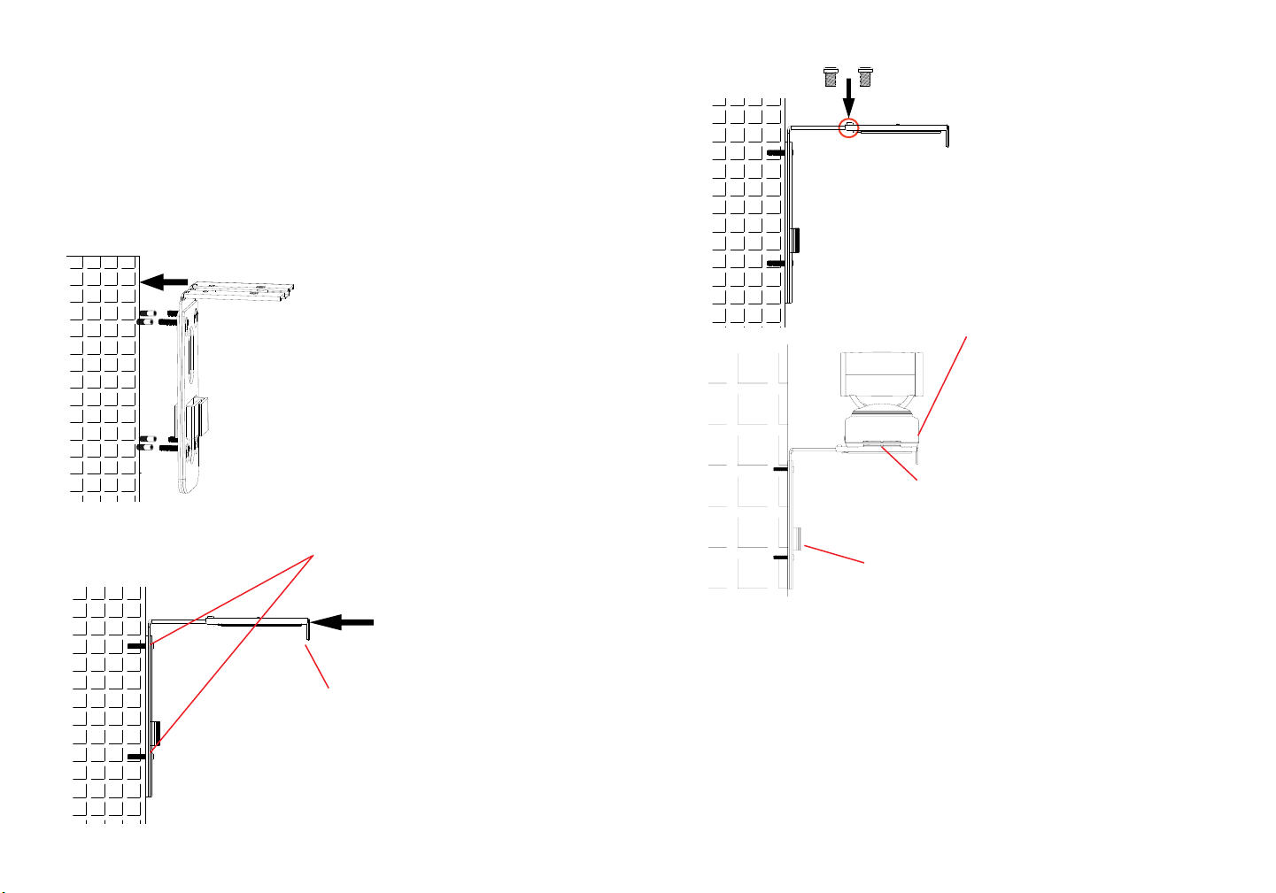
2. Na parte B do suporte de parede, há quatro furos para parafuso Tipo 3. Alinhe
a Parte B contra a parede onde você gostaria de colocar o suporte de parede.
3. De acordo com a posição dos quatro furos na parte B, localizar os pontos
correspondentes sobre a parede e perfure os furos.
4. Coloque as quatro buchas roscadas em cada buraco na parede. Por favor,
assegure que o lado lustroso é colocado para fora. Veja a gura abaixo.
5. Monte o suporte de parede Parte B
na parede. Em seguida, coloque os
quatro parafusos tipo 3 em cada
bucha roscada.
6. Aperte os parafusos para que a
Parte B possa ser rmemente
colocada contra a parede.
8. Alinhar partes A e B nos dois
furos conforme destacado abaixo.
Em cada buraco monte um
parafuso Tipo 2 e aperte-os.
9. Coloque o GVC3200 no topo do
suporte de parede Parte A. Encaixe
o pino de xação no orifício na parte
inferior do GVC3200.
10. Aperte o parafuso integrante do suporte
de parede Parte A para garantir que o
GVC3200 que rmemente encaixado.
11. Ajuste a cablagem com o prendedor de gancho e
laço na Parte B do suporte de parede.
CONNECTANDO O GVC3200:
1. Conecte a porta LAN do GVC3200 à tomada RJ-45 de um hub / switch ou roteador
(Lado LAN) através do cabo Ethernet.
7. Deslize o suporte de parede Parte A
ao encontro da Parte B, como indica
a seta acima.
2. Ligue a porta HDMI [1] do GVC3200 à porta HDMI do principal dispositivo de
visualização (por exemplo, TV) com o cabo HDMI. Conecte a porta HDMI 2 e,
em seguida, porta HDMI 3 se você tiver dispositivos de exibição adicionais.
Nota: Por favor, certique-se de seguir a ordem 1, 2 e 3 ao conectar portas HDMI.
O GVC3200 não vai funcionar corretamente se conectar as portas HDMI 2 ou 3 se
a porta 1 não estiver conectada.
3. Conecte o cabo USB do alto-falante na porta “SPKR” do GVC3200.
83 84
Page 45

Nota: Não conectar a porta “USB” do GVC3200 a um alto-falante. Conectar
alto-falante a porta “USB” pode fazer o alto-falante operar de forma inadequada.
4. Ligue a cha de saída de 12V DC ao conector de energia no GVC3200; conecte
o adaptador de alimentação a uma tomada elétrica.
6. Insira cartão SD na ranhura respectiva. Os arquivos de gravação serão salvos
nele.
7. (Opcional) Ligue um dispositivo de apresentação (por exemplo, um laptop) na
porta HDMI IN ou VGA IN do GVC3200 para ns de apresentação durante uma
conferência.
8. (Opcional) Ligue acessório USB (por exemplo, mouse, teclado, drive USB ash
e etc) à porta USB.
Exemplo de ligação:
Conecte o alto-falante externo à porta
GVC3200 SPKR. Utilize o cabo de extensão USB que acompanha o pacote,
se necessário.
VGA IN
HDMI IN HDMI OUT
Portas1/2/3
Entrada
para cartão
Porta
SPEAKER
Porta
USB
Ligação à terra
DC-IN 12VPorta
LAN
SD
5. O OLED de frente do GVC3200 exibirá informações de inicialização. Antes de
continuar, aguarde pela exibição do endereço IP no OLED. O dispositivo de
visualização (por exemplo, TV) também vai mostrar o endereço IP na barra de
status superior do ecrã inicial de repouso.
Lentes
OLED. Mostra o endereço
IP após inicialização.
Por exemplo,
Indicador LED
IP: 192.168.40.123
Conecte o cabo Ethernet da
porta LAN do GVC3200 no hub
/ switch / roteador (lado LAN).
Adaptador de
Conecte o cabo HDMI
entre a porta HDMI IN
do GVC3200 e a porta
HDMI do laptop. Isto é
para apresentação.
Conecte o cabo HDMI a partir da porta HDMI OUT 1 do
GVC3200 HDM à porta HDMI
da TV.
corrente 12V
DC está ligado
na tomada.
Nota:
Para obter mais informações sobre como instalar e ligar o GVC3200, por favor
visite a página web do produto GVC3200 de http://www.grandstream.com/support
85 86
Page 46

UTILIZAÇÃO DO CONTROLE REMOTO DO GVC3200:
Trackpad
Volume para Cima
Volume para Baixo
VOLTAR
Mute/DND
OK
PIP
Teclado padrão
* / Gravar
Enviar / Resposta /
Adicionar Participante
à Conferência
Retrocesso
1. Abra a tampa da bateria na parte traseira do controle remoto. Coloque
corretamente duas pilhas AAA e coloque de novo a tampa traseira.
2. Ao utilizar o GVC3200 pela primeira vez, o comando à distância deve ser emparelhado
e ligado a ele através de Bluetooth. Após o GVC3200 se encontrar totalmente
inicializado, toque no botão OK no controle remoto para iniciar a conexão. Em
seguida, o comando à distância pode ser utilizado normalmente.
Se o controle remoto não estiver emparelhado com o GVC3200 mais (por exemplo, se um reset de fábrica for feito), siga os passos abaixo para emparelhar e
ligar o controle remoto:
1. Conecte um mouse USB à porta USB GVC3200. Ou, faça o login na interface
do usuário GVC3200 web e clique em “Controle Remoto” no canto superior
direito para abrir o controle remoto virtual.
2. Use o mouse USB ou o controle remoto virtual para navegar para a tela de repouso
Menu> Congurações> Rede-> Bluetooth na TV.
3. Selecione o menu e clique em “Procurar dispositivos”.
4. No controle remoto, pressione a tecla OK e a tecla número 5 botão simultaneamente
por cerca de 4 segundos. Isto irá iniciar o processo de emparelhamento no
controle remoto.
INICIO
Zoom In
Zoom Out
Menu
Câmera
Teclas de Navegação:
Cima / Baixo /
Esquerda / Direita
Apresentação
Teclas de atalho:
Vermelho /
amarelo / azul
# / Informações
Terminar Chamada /
Remover Participante
da Conferência
Power ON / OFF
5. O controle de endereço MAC remoto irá mostrar na nova lista dispositivo em
sua TV. Selecione-o e ele vai ser emparelhado e ligado ao GVC3200 em breve.
Nota:
1. Os usuários também podem baixar GVC3200 Bluetooth app de controle remoto para
Android™ e instalar para o seu dispositivo Android™. Esta aplicação pode ser
usado como uma alternativa para o controlo remoto no pacote GVC3200.
2. Para obter mais informações sobre como usar o controle remoto Bluetooth do
GVC3200 para Android ™, consulte o manual do usuário GVC3200:
http://www.grandstream.com/support
CONFIGURAÇÃO DO GVC3200 VIA WEB UI:
1. Certique-se que o seu GVC3200 está devidamente ligado e conectado à
Internet.
2. O OLED na frente do GVC3200 vai mostrar o endereço IP do GVC3200 . Ele
também irá ser mostrado na parte superior da barra de status do dispositivo de
vídeo conectado (por exemplo, TV) via HDMI.
3. Digite o endereço IP no navegador do seu PC (veja a gura abaixo).
4. O nome de usuário e a senha do administrador padrão são “admin” e “admin”.
O nome de usuário e a senha padrão para o usuário são “usuário” e “123”.
5. Na web GUI, selecione Congurações> Conta-> página de Congurações
gerais para congurar o nome da conta, servidor SIP, Usuário SIP ID, ID para
autenticação e senha de autenticação para registrar a conta no GVC3200.
6. As congurações de rede podem ser conguradas na web UI-> Congurações>
página de Congurações de Rede; Congurações de controle PTZ e Preset
podem ser acessados sob UI- web> Dispositivo Controle-> página de Controle
de vídeo.
7. Por favor, entre em contato com o seu ITSP (Internet Telephony Service
Provider) para congurações adicionais que podem ser necessárias para
congurar o GVC3200.
Nota: Para o manual do usuário detalhado, faça o download desde:
http://www.grandstream.com/support
87 88
Page 47

PL
ZAWARTOŚĆ OPAKOWANIA:
Urządzenie GVC3200 nie jest wstępnie skongurowane do
obsługi lub wykonywania połączeń alarmowych do szpitali, or-
Zasilacz
Przewód zasilający
ganów ochrony porządku publicznego, jednostek opieki medycznej (zwanych dalej „służbami ratunkowymi”) ani jakichkolwiek
innych służb ratunkowych. Aby uzyskać dostęp do służb ratunkowych, konieczne jest wprowadzenie dodatkowych ustawień.
Użytkownik jest odpowiedzialny za zakup usług telefonii internetowej zgodnej z protokołem SIP, odpowiednią kongurację
1 X główne urządzenie GVC3200
1 X zestaw z zasilaczem 12 V
urządzenia GVC3200 umożliwiającą korzystanie z tej usługi
oraz okresowe testy konguracji w celu sprawdzenia, czy działa
ona zgodnie z oczekiwaniami. W przypadku niewykonania tych
czynności użytkownik jest odpowiedzialny za zakup tradycyjnych
bezprzewodowych lub przewodowych usług telefonicznych
w celu uzyskania dostępu do służb ratunkowych.
1 X pilot
1 X przewód HDMI (1.5m)
2 X przewód HDMI (3m)
1 X przewód HDMI (5m)
1 X kabel Ethernet
(1.5m)
1 X przedłużacz USB
(5m)
FIRMA GRANDSTREAM NIE ZAPEWNIA MOŻLIWOŚCI
POŁĄCZENIA ZE SŁUŻBAMI RATUNKOWYMI ZA
POŚREDNICTWEM URZĄDZENIA GVC3200. FIRMA GRAND-
STREAM, JEJ KIEROWNICTWO, PRACOWNICY ANI POD-
+
-
-
+
MIOTY STOWARZYSZONE NIE MOGĄ BYĆ POCIĄGNIĘTE
DO ODPOWIEDZIALNOŚCI Z TYTUŁU JAKICHKOLWIEK
ROSZCZEŃ, SZKÓD LUB STRAT, A UŻYTKOWNIK NINIEJSZYM
2 X AAA
akumulator
1 X Osłona
Obiektywu
1 X Ściereczka do
czyszczenia obiektywu
ZRZEKA SIĘ WSZELKICH TEGO TYPU ROSZCZEŃ I PODSTAW POWÓDZTWA WYNIKAJĄCYCH LUB POWIĄZANYCH
Z NIEMOŻNOŚCIĄ UŻYCIA URZĄDZENIA GVC3200 W CELU
NAWIĄZANIA KONTAKTU ZE SŁUŻBAMI RATUNKOWYMI I
NIEWPROWADZENIEM DODATKOWYCH
USTAWIEŃ UMOŻLIWIAJĄCYCH UZYSKANIE DOSTĘPU DO
SŁUŻB RATUNKOWYCH ZGODNIE Z INFORMACJAMI W
POPRZEDNIM AKAPICIE.
2 x śruby
typu 1
4 x śruby
typu 3
Uwaga: uwzględniono 1 zestaw zewnętrznych głośników do użycia z
urządzeniem GVC3200.
2 x śruby
typu 2
1 x instrukcja szybkiej
instalacji/
1 x licencja GPL
4 x kołki dla
śrub typu 3
1 x wspornik do montażu
ściennego (z częścią A i
częścią B przymocowanymi
do siebie)
89 90
Page 48

ŚRODKI OSTROŻNOŚCI:
OSTRZEŻENIE: korzystaj wyłącznie z zasilacza dostarczonego w opakowaniu
urządzenia GVC3200. Korzystanie z innego, nieodpowiedniego zasilacza może
spowodować uszkodzenie urządzenia.
OSTRZEŻENIE: NIE wyłączaj i nie włączaj ponownie urządzenia GVC3200 podczas uruchamiania systemu lub aktualizacji oprogramowania układowego. Może to
spowodować uszkodzenie obrazów oprogramowania układowego i nieprawidłową
pracę urządzenia.
OPIS URZĄDZENIA:
Urządzenie GVC3200 oferuje rmom rewolucyjny system do wideokonferencji, który
jest wyjątkowo elastyczny i domyślnie obsługuje wiele popularnych protokołów do konferencji wideo. Urządzenie GVC3200 działa w oparciu o system Android 4.4™ i oferuje
pełny dostęp do wszystkich aplikacji do wideokonferencji w sklepie Google Play™, takich jak Skype™, Skype for Business™, Google Hangouts™ i inne, a także wiodącej
w branży, opartej na protokole SIP platformy do wideokonferencji rmy Grandstream.
Urządzenie GVC3200 wyznacza nowy standard w wideokonferencjach dla rm pod
względem elastyczności, zdolności do współpracy z innymi urządzeniami, otwartości
systemu, bogactwa aplikacji oraz łatwości użycia w dobie Internetu.
INSTALACJA:
Urządzenie GVC3200 można zainstalować na trzy następujące sposoby:
Opcja 1: Umieszczenie na pulpicie.
Opcja 2: Mocowanie na telewizorze/monitorze. Wymagany jest wspornik do
montażu ściennego.
Opcja 3: Mocowanie na ścianie. Wymagany jest wspornik do montażu ściennego.
Wspornik do montażu ściennego jest dostarczany jako jeden element. Można go
rozdzielić na dwie części, rozsuwając/wypychając Część A z Części B.
Wysuń lub wypchnij Część A
Wbudowana śruba
INSTALACJA WSPORNIKA DO MONTAŻU URZĄDZENIA
GVC3200 NA TELEWIZORZE/MONITORZE:
1. Znajdź wspornik do montażu ściennego w opakowaniu i zidentykuj Część A i
Część B. NIE odłączaj Części A od Części B w przypadku montażu wspornika
na telewizorze.
2. Umieść urządzenie GVC3200 na górze Części A wspornika do montażu
ściennego. Patrz ilustracja poniżej. Trzpień ustalający Części A powinien
znaleźć się w otworze na dole urządzenia GVC3200.
3. Dokręć wbudowaną śrubę na
Części A wspornika do montażu
ściennego, aby zagwarantować,
że urządzenie GVC3200 jest
solidnie zamontowane.
Część A
Część B
Blokada
silikonowa
Trzpień
ustalający
4. Zamontuj wspornik do montażu
ściennego na górze telewizora od
tylnej jego strony. Przesuwaj ostrożnie
Część B wspornika do montażu
ściennego w Części A w celu
wyregulowania odstępu, tak aby
wspornik przylegał odpowiednio do
telewizora.
91 92
Page 49

5. Zamocuj śrubę typu 1 w każdym z
dwóch otworów w Części B, jak
pokazano po prawej stronie.
2. Na Części B wspornika do montażu ściennego znajdują się cztery otwory na
śruby typu 3. Dopasuj Część B do ściany w miejscu, w którym ma być
umieszczony wspornik.
3. Znajdź odpowiednie miejsca na ścianie zgodnie z położeniem czterech otworów
w Części B i wywierć je.
4. Umieść jeden z czterech kołków w każdym otworze w ścianie. Upewnij się, że
połyskliwa strona znajduje się na zewnątrz. Patrz rysunek poniżej.
2 x śruby
typu 1
6. Poprowadź wiązkę kabli po Części B wspornika do montażu ściennego przy
użyciu przylepcorzepów.
INSTALACJA WSPORNIKA DO MONTAŻU
URZĄDZENIA GVC3200 NA ŚCIANIE:
1. Znajdź wspornik do montażu ściennego w opakowaniu i zidentykuj Część A i
Część B. Odłącz Część A od Części B, wysuwając Część A.
Wbudowana śruba
Wysuń Część A
Część A
Trzpień ustalający
Cztery otwory
dla mocowania
ściennego przy
użyciu śrub typu 3
Część B
Blokada
silikonowa
5. Zamontuj Część B wspornika do
montażu ściennego do ściany.
Następnie umieść każdą z czterech
śrub typu 3 w odpowiednim kołku.
6. Dokręć śruby, tak aby Część B była
solidnie przymocowana do ściany.
7. Wsuń Część A wspornika do
montażu ściennego do Części B, jak
wskazuje strzałka powyżej.
9493
Page 50

8. Wyrównaj Część A i Część B w
miejscu 2 otworów zaznaczonych
poniżej. Zamocuj śrubę typu 2 w
każdym otworze i dokręć ją.
9. Umieść urządzenie GVC3200
na Części A wspornika do montażu
ściennego. Trzpień ustalający w
Części A wspornika do montażu
ściennego powinien być
dopasowany do otworu w dolnej
części urządzenia GVC3200.
Uwaga: Port USB w urządzeniu GVC3200 nie służy do podłączania głośnika.
Podłączenie głośnika do portu USB możne spowodować nieprawidłową pracę
głośnika.
4. Podłącz wtyczkę wyjściową 12 V DC do gniazda zasilania w urządzeniu
GVC3200; podłącz zasilacz do gniazda elektrycznego.
Wejście VGA
Uziemienie
10. Dokręć wbudowaną śrubę na Części
A wspornika do montażu ściennego, aby
zagwarantować, że urządzenie GVC3200
jest solidnie zamontowane.
11. Poprowadź wiązkę kabli po Części B wspornika
do montażu ściennego przy użyciu
przylepcorzepów.
PODŁĄCZENIE URZĄDZENIA GVC3200:
1. Przy użyciu kabla Ethernet połącz port LAN w urządzeniu GVC3200 z gniazdem
RJ-45 koncentratora/przełącznika lub routera (strona LAN w routerze).
2. Przy użyciu kabla HDMI połącz port HDMI [1] urządzenia GVC3200 z portem
HDMI głównego urządzenia do wyświetlania (np. telewizora). W przypadku
konguracji z dodatkowymi urządzeniami do wyświetlania podłącz również
porty HDMI 2 i HDMI 3.
Uwaga: Upewnij się, że przestrzegasz kolejności portów podczas łączenia portów
HDMI 1, 2 i 3. Urządzenie GVC3200 nie będzie działać poprawnie w przypadku
połączenia portu HDMI 2 lub 3 bez połączenia portu HDMI 1.
3. Podłącz kabel USB głośnika do portu SPKR w urządzeniu GVC3200.
Wejście
HDMI
5. Na wyświetlaczu OLED z przodu urządzenia GVC3200 w trakcie uruchamiania
będą wyświetlane informacje. Przed kontynuacją poczekaj na wyświetlenie
informacji o adresie IP na wyświetlaczu OLED. Na urządzeniu do wyświetlania
(np. telewizor) wyświetlany będzie również ekran główny z adresem IP na pasku
stanu.
Port
wyjściowy
HDMI 1/2/3
Obiektyw
Wyświetlacz OLED.
Po uruchomieniu
wyświetlana jest na
nim informacja o
adresie IP. Na przykład:
192.168.40.123
Gniazdo
karty SD
Port
głośnika
Port USB
Port LAN
Kontrolka LED
Wejście
prądu
stałego 12 V
95 96
Page 51

6. Włóż kartę SD do gniazda na kartę SD. Pliki nagrań będą zapisywane na karcie
SD.
7. (Opcjonalnie) Podłącz urządzenie do wyświetlania prezentacji (np. komputer
KORZYSTANIE Z PILOTA DO URZĄDZENIA GVC3200:
Panel dotykowy
Menu główne
przenośny) do portu HDMI IN lub VGA IN urządzenia GVC3200, aby wyświetlać
prezentację podczas konferencji.
8. (Opcjonalnie) Podłącz akcesorium USB (np. mysz, klawiaturę, pamięć USB itp.)
Głośność +
Powiększenie
do portu USB.
Przykład połączenia:
Podłącz kablem HDMI
port HDMI IN urządzenia
GVC3200 z portem
HDMI w komputerze
przenośnym. Służy to do
wyświetlania prezentacji.
Podłącz zewnętrzny głośnik
do portu SPKR urządzenia
GVC3200. Jeśli to konieczne,
użyj przedłużacza USB dostarc-
zonego w opakowaniu.
Połącz kablem Ethernet
port LAN urządzenia
GVC3200 z koncentra-
torem/przełącznikiem/
routerem (strona LAN).
Zasilacz prądem
stałym 12 V jest
podłączony do
gniazda.
Głośność -
Wstecz
Wyciszenie/nie
przeszkadzać
OK
Funkcja obraz
w obrazie
Standardowa
klawiatura
*/nagrywanie
Wysyłanie/odbieranie/
dodawanie osoby do
konferencji
Klawisz Backspace
1. Otwórz pokrywę baterii z tyłu pilota. Umieść odpowiednio dwie baterie AAA i
ponownie załóż pokrywę.
2. Pilot powinien być sparowany i połączony z urządzeniem GVC3200 za
pośrednictwem łączności Bluetooth już przy pierwszym użyciu. Gdy urządzenie
GVC3200 będzie w pełni uruchomione, dotknij przycisku OK na pilocie, aby
nawiązać połączenie. Wówczas można normalnie używać pilota.
Jeśli pilot nie jest już sparowany z urządzeniem GVC3200 (np. wykonano reset do
ustawień fabrycznych), wykonaj następujące czynności, aby sparować i połączyć
Pomniejszenie
Menu
Aparat
Klawisze nawigacyjne:
Góra/dół/lewo/prawo
Prezentacja
Klawisze skrótu:
Czerwony/żółty/
niebieski
#/informacja
Zakańczanie
połączenia/wyłączenie
osoby z konferencji
Włączanie/wyłączanie
pilota:
Połącz kablem HDMI port HDMI
OUT 1 urządzenia GVC3200 z
portem HDMI w telewizorze.
1. Podłącz mysz USB do portu USB urządzenia GVC3200. Możesz również
zalogować się do interfejsu sieciowego urządzenia GVC3200 i kliknąć opcję
Remote Control (Pilot) w prawym górnym rogu w celu uruchomienia wirtualnego
pilota.
2. Przy użyciu myszy USB lub wirtualnego pilota przejdź na telewizorze do ekranu
Uwaga:
Więcej informacji o instalacji i podłączaniu urządzenia GVC3200 można znaleźć
na stronie internetowej produktu GVC3200 pod adresem
http://www.grandstream.com/support
Menu->Settings (Ustawienia)->Network (Sieć)->Bluetooth.
3. Wybierz opcję MENU i kliknij opcję Search for devices (Wyszukaj
urządzenia).
4. Na pilocie naciśnij jednocześnie przycisk OK i przycisk numer 5 przez około 4
sekundy. Spowoduje to uruchomienie procesu parowania na pilocie.
97 98
Page 52

5. Adres MAC pilota zostanie wyświetlony na liście urządzeń na telewizorze.
Wybierz go. Po chwili pilot zostanie sparowany i połączony z urządzeniem
GVC3200.
Uwaga:
1. Użytkownicy mogą również pobrać aplikację pilota Bluetooth do urządzenia
GVC3200 dla systemu Android™ i zainstalować ją na urządzeniu z systemem
Android™. Tej aplikacji można używać jako alternatywy dla pilota dostarczonego
z urządzeniem GVC3200.
2. Więcej informacji o tym, jak korzystać z aplikacji pilota Bluetooth do urządzenia
GVC3200 dla systemu Android™, znajduje się w instrukcji obsługi urządzenia
GVC3200: http://www.grandstream.com/support
KONFIGURACJA URZĄDZENIA UCM6510 ZA
POŚREDNICTWEM SIECIOWEGO GRAFICZNEGO
INTERFEJSU UŻYTKOWNIKA:
1. Sprawdź, czy urządzenie GVC3200 jest właściwie podłączone do Internetu i
włączone.
2. Adres IP urządzenia GVC3200 będzie wyświetlany na wyświetlaczu OLED z
przodu urządzenia GVC3200. Będzie on również wyświetlany na górnym pasku
stanu podłączonego kablem HDMI urządzenia do wyświetlania (np. telewizora).
3. Wpisz adres IP w przeglądarce na komputerze (patrz rysunek poniżej).
4. Domyślna nazwa użytkownika i hasło dla administratora to „admin” i „admin”.
Domyślna nazwa użytkownika i hasło dla użytkownika to „user” i „123”.
5. W gracznym sieciowym interfejsie użytkownika wybierz kolejno opcje
Settings (Ustawienia)->Account (Konto)->General Settings (Ustawienia ogólne),
aby skongurować nazwę konta, serwer SIP, identykator użytkownika SIP,
identykator uwierzytelniania oraz hasło uwierzytelniania do rejestracji konta na
urządzeniu GVC3200.
6. Ustawienia sieciowe można skongurować w interfejsie użytkownika, wybierając
kolejno opcje Settings (Ustawienia)->Network Settings (Ustawienia sieciowe).
Dostęp do opcji PTZ Control (Sterowanie PTZ) i Preset Settings (Ustawienia
wstępne) można uzyskać, wybierając kolejno opcje Device Control (Sterowanie
urządzeniem)->Video Control (Sterowanie wideo) w interfejsie użytkownika.
7. Więcej informacji potrzebnych do skongurowania urządzenia GVC3200 można
uzyskać od dostawcy usług telefonii internetowej.
Szczegółową instrukcję obsługi można pobrać ze strony:
http://www.grandstream.com/support
99
 Loading...