

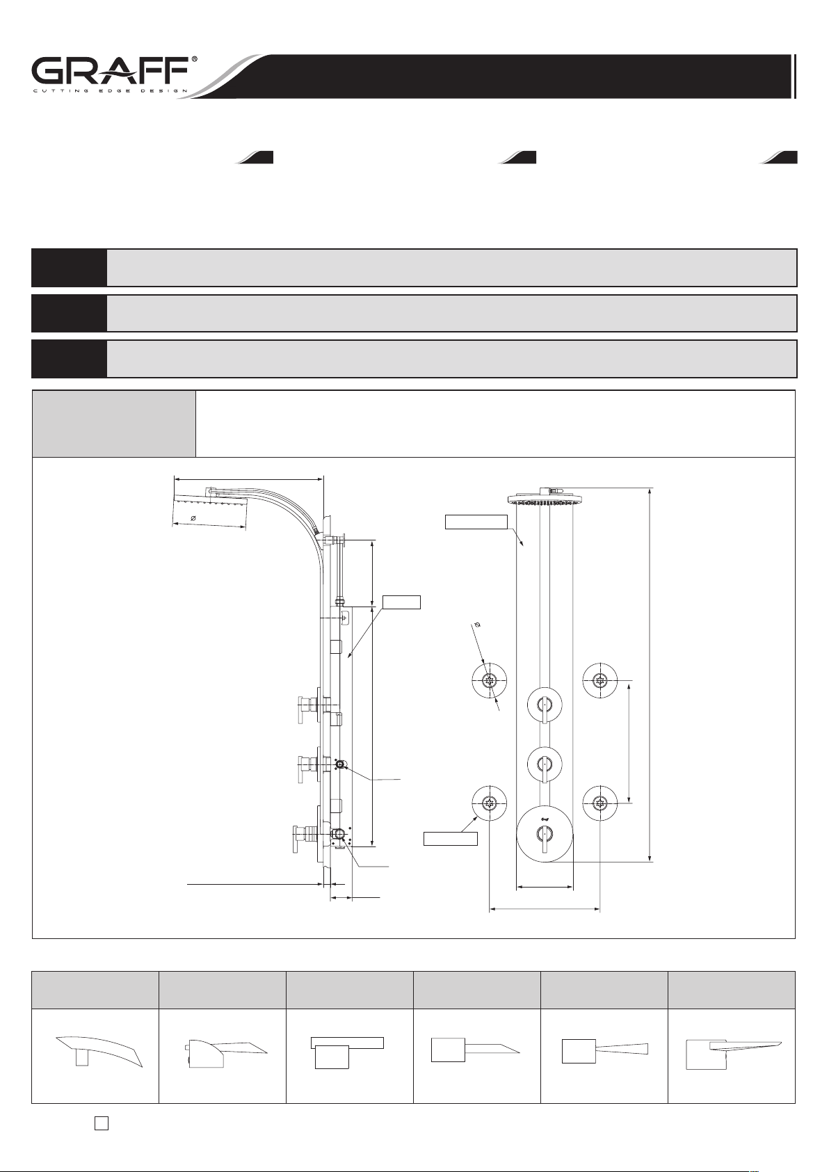
2321.00 (PC)
Zestaw ozdobny /bez dysz bocznych do natrysku ciała/ do naściennego, okrągłego panelu natryskowego
Trim set /without body sprays/ for wall-mount round showering panel
Jeu décoratif / sans buses latérales de massage / pour le panneau rond de douche,
à installer contre le mur
LM24S LM25B LM27S LM29B LM30B LM33S
Tranquility Atria Tango Eco Viva Kobe
Szanowny Kliencie
Dziękujemy za wybranie naszego wyrobu. Mamy pewność, że możemy w pełni zaspokoić Twoje oczekiwania
dzięki naszej bogatej ofercie wyrobów na wysokim poziomie technologicznym, który wynika z naszego wieloletniego doświadczenia na polu produkcji baterii i armatury.
Dear Customer
Thank you for selecting our product. We are confident
we can fully satisfy your expectations by offering you
a wide range of technologically advanced products which
directly result from our many years of ex perience in faucet and fitting production.
Cher Client!
Nous vous remercions pour savoir choisi notre produit.
Nous sommes certains de pouvoir satisfaire pleinement
à vos attentes grâce à notre riche offre de produits d’un
niveau technologique avancé qui résulte de notre longue expérience en fabrication de la robinetterie et des
accessoires des salles de bains.
Do pielęgnacji używać wyłącznie miękkiego ręcznika oraz mydła i wody! W żadnym wypadku nie należy używać żadnych środków chemicznych.
UWAGA!
For care, use soft towel with soap and water only! Under no circumstances should you use any chemicals.
ATTENTION!
Pour le nettoyage utiliser seulement une serviette douce, du savon et de l’eau! En aucun cas n’utiliser les produits chimiques quelconques!
ATTENTION!
IOG 2321.00
1
Rev.1 January 2007
A
Instrukcja Montażu i Obsługi
n
Instructions for assembly and use
n
Instrucción de Montaje y Servizio
Wall-mount thermostatic showering panel ED1.0, ED2.0
Panneaux de douche thermostatiques à installer contre le mur ED1.0, ED2.0
Naścienne termostatyczne panele natryskowe ED1.0, ED2.0
PL GB F
MAX. 24.5mm
Projektowa końcowa grubość ściany
Planned finished wall thickness
Epaisseur finale prévue de la paroi
2322.50
Rp 1/2"
Rp 3/4"
254mm
517mm
229mm
830mm
76mm
382mm
195mm
424mm
~1294mm
120mm
2321.00 (PC)
2322.00 (PC)
Możliwości wyboru różnych uchwytów / Different choice of levers available / Possibilités de choix de poignées diverses:
LM29B LM30B C4 LM33S
LM24S LM25B LM27S
LM23S C8S C9S C10S LM30B LM31S
Stealth Manhattan Immersion Fontaine Targa Solar
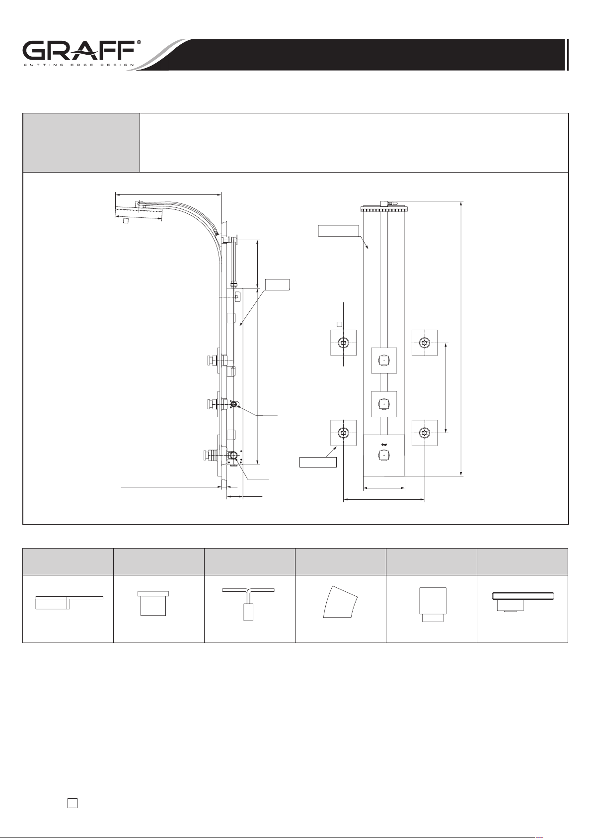
2321.50 (PC)
Zestaw ozdobny /bez dysz bocznych do natrysku ciała/ do naściennego, prostokątnego
panelu natryskowego
Trim set /without body sprays/ for wall-mount square showering panel
Jeu décoratif / sans buses latérales de massage / pour le panneau rectangulaire de douche,
à installer contre le mur
IOG 2321.00
2
Rev.1 January 2007
A
Wall-mount thermostatic showering panel ED1.0, ED2.0
Panneaux de douche thermostatiques à installer contre le mur ED1.0, ED2.0
Naścienne termostatyczne panele natryskowe ED1.0, ED2.0
MAX. 24.5mm
Projektowa końcowa grubość ściany
Planned finished wall thickness
Epaisseur finale prévue de la paroi
2322.50
Rp 3/4"
Rp 1/2"
120mm
~500mm
229mm
2321.50 (PC)
~1294mm
424mm
195mm
382mm
76mm
830mm
220mm
2322.25 (PC)
LM23S C4 C8S C9S C10S C14S LM31S
Możliwości wyboru różnych uchwytów / Different choice of levers available / Possibilités de choix de poignées diverses:
Instrukcja Montażu i Obsługi
n
Instructions for assembly and use
n
Instrucción de Montaje y Servizio
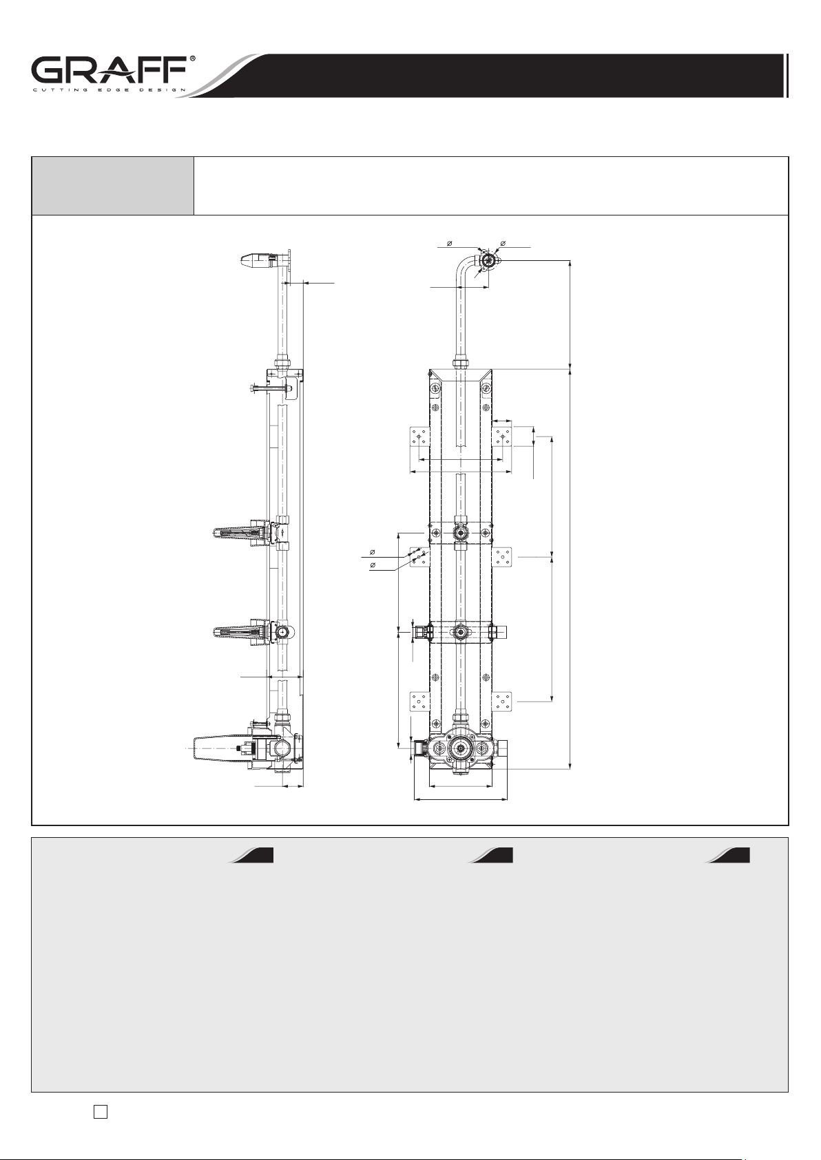
2322.50 (PC)
Kompletny zestaw z wbudowaną skrzynką montażową
Complete rough box set
Jeu complet avec la boîte de montage
IOG 2321.00
3
Rev.1 January 2007
A
43mm
3x 4.2mm
27mm
76mm
130mm
241mm
206mm
300mm
830mm
250mm
174.1mm
40.5mm
40.5mm
225mm
67mm
40mm
4x 5mm
6mm
Rp1/2"
193mm
Rp3/4"
211mm
Narzędzia i materiały:
•
Powszechnie stosowane narzędzia
i materiały stolarskie
•
Taśma miernicza
•
Ołówek
•
Wiertło
•
Śrubokręt płaski
•
Śrubokręt krzyżakowy
•
Sześciokątne klucze maszynowe
•
Poziomica
•
Silikonowy uszczelniacz
•
Termometr
Tools and Materials:
•
Conventional woodworking
Tools and materials
•
Tape measure
•
Pencil
•
Drill
•
Blade screwdriver
•
Philips screwdriver
•
Hex wrenches
•
Level
•
Silicone sealant
•
Thermometer
Outils et matériel:
•
Outils et matériel conventionnels
pour travailler le bois
•
Ruban de mesurage
•
Crayon
•
Foret
•
Tournevis plat
•
Tournevis à la pointe en forme
de croix de Philips
•
Clés hexagonales pour les machines
•
Nivelle
•
Joint de silicone
•
Thermomètre
PL GB F
Wall-mount thermostatic showering panel ED1.0, ED2.0
Panneaux de douche thermostatiques à installer contre le mur ED1.0, ED2.0
Naścienne termostatyczne panele natryskowe ED1.0, ED2.0
Instrukcja Montażu i Obsługi
n
Instructions for assembly and use
n
Instrucción de Montaje y Servizio
IOG 2321.00 4 Rev.1 January 2007
A
WYMAGANIA DOTYCZĄCE CIŚNIENIA WODY
Zalecamy dla optymalnego działania minimalne ciśnienie bieżącej wody 3 bar.
W przypadku instalacji, w których ciśnienie wody jest nieodpowiednie rozważyć zamontowanie pompy wspomagającej.
WATER PRESSURE REQUIREMENTS
For optimum performance, we recommend a minimum of 3 bar running water pressure.
For installations where the water pressure is inadequate, consider installing a booster pump.
EXIGENCES RELATIVES À LA PRESSION DE L’EAU
Pour le fonctionnement optimal nous recommandons la pression minimale de l’eau courante de 3 bars.
Dans les installations où la pression de l’eau n’est pas adéquate, réfléchissez à installer une pompe d’assistance.
PL
GB
F
ZASILANIE GORĄCĄ WODĄ
Maksymalna wielkość przepływu przez panel prysznicowy (przepływ jednocześnie przez 4 dysze boczne do masażu i głowicę prysznicową)
wynosi 37 l/min. przy ciśnieniu 3 bar. W przypadku zasilania panela w ciepłą wodę z pojemnościowego ogrzewcza wody należy pamiętać
o zapewnieniu właściwego wydatku ciepłej wody.
HOT WATER SUPPLY
Maximum flow rate through the shower panel (simultaneous flow through 4 body sprays and shower head) is 37 l/min. at the pressure 3 bar.
In case of hot water installation from hot water tank please make sure that there is a sufficient capacity of stored hot water to provide adequate hot
water flow from the shower panel.
ALIMENTATION EN EAU CHAUDE
La valeur maximum de l’écoulement de l’eau par le jeu de douche (l’écoulement par 4 buses latérales de massage et par la douchette) est de 37l/min.
avec la pression de 3 bars. Si la douche est alimentée en eau chaude d’une chaudière de l’eau, il ne faut pas oublier d’assurer une quantité appropriée
d’eau chaude.
PL
GB
F
OSTRZEŻENIE !
Ryzyko oparzenia lub innego poważnego obrażenia
Instalator musi przed ukończeniem montażu ustawić nastawę maksymalnej temperatury wody ciepłej tego zaworu, tak aby zminimalizować ryzyko
związane z niebezpieczeństwem oparzenia.
Ryzyko zniszczenia wyrobu
Do tych zaworów należy używać tylko smarów opartych na silikonie.
Użycie do tych zaworów smarów opartych na ropie naftowej szkodzi pierścieniom uszczelniającym o przekroju okrągłym, uszczelkom.
Użycie smarów opartych na ropie naftowej spowoduje unieważnienie gwarancji.
WARNING!
Risk of scalding or other severe injury
Before completing installation, the installer must set the maximum water temperature setting of this valve to minimize the risks associated with
scalding hazards.
Risk of product damage
Only silicone based lubricants should be used with these valves. Use of petroleum based lubricants on the valve is harmful to the O-rings, seals.
Use of petroleum based lubricants will void the warranty.
ATTENTION!
Risque de brûlure ou d’une autre lésion grave
Avant de terminer le montage, l’installateur doit ajuster la température maximale de l’eau chaude sur cette valve pour minimiser le risque de brûlure.
Risque de détérioration du produit
Sur ces valves il faut utiliser uniquement les lubrifiants à base de silicone.
L’emploi des lubrifiants à base de pétrole sur ces valves, détériore les o-rings et les joints. L’emploi des lubrifiants à base de pétrole impliquera l’annulation de la garantie.
PL
GB
F
Wall-mount thermostatic showering panel ED1.0, ED2.0
Panneaux de douche thermostatiques à installer contre le mur ED1.0, ED2.0
Naścienne termostatyczne panele natryskowe ED1.0, ED2.0
Instrukcja Montażu i Obsługi
n
Instructions for assembly and use
n
Instrucción de Montaje y Servizio
IOG 2321.00
5
Rev.1 January 2007
A
R16
R19
R17
R18
R1
R20 R21
R24
R2
R22
R10.1
R10.2
R10.3
R10.4
R9 R15
R10
R11
R12 R13 R14
R3
R4 R5
R6
R7
R8
R23
PRZYGOTOWANIE MIEJSCA
Przed przystąpieniem do montażu upewnij się, że docelowa wysokość pomieszczenia, w którym będzie zainstalowany panel nie może być mniejsza
niż 235cm. Dla bezpiecznej i trwałej instalacji upewnij się, że ściana w miejscu montażu jest odpowiednio wytrzymała. Zamontuj natrysk na płaskiej
powierzchni ściany.
PREPARE THE SITE
Before proceeding with installation make sure, that the final height of the room where the panel will be installed is not less than 235cm.
For a safe and durable installation, ensure that the wall at the installation location is adequately reinforced. Install the shower to a flat wall surface.
PRÉPARATION DE L’ENDROIT
Avant de procéder au montage, assurez-vous que la hauteur de la pièce où la douche sera installée n’est pas inférieure à 235 cm.
Pour une installation sure et durable, vérifiez si le mur à l’endroit du montage est bien renforcé. Installez la douche sur la surface plate du mur.
PL
GB
F
Wall-mount thermostatic showering panel ED1.0, ED2.0
Panneaux de douche thermostatiques à installer contre le mur ED1.0, ED2.0
Naścienne termostatyczne panele natryskowe ED1.0, ED2.0
Instrukcja Montażu i Obsługi
n
Instructions for assembly and use
n
Instrucción de Montaje y Servizio
1
IOG 2321.00
6
Rev.1 January 2007
A
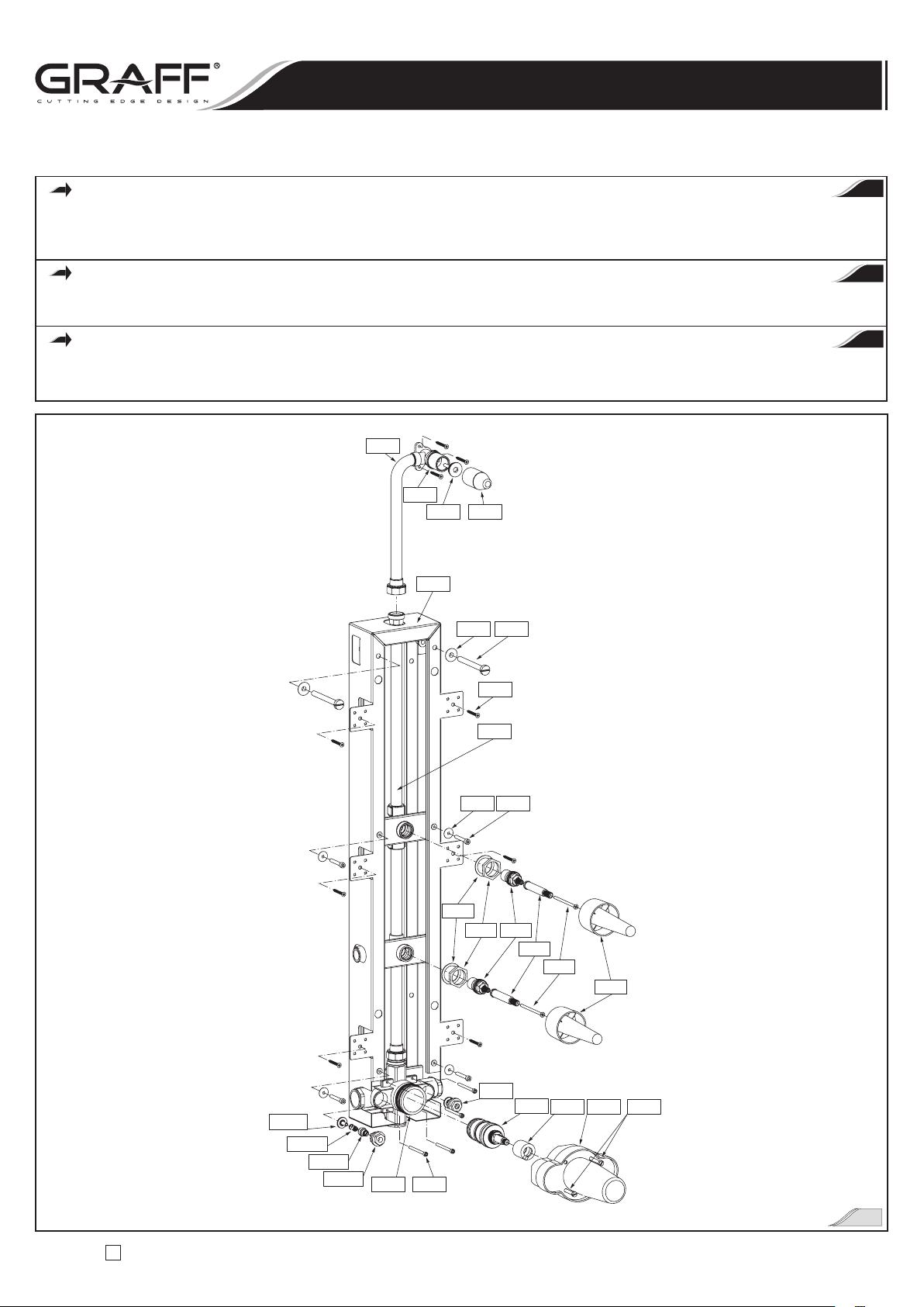
R1
Kompletna skrzynka montażowa Complete rough box Boite de montage complete
R2
Instalacja zasilająca wbudowana w skrzynkę
montażową
Supply installation of rough box
Installation d’alimentation de la boite de montage
incorporée
R3
Uszczelka (2 szt.) Washer (2 pcs) Joint (2 pièces)
R4
Nakrętka (2 szt.) Nut (2 pcs) Ecrou (2 pièces)
R5
Głowica ceramiczna 1/4 obrotu, otwierana
w lewo (2 szt.)
Ceramic cartridge 1/4 turn,
counterclockwise opening (2 pcs)
Tête en ceramique 1⁄4 de tour; s’ouvrant vers la
gauche (2 pièces)
R6
Złączka redukcyjna (2 szt.) Adapter (2 pcs) Adaptateur (2 pièces)
R7
Wkręt (2 szt.) Screw (2 pcs) Vis (2 pièces)
R8
Osłona montażowa zaworu zamykającego/
sterującego przepływem (2 szt.)
Plaster guard of stop/volume control valvem (2 pcs)
Carter de montage de la vanne d’arret/
d’ecoulement (2 pièces)
R9
Zawór termostatyczny 3/4” 3/4” Thermostatic valve Valve thermostatique 3⁄4’’
R10
Zawór zamykający (2 szt.) Stop valve (2 pcs) Vanne d’arret (2 pièces)
R10.1
Głowica zaworu Valve head Tete de la valve
R10.2
Sprężyna (2 szt.) Spring (2 pcs) Ressort (2 pièces)
R10.3
Trzpień obrotowy (2 szt.) Valve spindle (2 pcs) Mandrin de la valve (2 pièces)
R10.4
Pokrywa głowicy (2 szt.) Head cover (2 pcs) Carter de la tete (2 pièces)
R11
Wkład termostatyczny Thermostatic cartridge Cartouche thermostatique
R12
Pierścień ograniczający temperaturę Temperature limiting ring Bague de limitation de la temperature
R13
Osłona montażowa zaworu termostatycznego Plaster guard of thermostatic valve Carter de montage de la valve thermostatique
R14
Wkręt (2 szt.) Screw (2 pcs) Vis (2 pièces)
R15
Śruba (4 szt.) Bolt (4 pcs) Vis (4 pièces)
R16
Przedłużka rurowa do głowicy natryskowej
Pipe extension for the shower head Rallonge de la douchette
R17
Zaślepka Cap Bouchon
R18
Osłona montażowa Plaster guard Carter de montage
R19
Wkręt (3 szt.) Screw (3 pcs) Vis (3 pièces)
R20
Tuleja teflonowa śruby (2 szt.)
Bolt teflon sleeve (2 pcs) Cale en teflon du vis (2 pièces)
R21
Wkręt (2 szt.) Screw (2 pcs) Vis (2 pièces)
R22
Tuleja teflonowa śruby (2 szt.)
Bolt teflon sleeve (2 pcs) Cale en teflon du vis (2 pièces)
R23
Śruba (4 szt.) Bolt (4 pcs) Vis (4 pièces)
R24
Wkręt mocujący (6 szt.) Mounting screw (6 pcs) Vis de fixation (6 pièces)
PL GB F
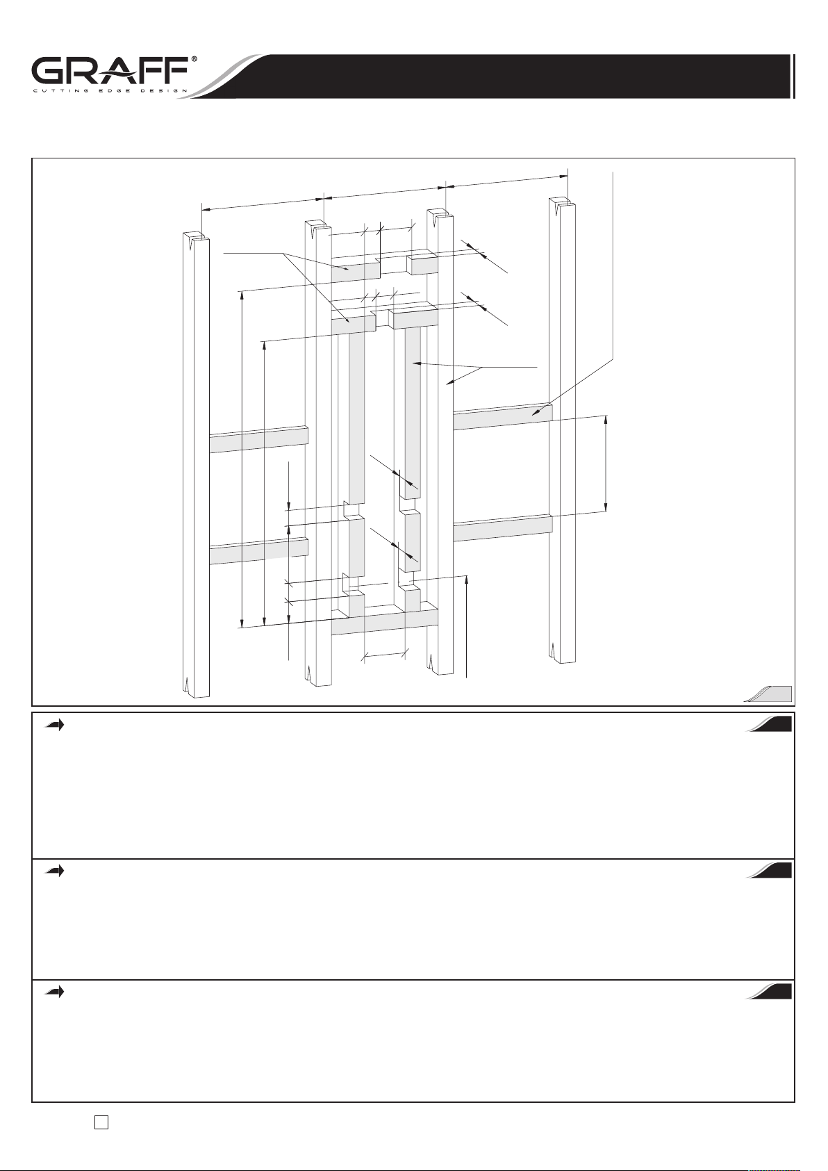
PRZYGOTOWANIE STELAŻU ŚCIANKI
Patrz rys. 2
•
Zbuduj konstrukcję pionową zgodnie z wymiarowymi wymaganiami potrzebnymi dla zabudowy Twojego natrysku.
•
W miejscu instalacji natrysku dodaj poziome elementy usztywniające o wymiarach 2x4” pomiędzy słupkami konstrukcji pionowej zgodnie z rys. 2.
Dla określenia położenia poziomych elementów usztywniających użyj wyliczonej wstępnie wysokości wykończonego brodzika.
•
Dodaj cztery cienkie poziome elementy usztywniające pomiędzy słupkami. Zestaw natryskowy nie zawiera kolanek doprowadzających wodę.
CONSTRUCT THE FRAMING
See fig. 2
THE FRAMING
•
Construct stud framing according to the dimensional requirements required for your shower enclosure.
•
At the shower installation location add 2x4” stringers horizontally between the studs according to fig. 2.
Use your estimated finished basin thickness to help determine the stringer locations.
•
Add four thin stringers horizontally between the studs forbody sprays supply elbows. Supply elbows are not included
with shower components.
CONSTRUTION DE L’ARMATURE DE LA PAROI
Voir fig. 2
•
Construisez l’armature verticale de la paroi, conformément aux dimensions requises de la paroi de votre douche.
•
Dans l’endroit de l’installation de la douche placez les barres horizontales de renforcement de dimensions de 2x4” entre les montants verticaux,
conformément au schéma sur la fig. 2. Pour déterminer l’emplacement des barres horizontales de renforcement, servez-vous de la valeur
calculée préalablement de la hauteur du bac.
•
Placez quatre barres fines de renforcement entre les montants. Le jeu de la douche ne comprend pas les coudes d’alimentation de l’eau.
PL
GB
F
Wall-mount thermostatic showering panel ED1.0, ED2.0
Panneaux de douche thermostatiques à installer contre le mur ED1.0, ED2.0
Naścienne termostatyczne panele natryskowe ED1.0, ED2.0
Instrukcja Montażu i Obsługi
n
Instructions for assembly and use
n
Instrucción de Montaje y Servizio
IOG 2321.00
7
Rev.1 January 2007
A
Poziome elementy usztywniające dla kolanek
doprowadzających wodę do bocznych dysz do masażu
Stringers for body sprays supply elbow
barres horizontales de renforcement pour les coudes
d’alimentation de l’eau aux buses latérales de massage
2"x4"
Poziome elementy
usztywniające
Stringers
Barres horizontales
de renforcement
1016mm
Zalecany wymiar od osi wlotów zaworu
termostatycznego do wykończonej posadzki
Recommended dimension from the axis of the
thermostatic valve inlets to the finished floor
Dimension recommandée entre l’axe des entrées
de la valve thermostatique et le carrelage fini
2"x4"
Konstrukcja pionowa
Stud framing
Construction verticale
186mm
501mm
61mm
70mm
921mm
1090mm
61mm
51mm
105mm
53mm
61mm
38mm
51mm
48mm
135mm
Zgodnie z Twoimi potrzebami
According to your needs
Conformément a vos besoins
407mm
407mm
407mm
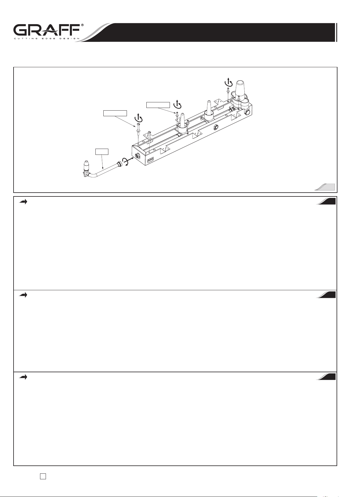
INSTALACJA SKRZYNKI MONTAŻOWEJ
Patrz rys. 1, 3 i 4
•
Przykręć łącznik zasilający głowicy natryskowej (R16) do górnego wylotu króćca rurowego skrzynki. Upewnij się, że pierścień samouszczelniający
o okrągłym przekroju jest we właściwej pozycji na końcu łącznika (R16). Dokręć nakrętkę mocującą za pomocą klucza nastawnego.
Nie dokręcaj zbyt mocno.
•
Odkręć cztery śruby z łbami gniazdowymi (R23) z podkładkami uszczelniającymi (R22) oraz dwie śruby z łbami płaskimi (R21)
podkładkami uszczelniającymi
(R20) i zachowaj je bezpiecznie do dalszego użytku.
•
Umieść skrzynkę montażową w przygotowanej drewnianej konstrukcji. Przymocuj skrzynkę do konstrukcji ścianki działowej za pomocą
załącznych wkrętów mocujących (R24) – stosuj się do rys. 4. W razie potrzeby konieczne użyj większej liczby wkrętów mocujących
do przytwierdzenia skrzynki.
ROUGH BOX INSTALLATION
See fig. 1, 3 & 4
•
Screw on the shower head supply connection (R16) to top outlet stub pipe of the box. Make sure that the o-ring seal is in proper position
at the end of connection (R16). Tighten the mounting nut using adjustable wrench. Do not over-tighten.
•
Unscrew the four socket head screws (R23) with sealing washers (R22) and the two flat head screws (R21) with sealing washers (R20) and keep
them save for lateruse.
•
Insert the complete rough box to wood framing prepared. Attach the box to stud framing using the mounting screws (R24) included –
refer to fig. 4. If necessary use more mounting screws to secure the box.
INSTALLATION DE LA BOÎTE DE MONTAGE
Voir fig. 1, 3 et 4
•
Vissez la rallonge de la douchette (R16) sur la sortie supérieure de la rallonge de la boîte. Assurez-vous si le joint de type o-ring est en bonne
position sur la rallonge
(R16). Serrez l’écrou de fixation avec la clé anglaise. Ne serrez pas trop fort.
•
Dévissez quatre vis à trou à six pans (R23), avec les cales de remplissage (R22) et deux vis à têtes plates (R21) avec les cales de remplissage
(R20) et gardez-les en sécurité pour l’emploi futur.
•
Placez la boîte de montage sur l’armature en bois construite préalablement. Fixez la boîte à l’armature de la paroi à l’aide des vis de fixation
qui fait partie du jeu (R24) – conformément à la fig. 4. Utilisez au besoin plus de vis de fixation pour fixer la boîte.
PL
GB
F
Wall-mount thermostatic showering panel ED1.0, ED2.0
Panneaux de douche thermostatiques à installer contre le mur ED1.0, ED2.0
Naścienne termostatyczne panele natryskowe ED1.0, ED2.0
Instrukcja Montażu i Obsługi
n
Instructions for assembly and use
n
Instrucción de Montaje y Servizio
2
IOG 2321.00
8
Rev.1 January 2007
A
Wall-mount thermostatic showering panel ED1.0, ED2.0
Panneaux de douche thermostatiques à installer contre le mur ED1.0, ED2.0
Naścienne termostatyczne panele natryskowe ED1.0, ED2.0
R22,R23
R20,R21
R16
INSTALACJA PRZYŁĄCZY WODY
UWAGA: Przed rozpoczęciem montażu upewnij się, że zasilanie wodą jest wyłączone.
Patrz rys. 4
Możliwe są różne kombinacje złączek redukcyjnych wkrętnych i kolanek. Wybierz kolanko i złączki redukcyjne wkrętne, które będą użyte
przed zakotwieniem przewodów zasilających w ścianie.
UWAGA: Zalecana wysokość od wyliczonej wstępnie górnej powierzchni wykończonej posadzki do osi wlotów zaworu termostatycznego wynosi
ok. 1 m lub jest dostosowana do Twoich wymagań.
•
Zamontuj 3/4” miedziane przewody doprowadzające wodę, kolanka 90° i złączki redukcyjne wkrętne zgodnie z rys. 4. Rozmieść instalację
wodną rur w taki sposób, aby przyłącze ciepłej wody było po lewej stronie
(CIEPŁA), a zimnej po prawej stronie (ZIMNA) zaworu
termostatycznego. Wloty zaworu termostatycznego mają gwint Rp 3/4” typu nakrętnego.
•
Przewody doprowadzające wodę do dyszy bocznych do natrysku ciała wychodzą po obydwu stronach wbudowanej skrzynki montażowej.
Przewody zasilające dysze boczne do natrysku ciała powinny być zakończone kolankami zasilającymi i złączkami redukcyjnymi wkrętnymi.
Zapewnij poprawny montaż kolanek na cienkich poziomych elementy usztywniających. Zalecana odległość od lica kolanka wkrętnego
doprowadzającego wodę do lica konstrukcji ścianki działowej wynosi około 35mm. Wyloty zaworu zamykającego/sterującego przepływem
mają gwint stożkowy Rp 1/2” typu nakrętnego.
INSTALL THE WATER SUPPLIES
NOTE: Make sure that the water supply is off before start of installation.
See fig. 4
Various combinations of male adapters and elbows are possible. Plan for the elbow and male adapters that will be used before anchoring the supply
tubes inside the wall.
NOTE: Recommended height dimension from the estimated top of the finished floor to the therm valve inlets axis is about 1 meter
or your height preference.
•
Install 3/4” copper water supply lines, 90° elbows, and male adapters according to the roughing-in information – refer to fig.4. Arrange the pipe
work so that the hot water feed is on the left
(HOT) and cold is on the right (COLD) in relation to the therm valve. Therm valve inlets are
Rp 3/4” female.
•
From both sides of rough box run the supply lines to feed body sprays. The supply lines for body sprays should end with supply elbows
and male adapters. Make sure to install the elbows correctly at the thin stringers. Recommended distance from face of the male supply elbow
to face of the stud framing is about 35mm. Stop/volume control valve outlets are Rp 1/2” female.
ACCOUPLEMENT DE L’ALIMENTATION DE L’EAU
ATTENTION: Avant de commencer le montage, assurez-vous si l’alimentation en eau est coupée
Voir fig. 4
Il existe de nombreuses combinaisons des réductions mâles et des coudes. Choisissez un coude et des réductions mâles qui seront utilisés avant la
fixation des tuyaux d’alimentation dans le mur.
NOTE: La distance recommandée entre la valeur calculée de la surface supérieure du carrelage achevé et l’axe des entrées à la valve thermostatique
est de 1 m environ ou selon vos besoins.
•
Installez les tuyaux d’alimentation en eau 3⁄4” en cuivre, les coudes de 90° et les réductions mâles, conformément à la fig. 4. Installez les tuyaux
de telle manière à ce que l’alimentation en eau chaude soit du côté gauche (CHAUDE) et celle en eau froide – du côté droit (FROIDE)
de la valve thermostatique. Les entrées de la valve thermostatique ont le filetage intérieur conique pour les tubes Rp 3⁄4”.
•
Les tuyaux d’alimentation des buses latérales de massage en eau sortent des deux côtés de la boîte de montage incorporée. Les tuyaux
d’alimentation des buses latérales de massage en eau doivent avoirs les coudes d’alimentation et des réductions mâles sur leurs extrémités.
Assurez un bon montage des coudes sur les barres horizontales de renforcement. La distance recommandée entre la face du coude mâle
d’alimentation en eau et la face de l’armature de la paroi est de 35mm environ. Les sorties de la vanne d’arrêt / d’écoulement ont le filetage
intérieur conique pour les tubes Rp1⁄2”.
PL
GB
F
Instrukcja Montażu i Obsługi
n
Instructions for assembly and use
n
Instrucción de Montaje y Servizio
3

IOG 2321.00
9
Rev.1 January 2007
A
Wall-mount thermostatic showering panel ED1.0, ED2.0
Panneaux de douche thermostatiques à installer contre le mur ED1.0, ED2.0
Naścienne termostatyczne panele natryskowe ED1.0, ED2.0
35mm
HO
T
Wykończona powierzchnia ściany
Finished wall surface
Surface du mur finie
COLD
MIN. 305mm
Wykończony sufit
Finished ceiling
Plafond fini
Uwaga!
W celu zapewnienia właściwego montażu
zestawu natryskowego wymagana minimalna
odległość od wykończonego sufitu do osi
kolanka zasilającego głowicę natryskową
wynosi 305mm
Caution:
A minimum distance of 305mm from
finished ceiling too the axis of shower head
supply elbow is required to insure proper fit
of trim package.
Note:
Pour assurer un montage correct du jeu de
douche, la distance minimum requise entre
le plafond fini et l’axe du coude d’alimentation
de la douchette est de 305mm
PRÓBA SZCZELNOŚCI POŁĄCZEŃ
Patrz rys. 5
•
Zaślep przewody zasilające dysze boczne do natrysku ciała. Usuń osłonę montażową (R18) przez obrócenie i ściągnięcie, i upewnij się,
że kolanko zasilające głowicę natryskową jest fabrycznie zaślepione specjalnym korkiem (R17).
•
Usuń osłony montażowe (R8) przez obrócenie i ściągnięcie. Ustaw zawór zamykający/sterujący przepływem w pozycji otwartej „ON” – w tym
przypadku obróć przedłużkę wieloklinu zaworu maksymalnie w kierunku przeciwnym do kierunku ruchu wskazówek zegara (w lewo).
•
Odkręć dwa długie wkręty (R14) przy pomocy śrubokręta płaskiego. Usuń również osłonę montażową zaworu termostatycznego (R13).
•
Włącz zasilanie wodą i sprawdź czy występują przecieki.
•
Wyłącz wodę.
LEAK TEST OF THE CONNECTIONS
See fig. 5
•
Cap the supplies of body sprays. Remove plaster guard (R18) by turning and pulling and make sure that the shower head supply elbow is factory
plugged by special plug
(R17) included.
•
Remove plaster guards (R8) by turning and pulling. Position stop/volume control valves at open “ON” position – in this case turn valve spline
elongations max. counterclockwise direction.
•
Unscrew two long screws (R14) using blade screwdriver. Remove the thermostatic valve plaster guard (R13) too.
•
Turn on the water supplies and check for leaks.
•
Turn off the water.
ESSAI D’ETANCHEITE DES ACCOUPLEMENTS
Voir fig. 5
•
Bouchez les tuyaux d’alimentation des buses latérales de massage en eau. Enlevez le carter de montage (R18) en le tournant et tirant
et assurez-vous si le coude d’alimentation de la douchette en eau a été bouché préalablement à l’usine par un bouchon spécial
(R17).
•
Enlevez le carter de montage (R8) en le tournant et tirant. Positionnez la vanne d’arrêt / d’écoulement en position ouverte „ON” – pour l’obtenir,
tournez au maximum la rallonge de la multiclavette dans le sens opposé aux aiguilles d’une montre.
•
Desserrez deux vis longues (R14) à l’aide d’un tournevis plat. Enlevez aussi le carter de montage de la valve thermostatique (R13).
•
Mettez en marche l’alimentation en eau et assurez-vous s’il n’y a pas des fuites.
•
Coupez l’alimentation en eau.
PL
GB
F
Instrukcja Montażu i Obsługi
n
Instructions for assembly and use
n
Instrucción de Montaje y Servizio
4

IOG 2321.00
10
Rev.1 January 2007
A
Wall-mount thermostatic showering panel ED1.0, ED2.0
Panneaux de douche thermostatiques à installer contre le mur ED1.0, ED2.0
Naścienne termostatyczne panele natryskowe ED1.0, ED2.0
Uwaga!
Przez kilka dni po wykonaniu instalacji
sprawdzaj okresowo czy nie występują
przecieki.
Note!
Periodically check for leaks for several days
following the installation.
Note:
Vérifiez périodiquement s’il n’y a pas des
fuites pendant quelques jours qui suivent
l’installation de la douche.
PL GB F
HOT
COLD
ON
OFF
ON
OFF
R16
R17
R18
R14
R8
R8
R13
PRZEPŁUKIWANIE INSTALACJI ZASILAJĄCEJ
KROK 1
Patrz rys. 6
•
Ustaw serwisowe zawory odcinające (R10) w korpusie zaworu termostatycznego w pozycji zamkniętej „OFF” – w tym przypadku obróć zawór
odcinający maksymalnie w kierunku zgodnym z kierunkiem ruchu wskazówek zegara za pomocą płaskiego śrubokrętu.
•
Usuń pierścień ograniczający temperaturę (R12) z wieloklinu zaworu mieszającego. Następnie wykręć wkład termostatyczny (R11) w kierunku
przeciwnym do kierunku ruchu wskazówek zegara przy pomocy klucza nastawnego i usuń go.
•
Włącz główne zasilanie wodą.
•
Włącz zasilanie ciepłą wodą obracając zawór odcinający w kierunku przeciwnym do kierunku ruchu wskazówek zegara w celu wypłukania
wszelkich zanieczyszczeń lub gruzu z przewodu. Zamknij zawór odcinający. Następnie włącz zasilanie zimną wodą obracając drugi zawór
odcinający w kierunku przeciwnym do kierunku ruchu wskazówek zegara. Po przepłukaniu zamknij drugi zawór odcinający.
•
Przed ponownym montażem wkładu (R11) w korpusie zaworu, oczyść jego obudowę (R9) za pomocą mokrej szmaty i nasmaruj silikonem
pierścienie uszczelniające o przekroju okrągłym na wkładzie
(R11).
•
Zamontuj ponownie wkład termostatyczny (R11) w korpusie zaworu. Dokręć wkład (R11) za pomocą klucza nastawnego. Nie dokręcaj zbyt
mocno. Załóż z powrotem pierścień ograniczający temperaturę
(R12) na wieloklin zaworu mieszającego, jak przedstawiono na rys. 6.
•
Ustaw serwisowe zawory odcinające w pozycji otwartej „ON” – w tym przypadku obróć oba zawory maksymalnie w kierunku przeciwnym
do kierunku ruchu wskazówek zegara za pomocą płaskiego śrubokrętu.
•
Ponownie zamontuj osłonę montażową (R13) i zamocuj ją za pomocą dwóch długich wkrętów (R14).
PL
Instrukcja Montażu i Obsługi
n
Instructions for assembly and use
n
Instrucción de Montaje y Servizio
5

IOG 2321.00
11
Rev.1 January 2007
A
FLUSHING THE SUPPLY PIPELINES
STEP 1
See fig. 6
•
Position service stops valves in the thermostatic valve body in close “OFF” position – in this case turn stops valves max. clockwise direction using
blade screwdriver.
•
Remove the temperature limiting ring (R12) from the mixing valve spline. Next unscrew the thermostatic cartridge (R11) according to
counterclockwise direction using adjustable wrench and remove it.
•
Turn on the main water supply.
•
Turn on the hot water supply by rotating stop valve in counterclockwise direction to flush any dirt or debris from the line. Close the stop valve.
Then turn on the cold water supply by rotating second stop valve in counterclockwise direction. After flushing close the second stop valve.
•
Before reassembling the cartridge (R11) into the valve body, clean its housing (R9) with a wet cloth and lubricate the o-rings on the cartridge
(R11) with silicon.
•
Remount thermostatic cartridge (R11) to valve body. Tighten the cartridge (R11) using adjustable wrench. Do not over-tighten. Replace
the temperature limiting ring (R12) on the mixing valve spline as shown on fig. 6.
•
Position service stops valves at open “ON” position – in this case turn both stops valves max. counterclockwise direction using blade screwdriver.
•
Remount the plaster guard (R13) and secure it by two long screws (R14).
PURGE DE L’INSTALLATION D’ALIMENTATION
PAS 1
Voir fig. 6
•
Positionnez les vannes d’arrêt de service (R10) dans le corps de la valve thermostatique en position fermée „OFF” – pour l’obtenir, tournez
au maximum la vanne d’arrêt dans le sens des aiguilles d’une montre à l’aide d’un tournevis plat.
•
Enlevez la bague de limitation de la température (R12) de la multiclavette de la vanne mélangeuse. Ensuite dévissez la cartouche thermostatique
(R11) dans le sens opposé aux aiguilles d’une montre à l’aide d’une clé à ouverture variable et enlevez-la.
•
Mettez en marche l’alimentation principale en eau.
•
Mettez en marche l’alimentation en eau chaude, en tournant la vanne d’arrêt dans le sens opposé aux aiguilles d’une montre pour purger
le tuyau de toutes les impuretés ou des gravois. Fermez la vanne d’arrêt. Ensuite, mettez en marche l’alimentation en eau froide, en tournant
l’autre vanne d’arrêt dans le sens opposé aux aiguilles d’une montre. Après avoir purgé le tuyau, fermez l’autre vanne d’arrêt.
•
Avant de réinstaller la cartouche thermostatique (R11) dans le corps de la valve, nettoyez son carter (R9) à l’aide d’un chiffon humide et lubrifiez
de silicone les joints o-ring sur la cartouche
(R11). Réinstallez la cartouche thermostatique (R11) dans le corps de la valve. Serrez la cartouche
(R11) avec la clé anglaise. Remettez la bague de limitation de la température (R12) sur la multiclavette de la vanne mélangeuse, conformément à la fig. 6.
•
Positionnez les vannes d’arrêt de service (R10) dans le corps de la valve thermostatique en position fermée „ON” – pour l’obtenir, tournez au
maximum la vanne d’arrêt dans le sens opposé aux aiguilles d’une montre à l’aide d’un tournevis plat.
•
Réinstallez le carter de montage (R13) et fixez-le à l’aide de deux vis longues (R14).
GB
F
Wall-mount thermostatic showering panel ED1.0, ED2.0
Panneaux de douche thermostatiques à installer contre le mur ED1.0, ED2.0
Naścienne termostatyczne panele natryskowe ED1.0, ED2.0
KROK 2
Patrz rys. 6
•
Ustaw oba zawory zamykające/sterujące przepływem w pozycji zamkniętej „OFF” – w tym przypadku obróć przedłużkę wieloklinu zaworu
maksymalnie w kierunku zgodnym z kierunkiem ruchu wskazówek zegara.
•
Usuń zaślepki z przewodów doprowadzających wodę do dysz bocznych do masażu i głowicy natrysku.
•
Najpierw – włącz wodę do zasilania dysz bocznych do masażu przez obrócenie środkowego zaworu zamykającego/sterującego przepływem
do pozycji otwartej „ON” – maksymalnie w kierunku przeciwnym do kierunku ruchu wskazówek zegara. Wyłącz wodę.
•
Następnie - włącz wodę do zasilania głowicy prysznica przez obrócenie środkowego zaworu zamykającego/sterującego przepływem do pozycji
otwartej „ON”. Wyłącz wodę.
•
Ponownie zaślep przewody doprowadzające wodę do dysz bocznych do masażu i głowicy natrysku.
•
Ponownie zamontuj obie osłony montażowe (R8) na zaworach zamykających/sterujących przepływem i osłonę montażową (R18) przy kolanku
zasilającym głowicę prysznica.
STEP 2
See fig. 6
•
Position both stop/volume control valves at close “OFF” position – in this case turn valve spline elongations max. clockwise direction.
•
Remove the caps from supplies of body sprays and shower head.
•
First - turn on the water to supplies of body sprays by rotate the middle stop/volume control valve at open “ON” position – max counterclockwise
direction. Turn off the water.
•
Second – turn on the water to supply of shower head by rotate the top stop/volume control valve at “ON” position. Turn off the water.
•
Recap the supplies of body sprays and shower head.
•
Remount the both plaster guards (R8) at stop/volume control valves and the plaster guard (R18) at shower head supply elbow.
PAS 2
Voir fig. 6
•
Positionnez les deux vannes d’arrêt / d’écoulement en position fermée „OFF” – pour l’obtenir, tournez au maximum la rallonge de la
multiclavette de la vanne d’arrêt dans le sens des aiguilles d’une montre.
•
Enlevez les bouchons des tuyaux d’alimentation en eau des buses latérales de massage et de la douchette.
•
Premièrement, mettez en marche l’alimentation en eau des buses latérales de massage, en tournant au maximum la vanne d’arrêt / d’écoulement
médiane en position fermée „ON” dans le sens opposé aux aiguilles d’une montre. Coupez l’alimentation en eau.
•
Ensuite mettez en marche l’alimentation en eau de la douchette en tournant la vanne d’arrêt / d’écoulement médiane en position fermée „ON”.
Coupez l’alimentation en eau.
•
Remettez les bouchons sur des tuyaux d’alimentation en eau des buses latérales de massage et de la douchette.
•
Réinstallez les deux carters de montage (R8) sur les deux vannes d’arrêt / d’écoulement et le carter de montage (R18) sous le coude
d’alimentationen eau de la douchette.
GB
F
PL
Instrukcja Montażu i Obsługi
n
Instructions for assembly and use
n
Instrucción de Montaje y Servizio

IOG 2321.00
12
Rev.1 January 2007
A
Wall-mount thermostatic showering panel ED1.0, ED2.0
Panneaux de douche thermostatiques à installer contre le mur ED1.0, ED2.0
Naścienne termostatyczne panele natryskowe ED1.0, ED2.0
HOT
COL
D
ON
OFF
ON
OFF
ON
OFF
R16
R17
R11
R10
R12
R13
R14
R18
R8
R8
WYKONANIE WYKOŃCZENIA ŚCIANY
Patrz rys. 7
•
Przykryj drewnianą konstrukcję ścianki działowej wodoodpornym materiałem ściennym. Wykonaj otwory montażowe w materiale ściennym
zgodnie z rys. 7.
•
Zamocuj płytę z wyciętymi otworami do konstrukcji i wykończ ścianę, np.: płytkami.
COMPLETE THE FINISHED WALL
See fig. 7
•
Cover the stud framing with water-resistant wall material. Make the assembly holes in wall material according to fig. 7.
•
Complete the finished wall with holes for trim elements.
EXÉCUTION DE LA FINITION DE LA PAROI
Voir fig. 7
•
Couvrez l’armature en bois de la parois d’un matériel hydrofuge. Faites deux trous de montage dans le matériel hydrofuge, conformément
à la fig. 7.
•
Fixez le panneau avec les trous de montage et couvrez la parois des carreaux, par exemple.
PL
GB
F
Instrukcja Montażu i Obsługi
n
Instructions for assembly and use
n
Instrucción de Montaje y Servizio
6

IOG 2321.00
13
Rev.1 January 2007
A
Wall-mount thermostatic showering panel ED1.0, ED2.0
Panneaux de douche thermostatiques à installer contre le mur ED1.0, ED2.0
Naścienne termostatyczne panele natryskowe ED1.0, ED2.0
90.1mm
9.1m
m
Zgodnie z Twoimi potrzebami
According to your needs
Conformément a vos besoins
Zgodnie z Twoimi potrzebami According to your needs
Conformément a vos besoins
102mm
50.8mm
241mm
206mm
747mm
73m
m
1016mm
73mm
9.1mm
142mm
31m
m
59mm
11mm
105.6mm
11mm
102mm
55.1mm
9.1mm
55.1m
m
9.1mm
Instrukcja Montażu i Obsługi
n
Instructions for assembly and use
n
Instrucción de Montaje y Servizio
7

IOG 2321.00
14
Rev.1 January 2007
A
Wall-mount thermostatic showering panel ED1.0, ED2.0
Panneaux de douche thermostatiques à installer contre le mur ED1.0, ED2.0
Naścienne termostatyczne panele natryskowe ED1.0, ED2.0
T22
T21
T23
T14
T2
T3
T4
T5
T6
T8
T9
T7
T15
T16
T13
T13
T10
T11
T12
T13
T12
T12
T24
T25
T26
T20
T19
T18
T17
T1
Instrukcja Montażu i Obsługi
n
Instructions for assembly and use
n
Instrucción de Montaje y Servizio
8

IOG 2321.00
15
Rev.1 January 2007
A
Wall-mount thermostatic showering panel ED1.0, ED2.0
Panneaux de douche thermostatiques à installer contre le mur ED1.0, ED2.0
Naścienne termostatyczne panele natryskowe ED1.0, ED2.0
T1
Panel Panel Panneau
T2
Tuleja Sleeve Douille
T3
Pierścień wskaźnika Indicator ring Bague de l’indicateur
T4
Teflonowy pierścień ślizgowy Teflon slip ring Bague de glissement en teflon
T5
Tarcza z podziałką temperatury Temperature scal dial Disque de graduation de la temperature
T6
Wkręt z podkładką Screw with washer Vis avec la cale
T7
Adapter wieloklinu Spline adapter Adaptateur de la multiclavette
T8
Krótkie wkręty (2 szt.) Short screws (2 pcs) Vis courtes (2 pieces)
T9
Pokrywa zaworu Valve cover Carter de la valve
T10
Osłona uszczelniająca (z tworzywa sztucznego) Sealing cover (plastic) Carter d’etancheite (en plastique)
T11
Rozeta zaworu termostatycznego Therm valve plate Rosace de la vanne tehermostatique
T12
Pokrętło zaworu (3 szt.) Valve handle (3 pcs) Poignée de la vanne (3 pieces)
T13
Wkręt mocujący (3 szt.) Set screw (3 pcs) Vis de fixation (3 pieces)
T14
Tuleja zaworu Valve sleeve Douille de la vanne
T15
Pierścień uszczelniający (z tworzywa sztucznego) Sealing ring (plastic) Rondelle d’etancheite (en plastique)
T16
Rozeta zaworu z uszczelką (2 szt.) Valve plate with seal (2 pcs)
Rosace de la vanne avec la rondelle
d’etancheite (2 pieces)
T17
Złącze węża Hose connector Assemblage du tuyau souple
T18
Wkręt Screw Vis
T19
Wąż o długości 480 mm Hose 480mm length Tuyau souple de longueur de 480 mm
T20
Głowica natrysku Shower head Douchette
T21
Tuleja ślizgowa (2 szt.) Slip bushing (2 pcs) Douille de glissement (2 pieces)
T22
Wkręt utrzymujący Holding screw Vis de fixation
T23
Obudowa bocznej dyszy do masażu (4 szt.) Body spray housing (4 pcs) Carter de la buse laterale de massage (4 pieces)
T24
Przegub kulowy (4 szt.) Ball joint (4 pcs) Articulation spherique (4 pieces)
T25
Sitko z wkładką (4 szt.) Screen with the insert (4 pcs) Pommeau (4 pieces)
T26
Rozeta z o-ringami (4 szt.) Plate with o-rings (4 pcs) Rosace avec les joints o-ring (4 pieces)
PL GB F
MONTAŻ ELEMENTÓW OZDOBNYCH
KROK 1
Patrz rys. 9
•
Usuń osłonę montażową (R18) przez obrócenie i ściągnięcie. Zdemontuj specjalną zaślepkę (R17) z kolanka zasilającego głowicę natrysku.
•
Usuń osłonę montażową (R8) przez obrócenie i ściągnięcie.
•
Odkręć dwa długie wkręty (R14) za pomocą płaskiego śrubokręta. Usuń również osłonę montażową zaworu termostatycznego (R13).
•
Zdemontuj zaślepki na przewodach doprowadzających wodę do dysz bocznych do masażu.
TRIM INSTALLATION
STEP 1
See fig. 9
•
Remove plaster guard (R18) by turning and pulling. Uncap the shower head supply elbow.
•
Remove plaster guards (R8) by turning and pulling.
•
Unscrew two long screws (R14) using blade screwdriver. Remove the thermostatic valve plaster guard (R13) too.
•
Uncap the supplies of body sprays.
MONTAGE D’UN JEU D’ORNEMENT
PAS 1
Voir fig. 9
•
Enlevez le carter de montage (R18) en le tournant et tirant. Démontez un bouchon spécial (R17) du coude d’alimentation en eau de la douchette.
•
Enlevez le carter de montage (R8) en le tournant et tirant.
•
Dévissez deux vis longues (R14) à l’aide d’un tournevis plat. Enlevez aussi le carter de montage de la vanne thermostatique (R13).
•
Enlevez les bouchons des tuyaux d’alimentation en eau des buses latérales de massage
GB
F
PL
Instrukcja Montażu i Obsługi
n
Instructions for assembly and use
n
Instrucción de Montaje y Servizio

IOG 2321.00
16
Rev.1 January 2007
A
Wall-mount thermostatic showering panel ED1.0, ED2.0
Panneaux de douche thermostatiques à installer contre le mur ED1.0, ED2.0
Naścienne termostatyczne panele natryskowe ED1.0, ED2.0
R17
R18
R8
R13
R14
KROK 2
Patrz rys. 10
•
Załóż tuleje teflonowe (R20) w przygotowane wcześniej otwory. Wkręć wkręty (R21) tak, żeby łby były ustawione w odległości
około 2,5mm od powierzchni ściany – stosuj się do szczegółowej informacji na rys. 10.
•
Załóż tuleje teflonowe (R22) do 4 pozostałych otworów. Uwaga! Nie wkręcaj jeszcze śrub z gniazdami 6-kątnymi (R23).
•
Włóż wkręty (R15) do otworów korpusu zaworu termostatycznego (R9).
STEP 2
See fig. 10
•
Put the Teflon sleeves (R20) into holes that were earlier prepared. Thread the screws (R21) in so that the heads are positioned about 2.5mm
distance from the surface of the wall – refer to detail on the fig. 10.
•
Put the Teflon sleeves (R22) into 4 remaining holes. Note! Do not screw in the socket head screws (R23) yet.
•
Put the screws (R15) into the holes of thermostatic valve body (R9).
PAS 2
Voir fig. 10
•
Mettez les douilles en Téflon (R20) dans les trous faits préalablement. Vissez les vis (R21) de manière à ce qu’elles soient placées en distance
de 2,5mm environ de la surface de la paroi, conformément au schéma sur la fig. 10.
•
Mettez les douilles en Téflon (R22) dans les autres 4 trous. Attention ! Ne vissez pas encore les vis à trou à six pans (R23).
•
Vissez les vis (R15) dans les trous du corps de la vanne thermostatique (R9).
GB
F
PL
Instrukcja Montażu i Obsługi
n
Instructions for assembly and use
n
Instrucción de Montaje y Servizio
9

IOG 2321.00
17
Rev.1 January 2007
A
Wall-mount thermostatic showering panel ED1.0, ED2.0
Panneaux de douche thermostatiques à installer contre le mur ED1.0, ED2.0
Naścienne termostatyczne panele natryskowe ED1.0, ED2.0
2.5mm
Od powierzchni wykończonej ściany
From finished wall surface
De la surface de la paroi finie
R20
R21
R15
R9
R22
R22
KROK 3
Patrz rys. 11 i 12
•
Nakręć kompletne tuleje (T14) na zawory zamykające/sterujące przepływem.
•
Nasuń teflonowe pierścienie uszczelniające (T15) na kompletne tuleje (T14). Tuż przed wepchnięciem pierścieni do wykończonej
ściany powlecz silikonem wewnętrzne powierzchnie kołnierzy pierścienia.
•
Wsuń pokrywę uszczelniającą (T10) do otworu, w którym umieszczony jest zawór termostatyczny (R13). Powlecz silikonem
wewnętrzne powierzchnie kołnierza pokrywy (T10) i wciśnij go do wykończonej ściany.
Następnie:
ÿ
Upewnij się, że linia zaznaczona na trzpieniu zaworu mieszającego (L2) jest ustawiona osiowo w stosunku do znaku (L1) na wieloklinie.
ÿ
Umieść pierścień ograniczający temperaturę (R12) na wieloklinie jak pokazano na rys. 12.
ÿ
Obracając tuleję nasuń ją (T2) na korpus zaworu (R9).
ÿ
Włóż pierścień wskaźnika (T3) z o-ringiem na tuleję (T2) w taki sposób, żeby znacznik (M) był umieszczony tak jak na rys. 12.
UWAGA!
Dozwolone jest przesunięcie o jeden ząbek na wieloklinie.
ÿ
Włóż teflonowy pierścień ślizgowy (T4) do rowka pierścienia wskaźnika (T3).
ÿ
Włóż tarczę z podziałką temperatury (T5) na wieloklin zaworu w taki sposób, by nastawa “38” na podziałce temperatury
była w jednej osi ze ze znacznikiem (M).
ÿ
Przytwierdź tarczę (T5) za pomocą wkręta z podkładką (T6). Nie dokręcaj wkręta (T6) zbyt mocno. Sprawdź czy tarcza (T5)
obraca się prawidłowo.
ÿ
Przytwierdź element pośredniczący z wieloklinem (T7) do tarczy (T5) za pomocą dwóch wkrętów (T8).
ÿ
Wsuń złączkę węża (T17) w górny otwór. Ustaw ją prawidłowo i przytwierdź za pomocą wkręta (T18). Wkręć od góry wąż (T19)
zasilający głowicę natrysku. Użyj klucza nastawnego.
PL
Instrukcja Montażu i Obsługi
n
Instructions for assembly and use
n
Instrucción de Montaje y Servizio
10

IOG 2321.00
18
Rev.1 January 2007
A
Wall-mount thermostatic showering panel ED1.0, ED2.0
Panneaux de douche thermostatiques à installer contre le mur ED1.0, ED2.0
Naścienne termostatyczne panele natryskowe ED1.0, ED2.0
GB
T19
T17
T18
T14
T2
T3
T4
T5
T6
T7
T8
T9
T10
T15
R12
STEP 3
See fig. 11 & 12
•
Thread the complete sleeves (T14) onto the stop/volume control
valves.
•
Slide the Teflon sealing rings (T15) onto the complete sleeves
(T14). Just before pushing the rings against the finished wall, coat
the inner areas of ring flanges with silicon.
•
Sidle the sealing cover (T10) into the hole where the thermostatic
valve is located (R13). Coat the inner areas of cover flange (T10)
and press against finished wall.
Then:
ÿ
Make sure that the marked line on a mixing valve stem (L2) is
aligned with the mark
(L1) on the spline.
ÿ
Position the temperature limiting ring (R12) on the spline
as shown on fig. 12.
ÿ
Turn the sleeve (T2) onto the valve body (R9).
ÿ
Insert the indicator ring (T3) with o-ring seal onto sleeve (T2)
in such way, so the marker (M) is positioned as on the fig. 12.
NOTE: An off set of 1 tooth on the spline is allowed.
ÿ
Insert the Teflon slip ring (T4) into the groove of the indicator ring (T3).
ÿ
Insert the temperature scale dial (T5) onto spline of valve stem
aligning “38” setting on the dial with the same axis of the marker
(M) sign.
ÿ
Secure the dial (T5) with the screw and washer (T6). Do not fasten
the screw (T6) too hard. Check if the dial (T5) turns properly.
ÿ
Fasten the spline adapter (T7) to the dial (T5) using two
screws
(T8).
ÿ
Slide the hose connector (T17) into the top hole. Position
it correctly and secure with a screw
(T18). From the top thread
In the hose
(T19) supplying the shower head. Use adjustable wrench.
PAS 3
Voir fig. 11 et 12
•
Mettez les douilles complètes (T14) sur les vannes d’arrêt / d’écoulement de l’eau.
•
Mettez les rondelles d’étanchéité en Téflon (T15) sur les douilles complètes (T14). Juste avant d’appuyer les rondelles contre la paroi finie,
enduisez de silicone les manchons intérieurs de la rondelle.
•
Insérez le carter d’étanchéité (T10) dans le trou où se trouve la vanne thermostatique (R13). Enduisez de silicone les manchons intérieurs
du carter (T10) et appuyez-le contre la paroi finie.
Ensuite:
ÿ
Assurez-vous si la ligne marquée sur le mandrin de la vanne mélangeuse (L2) se trouve dans l’axe du marquage (L1) sur la multiclavette.
ÿ
Placez la bague de limitation de la température (R12) sur la multiclavette, conformément au schéma sur la fig. 12.
ÿ
En tournant la douille, placez-la (T2) sur le corps de la vanne (R9).
ÿ
Glissez la bague de l’indicateur (T3) avec le joint o-ring sur la douille (T2) de manière à ce que le marquage (M) soit placé conformément
au schéma sur la fig. 12.
NOTE! Il est admit un déplacement d’une dent sur la multiclavette.
ÿ
Placez la bague de glissement en Téflon (T4) dans la rainure de la bague de l’indicateur (T3).
ÿ
Placez le disque de graduation de la température (T5) sur la multiclavette de la vanne de manière à ce que le chiffre « 38 » sur l’échelle
de la température soit dans le même axe que le marquage
(M).
ÿ
Fixez le disque (T5) à l’aide d’une vis avec la cale (T6). Ne serrez pas trop fort la vis (T6). Vérifiez si le disque (T5) tourne correctement.
ÿ
Fixez l’adaptateur de la multiclavette (T7) au disque (T5) à l’aide de deux vis (T8).
ÿ
Insérez l’assemblage du flexible (T17) dans le trou supérieur. Positionnez-le correctement et fixez-le à l’aide d’une vis (T18). Vissez du haut
le flexible (T19) qui alimente la douchette. Servez-vous d’une clé à ouverture variable.
F
Instrukcja Montażu i Obsługi
n
Instructions for assembly and use
n
Instrucción de Montaje y Servizio
11

1
0
0
8
0
L1
L2
T3
M
T2
T4
T5
R12
IOG 2321.00
19
Rev.1 January 2007
A
Wall-mount thermostatic showering panel ED1.0, ED2.0
Panneaux de douche thermostatiques à installer contre le mur ED1.0, ED2.0
Naścienne termostatyczne panele natryskowe ED1.0, ED2.0
Skoryguj ustawienie pierścienia ograniczającego temperaturę
Correct position of the temperature limiting ring
Corrigez la position de la bague de limitation de la température
PL
KROK 4
Patrz rys. 13
PRZESTROGA! Ryzyko osobistego zranienia lub uszkodzenia mienia. Zestaw natryskowy jest stosunkowo ciężki i jego montaż
wymaga przynajmniej dwóch osób.
•
Włóż tuleje ślizgowe (T21) do wcześniej przygotowanych pogłębionych otworów cylindrycznych w górnej części nart – stosuj się do
szczegółowej informacji na rys. 13. Wygnij delikatnie górne części nart i włóż głowicę natrysku w taki sposób, aby zgrać osiowo otwór w górnej
części głowicy natrysku z otworami w górnej części „nart”. Trzymaj głowicę natrysku w tym położeniu i z boku „nart” wsuwaj wkręt utrzymujący
(T22) do momentu wystąpienia oporu, a następnie wkręć wkręt utrzymujący przy użyciu śrubokręta płaskiego.
•
Korzystając z pomocy przenieś ostrożnie natrysk do miejsca instalacji i podnieś do położenia naprzeciwko wykończonej ściany. Przemieść zestaw
natryskowy do wykończonej ściany. Umieść ostrożnie zestaw natryskowy na dwóch wystających wkrętach
(R21), a następnie przesuń go powoli
w kierunku dołu, tak aby spoczął na nich. Przymocuj zestaw natryskowy do ściany przy pomocy czterech śrub z łbami gniazdowymi
(R23).
Dokręć te śruby (R23) przy użyciu dołączonego klucza sześciokątnego.
•
Upewnij się, że zestaw natryskowy jest pewnie przymocowany do wykończonej ściany. Wsuń rozety zaworów (T16) na tuleje zaworów (T14).
Nasuń rozetę zaworu termostatycznego
(T11) na zespół zaworu termostatycznego oraz umieść ją w poprawnym położeniu.
•
Nałóż uchwyty jak pokazano na rys. 13. W przypadku zaworów zamykających/sterujących przepływem ustaw trzpienie zaworów w pozycji „OFF”.
Obróć trzpienie zaworów
(R6) maksymalnie w kierunku zgodnym z kierunkiem ruchu wskazówek zegara. Przytwierdź uchwyty przy użyciu
zestawu śrub przy pomocy dołączonego klucza sześciokątnego.
•
Wkręć koniec węża (T19) do gniazda w górnej części głowicy natryskowej (T20).
STEP 4
See fig. 13
CAUTION! Risk of personal injury or property damage. The shower assembly is very heavy and will require at least two
people to safely install.
•
Put the slip bushings (T21) into earlier prepared counter bores in the top part of the skis - refer to detail on the fig. 13. Bend out slightly the top
parts of the skis and put the shower head in, so that the hole in top part of the showerhead be aligned with the holes in top part of the skis.
Hold the shower head in this position and slide In the holding screw
(T22) from the side of the skis until the resistance is felt, then screw in the
holding screw using the blade screwdriver.
•
With help, carefully carry the shower to the installation location and lift into position against the finished wall. Move the shower assembly
to a finished wall. Position carefully the shower assembly onto the two protruding screws (R21), then move it slowly downwards so it rests ion
them. Attach the shower assembly to the wall with four socket head screws
(R23). Tighten the screws (R23) using hex key included.
•
Make sure that the shower assembly is securely mounted to a finished wall. Slide the valve plates (T16) onto the valve sleeves (T14). Slide
the thermostatic valve plate (T11) onto thermostatic valve assembly and position it correctly.
•
Put on the handles as show on fig. 13. In case of stop/volume control valves, position the valve stems in the OFF position. Turn the stem of valves
(R6) max. in the clockwise direction. Secure the handles with set screws using hex key included.
•
Screw in the ending of the hose (T19) to the socket in the top part of the shower head (T20).
Wyższa nastawa maksymalnej temperatury
– zdejmij pierścień ograniczający temperaturę
i obróć pierścieniem w kierunku przeciwnym
do kierunku ruchu wskazówek zegara.
Niższa nastawa maksymalnej temperatury
– zdejmij pierścień ograniczający temperaturę
i obróć pierścieniem w kierunku zgodnym
z kierunkiem ruchu wskazówek zegara.
Higher setting of maximum temperature –
remove the temperature limiting ring from
the stem and rotate the ring counterclockwise.
Lower setting of maximum temperature –
remove the temperature limiting ring from
the stem and rotate the ring clockwise.
Pour obtenir la température maximale plus
haute – enlevez la bague de limitation de la
température et tournez la bague dans le sens
opposé aux aiguilles d’une montre.
Pour obtenir la température maximale plus
basse – enlevez la bague de limitation de la
température et tournez la bague dans le sens
des aiguilles d’une montre.
GB
F
PL
GB
Instrukcja Montażu i Obsługi
n
Instructions for assembly and use
n
Instrucción de Montaje y Servizio
12

IOG 2321.00
20
Rev.1 January 2007
A
Wall-mount thermostatic showering panel ED1.0, ED2.0
Panneaux de douche thermostatiques à installer contre le mur ED1.0, ED2.0
Naścienne termostatyczne panele natryskowe ED1.0, ED2.0
PAS 4
Voir fig. 13
PRÉCAUTION! Risque de blessure ou de détérioration du matériel. Le jeu de douche est assez lourd et son installation requiert deux
personnes au minimum.
•
Placez les bagues de glissement (T21) dans les trous cylindriques, approfondis préalablement dans la partie supérieure des « ski », conformément
au schéma sur la fig. 13. Courbez doucement la partie supérieure des « ski » et placez la douchette de manière à axer le trou dans la partie
supérieure de la douchette et les trous dans la partie supérieure des « ski ». Maintenez la douchette dans cette position et insérez dans la partie
latérale des « ski » la vis de fixation
(T22) jusqu’à la résistance ; ensuite vissez la vis de fixation à l’aide d’un tournevis plat.
•
Assisté par une autre personne, déplacez la douche à l’endroit de son installation et soulevez-la contre le mur fini. Déplacez le panneau de
douche vers le mur fini. Placez avec précaution le panneau de douche sur deux vis qui sortent (R21) et ensuite, baissez-le doucement de
manière à ce qu’il soit posé sur les vis. Fixez le panneau de douche au mur à l’aide de quatre vis à trou à six pans
(R23). Serrez ces vis (R23)
à l’aide d’un tournevis hexagonal.
•
Assurez-vous si le panneau de douche est bien fixé au mur fini. Glissez les rosaces des vannes (T16) sur les douilles des vannes (T14). Glissez
la rosace de la vanne thermostatique (T11) sur le groupe de la vanne thermostatique et placez-la en position correcte.
•
Mettez les poignées, conformément au schéma sur la fig. 13. En cas des vannes d’arrêt / d’écoulement, placez les mandrins des vannes en
position „OFF”. Tournez au maximum les mandrins des vannes (R6) dans le sens des aiguilles d’une montre. Fixez les poignées par les vis à l’aide
d’un tournevis hexagonal qui fait partie du jeu.
•
Vissez l’extrémité du flexible (T19) dans le trou correspondant de la partie supérieure de la douchette (T20).
F
T19
T20
R21
R23
R23
T16
T12
T12
T12
T11
T13
T13
T13
T1
T1
T22
T20
T21
Instrukcja Montażu i Obsługi
n
Instructions for assembly and use
n
Instrucción de Montaje y Servizio
13

IOG 2321.00
21
Rev.1 January 2007
A
Wall-mount thermostatic showering panel ED1.0, ED2.0
Panneaux de douche thermostatiques à installer contre le mur ED1.0, ED2.0
Naścienne termostatyczne panele natryskowe ED1.0, ED2.0
KROK 5
Patrz rys. 14
•
Do wkrętnego kolanka zasilającego dyszę boczną do masażu wkręć łącznik o odpowiedniej długości wymaganej w Twoich warunkach montażu.
Spód kołnierza obudowy bocznej dyszy do masażu (T23) powinien po wkręceniu do łącznika leżeć na płaszczyźnie ścianki wykończeniowej.
•
Nakręć obudowę bocznej dyszy do masażu (T23) do zamontowanego łącznika. Użyj klucza imbusowego 11mm (7/16”).
•
Przykręć przegub kulowy (T24) do nagwintowanego gniazda obudowy bocznej dyszy do masażu (T23). Do dokręcania użyj dołączonego klucza
imbusowego.
•
Ustaw przegub kulowy (T24) w taki sposób, żeby mały otwór był widoczny z góry, odchyl przegub kulowy ku dołowi i włóż do niego klucz
imbusowy lub odcinek pręta o średnicy około 3,5mm. Trzymając przegub kulowy (T24) za pomocą klucza lub pręta przykręć do niego sitko
z wkładką
(T25).
•
Nasuń rozetę z o-ringiem (T26) na zamontowaną obudowę bocznej dyszy do masażu (T23).
Powtórz opisane powyżej czynności dla pozostałych 3 bocznych dysz do masażu.
STEP 5
See fig. 14
•
To male supply elbow of side body spray screw in the connector of a suitable length required for your assembly conditions. The bottom of body
spray housing (T23) after screwing on to the connector, should be flush with the finished wall.
•
Screw body spray housing (T23) onto installed connector. Use 11mm (7/16”) hex key.
•
Screw the ball joint (T24) into threaded socket of body spray housing (T23) Use the hex key included to tighten.
•
Position the ball joint (T24) so that the small hole is visible from the top, deflect the ball joint downwards and put the hex key into it or
a piece of rod with diameter about 3.5 mm. Holding the ball joint (T24) with a key or rod screw the screen with an insert (T25) onto it.
•
Slide plate with o-rings (T26) onto the installed the body spray housing (T23).
Repeat the above for remaining 3 body sprays.
PAS 5
Voir fig. 14
•
Vissez un accouplement de la longueur appropriée à vos conditions de montage au coude mâle d’alimentation de l’eau aux buses latérales
de massage. Le dessous du manchon du carter latéral de la buse de massage
(T23) doit adhérer à la surface du mur fini après le vissage
de l’accouplement.
•
Vissez le carter latéral de la buse de massage (T23) à l’accouplement monté. Servez-vous de la clé imbus 11mm (7/16”).
•
Vissez l’articulation sphérique (T24) au logement fileté du carter latéral de la buse de massage (T23). Serrez à l’aide de la clé imbus.
•
Positionnez l’articulation sphérique (T24) de manière à ce que le petit trous soit visible du haut, baissez l’articulation sphérique et y insérez
la clé imbus ou un segment d’une barre de diamètre de 3,5mm environ. En tenant l’articulation sphérique
(T24) à l’aide de la clé imbus ou
d’une barre, vissez-y le pommeau
(T25).
•
Glissez la rosace avec le joint o-ring (T26) sur le carter latéral de la buse de massage monté. (T23).
Procédez de la même manière avec les autres 3 buses latérales de massage.
GB
F
PL
Użyj dołączonego klucza imbusowego
lub pręta o średnicy 3,5mm
Use hex key included or rod 3.5mm
Servez-vous de la clé imbus ou d’un segment
d’une barre de diametre de 3,5mm environ
Łącznik o odpowiedniej długości, wymaganej wTwoich warunkach montażu
The connector of a suitable length required for your assembly conditions
Un accouplement de la longueur appropriée a vos conditions de montage
T23
T23
T24
T24
T25
T25
T26
T26
Instrukcja Montażu i Obsługi
n
Instructions for assembly and use
n
Instrucción de Montaje y Servizio
14

IOG 2321.00
22
Rev.1 January 2007
A
Wall-mount thermostatic showering panel ED1.0, ED2.0
Panneaux de douche thermostatiques à installer contre le mur ED1.0, ED2.0
Naścienne termostatyczne panele natryskowe ED1.0, ED2.0
KALIBRACJA NASTAW TEMPERATURY
UWAGA: W tym czasie nie należy kręcić trzpieniem termostatycznego zaworu mieszającego. Kręcenie trzpieniem termostatycznego
zaworu mieszającego zmieni fabryczne nastawy kalibracyjne.
Ten zawór został skalibrowany w fabryce, aby zapewnić wodę o temp. 38°C, gdy odczyt na podziałce wynosi “38”. Ogranicznik
maksymalnej granicznej temperatury ustawiono tak, aby maksymalna temperatura wody nie przekroczyła 49°C.
UWAGA: Wymienione nastawy temperatury wody opierają się na następujących warunkach fabrycznych:
•
Ciśnienie ciepłej i zimnej wody = 3 bar,
•
Temperatura ciepłej wody = 65°C,
•
Temperatura zimnej wody = 15°C.
Jeśli rzeczywiste warunki zasilania wodą różnią się znacznie od tych wymienionych być może będziesz musiał wykonać ponowną kalibrację zaworu
(patrz rys. 11 i 12):
•
Włącz wodę na kilka minut, następnie umieść termometr w strumieniu wody.
•
Jeśli istniejące warunki zasilania wodą zgadzają się z warunkami fabrycznymi, temperatura wody powinna być bliska 38°C. Jeżeli temperatura
wody nie jest bliska 38°C, to:
•
Zdejmij adapter wieloklinu (T7), który jest przymocowany do tarczy z podziałką temperatury (T5) za pomocą dwóch wkrętów (T8), następnie
usuń wkręt (T6), który mocuje tarczę i wyjmij tarczę (T5).
•
Powoli obracaj trzpień termostatycznego zaworu mieszającego (L2) do momentu ustalenia się temperatury wody na 38°C.
•
Po regulacji nastawy temperatury nie kręć trzpieniem termostatycznego zaworu mieszającego (L2) aż do momentu ponownego zamontowania
wszystkich elementów zaworu.
•
Nałóż z powrotem tarczę z podziałką temperatury (T5), przy czym znak “38” ma być ustawiony w osi znacznika na pierścieniu wskaźnika (T3).
Dokręć długi wkręt (T6) i załóż z powrotem adapter wieloklinu dokręcając dwa krótkie wkręty (T8).
CALIBRATION OF TEMPERATURE SETTINGS
NOTE: Do not turn the thermostatic mixing valve stem at this time. Turning the mixing valve stem will change the factory calibration setting.
This valve has been calibrated at the factory to provide 38°C water when the temperature scale reads „38” position.
The maximum temperature limit stop has been adjusted so the maximum water temperature will not exceed 49°C.
NOTE: The listed water temperature settings are based upon the following factory conditions:
•
Hot and cold water pressure = 3 bar,
•
Hot water temperature = 65°C,
•
Cold water temperature = 15°C.
If the actual water supply conditions differ significantly from those listed, you may need to recalibrate the valve (see fig. 11 & 12):
•
Turn the water on for several minutes, then position a thermometer in the water stream.
•
If the existing water supply conditions match the factory conditions, the water temperature should be close to 38°C. If the water temperature
is not close to 38°C, remove and discard the plaster guard if it is still attached.
•
Remove the spline adapter (T7) which is attached to the temperature scale dial (T5) with two short screws (T8), then remove the screw
(T6) that attaches the dial and take out the dial (T5).
•
Slowly rotate the thermostatic mixing valve stem (L2) until the water temperature is a constant 38°C.
•
Do not turn the thermostatic mixing valve stem (L2) after you adjust the temperature setting until you have installed the back all
the components of the valve.
•
Put back the temperature scale dial (T5) with the “38” mark aligned to the black line on the indicator ring (T3).
Tighten the long screw
(T6) and replace the spline adapter tightening the two short screws (T8).
CALIBRAGE DES AJUSTEMENTS DE LA TEMPÉRATURE
NOTE : Il ne faut pas tourner le mandrin de la vanne thermostatique mélangeuse. En tournant le mandrin de la vanne thermostatique
mélangeuse, vous modifierez les ajustements faits en usine.
Cette vanne a été calibrée en usine pour assurer la température de l’eau de 38°C, quand l’échelle de la température indique “38”.
Le limiteur de la température maximale de limite a été ajusté de manière à ce que la température maximale de l’eau ne soit
pas supérieure à 49°C.
NOTE: Les ajustements de la température de l’eau basent sur les conditions de fabrique suivantes :
•
pression de l’eau chaude et froide = 3 bars,
•
température de l’eau chaude = 65°C,
•
température de l’eau froide = 15°C.
Si les conditions réelles d’alimentation en eau diffèrent sensiblement des conditions susmentionnées, peut-être vous devriez refaire le calibrage
de la vanne (Voir fig. 11 et 12):
•
Mettez en marche l’alimentation en eau pour quelques minutes et ensuite placez le thermomètre dans le flux d’eau.
•
Si les conditions réelles d’alimentation en eau sont conformes aux conditions de fabrique, la température de l’eau doit s’approcher à 38°C.
Si la température de l’eau ne s’approche pas à 38°C:
•
Enlevez l’adaptateur de la multiclavette (T7) qui est fixé au disque de graduation de la température (T5) à l’aide de deux vis courtes (T8),
ensuite enlevez la vis
(T6) qui fixe le disque et enlevez le disque (T5).
•
Tournez doucement le mandrin de la vanne thermostatique mélangeuse (L2) jusqu’à ce que la température de l’eau atteigne 38°C.
•
Après le calibrage de la température, ne tournez pas le mandrin de la vanne thermostatique mélangeuse (L2) jusqu’à ce que tous les éléments
de la vanne ne soient montés de nouveau.
•
Remettez le disque de graduation de la température (T5) de manière à ce que le chiffre « 38 » sur l’échelle de la température soit dans le même
axe que le marquage sur la bague de l’indicateur
(T3).
Serrez l’autre vis
(T6) et remettez l’adaptateur de la multiclavette, en serrant deux vis courtes (T8).
GB
F
PL
Instrukcja Montażu i Obsługi
n
Instructions for assembly and use
n
Instrucción de Montaje y Servizio

IOG 2321.00
23
Rev.1 January 2007
A
Wall-mount thermostatic showering panel ED1.0, ED2.0
Panneaux de douche thermostatiques à installer contre le mur ED1.0, ED2.0
Naścienne termostatyczne panele natryskowe ED1.0, ED2.0
SPRAWDZENIE DZIAŁANIA ZAWORU
•
Włącz ponownie wodę i tarczę z podziałką temperatury obróć całkowicie w kierunku zgodnym z kierunkiem ruchu wskazówek zegara.
Następnie tarczę z podziałką temperatury obróć w kierunku przeciwnym do kierunku ruchu wskazówek zegara do położenia 38°C.
•
Użyj termometru do określenia temperatury wody, która w tym położeniu powinna być około 38°C.
•
Po określeniu temperatury w położeniu 38°C, ustaw tarczę w drugie skrajne położenie (ogranicznik maksymalnej granicznej temperatury),
obracając nią w kierunku przeciwnym do kierunku ruchu wskazówek zegara.
•
Użyj termometru do określenia temperatury wody w tym drugim położeniu, która nie może przekraczać 49°C.
•
Jeżeli maksymalna temperatura musi być wyregulowana, to powtórz kroki kalibracji zaworu mieszającego lub patrz rozdział
“Regulacja maksymalnej granicznej temperatury”.
THE VALVE OPERATION CHECK
•
Turn on the water again, and rotate the temperature scale dial fully clockwise. Then rotate the dial counterclockwise to the 38°C position.
•
Use a thermometer to determine the water temperature, which should be about 38°C at this position.
•
After determining the water temperature at the 38°C position, turn the dial counterclockwise to the second position (the maximum
temperature limit stop).
•
Use the thermometer to determine the water temperature at the second position, which must not exceed 49°C.
•
If the maximum temperature must be adjusted, repeat the mixing valve calibration steps or see
„Maximum Temperature Limit Adjustment” section.
CONTRÔLE DU FONCTIONNEMENT DE LA VANNE
•
Remettez en marche l’alimentation en eau et tournez entièrement le disque de graduation de la température dans le sens des aiguilles
d’une montre. Ensuite tournez le disque de graduation de la température dans le sens opposé aux aiguilles d’une montre jusqu’à la position
de 38°C.
•
Servez-vous d’un thermomètre pour mesurer la température de l’eau qui, dans cette position, doit s’approcher à 38°C.
•
Après avoir déterminé la température en position de 38°C, positionnez le disque dans l’autre position extrême (limiteur de la température limite
maximum), en le tournant dans le sens opposé aux aiguilles d’une montre.
•
Servez-vous d’un thermomètre pour mesurer la température de l’eau qui, dans cette position, ne doit pas dépasser 49°C.
•
Si la température maximum doit être réglée, répétez les pas du calibrage de la vanne thermostatique mélangeuse ou bien,
référez-vous au chapitre : « Ajustement de la limite maximum de la température» .
GB
F
PL
REGULACJA MAKSYMALNEJ GRANICZNEJ TEMPERATURY
Jeżeli maksymalna graniczna temperatura wymaga regulacji zrób, co następuje:
•
Zdejmuj adapter wieloklinu (T7), który jest przymocowany do tarczy z podziałką temperatury (T5) przy pomocy dwóch krótkich wkrętów
(T8), następnie usuń wkręt (T6), który mocuje tarczę i wyjmij tarczę (T5).
•
Zdejmij z trzpienia pierścień ograniczający temperaturę (R12) oraz kręć pierścieniem w kierunku przeciwnym do kierunku ruchu wskazówek
zegara, aby ustawić większą wartość nastawy temperatury oraz w kierunku zgodnym z kierunkiem ruchu wskazówek zegara, aby obniżyć
wartość nastawy – patrz rys. 12.
•
Załóż z powrotem pierścień ograniczający temperaturę (R12) na trzpień zaworu.
•
Proszę pamiętać, że nastawa maksymalnej granicznej temperatury nie może przekroczyć 49°C.
MAXIMUM TEMPERATURE LIMIT ADJUSTMENT
If the maximum temperature limit needs to be adjusted do the following:
•
Remove the spline adapter (T7) which is attached to the temperature scale dial (T5) with two short screws (T8), then remove the screw
that
(T6) attaches the dial and take out the dial (T5).
•
Remove the temperature limiting ring (R12) from the stem and rotate the ring counterclockwise to set the higher temperature setting
and clockwise to decrease the setting – see fig. 12.
•
Put back the temperature limiting ring (R12) back onto the stem.
•
Please remember that the maximum temperature limit setting must not exceed 49°C.
AJUSTEMENT DE LA LIMITE MAXIMUM DE LA TEMPERATURE
Si la limite maximum de la température requiert un ajustement, procédez de la manière suivante :
•
Enlevez l’adaptateur de la multiclavette (T7) qui est fixé au disque de graduation de la température (T5) à l’aide de deux vis courtes (T8),
ensuite enlevez la vis
(T6) qui fixe le disque et enlevez le disque (T5).
•
Enlevez du mandrin la bague de limite de la température (R12) et tournez la bague dans le sens opposé aux aiguilles d’une montre pour
ajuster une valeur plus grande de la température; tournez la bague dans le sens des aiguilles d’une montre pour ajuster une valeur plus basse
de la température – Voir fig. 12.
•
Remettez la bague de limite de la température (R12) sur le mandrin de la vanne.
•
N’oubliez pas que l’ajustement de la limite maximum de la température ne peut pas être supérieur à 49°C.
GB
F
PL
Instrukcja Montażu i Obsługi
n
Instructions for assembly and use
n
Instrucción de Montaje y Servizio

IOG 2321.00
24
Rev.1 January 2007
A
Wall-mount thermostatic showering panel ED1.0, ED2.0
Panneaux de douche thermostatiques à installer contre le mur ED1.0, ED2.0
Naścienne termostatyczne panele natryskowe ED1.0, ED2.0
PIELĘGNACJA I KONSERWACJA/GWARANCJA
•
Twój zestaw natryskowy firmy Graff zaprojektowano i wykonano zgodnie z normami najwyższej jakości oraz działania. Zrób wszystko,
aby nie uszkodzić wykończenia w czasie montażu. Należy postępować ostrożnie podczas pielęgnacji wyrobu. Pomimo tego, że jego
wykończenie jest niezwykle wytrzymałe, to może zostać uszkodzone przez ostre materiały ścierne lub środki do polerowania. Nigdy nie
używaj do czyszczenia żadnych wyrobów firmy
Graff ściernych środków czyszczących, kwasów, rozpuszczalników itd. W celu oczyszczenia
po prostu wytrzyj delikatnie wilgotną tkaniną oraz osusz miękkim ręcznikiem.
•
Warunki gwarancji oraz karta rejestracji gwarancji przedstawiono na oddzielnej kartce.
CARE AND MAINTENANCE/ WARRANTY
•
Your Graff shower set is designed and engineered in accordance with the highest quality and performance standards. Be sure not to
damage the finish during installation. Care should be given to the cleaning of this product. Although its finish is extremely durable, it can
be damaged by harsh abrasives or polish. Never use abrasive cleaners, acids, solvents, etc. to clean any
Graff product. To clean, simply
wipe gently with a damp cloth and blot dry with a soft towel.
•
Warranty conditions and warranty registration card are outlined on a separate sheet.
NETTOYAGE ET MAINTENANCE/GARANTIE
•
Votre panneau de douche de la société Graff a été conçu et fabriqué conformément aux normes de fonctionnement et de qualité les
plus élevées. Faites tout votre possible pour ne pas abîmer le matériel pendant le montage. Il faut être attentif en nettoyant le produit.
En dépit que le matériel soit très résistant, sa surface peut être détériorée par les produits abrasifs ou les produits de polissage. En nettoyant
les produits quelconques de la société
Graff, n’utilisez jamais les produits de nettoyage abrasifs, les acides, les dissolvants, etc. Pour le
nettoyer, passez dessous doucement un chiffon humide et ensuite essuyez-le d’une serviette douce.
•
Les conditions de garantie et la carte d’enregistrement de la garantie se trouvent sur une feuille à part.
GB
F
PL
Instrukcja Montażu i Obsługi
n
Instructions for assembly and use
n
Instrucción de Montaje y Servizio
 Loading...