

WALL-MOUNTED BATH MIXER
EL GRIFO DEL BAÑO DE MONTADOS EN LA PARED
Installation Instructions ● Instrucciones de Instalación
Dear Customer Estimado Cliente
Thank you for selecting our product. We are confident we can fully satisfy
your expectations by offering you a wide range of technologically advanced
products which directly result from our many years of experience in faucet
and fitting production.
For care, use sof t towel with soap and water only! Under
ATTENTION! ATENCIÓN!
no circumstances should you use any chemicals. Please
be extra careful not to damage, scuff or ruin the finish
during the installation and cleaning!
Muchas gracias por elegir nuestro producto. Estamos seguros que podemos
atisfacer completamente sus expectativas ofreciéndole una amplia variedad
de productos tecnológicamente avanzados que resultan directamente de
muchos años de experiencia en grifos y su producción apropiada.
Para el cuidado, utilice solamente una toalla suave con jabón
y aqua! Bajo ninguna circunstancia no use productos quími
cos. Hay que tener un cuidado especial para no dañar, arañar o destruir el acabado durante su instalación o limpieza!
-
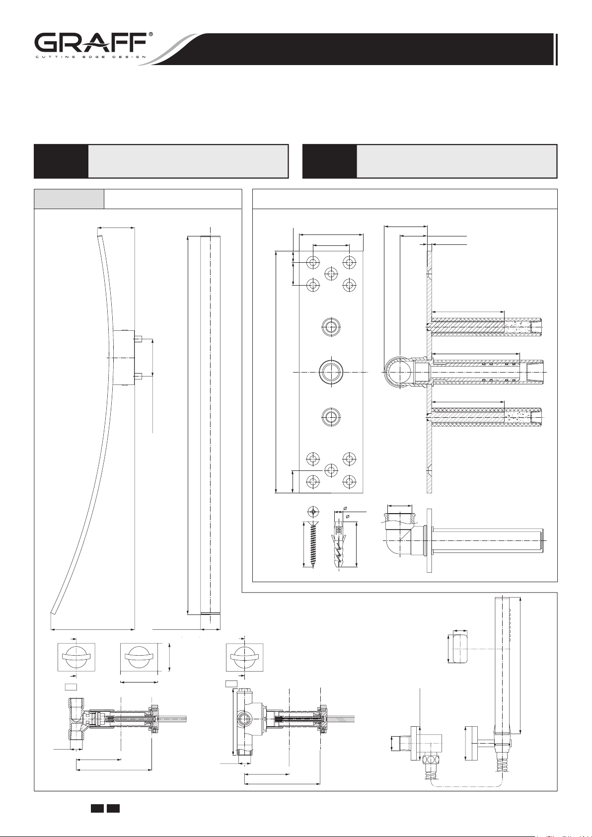
LUNA
Bath Mixer • El Grifo del Baño
~3-29/32" (~ 99mm)
~3-29/32" (~ 99mm)
~39-9/16" (~ 1005mm)
Spout Connection Rough Set
2-3/4" (70mm)
1-37/64" (40mm)
31/64"
(12.5mm)
63/64"
(25mm)
10-15/32" (266mm)
63/64"
(25mm)
25/64"
( 10mm)
~1-55/64" (~47mm)
Conjunto de Conexión del Caño
•
1-3/16" (30mm)
3/16" (5mm)
3-5/32" (80mm)
3-53/64" (97mm)
3-5/32" (80mm)
G3/4"
1-31/32" (50mm)
~8-25/32" (~ 223mm)
A
A
A-A
G1/2"
MIN. 3-1/32" (77mm)
MAX. 5-1/8" (130mm)
IOG 2330.50 Rev. 1 July 2008
GB E
~2-3/64" (~ 52mm)
2-33/64" (64mm)
1-57/64" (48mm)
B
B
B-B
4-9/16" (116mm)
G1/2"
MIN. 3-1/32" (77mm)
MAX. 5-1/8" (130mm)
1
1-31/32" (50mm)
G 1/2
(20mm)
1-37/64" (40mm)
(48mm x 64mm)
1-57/64" x 2-33/64"
25/32"
(48mm x 64mm)
1-57/64" x 2-33/64"
7-11/16" (195mm)
WALL-MOUNTED BATH MIXER
EL GRIFO DEL BAÑO DE MONTADOS EN LA PARED
Installation Instructions ● Instrucciones de Instalación
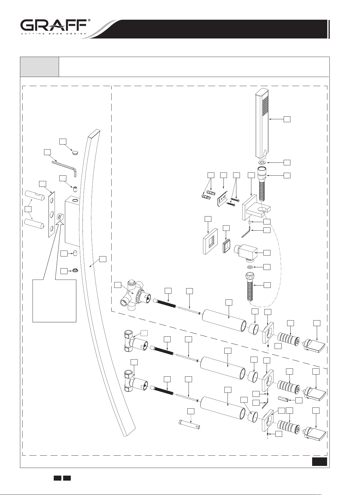
LUNA
2
5
Bath Mixer
•
El Grifo del Baño
Diverter Valve & Shower Handset
4
A
3
•
Válvula de Desviador y de la Regadera de Mano
28
6
8
27
7
17211920
6
9
26
10
8
24
11
18
D
23
7
3
4
Make sure that the
Teflon® insert is in
a proper position
in the spout holder.
Asegúrese que el
insertador de Teflon
se encuentren en
su lugar en el parte
de montaje del caño.
9
16
12A
13
10
22
25
3/4NPT
26
11
13
14
3/4NPT
1
10
14
11
15
7
®
12B
8
13
7
3/4NPT
8
6
12
9
10
12
B
11
13 14
13 14
11
12
C
6
1/4 TURN
1/4 TURN
1/4 DE VUELTA
1/4 DE VUELTA
COUNTERCLOCKWISE OPENING
COUNTERCLOCKWISE OPENING
SE ABRE HACIA LA IZQUIERDA
SE ABRE HACIA LA IZQUIERDA
7 8
1-57/64" (48mm)
1-57/64" (48mm)
1-57/64" (48mm)
1-57/64" (48mm)
2-33/64" (64mm)
2-33/64" (64mm)
OFF OFF
OFF OFF
1/4 TURN
1/4 TURN
1/4 DE VUELTA
COUNTERCLOCKWISE OPENING
SE ABRE HACIA LA IZQUIERDA
1/4 DE VUELTA
CLOCKWISE OPENING
SE ABRE HACIA LA DERECHA
9
10
E
1-57/64" (48mm)
1-57/64" (48mm)
1-57/64" (48mm)
1-57/64" (48mm)
2-33/64" (64mm)
2-33/64" (64mm)
1
IOG 2330.50 Rev. 1 July 2008
GB E
2
WALL-MOUNTED BATH MIXER
EL GRIFO DEL BAÑO DE MONTADOS EN LA PARED
Installation Instructions ● Instrucciones de Instalación
1 WALL-MOUNT SPOUT CAÑO MONTADO EN LA PARED
2 WASHER ARANDELA
3 FIXING SCREW (3 PCS.) TORNILLO DE FIJACIÓN (3 PIEZAS)
4 CAP (3 PCS.) TAPÓN (3 PIEZAS)
5 MOUNTING SLEEVE (3 PCS.) CASQUILLO DE MONTAJE (3 PIEZAS)
VALVE (with counterclockwise opening cartridge)
6
(3 PCS.)
7 STEM EXTENSION (3 PCS.) EXTENSIÓN DE ESPIGA (3 PIEZAS)
8 SCREW (3 PCS.) TORNILLO (3 PIEZAS)
9 PROTECTION SLEEVE (2 PCS.) CASQUILLO DE PROTECCIÓN (2 PIEZAS)
10 PROTECTION CAP (3 PCS.) TAPÓN DE PROTECCIÓN (3 PIEZAS)
11 HANDLE BASE (3 PCS.) BASE DE LA MANILLA (3 PIEZAS)
12 HEX SET SCREW (3 PCS.) TORNILLO DEL BOQUENO (3 PIEZAS)
13 SLEEVE (3 PCS.) CASQUILLO (3 PIEZAS)
14 HANDLE ASSEMBLY (3 PCS.) JUEGO DE MANILLA (3 PIEZAS)
15 DIVERTER VALVE VÁLVULA DE DESVIADOR
16 PROTECTION SLEEVE CASQUILLO DE PROTECCIÓN
17
WALL BRACKET AGARRADOR DE PUNTO
18
SET SCREW TORNILLO DE FIJACIÓN
19
MOUNTING PLATE AZULEJO DE MONTAJE
20
ANCHOR (3 PCS.) TAQUETE (3 PIEZAS)
21
MOUNTING SCREWS (3 PCS.) TORNILLO DE MONTAJE (3 PIEZAS)
22
SUPPLY ELBOW CODO ABASTECEDOR
23
ESCUTCHEON CHAPETÓN
24
RUBBER INSERT INSERTO DE GOMA
25
FLAT SEAL JUNTA PLANO
26
SHOWER HOSE MANGUERA DE LA DUCHA
27
FLAT SEAL JUNTA PLANO
HANDSHOWER with FLOW REGULATING
28
CHECK VALVE
A HEX KEY 13/64” (5mm) LLAVE ALLEN 13/64” (5mm)
B HEX KEY 7/64” (2,5mm) LLAVE ALLEN 7/64” (2,5mm)
C SPECIAL HEX KEY 36/14” (14mm) LLAVE ALLEN ESPECIAL 36/14” (14mm)
D HEX KEY 5/64” (2mm) LLAVE ALLEN 5/64” (2mm)
E SPECIAL KEY (for cartridges) LLAVE ESPECIAL (para los cartuchos)
VÁLVULA (con cartucho que se abre hacia la izquierda)
(3 PIEZAS)
REGADERA DE MANO con VÁLVULA
DE RETENCIÓN Y LIMITACIÓN
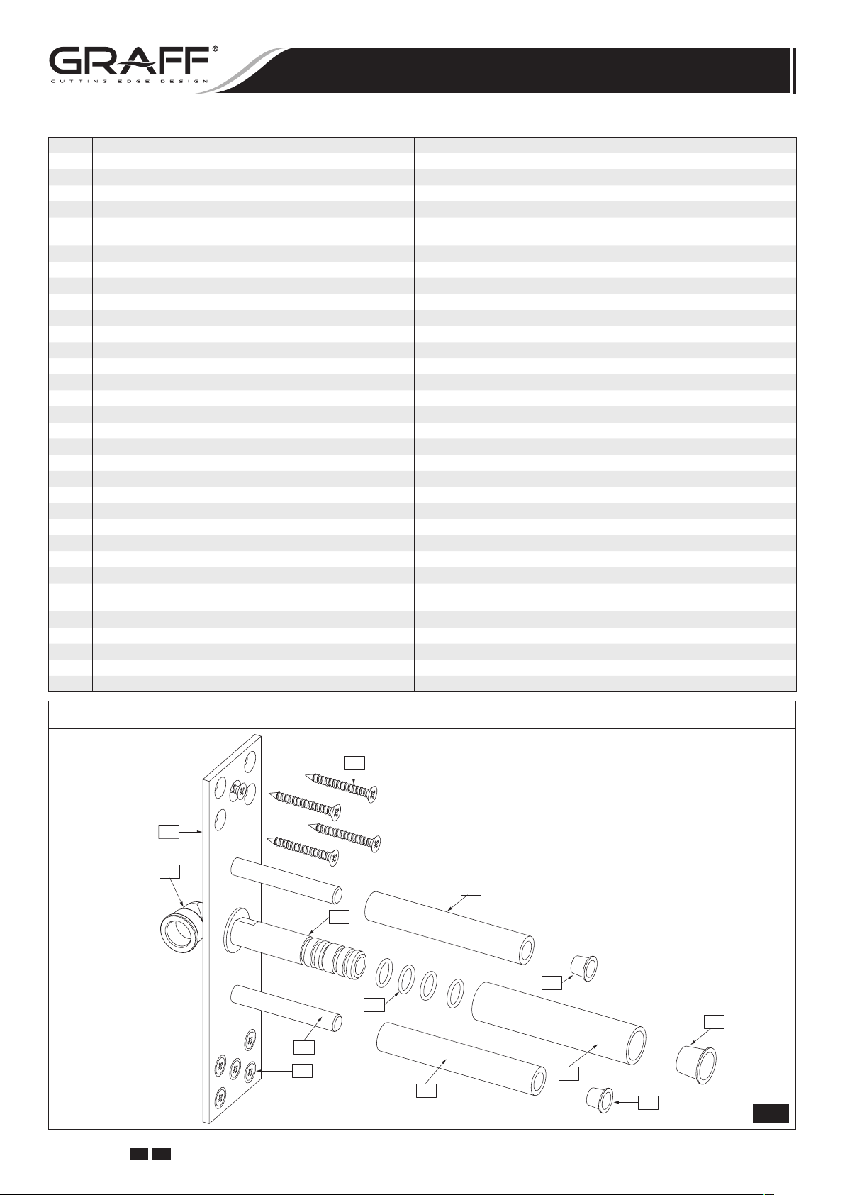
Spout Connection Rough Set • Conjunto de Conexión del Caño
R9
R
R1
R7
R2
R8
R4
R3
R9
R7
R5
R6
R8
2
IOG 2330.50 Rev. 1 July 2008
GB E
3
WALL-MOUNTED BATH MIXER
EL GRIFO DEL BAÑO DE MONTADOS EN LA PARED
Installation Instructions ● Instrucciones de Instalación
R COMPLETE SPOUT CONNECTION ROUGH CONJUNTO COMPLETO DE CONEXIÓN DEL CAÑO
R1 SUPPLY ELBOW G3/4” CODO G3/4” DE SUMINISTRO
R2 SPOUT CONNECTION CONEXIÓN DEL CAÑO
R3 MOUNTING PIN (2 PCS.) PERNO DE MONTAJE (2 PIEZAS)
R4 O-RING SEAL (4 PCS.) JUNTA O-RING (4 PIEZAS)
R5 SPOUT CONNECTION PROTECTION CONECTOR DEL CAÑO DE PROTECCIÓN
R6 PROTECTION CAP TAPÓN DE PROTECCIÓN
R7 PROTECTION SLEEVE (2 PCS.) CASQUILLO DE PROTECCIÓN (2 PIEZAS)
R8 PROTECTION CAP (2 PCS.) TAPÓN DE PROTECCIÓN (2 PIEZAS)
R9 SCREW WITH ANCHOR (10 PCS.) TORNILLO CON ESTACA (10 PIEZAS)
ESPAÑOLENGLISH
Tools and Materials
Tape Measure
•
Pencil
•
Drill
•
Blade Screwdriver
•
Philips Screwdriver
•
Hex Wrenches
•
Level
•
Silicone Sealant
•
Carefully unpack and inspect all the components for damage. To protect against damage, return all components
to the carton until ready to install.
NOTE: Make sure the water supply is off before start of installation.
Bath wall-mount spout (1) is to be mounted on the wall. Before starting of spout installation (1) you should plan:
➣ point of assembly of spout connection rough (R); outflow
from a spout should be at the height guaranteeing a com
fortable use of the bath mixer,
➣ the routing of mixed water supply piping to spout
(1); it is recommended to prepare piping with maximum diameter 3/4” with R3/4” male thread connector to connect the spout connection rough
– see fig. 4.1,
➣ type of wall: standard wall (VERSION 1 - see fig. 3.1) or
marble wall (VERSION 2 - see fig. 3.2).
Before beginning the installation works decide on the type of
wall that it will be used:
VERSION 1 /see fig. 3.1/: Total wall thickness (T):
MIN. 1”- MAX. 2” /standard wall/.
VERSION 2 /see fig. 3.2/: Total wall thickness (T):
MIN. 2”- MAX. 3” /marble wall/.
Position of spout connection rough (R) should be determined
in such way that the
range applicable for each version.
(T) value would be in the MIN.-MAX.
(R)
Herramientas y materiales
Cinta para media
•
Lápiz
•
Taladro
•
Destornillador plano
•
Destornillador de punta de cruz o Phillips
•
Llave hexagonales
•
Nivel
•
Sellador de silicona
•
PRODUCT INSPECTION
Desembale con cuidado y cerciórese de que ningún com
ponente esté dañado. Para protección contra daños, vuelva
a colocar todos los componentes en la caja de embalaje hasta
el momento de su instalación.
SPOUT INSTALLATION
NB: Antes de empezar el montaje asegúrese que el suminis-
tro de agua esté cerrado.
El caño del grifo del baño (1) está destinada para el montaje
en la pared. Antes de iniciar el montaje del caño (1) tiene
que planificar:
-
➣ lugar del montaje del conjunto de conexión del caño
la posición del flujo saliente del caño debe garantizar el
uso cómodo del grifo del baño,
➣ el recurrido de la instalación que lleva el agua mezclada al
caño (1); le recomendamos preparar una instalación de
max diámetro 3⁄4” dotada de una pieza de conexión con la
rosca externa R3⁄4”para unir el conjunto de conexión del
caño (R) - ver el dis. 4.1.
➣ tipo del muro: la pared standard (VARIANTE 1 - ver el
dis. 3.1) o la pared de mármol (VARIANTE 2 - ver el dis.
3.2)
Antes de proceder a la instalación debe determinar el tipo del
muro:
VARIANTE 1 /ver el dis. 3.1/: Espesor total del muro (T):
MIN. 1” – MAX. 2” /la pared estandard/.
VARIANTE 2 /ver el dis. 3.2/: Espesor total del muro (T):
MIN. 2” – MAX. 3” /la pared de mármol/.
Se debe definir la profundidad de colocación del conjunto de
conexión del caño (R) de tal manera que el valor (T) quepa
en los límites MIN.-MAX. para el variante en cuestión.
INSPECCIÓN DEL PRODUCTO
•
ESPAÑOLENGLISH
INSTALACIÓN DEL CAÑO
•
ESPAÑOLENGLISH
-
(R),
IOG 2330.50 Rev. 1 July 2008
GB E
4
WALL-MOUNTED BATH MIXER
EL GRIFO DEL BAÑO DE MONTADOS EN LA PARED
Installation Instructions ● Instrucciones de Instalación
VERSION 1 • VARIANTE 1
Standard Wall: MIN.1”-MAX.2”
Pared Estandard: MIN.1”-MAX.2”
WALL MIN. 1"
WALL MAX. 2"
T T
0.2" (5mm)
CUT
CORTE
CUT
CORTE
CUT
CORTE
VERSION 2 • VARIANTE 2
Marble Wall: MIN.2”-MAX.3”
Pared Marmol: MIN.2”-MAX.3”
WALL MIN. 2"
WALL MAX. 3"
0.2" (5mm)
CUT
CORTE
DON`T CUT
NO CORTE
CUT
CORTE
3.1 3.2
1. Connect the spout connection rough (R) to mounting cavity in the wall using mounting screws
Note: Position spout connection rough (R) correctly in
vertical and horizontal axis using level.
2. Connect water supply piping to supply elbow with a female
thread G3/4” (R1) - see fig. 4.1.
3. Make sure, that all protection sleeves (R5 & R7) are in
correct position on spout connection rough
with construction work on finished wall layer.
4. After finishing the construction work, remove the protec
tion sleeves (R5 & R7) together with protection caps
& R8) from spout rough
the type of wall, that you have, choose the appropriate
version of further steps:
VERSION 1 /see fig. 3.1/: Total wall thickness
MIN. 1”- MAX. 2” /standard wall/
➣ cut the mounting pins
two pins protrude from the finished wall by about 0.2”
(5mm); remove all burrs after cutting,
➣ cut spout connection
nufacturing groove is; remove all burrs after cutting, do
not damage o-ring seals (R4).
(R) – see fig. 4.1. Depending on
(R3) using hack-saw so that the
(R2) at the place where the ma-
(R9).
(R). Continue
(R6
(T):
SPOUT INSTALLATION
1. Sujete el conjunto de conexión del caño
nillos de fijación
Atención: Posicione bien vertical y horizontalmente el
conjunto de conexión del caño
burbuja.
2. Conecte al codo de suministro con rosca externa G3⁄4”
(R1) la instalación que lleva el agua al caño – ver el dis.
4.1.
3. Asegúrese que todos los casquillos de protección (R5 &
-
R7) se encuentren en su lugar en el cojunto de conexión
(R). Ahora puede proceder a realizar la superficie de aca-
bado de la pared.
4. Cuando termine las obras de acabado, quite los casquillos
de protección (R5 & R7) con los tapones de protección
(R6 & R8) del conjunto de conexión (R) - ver el dis. 4.1.
En función del tipo de la pared en su caso escoja el varian
te adecuado para continuar el montaje:
VARIANTE 1 /ver el dis. 3.1/: Espesor total del muro
(T): MIN. 1” – MAX 2” /la pared estandard/
➣ corte los pernos de montaje (R3) con el serrucho para
metal de tal modo que los pernos emerjan de la cara
interior de la pared de acabado de unos 0,2” (5mm);
elimine todas las rebabas que se puedan producir en el
momento de cortar,
➣ corte la conexión del caño
nota la ranura marcada por la fábrica; elimine todas
las rebabas que se puedan producir en el momento de
cortar, no dañe las junta o-ring
(R9) en el vano de montaje en la pared.
INSTALACIÓN DEL CAÑO
•
ESPAÑOLENGLISH
(R) con los tor-
(R) con ayuda del nivel de
(R2) en el lugar donde se
(R4).
-
IOG 2330.50 Rev. 1 July 2008
GB E
5

WALL-MOUNTED BATH MIXER
EL GRIFO DEL BAÑO DE MONTADOS EN LA PARED
Installation Instructions ● Instrucciones de Instalación
4
A
R
R5&R6
Hot Water Inlet
Entrada
de Agua Caliente
R7&R8
R7&R8
5
Finished Wall
R2
Acabado de la pared
3
2
1
5
15
Make sure that the Teflon® insert is
in a proper position in the spout holder.
Asegúrese que el insertador de Teflon
se encuentren en su lugar en el parte
de montaje del caño.
3
®
4
6
9&10
Cold Water Inlet
Entrada
de Agua Fría
16
~1-21/32"(42mm
)
VERSION 2 /see fig. 3.2/: Total wall thickness (T):
MIN. 2”- MAX. 3” /marble wall/
➣
cut the mounting pins (R3) using hack-saw so that the
two pins protrude from the finished wall by about 0.2”
(5mm); remove all burrs after cutting,
➣
ATTENTION! Do not cut spout connection (R2).
5. Screw mounting sleeves
sistance is felt /see fig. 4.3/. ATTENTION! The distance
from the finished wall to the tip of sleeve (5) should
be about 1-21/32” (42mm) /see fig. 4.2/. Top sleeve
(5) should be positioned in such way that the tapered
recess is pointing upwards, and the bottom sleeve
should be positioned in such way that the tapered recess
is pointing downwards /see fig. 4.2/.
6. Put the washer
7. Screw the fixing screws
sockets in spout holder /see fig. 4.3/. Use the hex key
8. Slide the spout
spout connection
is correctly positioned.
9. Holding the spout
screws (3) using the hex key (A).
10. Put in the masking caps
(2) onto the mounting sleeves (5).
(1) over two mounting sleeves (5) and
(R2), pay attention that the washer (2)
(5) onto the pins (R3) until re-
(3) 1-1.5 turns into appropriate
(1) screw all the way in both of fixing
(4) into spout holder.
(5)
(A).
4.2 4.34.1
SPOUT INSTALLATION
VARIANTE 2 /ver el dis. 3.2/: Espesor total del muro (T):
MIN. 2” – MAX. 3” /la pared de mármol/
➣ corte los pernos de montaje (R3) con el serrucho para me-
tal de tal modo que los pernos emerjan de la cara interior
de la pared de acabado de unos 0,2” (5mm); elimine todas
las rebabas que se puedan producir en el momento de cortar,
➣ ATENCIÓN: No corte la conexión del caño (R2).
5. Sobre los pernos de montaje (R3) enrosque los casquillos de
montaje (5) girándolos a tope /ver el dis. 4.3/. ATENCIÓN:
La distancia entre la parte frontal de la pared de acabado y la parte frontal del casquillo (5) debe de ser de
unos 1-21/32” (42 mm) /ver el dis. 4.2/. Ponga el casquillo
superior (5) de tal manera que el recorte cónico esté dirijido
hacia arriba, mientras el casquillo inferior (5) ponga de tal
manera que el recorte esté dirijido hacia abajo /ver el dis.
4.2/.
6. Sobre los casquillos de montaje (5) enroscados ponga la aran-
dela (2)
7. Apriete de un 1-1,5 giro los tornillos de fijación (3) en los
asientos adecuados en la parte de montaje del caño /ver el dis.
4.3/. Use la llave alien (A).
8. Coloque el caño (1) sobre dos casquillos de montaje (5) y la
conexión del caño (R2). Preste atención a posicionar correctamente la arandela (2).
9. Sosteniendo el caño (1) apriete a tope ambos tornillos de fija
ción (3) con la llave alien (A).
.
INSTALACIÓN DEL CAÑO
•
ESPAÑOLENGLISH
-
IOG 2330.50 Rev. 1 July 2008
GB E
6

WALL-MOUNTED BATH MIXER
EL GRIFO DEL BAÑO DE MONTADOS EN LA PARED
Installation Instructions ● Instrucciones de Instalación
VALVE & HANDLE INSTALLATION
1. Prepare the recess in the wall for the valve pipe work
taking into account the maximum and minimum depth
allowed. Place valve
with cap
for valve in wall measured from center of valve inlet/
outlet to finished wall surface is in the range
(77mm) WALL MIN. – 5-1/8” (130mm) WALL MAX.
(see fig. 5.1 & 5.1.1)
NOTE: Use 1/2” nominal tubing and fittings throughout this
installation. Smaller diameter piping upstream or downstream
of the valve will reduce the performance of the valve.
Check the valve for leakage. Complete the finished wall.
2. After execution of the finished wall remove the protection
sleeve
– see fig. 5.2.
3. Unscrew the screw
from a cartridge stem. Cut the stem extension
marked-up place using hack-saw so that the extension
protrude from the finished wall by about 0.2” (5mm); re
move all burrs after cutting. Measure the length
the cut-off part of stem extension
screw end
(8) using hack-saw (see fig. 5.3 & 5.3.1).
4. Replace the stem extension
screw in the screw (8) – see fig. 5.4.
5. Turn the stem of a cartridge in a valve
tion (in clockwise direction) – see fig. 5.5.
6. Insert handle base
against finished wall. Position handle base
hex set screw
(11). The handle base should be positioned like is shown
on fig. 5.5.
7. Measure from the end of sleeve
(D) as in stem extension (7) and screw (8), then cut
the sleeve
Screw the sleeve
key
located on the wall, tighten the sleeve
5.6.
8. Put the hex key
handle (14) and rotate the ring (S) so that the hole in the
ring is in bottom position facing the hex set screw
the handle base
(B) from the hole and push in the handle assembly (14)
onto stem extension
(14) as on fig. 1 “OFF” position.
9. Block carefully the handle
ing the hex key (included with the mixer) – see fig. 5.8.
A screw pin should enter the hole in the slide ring
case of excessive pressure and difficulties with rotation of
the handle loosen up the set screw (12) by a 1⁄4 turn.
Repeat steps for second valve and handle.
(10) into the wall recess. Recommended depth
(9) together with cap (10) by turning and pulling
(8) the same distance (D) and cut the screw
(12) is located at the bottom of handle base
(13) using hack-saw at the marked-up place.
(C), make sure that the handle base (11) is correctly
(6) with the protection sleeve (9)
3-1/32”
(8), take off the stem extension (7)
(7) at the
(D) of
(7), mark off from the
(7) on the cartridge stem and
(6) to “OFF” posi-
(11) to mounting hole until snug
(11) so that
(13) the same length
(13) into valve (6) using provided hex
(13) – see fig.
(B) into the hole of the slide ring (S) in
(12) in
(11) – see fig. 5.7. Remove the hex key
(7) – see fig. 5.7. Set the handle
(14) with a set screw (12) us-
(S). In
INSTALACIÓN DE LA VÁLVULA Y LA MANILLA
•
ESPAÑOLENGLISH
1. Para el trabajo de la tubería de la válvula prepare la hendidura en la pared, considerando la profundidad máxima y
mínima permitida. Ponga la válvula
de protección
pared. La profundidad recomendada para el cuerpo de la
válvula en la pared medida del centro de la entrada/salida
de la válvula a la superficie del acabado es entre
(77mm) WALL MIN. y 5-1/8” (130mm) WALL MAX.
(ver dis. 5.1 y 5.1.1).
NB: En la instalación se recomienda usar los tubos y accesorios de cobre del tamaño nominal de 1/2”. Un diámetro más
pequeño de los tubos de entrada y salida de la válvula puede
causar la reducción de la eficacia de la válvula.
Averigue si en la válvula no hay fugas. Termine el acabado
de la pared.
2. Al terminar el acabado de la pared quite el casquillo de
protección (9) y el tapón (10) girando y tirandólos - ver
-
dis. 5.2.
3. Destornille el tornillo
(7) del cartucho. Corte la extensión de espiga (7) en el
lugar marcado con un serrucho para metal de tal modo
que la extremidad emerja de la cara interior de la pared de
acabado de unos 0.2” (5mm); elimine todas las rebabas
que se puedan producir en el momento de cortar. Mida la
extremidad cortada
mida la misma distancia
(8) y corte el tornillo (8) en el lugar marcado con un serrucho para metal (ver dis. 5.3 y 5.3.1).
4. Inserte de nuevo la extensión de espiga
y apriete el tornillo (8) - ver dis. 5.4.
5. Ponga la espiga del cartucho en la válvula
“cartucho cerrado” - “OFF” (a la derecha) - ver dis. 5.5.
6. Coloque la base de la manilla
taje hasta que toque la pared de acabado. Coloque la base
de la manilla
(12) se encuentre en la parte baja de la base de la manilla
(11). La base de la manilla (11) debe instalarse tal como
se indica en el dis. 5.5.
7. Partiendo del fin del casquillo
que en caso de la extensión de espiga
luego corte el casquillo
serrucho para metal. Enrosque el casquillo
vula (6) con una llave allen (C) adjuntata prestando aten-
ción a la posición correcta de la base de la manilla
la pared, apriete el casquillo (13) - ver dis. 5.6.
8. Ponga la llave hexagonal en el agujerito del anillo de des
lizamiento (S) en la manilla (14) y gire todo el anillo (S)
hasta el punto donde el agujerito del anillo se encuentre al
frente del tornillo hexagonal
(11) - ver dis. 5.7. Quite la llave hexagonal del agujerito
y ponga el juego de manilla
piga (7) - ver dis. 5.7. Ponga la manilla (14) como en el
dis. 1 en la posición “OFF”.
9. Bloquee con cuidado la manilla
usando la llave hexagonal (que va junto con el grifo) - ver
dis. 5.8. El gorrón del tornillo tiene que entrar en agujerito
del anillo de deslizamiento
una presión demasiado grande que dificulte la rotación de
la manilla, afloje el tornillo
(9) y el tapón (10) en la hendidura de la
(8), quite la extensión de la espiga
(D) de la extensión de la espiga (7),
(D) partiendo del fin del tornillo
(11) de tal modo que el tornillo haxagonal
(13) en el lugar marcado con un
(12) en la base de la manilla
(S) de la manilla. En el caso de
(12) a 1⁄4 de su rotación.
(6) junto al casquillo
(7) en el cartucho
(6) en la posición
(11) en el agujero de mon-
(13) la misma distancia (D)
(7) y tornillo (8),
(13) en la vál-
(14) en la extensión de es-
(14) con el tornillo (12)
3-1/32”
(11) en
-
Repita los pasos descritos para otra válvula y manilla.
IOG 2330.50 Rev. 1 July 2008
GB E
7

6
9 10
7 8
WALL-MOUNTED BATH MIXER
EL GRIFO DEL BAÑO DE MONTADOS EN LA PARED
Installation Instructions ● Instrucciones de Instalación
6
9 10
MIN. 3-1/32" (77mm)
MAX. 5-1/8" (130mm)
6
5.1
MAX. 2-3/32"
7
(MOUNTING HOLE)
MAX. 1-21/32" ( 42mm)
5.1.1
6
11
5.2
FINISHED WALL
ACABADO DE LA PARED
~0.2" (~5mm)
CUT
CORTE
D
D
6
CUT
CORTE
13
5.3
5.3.1
B
8
12
5.4 5.5
CUT
D
CORTE
13
5.6
6
7
S
11
14
12
14
B
B
5.7 5.8
IOG 2330.50 Rev. 1 July 2008
GB E
8

WALL-MOUNTED BATH MIXER
EL GRIFO DEL BAÑO DE MONTADOS EN LA PARED
Installation Instructions ● Instrucciones de Instalación
DIVERTER VALVE & HANDLE INSTALLATION
1. Prepare the recess in the wall for the valve pipe work taking
into account the maximum and minimum depth allowed.
Place diverter valve
with cap
for diverter valve in wall measured from center of valve in
let/outlets to finished wall surface is in the range
(77mm) WALL MIN. – 5-1/8” (130mm) WALL MAX.
(see fig. 6.1 & 6.1.1)
NOTE: Use 1/2” nominal tubing and fittings throughout this
installation. Smaller diameter piping upstream or downstream
of the valve will reduce the performance of the valve.
Check the diverter valve for leakage. Complete the finished
wall.
2. After execution of the finished wall remove the protection
sleeve
– see fig. 6.2.
3. Unscrew the screw
from a cartridge stem. Cut the stem extension
marked-up place using hack-saw so that the extension
protrude from the finished wall by about 0.2” (5mm); re
move all burrs after cutting. Measure the length
the cut-off part of stem extension
screw end
(8) using hack-saw (see fig. 6.3 & 6.3.1).
4. Replace the stem extension
screw in the screw (8) – see fig. 6.4.
5. Turn the stem of a cartridge in a diverter valve
in clockwise direction – see fig. 6.5.
6. Insert handle base
against finished wall. Position handle base
hex set screw
(11). The handle base should be positioned like is shown
on fig. 6.5.
7. Measure from the end of sleeve
(D) as in stem extension (7) and screw (8), then cut
the sleeve
Screw the sleeve
vided hex key
is correctly located on the wall, tighten the sleeve
– see fig. 6.6.
8. Put the hex key
handle (14) and rotate the ring (S) so that the hole in the
ring is in bottom position facing the hex set screw
the handle base
(B) from the hole and push in the handle assembly (14)
onto stem extension
(14) as on fig. 10 in “flow out through the shower handset” position.
9. Block carefully the handle
ing the hex key (included with the mixer) – see fig. 6.8.
A screw pin should enter the hole in the slide ring
case of excessive pressure and difficulties with rotation of
the handle loosen up the set screw (12) by a 1⁄4 turn.
(10) into the wall recess. Recommended depth
(16) together with cap (10) by turning and pulling
(8) the same distance (D) and cut the screw
(13) using hack-saw at the marked-up place.
(15) with the protection sleeve (16)
(8), take off the stem extension (7)
(7) at the
(7), mark off from the
(7) on the cartridge stem and
(15) max.
(11) to mounting hole until snug
(11) so that
(12) is located at the bottom of handle base
(13) the same length
(13) into diverter valve (15) using pro-
(C), make sure that the handle base (11)
(B) into the hole of the slide ring (S) in
(11) – see fig. 6.7. Remove the hex key
(7) – see fig. 6.7. Set the handle
(14) with a set screw (12) us-
INSTALACIÓN DE LA VÁLVULA DE DESVIADOR Y LA MANILLA
•
3-1/32”
(D) of
(13)
(12) in
(S). In
ESPAÑOLENGLISH
1. Para el trabajo de la tubería de la válvula prepare la hendidura en la pared, considerando la profundidad máxima
y mínima permitida. Ponga la válvula de desviador
junto al casquillo de protección
-
-
hendidura de la pared. La profundidad recomendada para
el cuerpo de la válvula de desviador en la pared medida
del centro de la entrada / las salidas de la válvula a la
superficie del acabado es entre 3-1/32” (77mm) WALL
MIN. y 5-1/8” (130mm) WALL MAX. (ver dis. 6.1 y
6.1.1).
NB: En la instalación se recomienda usar los tubos y accesorios de cobre del tamaño nominal de 1/2”. Un diámetro más
pequeño de los tubos de entrada y salida de la válvula puede
causar la reducción de la eficacia de la válvula.
Averigue si en la válvula de desviador no hay fugas. Termine
el acabado de la pared.
2. Al terminar el acabado de la pared quite el casquillo de
protección (16) y el tapón (10) girando y tirandólos - ver
dis. 6.2.
3. Destornille el tornillo
(7) del cartucho. Corte la extensión de espiga (7) en el
lugar marcado con un serrucho para metal de tal modo
que la extremidad emerja de la cara interior de la pared de
acabado de unos 0.2” (5mm); elimine todas las rebabas
que se puedan producir en el momento de cortar. Mida la
extremidad cortada
mida la misma distancia
(8) y corte el tornillo (8) en el lugar marcado con un serrucho para metal (ver dis. 6.3 y 6.3.1).
4. Inserte de nuevo la extensión de espiga
y apriete el tornillo (8) - ver dis. 6.4.
5. Ponga la espiga del cartucho en la válvula de desviador
(15) al máximo hacia la derecha - ver dis. 6.5.
6. Coloque la base de la manilla
taje hasta que toque la pared de acabado. Coloque la base
de la manilla
(12) se encuentre en la parte baja de la base de la manilla
(11). La base de la manilla (11) debe instalarse tal como
se indica en el dis. 6.5.
7. Partiendo del fin del casquillo
que en caso de la extensión de espiga
luego corte el casquillo
serrucho para metal. Enrosque el casquillo
vula de desviador
prestando atención a la posición correcta de la base de la
manilla (11) en la pared, apriete el casquillo (13) - ver
dis. 6.6.
8. Ponga la llave hexagonal en el agujerito del anillo de des
lizamiento (S) en la manilla (14) y gire todo el anillo (S)
hasta el punto donde el agujerito del anillo se encuentre al
frente del tornillo hexagonal
(11) - ver dis. 6.7. Quite la llave hexagonal del agujerito y
ponga el juego de manilla
(7) - ver dis. 6.7. Ponga la manilla (14) como en el dis.
10 en la posición “la salida del agua por el regadera de
mano”.
9. Bloquee con cuidado la manilla
usando la llave hexagonal (que va junto con el grifo) - ver
dis. 6.8. El gorrón del tornillo tiene que entrar en agujerito
del anillo de deslizamiento
una presión demasiado grande que dificulte la rotación de
la manilla, afloje el tornillo
(11) de tal modo que el tornillo haxagonal
(8), quite la extensión de la espiga
(D) de la extensión de la espiga (7),
(15) con una llave allen (C) adjuntata
(16) y el tapón (10) en la
(D) partiendo del fin del tornillo
(7) en el cartucho
(11) en el agujero de mon-
(13) la misma distancia (D)
(7) y tornillo (8),
(13) en el lugar marcado con un
(13) en la vál-
(12) en la base de la manilla
(14) en la extensión de espiga
(14) con el tornillo (12)
(S) de la manilla. En el caso de
(12) a 1⁄4 de su rotación.
(15)
-
IOG 2330.50 Rev. 1 July 2008
GB E
9

15
16
10
7
8
WALL-MOUNTED BATH MIXER
EL GRIFO DEL BAÑO DE MONTADOS EN LA PARED
Installation Instructions ● Instrucciones de Instalación
16
10
MIN. 3-1/32" (77mm)
MAX. 5-1/8" (130mm)
15
MAX. 2-3/32"
7 8
(MOUNTING HOLE)
MAX. 1-21/32" ( 42mm)
6.1.1
15
11
6.26.1
FINISHED WALL
ACABADO DE LA PARED
~0.2" (~5mm)
CUT
CORTE
D
CUT
CORTE
D
6.3
6.3.1
15
13
C
CUT
12
D
CORTE
13
6.4 6.5 6.6
15
7
S
11
14
12
B
14
B
6.7 6.8
IOG 2330.50 Rev. 1 July 2008
GB E
10

WALL-MOUNTED BATH MIXER
EL GRIFO DEL BAÑO DE MONTADOS EN LA PARED
Installation Instructions ● Instrucciones de Instalación
WALL BRACKET INSTALLATION
See fig. 7.
Select location.
on family’s needs.
NOTE: Locate so there will be slack in the hose when handshower is in extreme up or down position.
Disassemble the wall bracket as show on fig. 1; lossen the
•
set screw (18) using the included hex key (D).
Choose the location of the bracket on the wall. Drill two
•
5/16” (8mm) holes and put the anchors (20) into the holes.
Tighten the mounting plate (19) using the mounting screws
•
(21).
Slide over wall bracket on the assembled mounting plate
•
(19). After positioning the wall bracket in the correct position, secure it with the set screw (18) using the hex key
(D).
See fig. 8.
Seat the flat seal (27) firmly into the hose nut (26.1). Ca-
refully align the thread of the tapered end of hose
directly to the handshower (28). Hand tighten – do not use
a wrench or pliers. Then place the handshower (28) into the
wall mount holder.
Select wall position for wall bracket based
CONECTE EL EXTREMO CÓNICO DE LA MANGUERA A LA REGADERA DE MANO
(26.1)
MONTAJE DEL AGARRADOR DE PUNTO
•
ESPAÑOLENGLISH
Ver dis. 7.
Escoja la ubicación. Escoja la posición en la pared para el
agarrador de punto basada en los requisitos necesarios de la
familia.
NOTA: Posicione de tal modo que la manguera quede floja
cuando la regadera de mano esté en posición extrema, hacia
arriba o hacia abajo.
Desmonte el agarrador de punto como en el dis. 1; destor-
•
nille el tornillo sin fin (18) con la llave allen (D) adjunta.
Determine en la pared los sitios para montar el agarrador
•
de punto. Taladre dos agujeros de 5/16” (8mm) y meta los
tacos (20) en los foros.
Apriete el azulejo de montaje (19) con los tornillos de
•
montaje (21).
Ponga el agarrador de punto sobre el azulejo de montaje
•
instalado previamente (19). Después de haber colocado el
agarrador de punto en su posición correcta, asegúrelo con
el tornillo sin fin (18) usando la llave allen (D).
CONNECT TAPERED END OF HOSE TO THE HANDSHOWER
Ver dis. 8.
Coloque la junta plana (27) firmemente dentro de la tuer-
ca de la manguera
del extremo cónico de la manguera (26.1) directamente a la
regadera de mano (28). Apriételos a mano – no use la llave
de tuercas ni el alicates. Luego coloque la regadera de mano
(28) en el sujetador de la montura en la pared.
(26.1). Cuidadosamente alinée la rosca
ESPAÑOLENGLISH
20
19
28
17
21
18
D
27
26.1
26
7 8
IOG 2330.50 Rev. 1 July 2008
GB E
11

1/2"NPT
MAX. 5/8"
(MAX. 16mm)
WALL-MOUNTED BATH MIXER
EL GRIFO DEL BAÑO DE MONTADOS EN LA PARED
Installation Instructions ● Instrucciones de Instalación
SUPPLY ELBOW INSTALLATION
ENGLISH
See fig. 9.
Slide the escutcheon (23) with rubber insert (24) over the
•
supply elbow
supply elbow
sure that supply elbow outlet is in a downward facing position.
Slide the escutcheon
finished wall.
Seat the flat seal (25) firmly into the hose nut (26.2). Attach
•
the shower hose to the threaded supply outlet.
(22). Apply Teflon
(22) and thread into riser elbow (G), making
(23) with rubber insert (24) against the
®
tape to threaded end of
G
23&24
22
25
26.2
26
9
OPERATING INSTRUCTIONS
See fig. 10.
The water flow is opened using the handle. It is opened fully
by turning the handle in counterclockwise direction. The intensity of the water flow is regulated by positions between
0° ÷ 90° angle.
CAUTION: To avoid damage the supply elbow or hose finish during installation, wrap with a cloth or tape and use only a smoothjawed wrench. Do not overtighten connections.
MONTAJE DEL CODO ABASTECEDOR
ESPAÑOL
Ver dis. 9.
Deslice con cuidado el chapetón (23) y el inserto de goma
•
(24) sobre el codo de abastecimiento (22). Aplique cinta
Teflon® a las puntas roscadas de la codo de abastecimiento
(22) y enrósquelo en el codo del tubo (G) asegurándose que
la toma del codo de abastecimiento de agua quede en posición cara hacia abajo. Deslice con cuidado el chapetón
el inserto de goma (24) contra la pared de acabado. vertical
de suministro.
Coloque la junta plana (25) firmemente dentro de la tuerca
•
de la manguera (26.2). Fije la manguera de la regadera a la
toma de agua enroscada.
ADVERTENCIA: Para evitar daños del codo de abastecimiento
o el acabado de la manguera durante la instalación, protejálos
con un trapo o una cinta y use solamente la llave de tuercas con
mordaza lisa. No apriete demasiado las conexiones.
DESCRIPCIÓN DEL FUNCIONAMIENTO
•
Ver dis. 10.
Para abrir la salida de ajuste de temperatura use la manilla.
La apertura completa/maxima obtiene girando la manilla a la
izquierda. La regulación de la intensidad del flujo de agua
sucede en las posiciones entre 0° ÷ 90°.
(23) y
ESPAÑOLENGLISH
Turning the handle of diverter valve in counterclockwise direction
causes the water to flow out through the spout. Turning the handle
in clockwise direction causes the water to flow out through the
shower handset.
IOG 2330.50 Rev. 1 July 2008
GB E
Girando la manilla de válvula del desviador a la izquierda causa
la salida del agua por el caño, girando la manilla a la derecha
causa la salida del agua por el regadera de mano.
12

WALL-MOUNTED BATH MIXER
EL GRIFO DEL BAÑO DE MONTADOS EN LA PARED
Installation Instructions ● Instrucciones de Instalación
HOT WATER
AGUA CALIENTE
1/4 TURN
1/4 DE VUELTA
COUNTERCLOCKWISE OPENING
SE ABRE HACIA LA IZQUIERDA
1-57/64" (48mm)
1-57/64" (48mm)
2-33/64" (64mm)
COLD WATER
AGUA FRÍA
1/4 TURN
1/4 DE VUELTA
COUNTERCLOCKWISE OPENING
SE ABRE HACIA LA IZQUIERDA
1-57/64" (48mm)
1-57/64" (48mm)
2-33/64" (64mm)
OFF OFF
ON ON
OPERATING INSTRUCTIONS
The water flow is opened using the handle. It is opened fully
by turning the handle in counterclockwise direction. The intensity of the water flow is regulated by positions between
0° ÷ 90° angle.
DIVERTER VALV
VÁLVULA DE DESVIADOR
1/4 TURN
1/4 DE VUELTA
1-57/64" (48mm)
1-57/64" (48mm)
2-33/64" (64mm)
Flow out through the shower handset
La salida del agua por el regadera de mano
Flow out through the spout
La salida del agua por el caño
DESCRIPCIÓN DEL FUNCIONAMIENTO
•
E
ESPAÑOLENGLISH
Para abrir la salida de ajuste de temperatura use la manilla.
La apertura completa/maxima obtiene girando la manilla a la
izquierda. La regulación de la intensidad del flujo de agua
sucede en las posiciones entre 0° ÷ 90°.
10
Your Graff mixer is designed and engineered in accordance
with the highest quality and performance standards. Be sure
not to damage the finish during installation. Care should be
given to the cleaning of this product. Although its finish is
extremely durable, it can be damaged by harsh abrasives or
polish. Never use abrasive cleaners, acids, solvents, etc. to
clean any
Graff product. To clean, simply wipe gently with
a damp cloth and blot dry with a soft towel.
The guarantee conditions are contained on a separate
sheet.
IN THE EVENT OF A PROBLEM:
e-mail: graff@graff-mixers.com
CARE AND MAINTENANCE
Su grifo de la
Graff esta diseñado y dirigido acuerdo con los
CUIDADO Y MANTENIMIENTO
•
ESPAÑOLENGLISH
estándares de funcionamiento y calidad más altos. Este segu
ro no dañar las terminaciones del grifo durante la instalación.
Cuide el producto manteniendolo siempre limpio. Aunque su
acabado es extremadamente durable, puede ser dañado por
los abrasivos o pulientes ásperos. Nunca utilice limpiadores
abrasivos, ácidos, solventes, el etc. para limpiar cualquier
producto de la Graff. Para limpiar, simplemente use un paño
húmedo y seque con una toalla suave.
GUARANTEE • GARANTÍA
ESPAÑOLENGLISH
Las condiciones de la garantía se encuentran en otra
hoja.
EN CASO DE PROBLEMAS:
e-mail: graff@graff-mixers.com
-
All dimensions and drawings are for reference only. For details, please refer to actual products.
Todas las dimensiones y dibujos sirven únicamente de referencia. Para consultar detalles, ver los productos.
IOG 2330.50 Rev. 1 July 2008
GB E
13

WALL-MOUNTED BATH MIXER
EL GRIFO DEL BAÑO DE MONTADOS EN LA PARED
Installation Instructions ● Instrucciones de Instalación
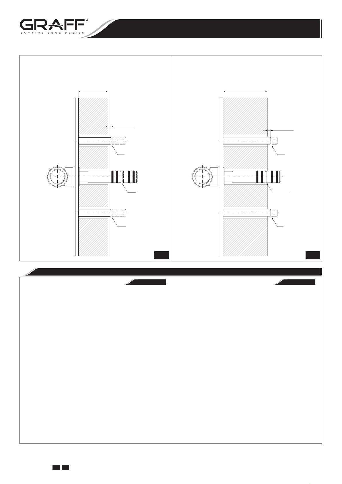
CONFIGURATION FOR BATH MIXER WITHOUT DIVERTER VALVE & SHOWER HANDSET
CONFIGURACIÓN PARA EL GRIFO DEL BAÑO SIN LA VÁLVULA DE DESVIADOR Y DE LA REGADERA DE MANO
Cold Water Inlet
Entrada
Hot Water Inlet
Entrada
de Agua Caliente
de Agua Fría
CONFIGURATION FOR BATH MIXER WITH DIVERTER VALVE & SHOWER HANDSET
CONFIGURACIÓN PARA EL GRIFO DEL BAÑO CON LA VÁLVULA DE DESVIADOR Y DE LA REGADERA DE MANO
Cold Water Inlet
Entrada
Hot Water Inlet
Entrada
de Agua Caliente
IOG 2330.50 Rev. 1 July 2008
GB E
de Agua Fría
14
 Loading...