

Operation, Repair, Parts
™
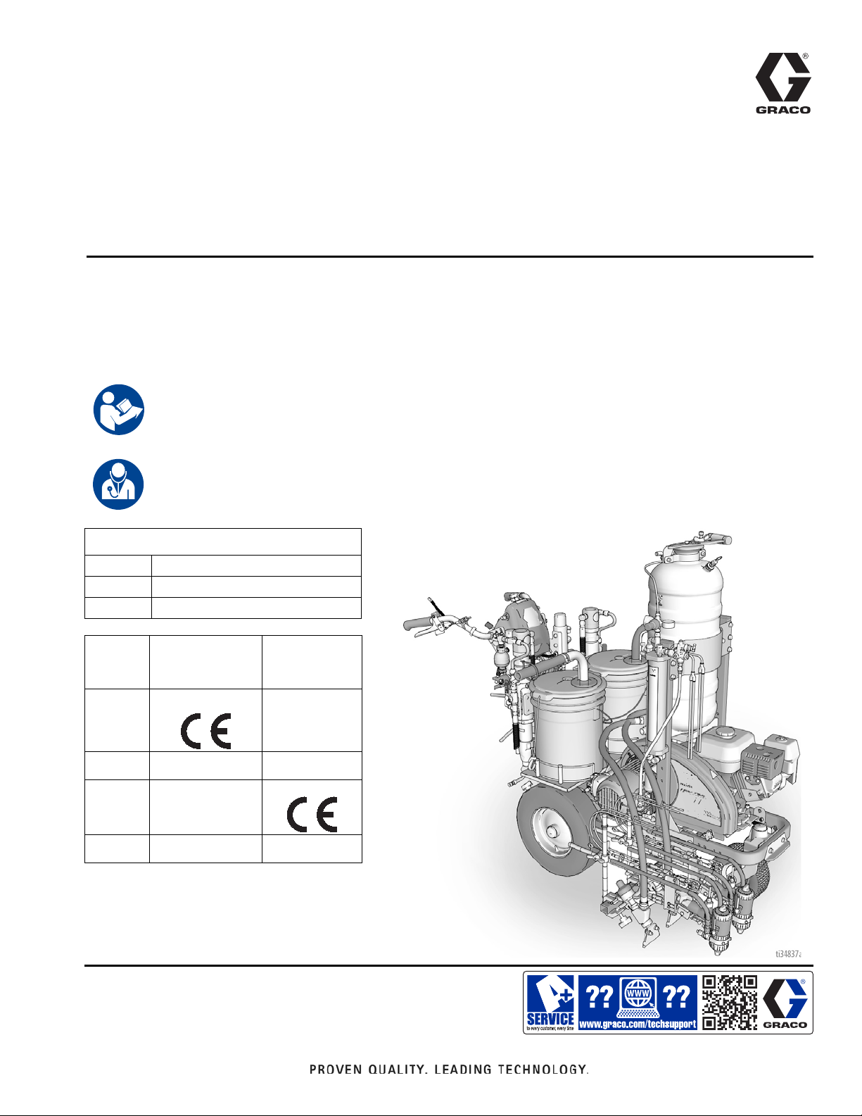
LineLazer
For the application of two component line striping materials.
For professional use only.
For outdoor use only.
Not for use in explosive atmospheres or hazardous locations.
Maximum Operating Pressure: 3300 psi (22.8 MPa, 228 bar)
Important Safety Instructions
Read all warnings and instructions in this manual and in related manuals before using the equipment.
Be familiar with the controls and the proper usage of the equipment.
Save these instructions.
Important Medical Information
Read the medical alert card provided with the gun. It contains injection injury treatment information
for a doctor. Keep it with you when operating the equipment.
V 200MMA 1:1 Airless Line Stripers
3A6466A
EN
Related Manuals:
309277 Pump
3A3428 Auto-Layout Applications Methods
332230 Pressurized Bead System
Model: HP Reflective
1 Auto Gun
1 PBS Tank
17Y234
17Y271
17Y513
17Y512
All auto guns can be actuated manually.
with laser
HP Reflective
2 Auto Guns
1 PBS Tank
with laser
Use only genuine Graco replacement parts.
The use of non-Graco replacement parts may void warranty.

Contents
Contents
Warnings . . . . . . . . . . . . . . . . . . . . . . . . . . . . . . . . . . . . . . . . . 3
Battery Disposal . . . . . . . . . . . . . . . . . . . . . . . . . . . . . . . . 6
Tip Selection . . . . . . . . . . . . . . . . . . . . . . . . . . . . . . . . . . . . . . 7
Component Identification - LLV 200MMA . . . . . . . . . . . . . . . 8
Component Identification - Gun . . . . . . . . . . . . . . . . . . . . . . . 9
Piston Safety Lock . . . . . . . . . . . . . . . . . . . . . . . . . . . . . . . . 10
Loss of Air Pressure . . . . . . . . . . . . . . . . . . . . . . . . . . . . . . . 10
Theory of Operation . . . . . . . . . . . . . . . . . . . . . . . . . . . . . . . 11
Grounding Procedure
(For Flammable Flushing Fluids Only) . . . . . . . . . . . . 12
Pressure Relief Procedure . . . . . . . . . . . . . . . . . . . . . . . . . . 12
Setup/Startup . . . . . . . . . . . . . . . . . . . . . . . . . . . . . . . . . . . . . 13
Keep Components A and B Separate . . . . . . . . . . . . . . . 15
Changing Materials . . . . . . . . . . . . . . . . . . . . . . . . . . . . . 15
Gun Placement . . . . . . . . . . . . . . . . . . . . . . . . . . . . . . . . . . . 18
Install Guns . . . . . . . . . . . . . . . . . . . . . . . . . . . . . . . . . . . 18
Position Gun . . . . . . . . . . . . . . . . . . . . . . . . . . . . . . . . . . 18
Manual Guns Selection . . . . . . . . . . . . . . . . . . . . . . . . . . 18
Auto Guns Selection . . . . . . . . . . . . . . . . . . . . . . . . . . . . 19
Gun Positions Chart . . . . . . . . . . . . . . . . . . . . . . . . . . . . 20
Gun Arm Mounts . . . . . . . . . . . . . . . . . . . . . . . . . . . . . . . 21
Change Gun Position
(Front and Back) . . . . . . . . . . . . . . . . . . . . . . . . . . . 21
Change Gun Position
(Left and Right) . . . . . . . . . . . . . . . . . . . . . . . . . . . . 21
Installation . . . . . . . . . . . . . . . . . . . . . . . . . . . . . . . . . . . . 22
Trigger Sensor Adjustment . . . . . . . . . . . . . . . . . . . . . . . 22
Gun Cable Adjustment . . . . . . . . . . . . . . . . . . . . . . . . . . 23
Straight Line Adjustment . . . . . . . . . . . . . . . . . . . . . . . . . 24
Handle Bar Adjustment . . . . . . . . . . . . . . . . . . . . . . . . . . 24
Dot Laser . . . . . . . . . . . . . . . . . . . . . . . . . . . . . . . . . . . . . 25
Cleanup . . . . . . . . . . . . . . . . . . . . . . . . . . . . . . . . . . . . . . . . . 26
For overnight shutdown . . . . . . . . . . . . . . . . . . . . . . . . . . 28
LineLazer V LiveLook Display . . . . . . . . . . . . . . . . . . . . . . . 29
HP Auto Series . . . . . . . . . . . . . . . . . . . . . . . . . . . . . . . . 29
Initial Setup (HP Auto Series) . . . . . . . . . . . . . . . . . . . . . 30
Striping Mode (HP Auto Series) . . . . . . . . . . . . . . . . . . . 32
Measure Mode (HP Auto Series) . . . . . . . . . . . . . . . . . . . 33
Layout Mode . . . . . . . . . . . . . . . . . . . . . . . . . . . . . . . . . . 34
Stall Calculator . . . . . . . . . . . . . . . . . . . . . . . . . . . . . . . . 35
Angle Calculator . . . . . . . . . . . . . . . . . . . . . . . . . . . . . . . 36
Setup/Information . . . . . . . . . . . . . . . . . . . . . . . . . . . . . . 38
Settings . . . . . . . . . . . . . . . . . . . . . . . . . . . . . . . . . . . . . . 39
Information . . . . . . . . . . . . . . . . . . . . . . . . . . . . . . . . . . . . 40
Data Logging . . . . . . . . . . . . . . . . . . . . . . . . . . . . . . . . . . 42
Maintenance . . . . . . . . . . . . . . . . . . . . . . . . . . . . . . . . . . . . . 43
MMA Fusion Gun . . . . . . . . . . . . . . . . . . . . . . . . . . . . . . . 43
Flush Gun . . . . . . . . . . . . . . . . . . . . . . . . . . . . . . . . . . . . 44
Clean Outside of Gun . . . . . . . . . . . . . . . . . . . . . . . . . . . 44
Tip Guard Adapter . . . . . . . . . . . . . . . . . . . . . . . . . . . . . . 44
Clean Muffler . . . . . . . . . . . . . . . . . . . . . . . . . . . . . . . . . . 44
Clean Fluid Manifold . . . . . . . . . . . . . . . . . . . . . . . . . . . . 44
Clean Mix Chamber Nozzle . . . . . . . . . . . . . . . . . . . . . . . 45
Clean Passages . . . . . . . . . . . . . . . . . . . . . . . . . . . . . . . 45
Remove Tip Adapter . . . . . . . . . . . . . . . . . . . . . . . . . . . . 45
Clean Impingement Ports . . . . . . . . . . . . . . . . . . . . . . . . 46
Lubrication . . . . . . . . . . . . . . . . . . . . . . . . . . . . . . . . . . . . 46
Disassemble Front End of Fusion Gun . . . . . . . . . . . . . . 47
Reassemble Front End of Fusion Gun . . . . . . . . . . . . . . 47
Remove Mix Chamber & Side Seal Cartridges . . . . . . . . 48
Reassemble Mix Chamber & Side Seal Cartridges . . . . . 49
Dissassemble Check Valves . . . . . . . . . . . . . . . . . . . . . . 50
Reassemble Check Valves . . . . . . . . . . . . . . . . . . . . . . . 50
Piston . . . . . . . . . . . . . . . . . . . . . . . . . . . . . . . . . . . . . . . . 51
Piston Safety Lock . . . . . . . . . . . . . . . . . . . . . . . . . . . . . . 52
Air Valve . . . . . . . . . . . . . . . . . . . . . . . . . . . . . . . . . . . . . 52
Maintenance . . . . . . . . . . . . . . . . . . . . . . . . . . . . . . . . . . . . . 53
LineLazer V 200MMA 1:1 . . . . . . . . . . . . . . . . . . . . . . . . 53
Hydraulic Oil/Filter Change . . . . . . . . . . . . . . . . . . . . . . . . . 54
Removal . . . . . . . . . . . . . . . . . . . . . . . . . . . . . . . . . . . . . 54
Installation . . . . . . . . . . . . . . . . . . . . . . . . . . . . . . . . . . . . 54
Troubleshooting . . . . . . . . . . . . . . . . . . . . . . . . . . . . . . . . . . 55
Gun Troubleshooting . . . . . . . . . . . . . . . . . . . . . . . . . . . . . . 60
Gun Repair Kits . . . . . . . . . . . . . . . . . . . . . . . . . . . . . . . . . . . 62
Check Valve Filter Screen Kits . . . . . . . . . . . . . . . . . . . . 62
Drill Bit Kits . . . . . . . . . . . . . . . . . . . . . . . . . . . . . . . . . . . . . . 63
Drill Bit Kit . . . . . . . . . . . . . . . . . . . . . . . . . . . . . . . . . . . . 63
Air Purge Handle Cleanout Drill Kit . . . . . . . . . . . . . . . . . 63
Notes . . . . . . . . . . . . . . . . . . . . . . . . . . . . . . . . . . . . . . . . . . . 64
LineLazer V 200MMA 1:1 . . . . . . . . . . . . . . . . . . . . . . . . . . . 65
Parts Drawing - Frame Assembly . . . . . . . . . . . . . . . . . . . . 66
Parts List - Frame Assembly . . . . . . . . . . . . . . . . . . . . . . . . 67
Parts Drawing - Gun Arm & Gun Trigger . . . . . . . . . . . . . . 68
Parts List . . . . . . . . . . . . . . . . . . . . . . . . . . . . . . . . . . . . . . . . 69
Gun Holder and Arm . . . . . . . . . . . . . . . . . . . . . . . . . . . . 69
Gun Trigger . . . . . . . . . . . . . . . . . . . . . . . . . . . . . . . . . . . 69
Cutaway View - Gun . . . . . . . . . . . . . . . . . . . . . . . . . . . . . . . 70
Parts Drawing - Gun . . . . . . . . . . . . . . . . . . . . . . . . . . . . . . . 71
Parts List - Gun . . . . . . . . . . . . . . . . . . . . . . . . . . . . . . . . . . . 72
Detail Views - Gun . . . . . . . . . . . . . . . . . . . . . . . . . . . . . . . . . 73
Parts Drawing - Handle/Controls . . . . . . . . . . . . . . . . . . . . . 74
Parts List - Handle/Controls . . . . . . . . . . . . . . . . . . . . . . . . . 75
Parts Drawing - Filters A & B . . . . . . . . . . . . . . . . . . . . . . . . 76
Parts List - Filters A & B . . . . . . . . . . . . . . . . . . . . . . . . . . . . 77
Parts Drawing - Fluid Pumps A & B . . . . . . . . . . . . . . . . . . 78
Parts List - Fluid Pumps A & B . . . . . . . . . . . . . . . . . . . . . . 79
Parts Drawing - Engine & Compressor . . . . . . . . . . . . . . . . 80
Parts List - Engine & Compressor . . . . . . . . . . . . . . . . . . . . 81
Parts Drawing - EZ Align Swivel Wheel . . . . . . . . . . . . . . . 82
Parts List - EZ Align Swivel Wheel . . . . . . . . . . . . . . . . . . . 83
Parts Drawing - Pressure Tank . . . . . . . . . . . . . . . . . . . . . . 84
Parts List - Presssure Tank . . . . . . . . . . . . . . . . . . . . . . . . . 85
Accessories - Gun . . . . . . . . . . . . . . . . . . . . . . . . . . . . . . . . 86
Stainless Steel Side Seal Kits . . . . . . . . . . . . . . . . . . . . . 86
Polycarballoy Side Seal Kits . . . . . . . . . . . . . . . . . . . . . . 86
Gun Cover . . . . . . . . . . . . . . . . . . . . . . . . . . . . . . . . . . . . 87
Lubricant for Gun Rebuild . . . . . . . . . . . . . . . . . . . . . . . . 87
Grease Cartridge for Gun Shutdown . . . . . . . . . . . . . . . . 87
Flushing Manifold . . . . . . . . . . . . . . . . . . . . . . . . . . . . . . 87
Solvent Flush Canister Kit . . . . . . . . . . . . . . . . . . . . . . . . 87
Solvent Flush Pail Kit . . . . . . . . . . . . . . . . . . . . . . . . . . . 87
Gun Cleaning Kit . . . . . . . . . . . . . . . . . . . . . . . . . . . . . . . 87
Wiring Diagram . . . . . . . . . . . . . . . . . . . . . . . . . . . . . . . . . . . 88
World Symbol Key . . . . . . . . . . . . . . . . . . . . . . . . . . . . . . . . 89
Technical Specifications . . . . . . . . . . . . . . . . . . . . . . . . . . . 90
CALIFORNIA PROPOSITION 65 . . . . . . . . . . . . . . . . . . 90
Technical Specifications - Gun . . . . . . . . . . . . . . . . . . . . . . 91
End of Product Life . . . . . . . . . . . . . . . . . . . . . . . . . . . . . . . . 91
Graco Standard Warranty . . . . . . . . . . . . . . . . . . . . . . . . . . 92
2 3A6466A Operation, Repair, Parts
Warnings
Warnings
The following warnings are for the setup, use, grounding, maintenance, and repair of this equipment. The exclamation
point symbol alerts you to a general warning and the hazard symbols refer to procedure-specific risks. When these symbols appear in the body of this manual or on warning labels, refer back to these Warnings. Product-specific hazard sym-
bols and warnings not covered in this section may appear throughout the body of this manual where applicable.
FIRE AND EXPLOSION HAZARD
Flammable fumes, such as solvent and paint fumes, in work area can ignite or explode. Paint or solvent flowing through the equipment can cause static sparking. To help prevent fire and explosion:
• Use equipment only in well ventilated area.
• Do not fill fuel tank while engine is running or hot; shut off engine and let it cool. Fuel is flammable and can
ignite or explode if spilled on hot surface.
• Eliminate all ignition sources; such as pilot lights, cigarettes, portable electric lamps, and plastic drop cloths
(potential static arc).
• Ground all equipment in the work area. See Grounding instructions.
• Never spray or flush solvent at high pressure.
• Keep work area free of debris, including solvent, rags and gasoline.
• Do not plug or unplug power cords, or turn power or light switches on or off when flammable fumes are present.
• Use only grounded hoses.
• Hold gun firmly to side of grounded pail when triggering into pail. Do not use pail liners unless they are antistatic or conductive.
• Stop operation immediately if static sparking occurs or you feel a shock. Do not use equipment until you
identify and correct the problem.
• Keep a working fire extinguisher in the work area.
SKIN INJECTION HAZARD
High-pressure spray is able to inject toxins into the body and cause serious bodily injury. In the event that
injection occurs, get immediate surgical treatment.
• Do not aim the gun at, or spray any person or animal.
• Keep hands and other body parts away from the discharge. For example, do not try to stop leaks with any
part of the body.
• Always use the spray tip guard. Do not spray without spray tip guard in place.
• Use Graco spray tips.
• Use caution when cleaning and changing spray tips. In the case where the spray tip clogs while spraying,
follow the Pressure Relief Procedure for turning off the unit and relieving the pressure before removing
the spray tip to clean.
• Equipment maintains pressure after power is shut off. Do not leave the equipment energized or under pressure while unattended. Follow the Pressure Relief Procedure when the equipment is unattended or not
in use, and before servicing, cleaning, or removing parts.
• Check hoses and parts for signs of damage. Replace any damaged hoses or parts.
• This system is capable of producing 3300 psi. Use Graco replacement parts or accessories that are rated
a minimum of 3300 psi.
•
Always engage the piston safety lock when not spraying. Verify the piston safety lock is functioning properly.
• Verify that all connections are secure before operating the unit.
• Know how to stop the unit and bleed pressure quickly. Be thoroughly familiar with the controls.
3A6466A Operation, Repair, Parts 3
Warnings
CARBON MONOXIDE HAZARD
Exhaust contains poisonous carbon monoxide, which is colorless and odorless. Breathing carbon monoxide
can cause death.
• Do not operate in an enclosed area.
EQUIPMENT MISUSE HAZARD
Misuse can cause death or serious injury.
• Do not operate the unit when fatigued or under the influence of drugs or alcohol.
• Do not exceed the maximum working pressure or temperature rating of the lowest rated system component. See Technical Data in all equipment manuals.
• Use fluids and solvents that are compatible with equipment wetted parts. See Technical Data in all equipment manuals. Read fluid and solvent manufacturer’s warnings. For complete information about your material, request Safety Data Sheets (SDSs) from distributor or retailer.
• Do not leave the work area while equipment is energized or under pressure.
• Turn off all equipment and follow the Pressure Relief Procedure when equipment is not in use.
• Check equipment daily. Repair or replace worn or damaged parts immediately with genuine manufacturer’s
replacement parts only.
• Do not alter or modify equipment. Alterations or modifications may void agency approvals and create safety
hazards.
• Make sure all equipment is rated and approved for the environment in which you are using it.
• Use equipment only for its intended purpose. Call your distributor for information.
• Route hoses and cables away from traffic areas, sharp edges, moving parts, and hot surfaces.
• Do not kink or over bend hoses or use hoses to pull equipment.
• Keep children and animals away from work area.
• Comply with all applicable safety regulations.
PRESSURIZED ALUMINUM PARTS HAZARD
Use of fluids that are incompatible with aluminum in pressurized equipment can cause serious chemical reaction and equipment rupture. Failure to follow this warning can result in death, serious injury, or property damage.
• Do not use 1,1,1-trichloroethane, methylene chloride, other halogenated hydrocarbon solvents or fluids
containing such solvents.
• Do not use chlorine bleach.
• Many other fluids may contain chemicals that can react with aluminum. Contact your material supplier for
compatibility.
MOVING PARTS HAZARD
Moving parts can pinch, cut or amputate fingers and other body parts.
• Keep clear of moving parts.
• Do not operate equipment with protective guards or covers removed.
• Equipment can start without warning. Before checking, moving, or servicing equipment, follow the Pres-
sure Relief Procedure and disconnect all power sources.
ENTANGLEMENT HAZARD
Rotating parts can cause serious injury
• Keep clear of moving parts.
• Do not operate equipment with protective guards or covers removed.
• Do not wear loose clothing, jewelry or long hair while operating equipment.
• Equipment can start without warning. Before checking, moving, or servicing equipment, follow the Pres-
sure Relief Procedure and disconnect all power sources.
4 3A6466A Operation, Repair, Parts
Warnings
TOXIC FLUID OR FUMES HAZARD
Toxic fluids or fumes can cause serious injury or death if splashed in the eyes or on skin, inhaled, or swallowed.
• Read Safety Data Sheets (SDSs) to know the specific hazards of the fluids you are using.
• Store hazardous fluid in approved containers, and dispose of it according to applicable guidelines.
BURN HAZARD
Equipment surfaces and fluid that’s heated can become very hot during operation. To avoid severe burns:
• Do not touch hot fluid or equipment.
PERSONAL PROTECTIVE EQUIPMENT
Wear appropriate protective equipment when in the work area to help prevent serious injury, including eye
injury, hearing loss, inhalation of toxic fumes, and burns. This protective equipment includes but is not limited
to:
• Protective eyewear, and hearing protection.
• Respirators, protective clothing, and gloves as recommended by the fluid and solvent manufacturer.
BATTERY HAZARD
The battery may leak, explode, cause burns, or cause an explosion if mishandled. Contents of an open battery can cause severe irritation and/or chemical burns. If on skin, wash with soap and water. If in eyes, flush
with water for at least 15 minutes and get immediate medical attention.
• Only use the battery type specified for use with the equipment. See Technical Data.
• Replace battery only in well-ventilated area and away from flammable or combustible materials, including
paints and solvents.
• Do not dispose of battery in fire or heat above 50°C (122°F). The battery is capable of exploding.
• Do not throw into fire.
• Do not expose battery to water or rain.
• Do not disassemble, crush, or penetrate the battery.
• Do not use or charge a battery that is cracked or damaged.
• Follow local ordinances and/or regulations for disposal.
ELECTRIC SHOCK HAZARD
Hazardous voltage is present in control box while engine is running.
• Turn off engine before servicing equipment.
3A6466A Operation, Repair, Parts 5
Warnings
Important Laser Information for Units with Laser Option
LASER LIGHT HAZARD: AVOID DIRECT EYE CONTACT
Eye exposure to Class IIIa3/3R levels of laser light can potentially present an eye (retinal) injury hazard,
including spot blindness or other retinal injury. To avoid direct eye exposure:
• Never look directly in to a laser beam or point the beam into the eyes of others, even at long distances.
• Never shine the laser at mirror like surfaces which can cause specular reflections of the beam.
• Always set the laser at a height and angle that prevents the beam from shining into people’s eyes.
• Immediately terminate laser emissions if personnel, animals or reflective objects approach the beam.
• Always turn off laser when unattended.
• Do not remove any warning labels from the laser.
• Only properly trained laser operators are to use this product.
• Never allow beams to be aimed toward traffic, vehicles, or heavy equipment. Even when not damaging at
long distances, the high brightness of lasers can distract or disrupt vehicle operations.
• Never point a laser at an aircraft or law enforcement personnel. This is considered a felony in most locations, with the possibility of jail time, heavy fines or both.
• Do not disassemble laser product. Return to factory for all service procedures.
• Laser must be turned OFF when cleaning the lens, so as not to create unwanted laser refraction.
LASER RADIATION HAZARD
Use of controls or adjustments or performance of procedures other than those specified herein may result in
hazardous radiation exposure.
• Do not attempt to open or disassemble the laser housing under any circumstances. Doing so may cause
exposure to potentially hazardous levels of laser radiation.
• No serviceable parts within. Unit is factory sealed.
FIRE AND EXPLOSION HAZARD
Connecting directly to a generator source can create a short or sparking under certain conditions.
• Only connect GL1700 to a dedicated 12 volt DC battery source.
Battery Disposal
Do not place batteries in the trash. Recycle batteries according to local regulations. To find a recycling location in the USA
and Canada call 1-800-822-8837 or go to www.call2recycle.org.
6 3A6466A Operation, Repair, Parts

Tip Selection
ti27606a
ti27606a
in.
(cm)
ti27505a
in.
in.
(cm)
ti27507a
in.
ti27605a
Tip Selection
ti27506a
286321
286323
286325
286327
286331
(cm)
3-4 (7-10)
3-4 (7-10)
3-4 (7-10)
3-4 (7-10)
3-4 (7-10)
(cm)
286423 4-5 (10-13)
286425 4-5 (10-13)
286427 4-5 (10-13)
286429 4-5 (10-13)
286433 4-5 (10-13)
286525 5-6 (13-15)
286527 5-6 (13-15)
286529 5-6 (13-15)
286531 5-6 (13-15)
286533 5-6 (13-15)
286535 5-6 (13-15)
286627 6-8 (15-20)
286629 6-8 (15-20)
286631 6-8 (15-20)
286633 6-8 (15-20)
286635 6-8 (15-20)
286729 8-10 (20-25)
286735 8-10 (20-25)
286831 8-12 (20-30)
286833 8-12 (20-30)
286835 8-12 (20-30)
286935 9-12 (23-30)
ti27508a
ti27509a
ti27510a
Tips smaller than a 0.021 orifice may result in poorly mixed material or frequently clogged tips.
3A6466A Operation, Repair, Parts 7
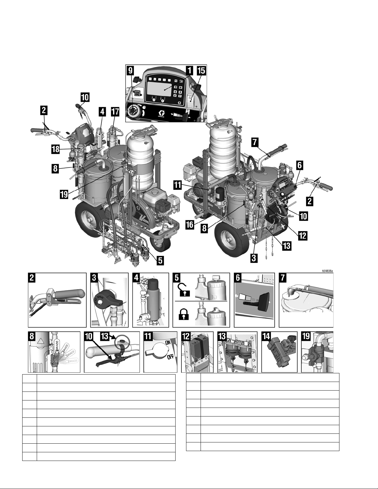
Component Identification - LLV 200MMA
Component Identification - LLV 200MMA
1 Display
2 Spray Gun Control
3 Prime/Spray Valve
4 Filter Manifold
5 Piston Safety Lock
6 Engine/Controls
7 Drain and Siphon Tubes
8 Pump ON/OFF Valve
9 Pressure Control
10 Turn Control
8 3A6466A Operation, Repair, Parts
11 Engine STOP
12 12 Volt Battery
13 Gun Actuator
14 Layout Laser
15 Engine Kill Switch
16 Identification Label
17 A side Fluid Pump
18 B side Fluid Pump
19 Purge Air Valve
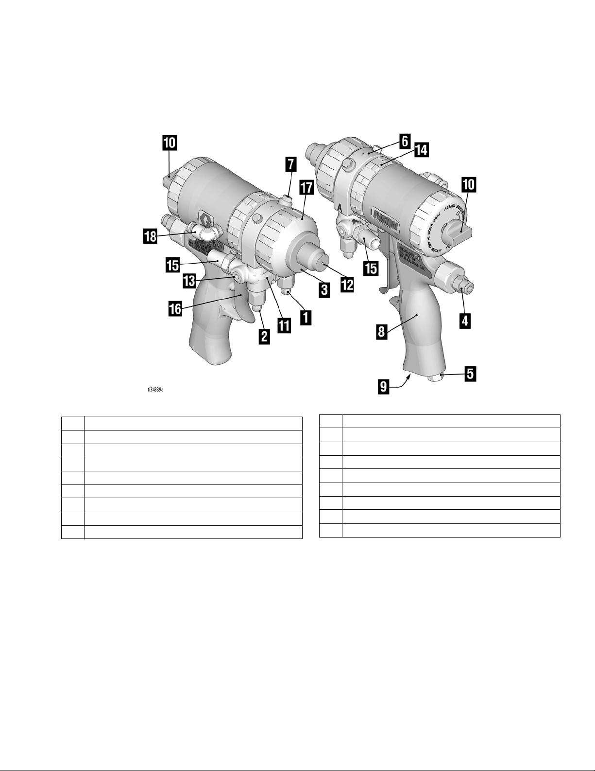
Component Identification - Fusion Gun
Component Identification - Fusion Gun
1 A Side Fluid Valve
2 B Side Fluid Valve
3 Spray Tip Adapter
4 1/4” Air Push-to-Connect for Actuation
5 Muffler
6 Fluid Housing
7 Grease Fitting (under cap)
8 Handle
9 Optional Air Inlet
10 Piston Safety Lock
11 Gun Fluid Manifold
12 Mix Chamber Nozzle
13 Fluid Inlets (optional) (A Side Shown)
14 Lock Ring
15 Fluid Inlet (A Side Shown)
16 Trigger
17 Front Retaining Ring
18 1/4” Air Push to Connect for Purge
3A6466A Operation, Repair, Parts 9
Piston Safety Lock
TI2409A
Engaged
TI2410A
Disengaged
Piston Safety Lock
Engage piston safety lock whenever you are handling
the gun out of the holder and the gun is under pressure,
to avoid accidental triggering.
RISK OF INJECTION
To help prevent serious injury from oressurized fluid,
such as skin injection, splashing fluid and moving
parts, engage the piston safety lock when handling
the gun out of the holder.
To engage piston safety lock: push knob in and turn
clockwise. If engaged, gun will not actuate.
Loss of Air Pressure
In event of loss of air pressure, gun will continue to
spray. To shut off gun, do one of the following:
• Push in Piston Safety Lock, page 10.
• Close fluid valves A and B.
To disengage piston safety lock: push knob in and
turn counterclockwise until it pops out. There will be a
gap between knob and gun body.
10 3A6466A Operation, Repair, Parts
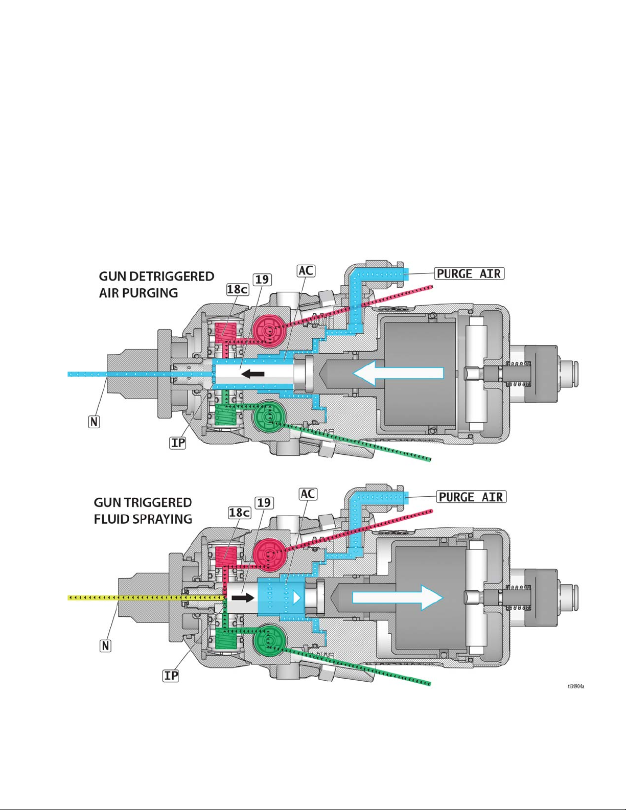
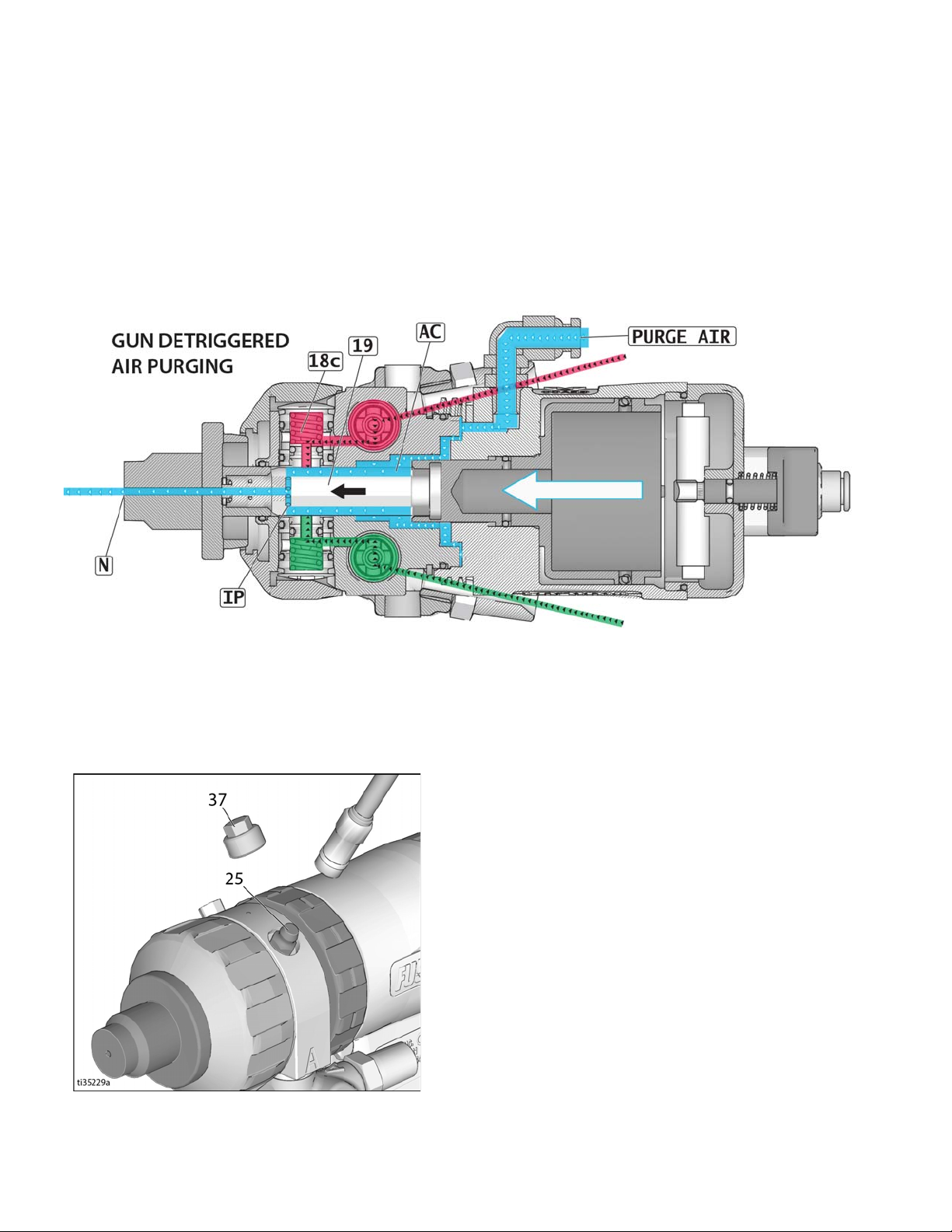
Theory of Gun Operation
Theory of Gun Operation
Gun Triggered (Fluid Spraying)
Mix chamber (19) moves back, shutting off purge air
flow. Impingement ports (IP) align with fluid ports of side
seals (18c), allowing fluid to flow through mix chamber
nozzle (N).
NOTE: Flow paths are not shown to scale, for clarity.
See Parts List, pages 70-72, for part numbers and reference locations.
Gun Detriggered (Air Purging)
Mix chamber (19) moves forward, shutting off fluid flow.
Impingement ports (IP) open to air chamber (AC), allowing purge air to flow through mix chamber nozzle (N).
See page 28 for use of grease fitting.
3A6466A Operation, Repair, Parts 11
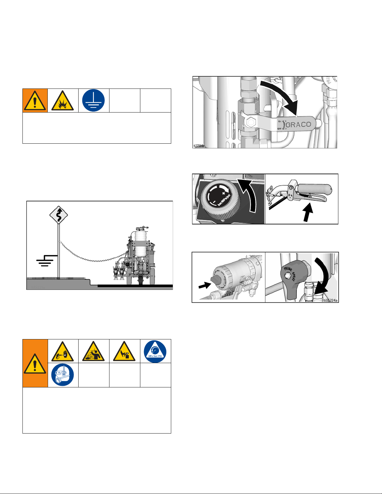
Grounding Procedure (For Flammable Flushing Fluids Only)
ti28013a
Grounding Procedure
(For Flammable Flushing Fluids
Only)
This equipment must be grounded to reduce the risk
of static sparking. Static sparking can cause fumes to
ignite or explode. Grounding provides an escape wire
for the electric current.
1. Position striper so that the tires are not on pavement.
2. Striper is shipped with a grounding clamp. Grounding clamp must attach to grounded object (e.g.
metal sign post).
1. Perform Grounding Procedure (For Flammable
Flushing Fluids Only), page 12.
2. Set both pump ON/OFF valves to OFF.
3. Turn pressure control to lowest setting. Trigger all
guns into waste basket to relieve pressure.
3. Disconnect grounding clamp after flushing is complete.
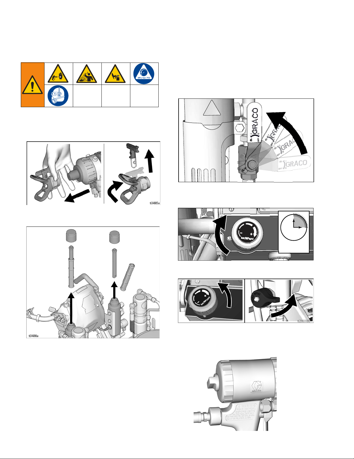
Pressure Relief Procedure
This equipment stays pressurized until pressure is
manually relieved. To help prevent serious injury
from pressurized fluid, such as skin injection, splashing fluid and moving parts, follow the Pressure Relief
Procedure when you stop dispensing and before
cleaning, checking, or servicing the equipment.
4. Engage all gun piston safety locks. Turn prime
valves to prime positions.
5. If you suspect the spray tip or hose is clogged or
that pressure has not been fully relieved:
a. Remove the Spray Tip Adapter (3) and VERY
SLOWLY remove the Front Retaining Ring (17).
b. Loosen the nut or coupling completely.
c. Clear the obstruction in the hose or tip.
12 3A6466A Operation, Repair, Parts
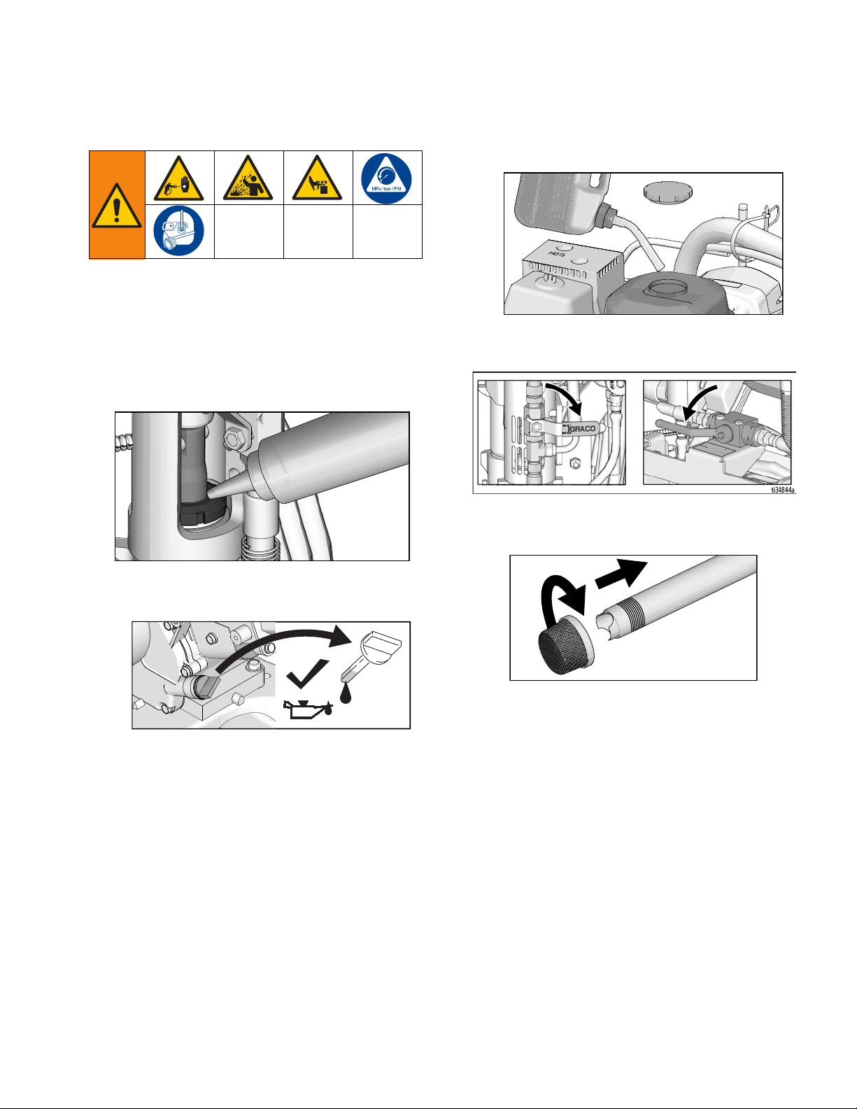
Setup/Startup
ti27611a
ti27612a
Setup/Startup
5. Fill fuel tank.
1. Perform
Pressure Relief Procedure
, page 12.
2. Perform Grounding Procedure (For Flammable
Flushing Fluids Only), page 12, if using flammable
materials.
3. Fill throat packing nut with Throat Seal Liquid (TSL)
to decrease packing wear.
ti28014a
4. Check engine oil level. Add SAE 10W-30 (summer)
or 5W-30 (winter). See engine manual.
6. Set A and B side pump ON/OFF valves to OFF. Set
proportioning valve to “non-proportioning.”
7. If removed, install strainers on both A and B suction
tubes.
ti27610a
3A6466A Operation, Repair, Parts 13
Setup/Startup
ti28015a
ti27617a
ti27618a
ti28151a
ti27620a
ti27766a
ti27618a
ti28152a
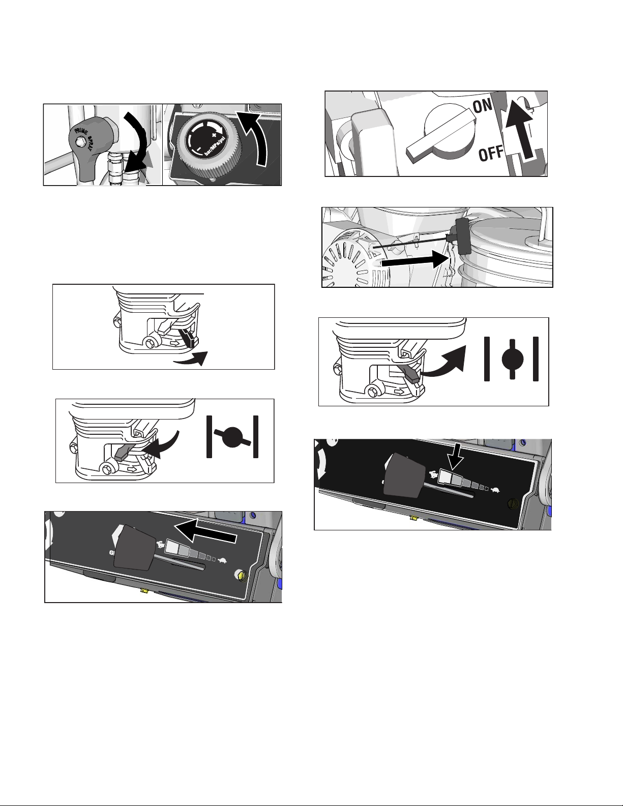
8. Turn both prime valves to prime. Turn pressure control counterclockwise to lowest pressure.
NOTE: Minimum hose size allowable for proper
sprayer operation is 3/8 in. x 11 feet & 1/4 in. x 7 feet
for LLV 200MMA.
9. Start engine:
a. Move fuel valve to open.
ti27616a
d. Set engine switch to ON.
ti27619a
e. Pull starter cord.
10. After engine starts, move choke to open.
b. Move choke to closed.
c. Set throttle to fast.
11. Set throttle to desired setting.
14 3A6466A Operation, Repair, Parts
Setup/Startup
ti28017a
ti28016a
15s
TI2410A
12. Digital display is functional after engine starts.
13. Mix BPO catalyst with component B per manufacturer’s recommendation.
14. Place siphon tube in component B pail and drain
tube in separate waste pail.
15. Set B side pump ON/OFF valve to ON (pump is now
active).
17. Turn pressure down, turn prime valve to spray.
18. Return drain line to component B pail.
19. Engage piston safety lock.
20. Open B side fluid valve (about three full turns).
16. Increase pressure control enough to start pump.
21. Disengage piston safety lock.
Pump is primed when fluid flows from drain tube.
3A6466A Operation, Repair, Parts 15
Setup/Startup
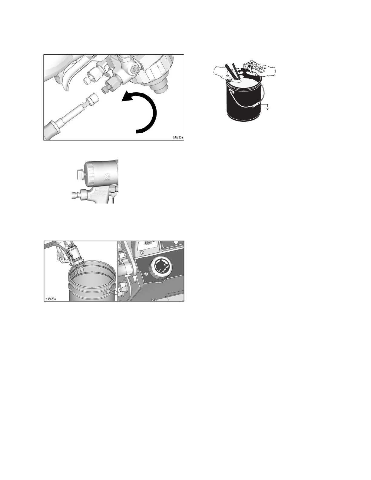
22. Hold gun against a grounded metal flushing pail.
Trigger gun and increase fluid pressure slowly until
pump runs smoothly.
High-pressure spray is able to inject toxins into the
body and cause serious bodily injury. Do not stop
leaks with hand or rag.
23. Inspect fittings for leaks. If leaks occur, turn sprayer
OFF immediately. Perform Pressure Relief Proce-
dure, page 12. Tighten leaky fittings. Repeat
Startup, steps 1 - 22. If no leaks, continue to trigger
gun until system is thoroughly primed. Proceed to
step 24.
27. Insert SwitchTip in tip bore and firmly thread
assembly onto gun.
28. Test spray onto cardboard. Adjust pressure to
achieve desired results.
24. Close B side fluid valve on gun, and repeat step 14 23 for pump “A” with component A material.
25. Perform Pressure Relief Procedure, page 12.
26. Engage piston safety lock. Use end of SwitchTip to
press OneSeal into tip guard, with curve matching
tip bore.
To avoid serious injury from skin injection, do not put
your hand in front of the spray tip when installing or
removing the spray tip and tip guard.
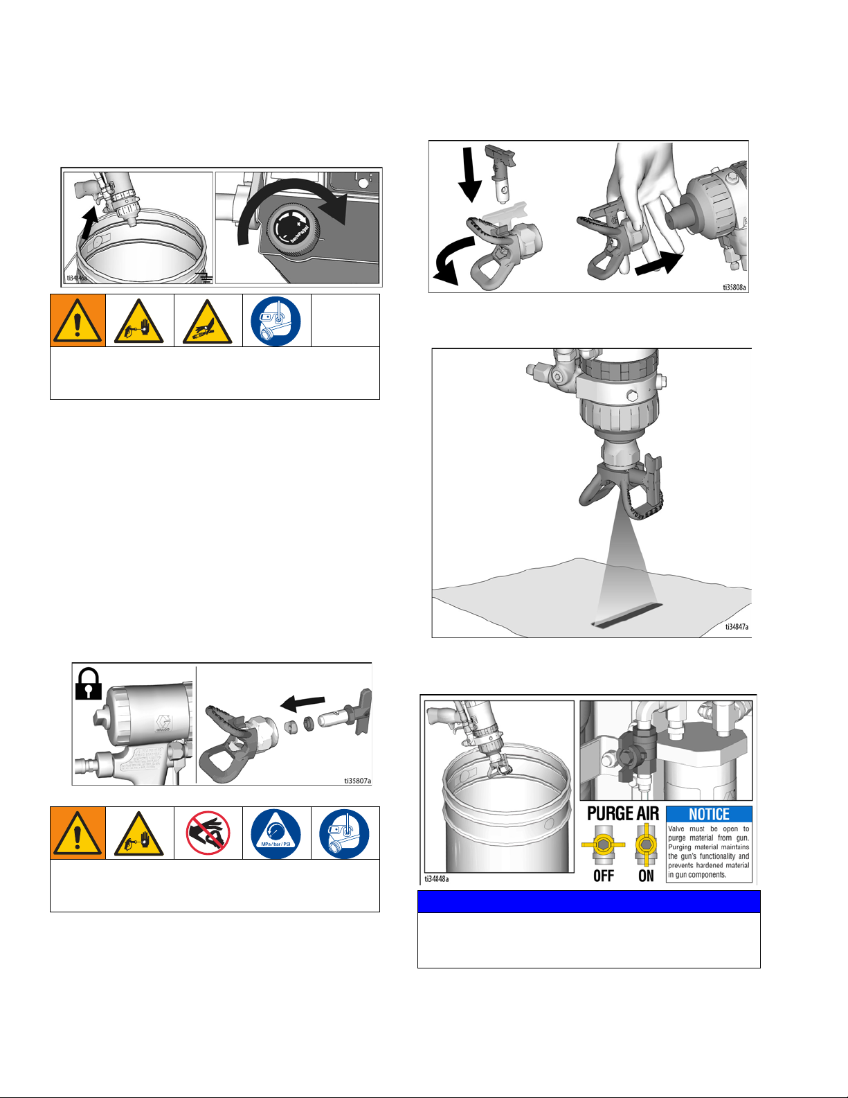
29. Aim gun into waste bucket, open purge air valve to
purge mixed material from tip and spray tip adapter.
NOTICE
Purge air valve must be open to purge material from
gun. Purging material maintains the gun’s functionality
and prevents hardened material in gun components.
16 3A6466A Operation, Repair, Parts
Setup/Startup
Keep Components A and B
Separate
Cross-contamination can result in cured material in
fluid lines which could cause serious injury or damage equipment. To prevent cross-contamination:
• Never interchange component A and component
B wetted parts.
• Never use solvent on one side if it has been contaminated from the other side.
Changing Materials
NOTICE
Changing the material types used in your equipment
requires special attention to avoid equipment damage
and downtime.
• When changing materials, flush the equipment
multiple times to ensure it is thoroughly clean.
• Always clean the fluid inlet strainers on suction
tubes after flushing.
• Check with your material manufacturer for chemical compatibility.
3A6466A Operation, Repair, Parts 17
Gun Placement
ti28129a
1
2
ti27780a
ti27781a
ti27782a
Gun Placement
Install Guns
1. If pressurized, perform Pressure Relief Procedure,
page 12.
2. Insert guns into gun holder. Tighten clamps.
Position Gun
3. Position gun: up/down, forward/reverse, left/right.
See Gun Positions Chart, page 20, for examples.
NOTE: When striping above a curb, the mounting clamp
can be rotated for clearance.
Manual Guns Selection
4. Connect gun cables to left or right gun selector
plates.
a. One gun: Disconnect one gun selector plate
from trigger.
b. Both guns simultaneously: Adjust both gun
selector plates to the same position.
18 3A6466A Operation, Repair, Parts
Auto Guns Selection
1s
ti27784a
ti27881a
ti27785a
Gun
1
Gun
2
Gun
1
Gun
2
Gun
1
Gun
2
Gun
1
Gun
2
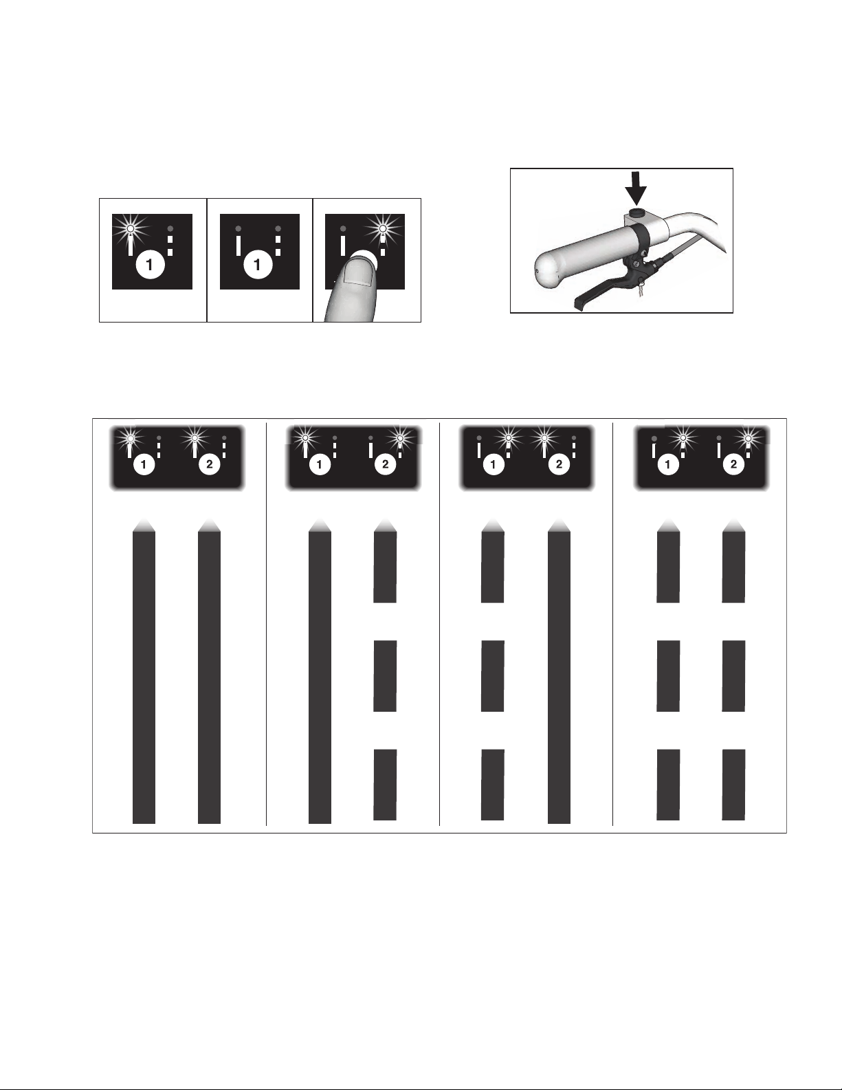
Gun Placement
1. Use the gun selector buttons to determine which
guns are active. Each gun selector has 3 settings:
continuous line, OFF, and programmed line pattern.
2. Use the gun trigger control to actuate guns.
4 Examples:
\
3A6466A Operation, Repair, Parts 19

Gun Placement
Gun Positions Chart
1 One line
2 One line up to 24 in. (61cm) wide
3 Two lines
4 One line or two lines to spray around obstacles
5 One gun curb
6 Two gun curb
7 Two lines or one line up to 24 in. (61 cm) wide
20 3A6466A Operation, Repair, Parts
Gun Placement
ti27797a
ti27800a
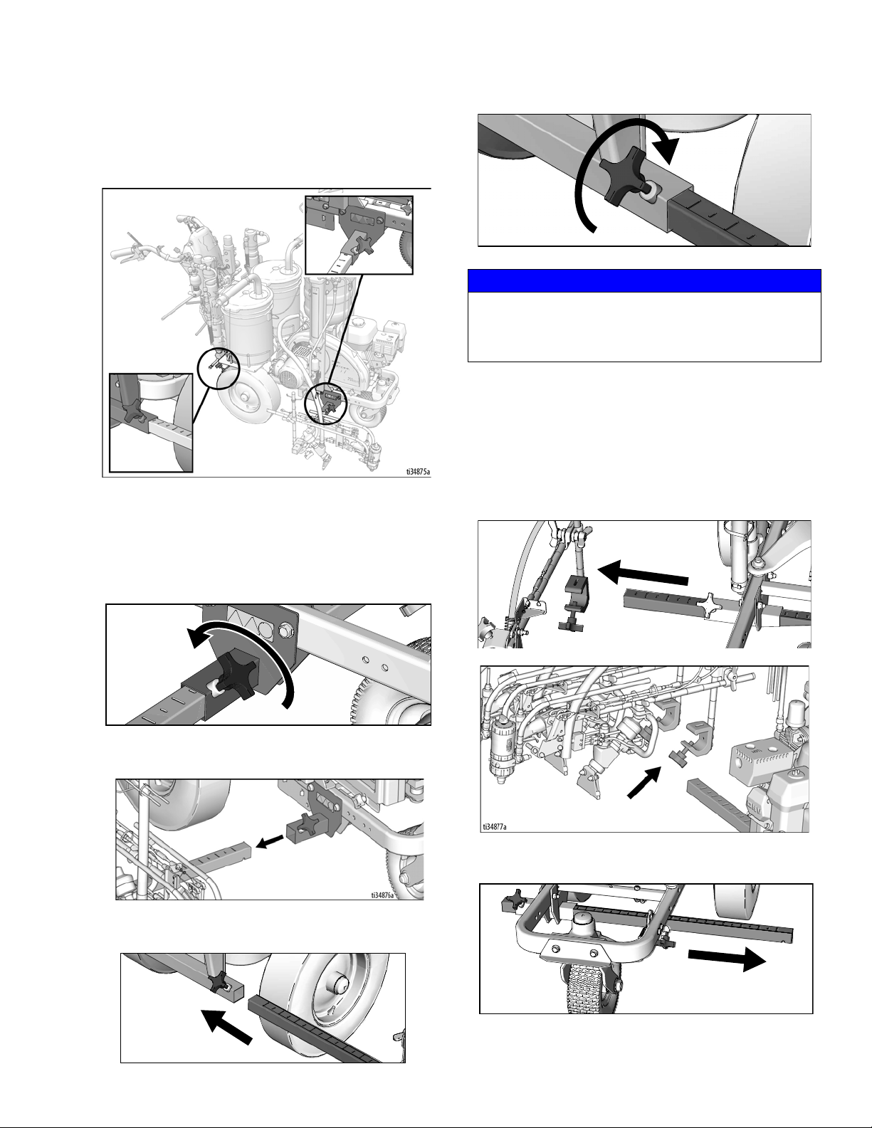
Gun Arm Mounts
This unit is equipped with front and rear gun arm mounts
to allow the operator to place the guns in the optimal
location.
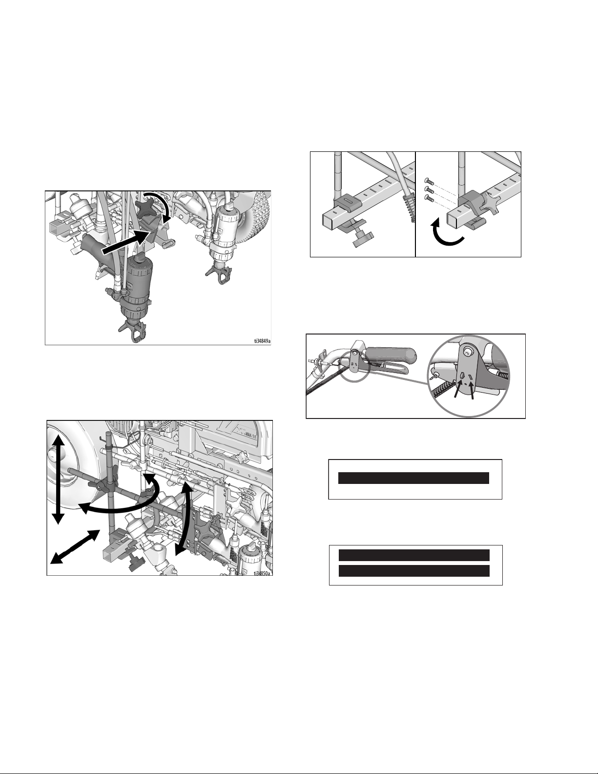
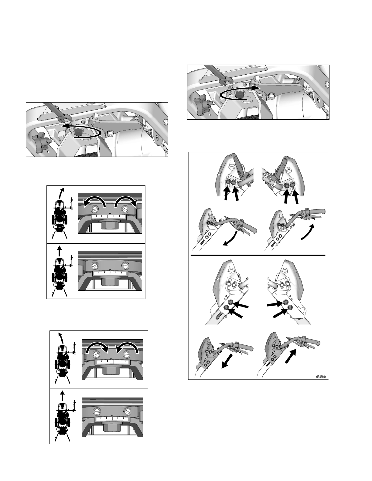
Change Gun Position
4. Tighten gun arm knob into gun arm mounting slot.
ti27798a
NOTICE
Make sure all hoses, cables, and wires are properly
routed through brackets and do NOT rub on tire.
Contact with tire will result in damaged hoses, cables,
and wires.
Change Gun Position
(Left and Right)
Removal
1. Loosen vertical gun arm knob on gun arm mounting
bar and remove.
(Front and Back)
1. Loosen gun arm knob and remove from gun arm
mounting slot.
ti27796a
2. Slide gun arm assembly (including gun and hoses)
out from gun arm mounting slot.
3. Slide gun arm assembly into desired gun arm
mounting slot.
ti27799a
2. Extend mounting bar on opposite side of the
machine.
3A6466A Operation, Repair, Parts 21
Gun Placement
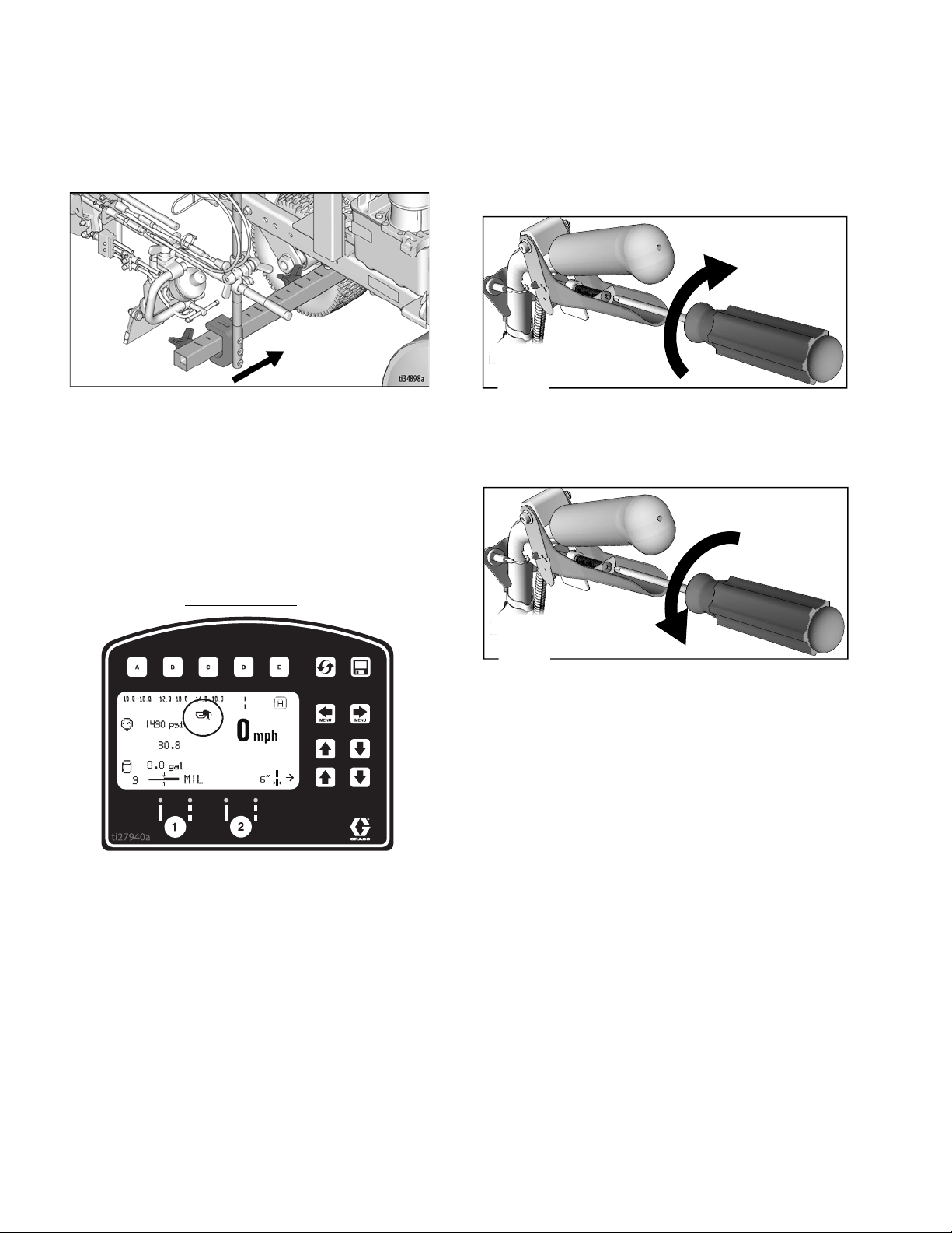
HP Auto Series
Installation
1. Install vertical gun mount onto gun bar.
NOTE: Make sure all hoses, cables, and wires are
properly routed through brackets.
Trigger Sensor Adjustment
1. Start striper engine. Manually pull the trigger. Spray
icon should appear simultaneously with start of fluid
spray.
No fluid spray
2. Turn screw in handle clockwise if spray icon
appears before fluid spray starts.
ti27802a
No spray icon
3. Turn screw in handle counterclockwise if fluid spray
starts before spray icon appears.
ti27803a
4. Continue adjusting screw in handle until timing of
spray icon and fluid spray are synchronized.
22 3A6466A Operation, Repair, Parts
Gun Placement
Manual Guns
Auto Guns
(has 2 locations)
ti27805a
ti27806a
ti27807a
ti27809a
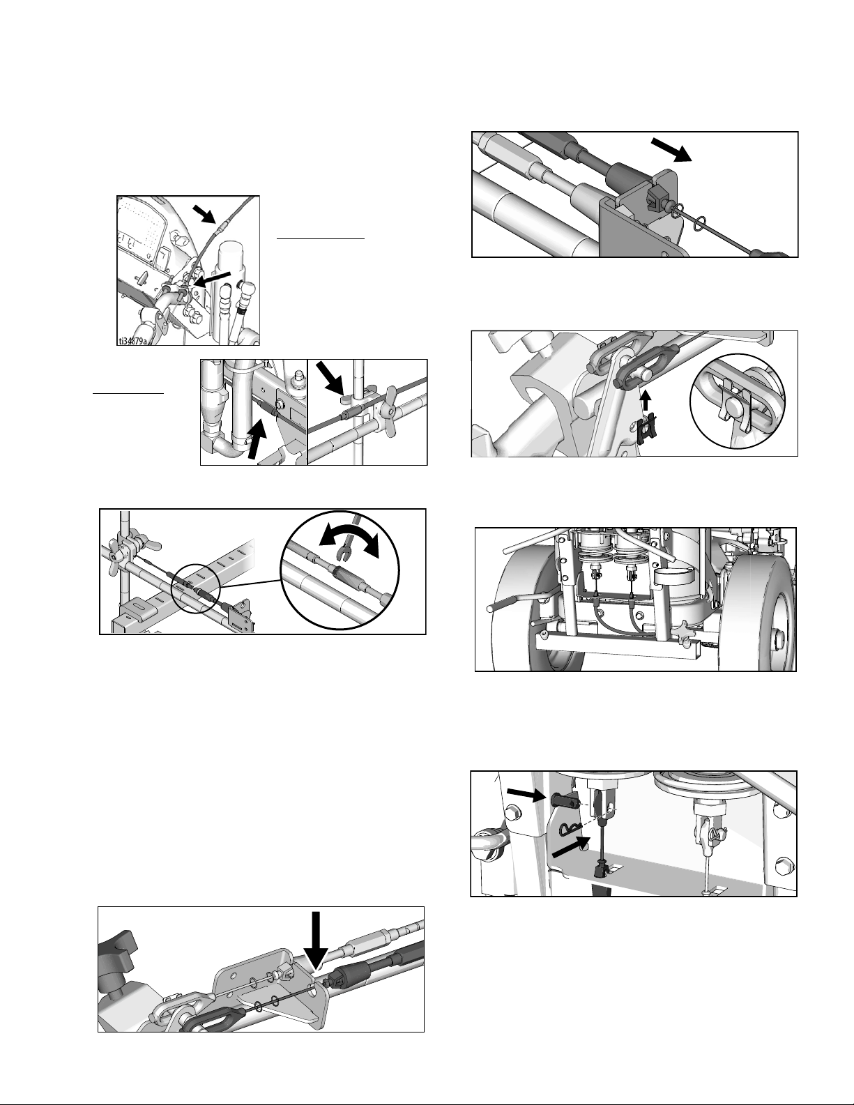
Gun Cable Adjustment
Adjusting the gun cable will increase or decrease the
gap between the trigger plate and the gun trigger. To
adjust trigger gap, perform the steps below.
ti27885a
1. Use wrench to loosen locking nut on cable adjuster.
3. Insert plastic cable retainer into cable bracket hole.
4. Install cable end onto trigger plate pin and install
clip.
5. Route cable around unit and up through cable holes
behind hose mount.
2. Loosen or tighten adjuster until desired result is
3. Use wrench to tighten locking nut on the adjuster.
Adding Gun Cable (Auto Gun)
The HP Auto Series can be equipped with two gun actuators. Each gun actuator is capable of operating one
cable.
1. Select cable end with adjuster.
2. Install exposed cable through cable bracket slot.
3A6466A Operation, Repair, Parts 23
ti27804a
achieved. NOTE: More thread exposed means less
gap between gun trigger and trigger plate.
ti27808a
6. Route cable end loop through rectangular hole in
bracket and insert plastic cable retainer into the
actuator bracket. Install cable end onto actuator rod
and install pin.
Gun Placement
ti27810a
ti27811a
ti27812a
ti27813a
Straight Line Adjustment
The front wheel is set to center the unit and allows the
operator to form straight lines. Over time, the wheel may
become misaligned and will need to be readjusted. To
re-center the front wheel, perform the following steps:
1. Loosen bolt on the front wheel bracket.
2. If striper arcs to the right, loosen left set screw and
tighten right set screw for fine tune adjustment.
4. Roll the striper. Repeat steps 2 and 3 until striper
rolls straight. Tighten bolt on wheel alignment plate
to lock the new wheel setting.
Handle Bar Adjustment
3. If striper arcs to the left, loosen right set screw and
tighten left set screw.
24 3A6466A Operation, Repair, Parts
Gun Placement
ti27886a
ti27888a
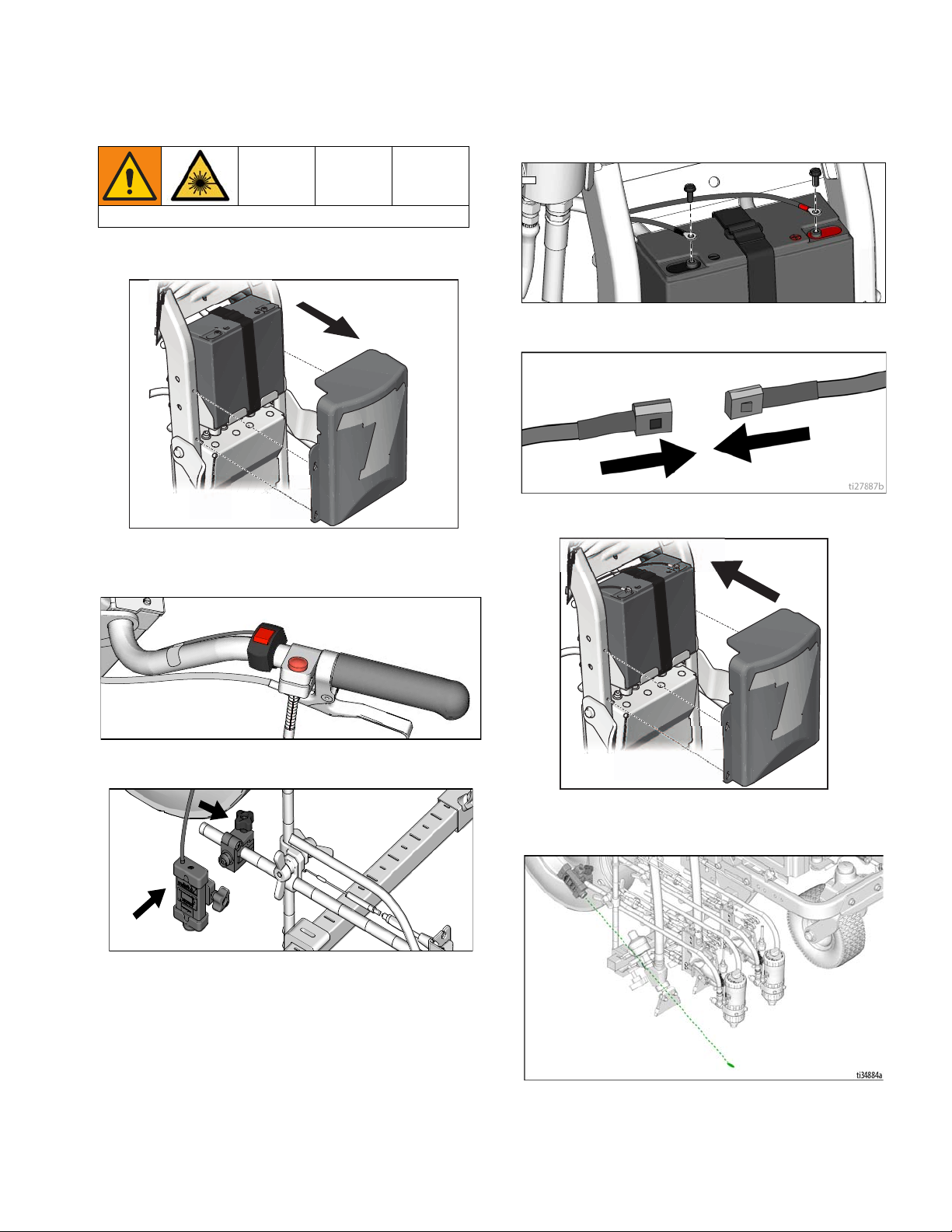
Dot Laser
LASER LIGHT HAZARD. Avoid direct eye contact.
1. Remove battery cover.
2. Attach ON/OFF switch to desired location on the
handle bar.
4. Route wires from the switch to the battery and connect to the (+) and (-) terminals.
ti27818a
5. Connect the switch leads to the wire harness.
6. Reattach battery cover.
ti27815a
3. Attach laser to desired location on the gun arm.
7. Turn on laser and position dot underneath gun
head.
ti27816a
3A6466A Operation, Repair, Parts 25
Cleanup
ti28017a
ti28016a
15s
Cleanup
1. Perform Pressure Relief Procedure, page 12.
2. Remove guard and tip from all guns and place in
acetone.
4. Place B side siphon tube set in grounded metal pail
partially filled with acetone. Attach ground wire to
true earth ground.
5. Set B side pump valve to ON (pump is now active).
3. For both filter manifolds, unscrew cap, remove filter,
and assemble without filter.
6. Increase pressure control enough to start pump.
Pump is primed when solvent flows from drain tube.
7. Turn pressure down, turn prime valve to spray.
8. Return drain line to component B pail.
9. Engage piston safety lock.
26 3A6466A Operation, Repair, Parts
Cleanup
TI2410A
FLUSH
TI3375A
10. Open B fluid valve (about three full turns).
11. Disengage piston safety lock.
12. Hold gun against a grounded metal flushing pail.
Trigger guns and increase fluid pressure slowly until
pump run smoothly.
14. Clean mixing chamber, tip, and tip guard in acetone
fluid.
15. Fill pump with Pump Armor and reassemble filter,
guard and tip.
16. Disassemble Front End of Fusion Gun, page 47.
17. Remove Mix Chamber & Side Seal Cartridges,
page 48, steps 7-8, place in acetone.
18. Lubricate o-rings, see Lubrication, page 46.
19. Dissassemble Check Valves, page 50, step 5,
place in acetone with tips and air cap.
20. Lubricate o-rings, see Lubrication, page 46.
13. Close B fluid valve, turn B pump valve OFF. Repeat
steps 4-12 for A side pump and gun.
21. Reassemble Front End of Fusion Gun, page 47.
22. Reassemble Mix Chamber & Side Seal Car-
tridges, page 49.
23. Reassemble Check Valves, page 50.
24. Each time you spray and store, fill throat packing
nut with TSL to decrease packing wear.
3A6466A Operation, Repair, Parts 27
Cleanup
For overnight shutdown
1. Perform Pressure Relief Procedure, page 12.
2. Leave purge air valve turned on and gun detriggered while machine is still running.
NOTE: Grease gun daily to prevent 2 component curing
and keep fluid passages clean. Purge air carries grease
mist through air chamber (AC), impingement ports (IP),
and out mix chamber nozzle (N), coating all surfaces.
Use Graco 117773 Grease, see page 87.
NOTE: Flow paths are not shown to scale, for clarity.
See Parts List, pages 70-72, for part numbers and reference locations.
3. Remove grease fitting cap (37). Using grease gun,
dispense grease into fitting (25) until grease mist
sprays from mix chamber nozzle (N). Do not
over-grease; use 2 shots maximum. Do not spray
grease mist on sprayed material.
4. Replace grease cap (37).
28 3A6466A Operation, Repair, Parts

LineLazer V LiveLook Display
35
36
HP Auto Series
LineLazer V LiveLook Display
3A6466A Operation, Repair, Parts 29

LineLazer V LiveLook Display
ti35233a
CALIBRATION
A
SETTINGS
B
INFORMATION
C
ENG SPA FRE DEU RUS WORLD
D
LAYOUT MODE
E
ti27828a
26 Ft.
8M
ti27829a
Initial Setup (HP Auto Series)
The initial setup prepares the striper for operation based
on a number of user entered parameters. Language
selections and the units of measure selections can be
set before you start or changed later.
Language
From Setup/Information select appropriate language by
pressing until the language is outlined.
US Units
Pressure = psi
Volume = gallons
Distance = feet
Line Thickness = mil
SI Units
Pressure = bar (MPa available)
Volume = liters
Distance = meters
Line thickness = micron (g/m
2
available)
Paint Specific Gravity = Use UP and DOWN arrows
to set specific gravity. Required to determine paint
thickness.
NOTE: All units can be changed individually at any
time.
Calibration
1. Check rear tire pressure 55 ± 5 psi (379 ± 34 kpa)
and fill if necessary.
2. Extend steel tape to distance greater than 26 ft.
(8m).
ENG = English
SPA = Spanish
FRE = French
DEU = German
RUS = Russian
WORLD = Symbols see World Symbol Key, page
89.
NOTE: Language can be changed later.
Units
Press to enter settings and then again to
enter units. Select appropriate units of measure.
30 3A6466A Operation, Repair, Parts

LineLazer V LiveLook Display
ti35233a
CALIBRATION
A
SETTINGS
B
INFORMATION
C
ENG SPA FRE DEU RUS WORLD
D
LAYOUT MODE
E
ti27912a
3. Press to select Setup/Information.
4. Press for Calibration. Set TRAVEL DIST to 25 ft
(7.6m) or longer. Longer distances ensure better
accuracy, depending on conditions.
6. Press and release gun trigger control to start calibration.
7. Move striper forward. Keep laser dot on steel tape.
8. Stop when laser aligns with 26-ft (8m) or distance
entered on steel tape (25-ft / 7.6m distance).
5. Turn on laser and align laser dot with 1 foot
(30.5cm) on steel tape.
9. Press and release gun trigger control to complete
calibration.
ti27912a
• Calibration is not complete when the exclamation
symbol is displayed.
• Calibration is finished when the check mark symbol
is displayed.
10. Calibration is now complete.
Go to Measure Mode (HP Auto Series), page 33, and
verify accuracy by measuring the tape.
3A6466A Operation, Repair, Parts 31

LineLazer V LiveLook Display
ti27881a
Striping Mode (HP Auto Series)
Ref. Description
Select a “Favorite”, press for less than one sec-
ond.
1
Save a “Favorite”, press and hold for more than
three seconds.
2 Cycles between viewing line width or paint and
space value.
Cycles between Manual Mode, Semi-Automatic
Mode, Automatic Mode.
Manual Mode : Press and hold gun trigger
control to stripe.
Semi-Automatic Mode : Press and release
3
gun trigger control to stripe the programmed
length one time when in Skip Mode.
Automatic Mode : Press and release gun
trigger control to start striping. Press and release
button again to stop.
4 Resets trip distance.
5 Job Data Logger, page 42.
6 Scrolls between menu screens.
7 Paint and Space length OR line width adjustment
buttons.
8 Auto guns activation buttons.
9 MIL thickness. While spraying “Instant MIL avg” is
displayed. When stopped total “Job MIL avg” is
displayed.
10 Total gallons (liters) sprayed, Pump A and B
11 Total line length sprayed.
12 Pressure, Pump A and B
Operating in Striping Mode
Striper must be running before activating gun trigger
control.
1. Make sure engine is running.
2. Use gun activation buttons to select guns and line
type.
ti27893a
3. Press gun trigger control to begin spraying.
In Automatic Mode or Semi-Automatic Mode the or
will flash when gun trigger control is pressed to sig-
nal mode is active.
32 3A6466A Operation, Repair, Parts

LineLazer V LiveLook Display
ti27842a
Measure Mode (HP Auto Series)
Measure Mode replaces a tape measure to measure
distances when laying out an area to be striped.
1. Use to select Measure Mode.
2. Press and release gun trigger control. Move striper
forwards or backwards. (Moving backwards is a
negative distance.)
3. Press and release gun trigger control to end measured length. Up to six lengths are viewable.
The most recent measured length is also saved as the
measured distance in the Stall Calculator display. See
Stall Calculator, page 35.
If an auto gun is activated, press and hold gun trigger
control at any time to apply a dot. If trigger is held while
striper is moving, a dot is marked every 12-inches
(30.5cm).
Ref. Description
1 Press to start measurement, Press to stop
measurement.
2 Hold to reset values to zero.
3 Job Data Logger, page 42.
4 Scroll between main menu screens
5 Last measurement taken
6 Press to start measurement, press to stop
measurement
3A6466A Operation, Repair, Parts 33

LineLazer V LiveLook Display
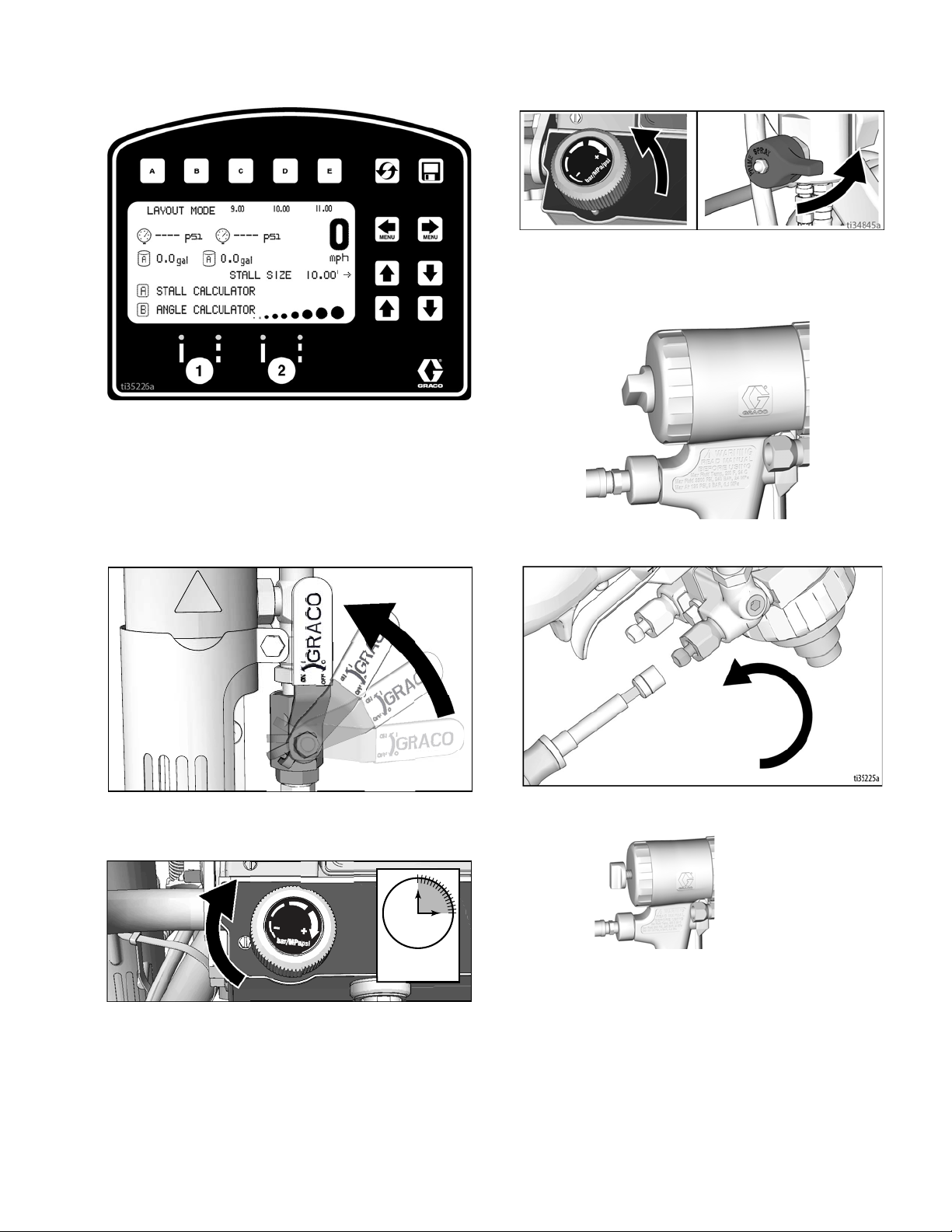
ti27918a
Layout Mode
Layout Mode is used to calculate and mark parking lot
stalls.
1. Use to select Layout Mode.
2. Use gun activation buttons to select guns.
3. Press and release gun trigger control and move
striper forward.
ti27912a
4. Striper default is to place a dot every 9.0 ft (2.7m) to
mark the stall size. Stall size is adjustable.
5. Dots are laid down until gun trigger control is
pressed and released again.
Ref. Description
1 Opens Stall Calculator Menu.
See Stall Calculator, page 35.
2 Opens Angle Calculator Menu.
See Angle Calculator, page 36.
Select a “Favorite”, press for less than one sec-
3
ond.
Save a “Favorite”, press and hold for more than
three seconds.
4 Job Data Logging, page 42.
5 Scroll between menu screens.
6 Adjust stall size/dot spacing.
7 Adjust dot size.
8 Auto Gun activation buttons.
9 Pressure, Pump A and B
10 Total gallons (liters) sprayed, Pump A and B
An indicator on the screen alternately flash when gun
trigger control is pressed to signal mode is active.
34 3A6466A Operation, Repair, Parts

LineLazer V LiveLook Display
Stall Calculator
Stall Calculator is used to set the stall size. The striper
divides the measured length by the stall size to
determine the number of stalls that will fit in the length
measured. User can adjust number of stalls to a round
number and stall width is calculated.
1. Use to select Layout Mode. Press to
open Stall Calculator Menu.
2. The most recent length measured in Measure Mode
is automatically displayed. Press gun trigger control
to start a new measurement. Press again to stop
measuring.
When measuring between curbs, the distance from
the back tire/curb to the gun/laser dot, can be
accounted for by setting the Offset (x) value.
a. Back the striper up to the curb, then use a tape
measure to measure from where the tire touches
the curb to the laser dot on the ground.
b. Use to enter the offset (x) value.
c. This value can be stored by holding for 2
seconds.
d. The value stored under can be added to the
measured distance before or after the
measurement is taken between the curbs.
e. The offset (x) value can also be adjusted before or
after the measurement is taken by using .
Stall size and calculated number of stalls are both
adjustable.
3. Press to return to Layout Mode. The Stall size
is saved and displayed on the Layout Mode screen.
Ref. Description
1 Opens Angle Calculator Menu.
See Angle Calculator, page 36.
2 Exits and returns stall size to Layout Mode.
3 Measured distance.
4 Calculated # of stalls. Changing the number of
stalls will change the stall size.
5 Adjusts number of stalls.
6 Stall size. Changing stall size changes the
calculated # of stalls.
7 Adjusts stall size.
8 Press to start measurement, Press to stop
measurement.
9 Adjust Offset (x)
10 Stores Offset (x). Hold for 2 seconds to store
value.
3A6466A Operation, Repair, Parts 35
4. Press and release gun trigger control to start marking dots. Press and release gun trigger control again
to stop.

LineLazer V LiveLook Display
7
8
5
6
STALL
SIZE
LINE
LENGTH
B
C
STALL
DEPTH
OFF SET
ANGLE
DOT SPACING
ti27857a
Angle Calculator
Angle Calculator is used to determine the offset value
and dot spacing value for a layout.
1. Use to select Layout Mode. Press to
open Angle Calculator Menu.
1
2 3 4
2. Dot spacing (B) and offset (C) are calculated based
on the parameters entered:
Stall angle
Stall depth
Stall size (width)
Line Length
3. Press to transfer calculated offset distance to
Layout Mode. Save this value in favorites if desired.
ti27850a
Ref. Description
1 Transfers calculated dot spacing, B, to Layout
Mode.
2 Transfers calculated offset, C, to Layout Mode.
3 Exits and returns to Layout Mode without transfer-
ring any values.
4 Data Logging.
5 Select input variables.
6 Adjust the variable selected.
7 Calculated dot spacing, B.
8 Calculated offset, C.
36 3A6466A Operation, Repair, Parts

LineLazer V LiveLook Display
ti27842a
4. Press to transfer calculated dot spacing dis-
tance to Layout Mode. Save this value in favorites if
desired.
5. Press and release gun trigger control to start marking stall size dots. Press and release gun trigger
control to stop marking.
3A6466A Operation, Repair, Parts 37

LineLazer V LiveLook Display
Setup/Information
Use to select Setup/Information.
Press to select Language.
See Language, page 30.
See Calibration, page 30.
See Settings, page 39.
See Information, page 40.
See Marker Layout Mode, page 41.
38 3A6466A Operation, Repair, Parts

Settings
Use to select Setup/Information. Press to
open Settings Menu.
Chooses the machine type. Necessary for accurate gallon
counting.
Use to set time and date. Needed for accurate Data Logging.
LineLazer V LiveLook Display
Set units with
Use to adjust screen contrast to the desired value.
For programmed skip lines, press to choose:
Paint first
or
Space first
ti28158a
In Auto-mode, guns won’t fire or will shut off if speed is below set
value.
Enable or Disable Low Speed Shutoff
Adjust low speed setting.
3A6466A Operation, Repair, Parts 39

LineLazer V LiveLook Display
Stroke Counter
Pressure Transducer
Distance Sensor
Touch Pad Buttons
Engine Voltage
Battery Voltage
Clutch
Solenoid 1
Solenoid 2
Battery charge state
Information
Use to select Setup/Information. Press to
open Information Menu.
Displays and logs life, data, and striper information.
View and test functionality of component
Logs last four error codes that occurred.
Code Description
02 = Over pressure
03 = No transducer detected
Reset error codes
40 3A6466A Operation, Repair, Parts
LineLazer V LiveLook Display
1
2
3
4
ti27860a
1
ti27862a
[1] 8.00´
[2] 4.00´
[3] 4.00´
[4] 16.00´
[5] 4.00´
[6] 4.00´
[7] 8.00´
[8] 0.00´
8.00 ft. 8.00 ft.
4.00 ft.
4.00 ft.
16.00 ft.
48.00 ft.
4.00 ft.4.00 ft.
ti23812a
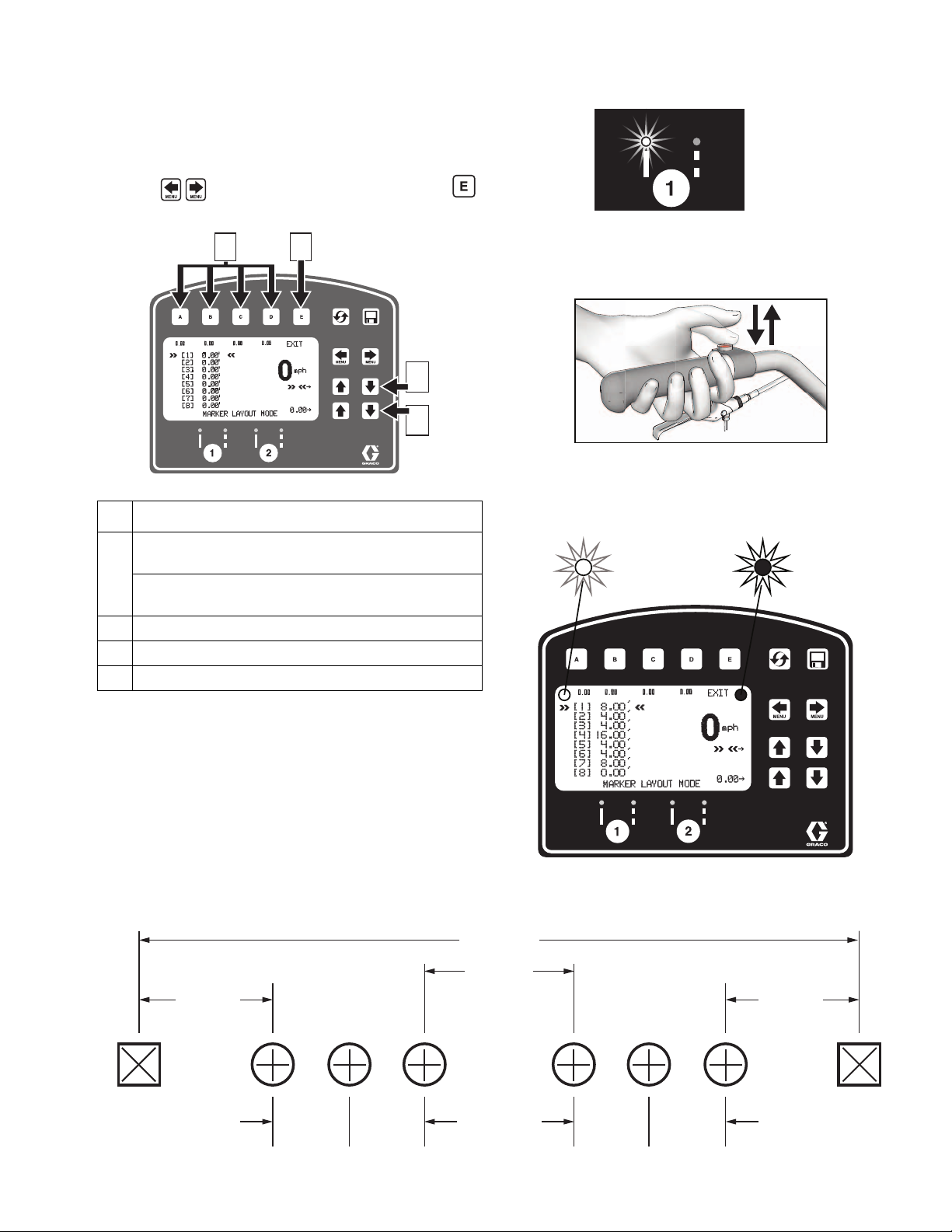
Marker Layout Mode
The Marker Layout Mode feature sprays a dot or a
series of dots to mark an area.
1. Use to select Setup/Information. Press
to open Marker Layout Mode.
Ref. Description
4. Set gun switch to skip line or solid line.
ti27918a
5. Press and release gun trigger control to start marking dots. Press and release gun trigger control again
to stop.
ti27912a
An indicator before and after Marker Mode on the
screen alternately flash when gun trigger control is
pressed to signal mode is active.
Select a “Favorite”, press for less than one second.
1
Save a “Favorite”, press and hold for more than
three seconds.
2 Exits and returns to Information Menu.
3 Select value to change.
4 Adjust spacing value.
2. Use arrow keys to set up a marker pattern.
3. Marker layout example shows a typical lane layout
for reflective markers. Set space sizes up to eight
consecutive measurements. By leaving zeros in any
space, Marker Layout Mode will skip to the next
measurement in a continuous loop.
Some other uses of Marker Layout Mode are:
• Multiple spaced handicap stall layout
• Double line stalls
3A6466A Operation, Repair, Parts 41

LineLazer V LiveLook Display
ti28063a
START RECORDING NEW JOB
VIEW JOBS
EXIT
A
E
Data Logging
The LLV control is equipped with Data Logging, which
allows the user to recall job data and export the data
from the machine to a USB drive.
1. Press the to open the Data Logging pop up
window.
2. Choose to start recording a new job or view jobs
previously done.
Start recording a new job.
Erase all jobs
Export all jobs to USB
Erase jobs
Export job to USB
Job data is compiled while spraying. A summary of volume sprayed, distance sprayed and average mil thickness is displayed for the entire job. The job is also
broken down by colors, line widths and stencil volume
sprayed.
42 3A6466A Operation, Repair, Parts

Maintenance
TI3864a
Reversible
Reversible
Maintenance
MMA Fusion Gun
Supplied Tool Kit
• Hex Nut Driver; 5/16
• Screwdriver; 1/8 blade
• Nozzle Drill Bit; See T
• Impingement Port Drill Bit; various sizes depending
on port size. See T
• 117661 Pin Vise; dual reversible chucks
• 551189 Grease Gun; with 3 oz grease
ABLE 1, page 45.
ABLE 3, page 45.
As Needed
1. Clean Outside of Gun, page 44.
2. Clean Mix Chamber Nozzle, page 45, a minimum
of once a day.
3. Spray Tip Adapter, page 44.
4. Clean Muffler, page 44.
5. Clean Fluid Manifold, page 44.
6. Clean Passages, page 45.
7. Clean Impingement Ports, page 46.
Daily
Follow Cleanup, page 26.
Weekly to Monthly
1. Clean Mix Chamber and Side Seal Cartridges, page
49. Check o-rings.
Keep Gun Clean
Keep gun clean with accessory gun cover, page 87.
Applying a light coat of lubricant will make cleaning easier.
2. Clean/Dissassemble Check Valves, page 50.
Check o-rings and filters.
3A6466A Operation, Repair, Parts 43
Maintenance
Flush Gun
If it is necessary to flush gun, use following procedure.
1. Follow Grounding Procedure (For Flammable
Flushing Fluids Only), page 12.
2. Flush with acetone into a grounded metal pail, holding a metal part of fluid manifold firmly to side of
pail. Use the lowest possible fluid pressure when
flushing.
3. Perform Pressure Relief Procedure, page 12.
Clean Outside of Gun
Clean Muffler
Remove and clean muffler with acetone.
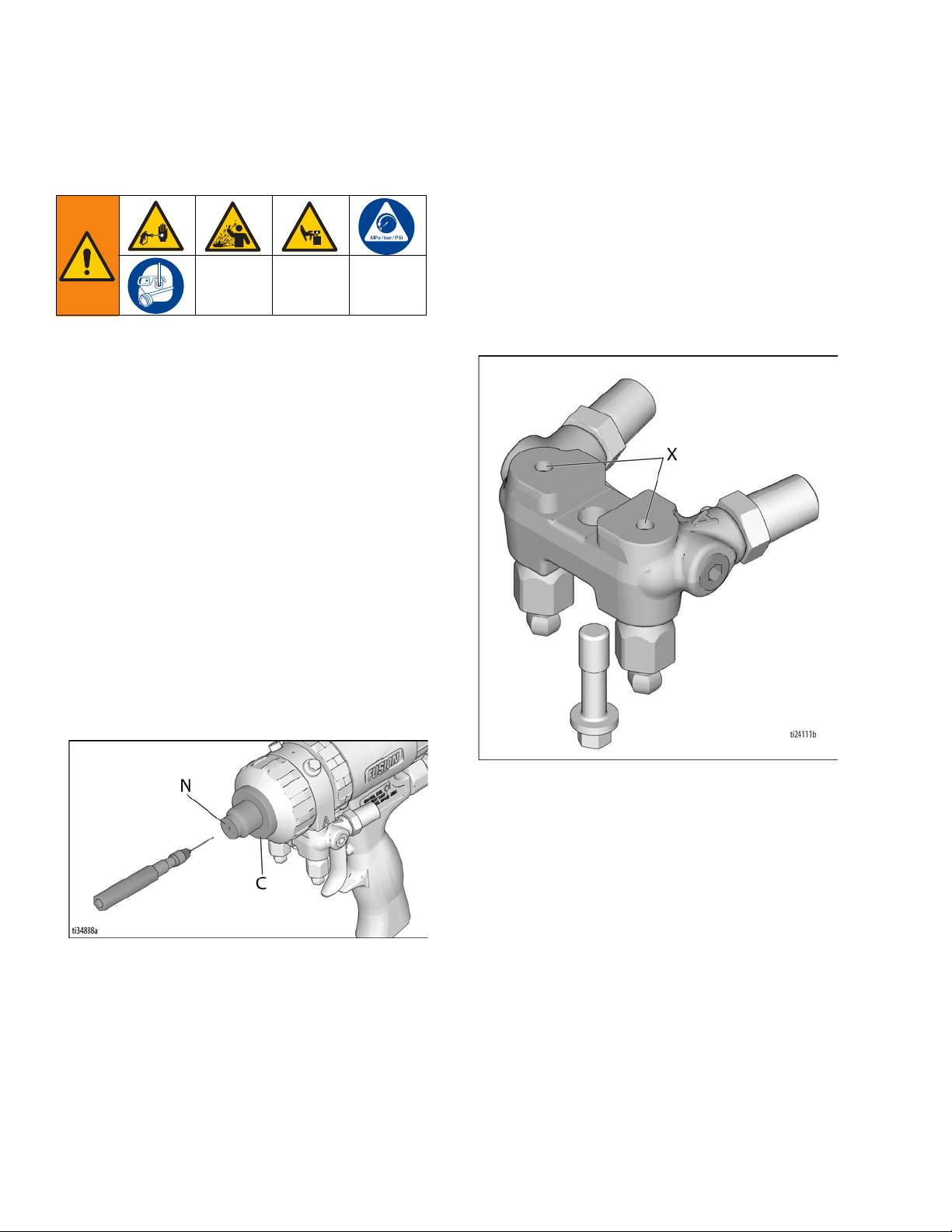
Clean Fluid Manifold
Clean fluid manifold sealing faces with acetone and a
brush whenever removed from gun. Be sure to clean the
two fluid ports (X) in the top mating surface. Do not damage the flat sealing surfaces. Coat with grease if left
exposed, to seal out moisture.
Wipe off outside of gun with acetone.
Spray Tip Adapter
Soak spray tip adapter in acetone. If necessary, clean
holes with 3/32” drill bit.
44 3A6466A Operation, Repair, Parts

Maintenance
Clean Mix Chamber Nozzle
1. Engage piston safety lock, page 10.
2. Refer to Table 1: Nozzle Drill Bit Sizes. Also see
identification chart under Drill Bit Kits, page 63.
Use the appropriate size drill bit to clean mix chamber nozzle (N). If necessary, clean spray tip adapter
(C) gently with stiff brush. If necessary, remove tip
adapter and clean mix chamber with drill bit.
Clean Passages
If necessary, clean out passages in fluid housing and
handle with drill bits. Refer to Table 2: Passage Diame-
ters and to Cutaway View - Gun, page 70 for diameter
and location of passages. All drill bits are available in an
accessory kit. Order kit 248969 for Air Purge Handle
Cleanout Drill Kit, page 63.
Table 2: Passage Diameters
Passage Description
Optional Air Inlet C 7/16, 1/8
Purge Air Not Shown 1/8 (3.1)
Piston Air E, F 1/8 (3.1)
Air Exhaust G 11/32, 1/8
Air Valve Bore H 9/32 (7.1)
Cleanoff Air Not Shown 3/32 (2.35)
Check Valve Holes Not Shown 3/32 (2.35)
Grease Not Shown 3/32 (2.35)
Ref. Letter
(page 70)
Diameter,
in. (mm)
(11.0, 3.1)
(8.7, 3.1)
Table 1: Nozzle Drill Bit Sizes
Flat Spray
Mix Chamber
Part No.
AF2020
Drill Size in. (mm)
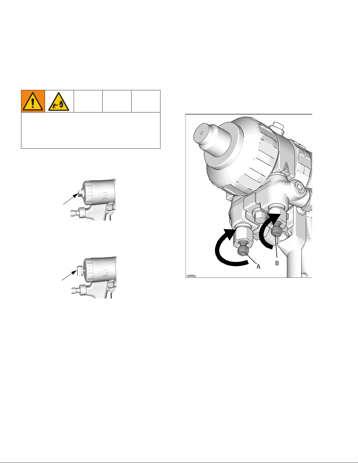
Remove Spray Tip Adapter
1. Perform Pressure Relief Procedure, page 12.
2. Close fluid valves A and B before turning spray tip
adapter (C).
3/32, .094
(2.35)
3A6466A Operation, Repair, Parts 45
Maintenance
Mix Chamber
AF2020
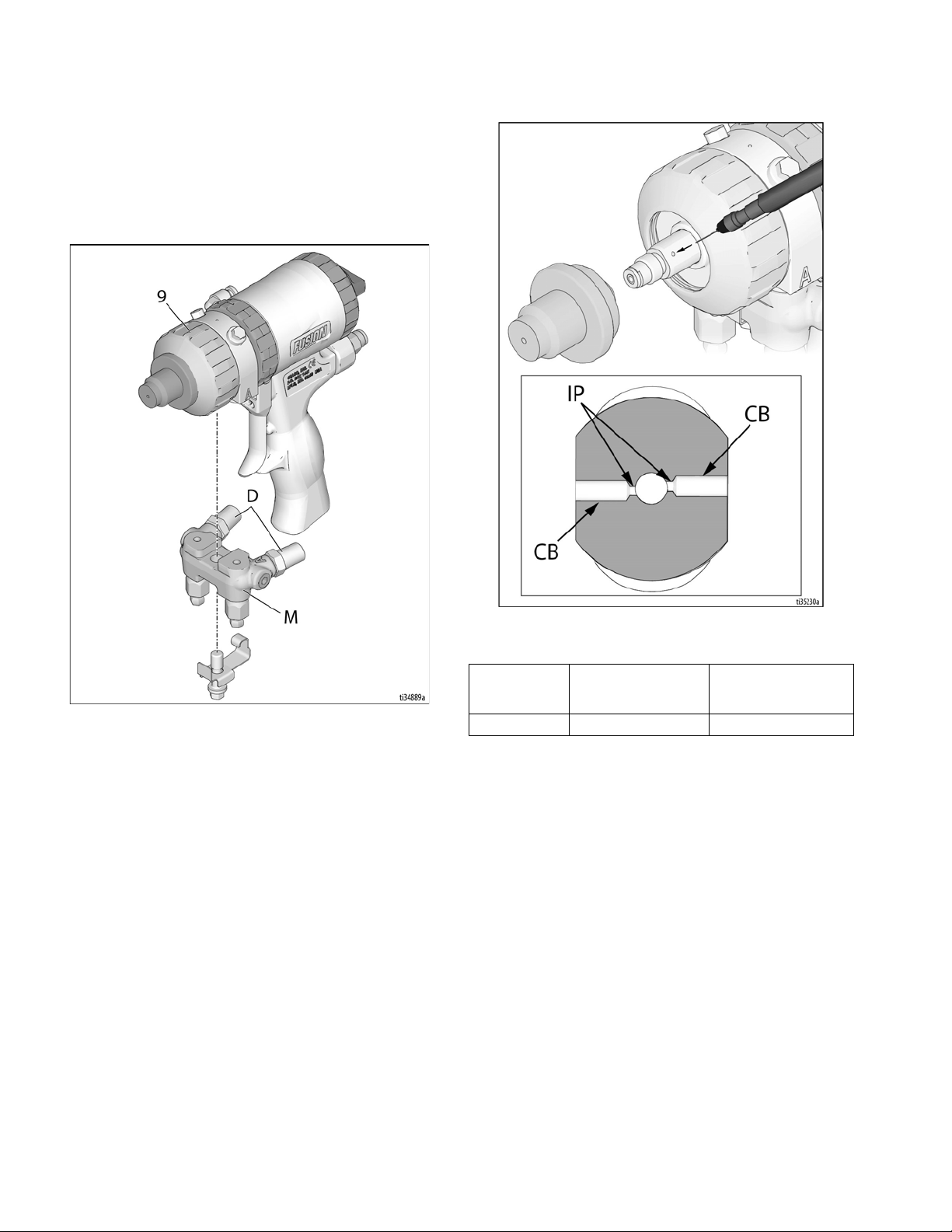
Clean Impingement Ports
1. Follow Pressure Relief Procedure, page 12.
2. Disconnect both air lines and remove fluid manifold
(M).
3.
Flush Gun
, page 44. If gun will not flush, see page 48.
4. Disassemble Front End of Fusion Gun, page 47.
5. Push mix chamber forward until impingement ports
(IP) are visible. See Table 3: Impingement Port
Drill Bit Sizes for appropriate size drill to clean
ports. Also see identification chart under Drill Bit
Kits, page 63. Some mix chambers have counterbored holes (CB) and require two drill sizes to clean
impingement ports completely.
Table 3: Impingement Port Drill Bit Sizes
Mix Chamber
Part No.
AF2020 #76, .020 (0.50) #53, .060 (1.50)
Impingement Port (IP)
Drill Bit Size
in. (mm)
6. Push mix chamber back in position.
7. Reassemble Front End of Fusion Gun, page 47.
8. Attach fluid manifold. Connect air. Gun is ready for
use.
Counterbore (CB)
Drill Bit Size
in. (mm)
Lubrication
Liberally lubricate all o-rings, seals, and threads. Lubricate threads and inside of retaining ring (9). See page
87 to order lubricant.
46 3A6466A Operation, Repair, Parts

Maintenance
Engaged
Disassemble Front End of
Fusion Gun
1. Perform Pressure Relief Procedure, page 12.
2. Flush Gun, page 44.
NOTICE
If lock ring (R) is stuck due to material buildup, do not
force it by turning entire front end. Locating tabs (Z)
may break off. Soak front of gun in solvent to soften
cured material and free lock ring.
3. Unscrew lock ring (R) until front end of gun is loose.
Turn fluid housing (F) 1/8 turn counterclockwise.
Unscrew lock ring completely and remove front end
of gun.
2. Thread on spray tip adapter (10) to mixing chamber,
and press in assembly until spray tip adapter bottoms out on the retaining ring (9). This ensures that
mix chamber is all the way back.
3. Check that o-ring (21) is in position. Liberally lubricate o-ring, threads of lock ring (R) and handle (H),
and outside of lock ring. Orient front end (F) as
required for desired fluid manifold mounting (bottom
mounting is shown). Insert keyed end (W) of mix
chamber in socket (X). Screw lock ring onto handle
as far as possible by hand.
4. Turn fluid housing 1/8 turn clockwise to engage
Reassemble Front End of
Fusion Gun
1. Engage Piston Safety Lock, page 10.
3A6466A Operation, Repair, Parts 47
slots (Y) and tabs (Z). Push on front end to ensure it
is properly seated. Continue screwing lock ring (R)
onto handle (H) very securely. When properly
assembled, lock ring is snug against handle.

Maintenance
Remove Mix Chamber & Side
Seal Cartridges
1. Perform Pressure Relief Procedure, page 12.
2. Remove fluid manifold (M). Leave air connected.
6. Remove spray tip adapter (10) and retaining ring
(9). Inspect o-ring (3) inside retaining ring.
NOTICE
To prevent cross-contamination of side seal cartridges,
do not interchange A component and B component
parts. The A component cartridge is marked with an A.
7. Pull out side seal cartridges (18).
3. Flush gun to remove residual A and B components.
Perform Pressure Relief Procedure, page 12.
4. Shut off air.
8. Pull mix chamber (19) out rear of fluid housing.
Inspect for damage and clean ports, page 46.
Inspect o-ring (23) in front of fluid housing.
NOTICE
To prevent cross-contamination of the gun’s wetted
parts, mix chamber is marked with an A and a notch
(N) on back edge. Be sure the A side of mix chamber is
on the A side of gun.
5. Disassemble Front End of Fusion Gun, page 47.
48 3A6466A Operation, Repair, Parts

Maintenance
B
A
TI2428A
19
N
TI2427A
18e
18c
18d
18b
Reassemble Mix Chamber &
Side Seal Cartridges
1. Apply thin coat of lubricant to mix chamber (19).
Install mix chamber. Etched A and notch (N) must
be on same side as A on fluid housing. Mix chamber
is keyed to fit in fluid housing.
NOTICE
To prevent cross-contamination of side seal cartridges,
do not interchange A component and B component
parts. The A component cartridge is marked with an A.
2. Carefully inspect side seal cartridge o-rings and surfaces. Replace worn or damaged parts. Liberally
lubricate o-rings (18d, 18e) and reassemble. Press
on side seal (18c) to check proper spring (18b)
operation.
3. Liberally lubricate and reinstall side seal cartridges
(18).
4. Lubricate all threads and reinstall retaining ring (9).
Install spray tip adapter (10).
5. Reassemble Front End of Fusion Gun, page 47.
6. Connect air, and trigger the gun a few times to
check for leaks. If either check valve pops out of its
seated position, there is a poor fluid seal on that
side of the mix chamber or side seal/cartridge components. Correct the problem before attaching the
fluid manifold.
7. Attach fluid manifold. Connect air. Return gun to
service.
3A6466A Operation, Repair, Parts 49

Maintenance
Dissassemble Check Valves
NOTE: Before disassembling, press on ball (26c) to test
check valve for proper movement and spring action.
1. Perform Pressure Relief Procedure, page 12.
2. Remove fluid manifold (M). Leave air connected.
Clean Fluid Manifold, page 44.
NOTICE
To prevent cross-contamination of the check valves, do
not interchange A component and B component parts.
The A component check valve is marked with an A.
5. Pry out check valves (26) at notch.
NOTICE
Damaged check valve o-rings (26f, 26g) may result in
external leakage. Replace o-rings if any damage is
seen.
6. Slide filter (26d) off. Clean and inspect parts. Thoroughly inspect o-rings (26f, 26g). If necessary,
remove screw (26b) and disassemble entire check
valve.
3. Flush gun to remove residual A and B components, page
44. Follow
4. Shut off air.
Pressure Relief Procedure
, page 12.
Reassemble Check Valves
1. Reassemble check valves. Screw (26b) should be
flush (within 1/16 in. or 1.5 mm) of housing (26a)
surface. Liberally lubricate o-rings (26f, 26g) and
carefully reinstall in fluid housing.
2. Attach fluid manifold. Connect air. Return gun to
service.
50 3A6466A Operation, Repair, Parts

Maintenance
5
14
TI2430A
16
17
15
TI2431A
TI2432A
TI2430A
5
Piston
1. Perform Pressure Relief Procedure, page 12.
2. Disconnect air (D) and remove fluid manifold (M).
5. Push piston shaft to remove piston (15). Inspect piston o-ring (16) and shaft o-ring (17).
6. Liberally lubricate piston o-rings. Reinstall piston.
Shaft is keyed for proper assembly. Push firmly to
seat piston.
3. Disassemble Front End of Fusion Gun, page 47.
4. Unscrew cylinder cap (5) and inspect o-ring (14).
7. Install cylinder cap (5).
8. Reassemble Front End of Fusion Gun, page 47.
9. Attach fluid manifold. Connect air. Return gun to
service.
3A6466A Operation, Repair, Parts 51

Maintenance
5
1428
24 30 4
TI2433A
Piston Safety Lock
1. Perform Pressure Relief Procedure, page 12.
2. Disconnect air (D) and remove fluid manifold (M).
Air Valve
1. Perform Pressure Relief Procedure, page 12.
2. Disconnect air (D) and remove fluid manifold (M).
3. Unscrew cylinder cap (5). Hold piston stop (28) with
wrench and unscrew from safety lock (4). Inspect
spring (30) and o-rings (14, 24).
4. Liberally lubricate o-rings and reassemble. Clean
threads with solvent or alcohol. Apply
medium-strength sealant to threads on stop (28)
and reassemble.
5. Attach fluid manifold. Connect air. Return gun to
service.
52 3A6466A Operation, Repair, Parts
3. Unscrew air valve plug (2) and remove spring (31).
Using a small diameter tool, push spool (32) out
from front. Inspect o-rings (24).
4. Liberally lubricate o-rings and reassemble. Torque
plug (2) to 125-135 in-lb (14-15 N•m).

Maintenance
Maintenance
LineLazer V 200MMA 1:1
Periodic Maintenance
DAILY: After every use, thouroughly clean gun and
components with acetone.
DAILY: Check air lines for clear passage ways. Ensure
paint is not backed into air hose/fittings.
DAILY: Check engine oil level and fill as necessary.
DAILY: Check hydraulic oil level and fill as necessary.
DAILY: Check hose for wear and damage.
DAILY: Check gun safety for proper operation.
DAILY: Check prime/spray drain valve for proper opera-
tion.
DAILY: Check and fill gas tank
DAILY: Check that displacement pump is tight.
DAILY: Top off TSL level in displacement pump packing
nut to help prevent material buildup on piston rod and
early wear of packing.
WEEKLY/DAILY: Remove any debris from hydraulic
rod.
AFTER EACH 100 HOURS OF OPERATION: Change
engine oil. Reference Honda Engines Owner’s Manual
for correct oil viscosity.
SEMI-ANNUALLY: Check belt wear, replace if necessary.
YEARLY OR 2000 HOURS: Replace belt.
AFTER EACH 500 HOURS OR 3 MONTHS OF OPERATION: Replace hydraulic oil and filter. Use Graco
hydraulic oil 169236 (5 gallon/20 liter) or 207428 (1 gallon/3.8 liter) and filter 246173. Oil change interval
dependent on environmental conditions.
SPARK PLUG: Use only BPR6ES (NGK) or
W20EPR--U (NIPPONDENSO) plug. Gap plug to 0.028
to 0.031 in (0.7 to 0.8 mm). Use spark plug wrench
when installing and removing plug.
Caster Wheel
1. Once each year, tighten nut under dust cap until
spring washer bottoms out, then back off the nut 1/2
to 3/4 turn.
AFTER THE FIRST 20 HOURS OF OPERATION: Drain
engine oil and refill with clean oil. Reference Honda
Engines Owner’s Manual for correct oil viscosity.
WEEKLY: Remove engine air filter cover and clean element. Replace if necessary. If operating in an unusually
dusty environment, check filter daily.
2. Once each month, grease the wheel bearing.
3. Check pin for wear. If pin is worn out, there will be
play in the caster wheel. Reverse or replace the pin
as needed.
4. Check caster wheel alignment as necessary. To
align; see page 24.
3A6466A Operation, Repair, Parts 53

Hydraulic Oil/Filter Change
ti2271a
199
ti2271a
Hydraulic Oil/Filter Change
Removal
1. Perform Pressure Relief Procedure, page 12.
2. Place drip pan or rags under sprayer to catch
hydraulic oil that drains out.
3. Remove drain plug. Allow hydraulic oil to drain.
4. Unscrew filter slowly - oil runs into groove and
drains out rear.
Installation
1. Apply a light film of oil on oil filter gasket. Install
drain plug and oil filter. Tighten oil filter 3/4 turn after
gasket contacts base.
2. Fill tank with Graco synthetic hydraulic oil, ISO 46.
3. Check oil level.
54 3A6466A Operation, Repair, Parts

Troubleshooting
Problem Cause Solution
Gas engine pulls hard (won’t
start).
Engine won’t start. Engine switch is OFF. Turn engine switch ON.
Engine operates, but displacement pump does not
operate.
Displacement pump operates, but output is low on
upstroke.
Hydraulic pressure is too high. Turn hydraulic pressure knob counterclockwise
to lowest setting.
Engine is out of gas. Refill gas tank. See Honda Engines Owner’s
Manual.
Engine oil level is low. Try to start engine. Replenish oil, if necessary.
See Honda Engine Owner’s Manual.
Spark plug cable is disconnected or damaged. Connect spark plug cable or replace spark
plug.
Cold engine. Use choke.
Fuel shutoff lever is OFF. Move lever to ON position.
Oil is seeping into combustion chamber. Remove spark plug. Pull starter 3 to 4 times.
Clean or replace spark plug. Start engine. Keep
sprayer upright to avoid oil seepage.
Pump valve is OFF. Turn pump valve ON.
Pressure setting is too low. Turn pressure adjusting knob clockwise to
increase pressure.
Fluid filter is dirty. Clean filter.
Tip or tip filter is clogged. Clean tip or tip filter. See spray gun manual.
Displacement pump piston rod is stuck due to
dried paint.
Belt worn, broken or off pulley. Replace.
Hydraulic fluid too low. Shut off sprayer. Add Hydraulic fluid.
Hydraulic motor not shifting. Set pump valve OFF. Turn pressure down.
Piston ball is not seating. Service piston ball. See Manual 309277.
Piston packings are worn or damaged. Replace packings. See Manual 309277.
Repair pump. See pump manual.
Turn engine OFF. Pry rod up or down until
hydraulic motor shifts.
Troubleshooting
3A6466A Operation, Repair, Parts 55

Troubleshooting
Problem Cause Solution
Displacement pump operates
but output is low on downstroke and/or on both strokes.
Pump is difficult to prime. Air in pump or hose. Check and tighten all fluid connections.
High engine speed at no load. Mis-adjusted throttle setting. Reset throttle to 3700 - 3800 engine rpm at no
Low stall or run pressure
shown on display.
Excessive paint leakage into
throat packing nut.
Fluid is spitting from gun. Air in pump or hose. Check and tighten all fluid connections. Rep-
Excessive leakage around
hydraulic motor piston rod
wiper.
Strainer is clogged. Clean strainer.
O-ring in pump is worn or damaged. Replace o-ring. See Pump manual 309277.
Intake valve ball is packed with material or is
not seating properly.
Engine speed is too low. Increase throttle setting.
Suction tube air leak. Tighten suction tube.
Pressure setting is too low. Increase pressure.
Fluid filter, tip filter or tip is clogged or dirty. Clean filter.
Large pressure drop in hose with heavy materials.
Intake valve is leaking. Clean intake valve. Be sure ball seat is not
Pump packings are worn. Replace pump packings. See Pump manual.
Paint is too thick. Thin the paint according to the supplier’s rec-
Engine speed is too high. Decrease throttle setting before priming pump.
Worn engine governor. Replace or service engine governor.
New pump or new packings. Pump break-in period takes up to 100 gallons
Faulty transducer. Replace transducer.
Throat packing nut is loose. Remove throat packing nut spacer. Tighten
Throat packings are worn or damaged. Replace packings. See Pump manual 309277.
Displacement rod is worn or damaged. Replace rod. See Pump manual 309277.
Tip is partially clogged. Clear tip.
Fluid supply is low or empty. Refill fluid supply. Prime pump. Check fluid
Insufficient air pressure Increase motor speed, check air caps, check
Piston rod seal worn or damaged. Replace these parts.
Clean intake valve. See Pump manual 309277.
Use larger diameter hose and/or reduce overall
length of hose. Use of more than 100 ft of 1/4
in. hose significantly reduces performance of
sprayer. Use 3/8 in. hose for optimum performance (22 ft minimum).
Reduce engine speed and cycle pump as
slowly as possible during priming.
nicked or worn and that ball seats well. Reassemble valve.
ommendations.
load.
of material.
throat packing nut just enough to stop leakage.
rime pump.
supply often to prevent running pump dry.
air connections.
56 3A6466A Operation, Repair, Parts

Problem Cause Solution
Fluid delivery is low. Pressure setting too low. Increase pressure.
Displacement pump outlet filter (if used) is dirty
or clogged.
Intake line to pump inlet is not tight. Tighten.
Hydraulic motor is worn or damaged. Bring sprayer to Graco distributor for repair.
Large pressure drop in fluid hose. Use larger diameter for shorter hose.
The sprayer overheats. Paint buildup on hydraulic components. Clean.
Oil level is low. Fill with oil.
Excessive hydraulic pump
noise.
Gallon (liter) counter not adding fluid volume.
Sprayer operates, but display
does not.
Distance not adding properly
(Measure mode will be inaccurate and speed will be
wrong).
Mils not calculating or calculates wrong.
Fluid spray starts after spray
icon is shown on display.
Spray icon does not show on
display when fluid is sprayed.
Spray icon is always shown
on display.
Pumps are running at largely
different speeds
Low hydraulic fluid level. Shut off sprayer. Add fluid.
Fluid pressure not high enough. Must be over 800 psi (55 bar) for counter to
Broken or disconnected pump counter wire,
both pumps.
Missing or damaged magnet. Reposition or replace magnet on pump, see
Bad sensor, both pumps. Replace sensor.
Bad connection between control board and
display.
Display damaged. Replace display.
Machine not calibrated. Perform calibration procedure.
Rear tire pressure is too low or too high. Adjust tire pressure to 55 +/- 5 psi (380 +/-
Gear teeth missing or damaged (right side
when standing on platform).
Distance sensor is loose or broken. Reconnect or replace sensor.
Distance sensor. See “Distance counter not operating properly”.
Gallon counter. See “Gallon (liter) counter not adding fluid vol-
Line width not entered. Set line width on main striping screen.
Bad or damaged control board. Replace control board.
Interrupter. Turn screw counterclockwise until spray icon
Loose connector. Check that 5-pin connector and reed switch are
Interrupter (164) is improperly positioned. Turn screw counterclockwise until spray icon
Interrupter is improperly positioned. Turn screw clockwise until spray icon is syn-
Reed switch assembly is damaged. Replace reed switch assembly.
Fluid filter is dirty. Clean filter.
Tip, Filter or Manifold is clogged. Clean components, drill passages.
Displacement pump is stuck. Repair pump, see pump manual.
Impingement ports clogged. Clean, see page 46.
Clean filter.
add.
Check wires and connections. Replace any
broken wires
Parts manual (Pump parts) for magnet location.
Remove display and reconnect.
34kPa).
Replace distance gear/wheel hub.
ume.”
synchronizes with fluid spray, page 22.
properly connected.
synchronizes with fluid spray.
chronized with fluid spray, page 22.
Troubleshooting
3A6466A Operation, Repair, Parts 57

Troubleshooting
Problem Cause Solution
AUTO GUN MODE
Auto Gun won’t actuate when
the red button is pressed.
Line Spacing is not accurate Wrong line pattern loaded. Reload the correct pattern.
Battery won’t stay charged. Accessories are left on and drain the battery
Auto Gun won’t shut off Cable is kinked. Repair or replace cable.
Gun is not activated. Press the 1 or 2 button on control to activate a
gun.
Cable is not adjusted properly. Adjust Cable to properly actuate gun trigger,
page 23.
Not on main striping screen. Go to main striping screen on control to Actu-
ate Auto Guns.
Low Speed Shut off is enabled. Disable Low Speed Shutoff, page 39.
Battery Voltage is too low. Check battery voltage on Diagnostic Screen,
page 13, or with Volt meter. If below 11.5V,
charge battery or replace battery.
Cable is not adjusted properly. Adjust Cable to properly actuate gun trigger,
page 23.
Red button is broken. Test button functionality in Diagnostic screen,
page 13. Replace if broken.
Auto Gun Cable is broken or extremely kinked
resulting in too much drag.
Solenoid wire is disconnected or broken. Check Wiring Diagram, page 88, repair or
Fuse to battery is removed or blown. Check and replace fuse.
Solenoid is jammed. Spray Lubrication on solenoid plunger.
Solenoid is failed. Check resistance across solenoid wires. Resis-
Control board is failed. Replace Control board.
Gun is not receiving air. Check air pressure. Open air valve on gun.
Air pressure too low. Increase motor speed, check air connections &
Machine is out of calibration. Calibrate the machine, page 13.
when unit is not running.
Throttle is not set high enough. Make sure engine is being ran above 3300
Power consumption from accessories is higher
than engine output.
Wiring is broken or disconnected. Check Wiring Diagram, page 88, repair or
Charger is not working. Check Charging state in diagnostics, page 35,
Solenoid is jammed. Lubricate solenoid plunger, Check for solenoid
Low air pressure. Increase motor speed, check air connections.
Replace Auto Gun Cable.
replace wires if necessary.
tance should be between .2 and .26 ohms. If
it’s not, replace solenoid.
air cap.
Turn off accessories when machine is not in
use.
rpm, NO LOAD for proper power supply.
Reduce accessories or charge battery when
necessary.
replace wires if necessary.
to see if charger is properly working. Replace
Board.
damage.
58 3A6466A Operation, Repair, Parts

Problem Cause Solution
LAYOUT MODE
No dots or poor dots in Layout
and Marking Mode.
Troubleshooting
Too small of Dot setting. Increase Dot size, page 35.
Gun is not activated. Press the 1 or 2 button on control to activate a
gun.
Cable is not adjusted properly. Adjust Cable to properly actuate gun trigger,
page 23.
Tip clog. Clear tip or Replace tip.
Battery voltage is too low. Charge battery or replace battery.
3A6466A Operation, Repair, Parts 59

Gun Troubleshooting
Gun Troubleshooting
1.
Perform
2. Check all possible problems and causes before disassembling gun.
Gun does not fully actuate
when triggered.
Fluid does not spray when
gun is fully actuated.
Gun actuates slowly. Plugged muffler (22). Clean, page 44.
Gun delays, then actuates
abruptly.
Loss of flat pattern. Plugged spray tip. Clean incompatible solvent, page 48.
Leakage between flat tip and
mix chamber.
Pressure imbalance. Plugged impingement ports. Clean, page 46.
Pressure Relief Procedure, page 12
.
NOTICE
To prevent cross-contamination of the gun’s wetted
parts, do not interchange A component and B component parts.
Problem Cause Solution
Safety lock engaged. Disengage safety lock, page 10.
Plugged muffler (22). Clean, page 44.
Damaged air valve o-rings (24). Replace, page 52.
Low air pressure. Check air connections, increase throttle.
Closed fluid valves (12b). Open.
Plugged impingement ports. Clean, page 46.
Plugged check valves (26). Clean, page 50.
Damaged piston o-rings (16, 17). Replace, page 51.
Dirty air valve, or damaged o-rings (24). Clean air valve or replace o-rings, page 52.
Low air pressure. Check air connections, increase throttle.
Cured material around side seals (18). Inspect side seals (18c) and mix chamber (19)
for scratches. Replace, page 48.
Retaining ring (9) not bottomed out. Tighten retaining ring until bottomed out.
Worn tip. Replace, page 48.
Dirty mix chamber nozzle. Clean, page 48.
Tip not seated properly. Reassemble, page 48.
Damaged/missing o-ring (40). Replace, page 48.
Plugged check valves (26). Clean, page 50.
Viscosities not equal. Adjust temperature to compensate.
Hoses are plugged. Flush system with acetone, replace hoses.
60 3A6466A Operation, Repair, Parts

Problem Cause Solution
Gun Troubleshooting
A and/or B fluid in gun air section.
Fluid mist from mix chamber
or spray tip adapter.
Excessive cleanoff air when
fluid valves are closed and
gun is triggered.
Fluid does not shut off when
fluid valves are closed.
Burst of air from muffler when
gun is triggered.
Steady air leakage from muffler.
Air leakage from front air
valve.
Air leak around lock ring. Damaged o-ring (21). Replace, page 48.
Cannot tighten retaining ring
(9) until it bottoms out.
Streaking in spray pattern. Too small spray orifice. Increase tip size.
Damaged side seals (18c). Replace, page 48.
Damaged mix chamber (19). Replace, page 48.
Damaged side seal o-rings (18d, 18e). Replace, page 48.
Tightened spray tip adapter with fluid valves
(12b) open.
Damaged side seals (18c). Replace, page 48.
Damaged side seal o-rings (18d, 18e). Replace, page 48.
Damaged mix chamber (19). Replace, page 48.
Damaged/missing fluid housing o-ring (23). Replace, page 48.
Damaged fluid valves (12b). Replace.
Normal. No action required.
Damaged air valve o-rings (24). Replace, page 52.
Damaged piston o-rings (16, 17). Replace, page 51.
Damaged air valve o-rings (24). Replace, page 52.
Spray tip adapter (10) assembled before
retaining ring (9).
Too low pressure. Increase spray pressure.
Too cold of material. Check material recommended spray tempera-
Close valves first.
Install retaining ring (9) first, then spray tip
adapter (10), page 49.
ture.
3A6466A Operation, Repair, Parts 61

Gun Repair Kits
Gun Repair Kits
Read the chart left to right and top to bottom to find the quantity of each part in the kits.
Ref.
No.
3 248137 (6) 1
14 248136 (6) 1
16 248135 (6) 1
17 248134 (6) 1
18c 2
18d 248130 (6) 4 4
18e 248128 (6) 2 2 2
21 248132 (6) 1
23 248131 (6) 1
24 246354 (6) 5
26f 248133 (6) 2 2
26g 248129 (6) 2 2
40 246360 (3)
Bulk O-ring
Kits, (qty)
246347
Side Seal
Cartridge
O-ring Kit
246348
Side
Seal Kit
246351
Check
Valve
O-ring Kit
246355
Complete
O-ring Kit
Check Valve Filter Screen Kits
Kits include 10 filter screens.
40 mesh filter screen is standard with gun.
246357 40 mesh (.015 in., 375 micron)
246358 60 mesh (.010 in., 238 micron)
246359 80 mesh (.007 in., 175 micron)
62 3A6466A Operation, Repair, Parts

Drill Bit Kits
1 in.
(25.4 mm)
1 in.
(25.4 mm)
For cleaning gun ports and orifices. Illustrations are for
diameter comparison. Actual length may vary.
NOTE: Not all sizes are used with your gun.
Drill Bit Kits
Kit Part No. Qty in Kit
Drill Bit Size
nominal in. mm
246624 3 3/32 .094 2.39
246627 6 #53 .060 1.52
246631 6 #76 0.20 0.51
Drill Bit Kit
119386
Kit includes 20 cleanout drill bits ranging in sizes of #61
through #80.
Illustration
Air Purge Handle Cleanout
Drill Kit
248969
Kit includes all 5 drill bits of extra long length needed to
clean out the air passages in the Air Purge gun handle
and fluid housing. See Clean Passages, page 45.
3A6466A Operation, Repair, Parts 63

Notes
Notes
64 3A6466A Operation, Repair, Parts

LineLazer V 200MMA 1:1
PAGES 76 & 78
PAGES 68 & 74
PAGES 80 & 84
PAGE 66
PAGE 68
PAGE 82
LineLazer V 200MMA 1:1
3A6466A Operation, Repair, Parts 65

Parts Drawing - Frame Assembly
Torque to 45-55 ft-lbs
(61.0-74.5 N·m)
Torque to 17-23 ft-lbs
(23.0-31.1 N·m)
Rear tire pressure 58-62 psi
(3.9-4.2 bar)
Torque to 190-210 in-lbs
(21.4-23.7 N·m)
Torque to 130-150 in-lbs
(14.6-16.9 N·m)
1
2
3
4
5
1
2
2
2
2
2
2
2
2
3
4
4
5
Parts Drawing - Frame Assembly
66 3A6466A Operation, Repair, Parts

Parts List - Frame Assembly
Parts List - Frame Assembly
Ref Part Description Qty
1 287623 FRAME, linestriper, painted 1
101566 NUT, lock 12
6
7 193405 AXLE 1
9 198891 BRACKET 1
10 198930 ROD, brake (includes 12) 1
11 198931 BEARING 1
12 114808 CAP, vinyl 1
13 195134 SPACER 1
14 113961 SCREW, cap, hex hd 1
15 112960 SCREW, flange, hex 5
16 111040 NUT, lock, insert, nylock, 5/16 8
17 111020 WHEEL, pneumatic w/o sensor ring 1
255162 WHEEL, pneumatic w/ sensor ring 1
18 112405 NUT, lock 2
19 112825 WASHER 4
20 114648 CAP, dust 2
21 15J088 SHIELD, distance sensor 1
22 15K452 SPACER, round 1
23 15K357 SENSOR, distance 1
24 108868 CLAMP, wire 2
25 260212 SCREW, hex washer hd, thd form 2
26 15J578 GEAR, signal 1
27 15K700 RING, sensor gear 1
29 240991 BRACKET, caster, front 1
31 114982 SCREW, cap, flange hd 6
34 114549 WHEEL, pneumatic 1
39 17H528 BRACKET, gun arm 1
40 24Y665 FRAME, handle upright, painted 1
41 17Y059 BRACE, right, painted 1
42 17Y058 BRACE, left, painted 1
43 128977 SCREW, cap button hd 6
48 17J125 BRACKET, slide 2
49 24Y641 BAR, handle 1
50 17J136 SCREW, hex, flange head 8
102 196176 ADAPTER, nipple 2
105 114659 GRIP, handle 2
106 237686 WIRE, ground 1
107 107257 SCREW, thread forming, hex hd 1
108 194310 LEVER 1
109 17J123 PLATE, cover 1
112 110982 SCREW, cap, hex 2
115 17J407 ARM, extension, bar, weldment 1
123 191239 HOSE, cpld, 3/8” x 11’10” 2
124 245227 HOSE, cpld, 1/4” x 7’ 2
125 24V064 HOSE, suction / drain (includes
125a-125i)
125a 15F149 TUBE, suction 2
125b 194306 HOSE, fluid 2
125c 198119 FITTING, elbow, barbed 2
125d 101818 CLAMP, hose 2
125f 16X071 TUBE, drainline 2
125g 278722 GASKET, pail 2
125h 248008 HOSE, cpld, 1/4” x 44” 2
125i 196180 BUSHING 2
127 15F369 BOX 1
129 189919 BLANK, label, kit 2
146 120151 PLUG, tube 2
157 114271 STRAP, retaining 2
158 108471 KNOB, pronged 1
159 111145 KNOB, pronged 2
Ref Part Description Qty
160 404989 STRAP, tie 6
161 17K394 LABEL, gmax warning fire & skin 1
162 115077 PAIL, plastic 2
163 24U241 KIT, pail, cover 2
165 17J408 ARM, extension, third gun 1
201 107257 SCREW, thd, forming 11
217 110755 WASHER, plain 4
247 100023 WASHER, flat 7
252 100527 WASHER, plain 6
258 17y409 BRACKET, mount, pump, hydraulic 1
267 17Y047 BRACKET, mount, pump, hydraulic,
right
274 17J549 BRACKET, reservoir 1
276 15F441 BRACKET, frame 1
277 119696 SPRING, extension 1
297 17K377 COVER, battery, painted 1
308 17K392 LABEL, safety, warning 1
310 17K397 LABEL, notice, electrical usage 1
321 16T580 BAND, clamping, bead tank 1
322 16T763 FRAME, tank, LL200, painted, left 1
324 16T762 FRAME, bead tank, LL200, painted,
right
325 16T579 BRACKET, compressor, LL200 1
326 16T629 TANK, bead 1
327 111193 SCREW, cap, flang hd 6
328 115087 PLUG, tubing 2
329 121488 SCREW, hex hd, flanged 6
330 16T593 BRACKET, bead tank, LL200,
painted
331 120757 SCREW, carriage 4
372 125626 SCREW, hex hd, flanged 4
399 16A719 WASHER, flat 1
400 197449 SPACER 1
402 114653 SCREW, cap, flange head 1
403 17Y328 LABEL, identification, letter “A” 4
404 17Y329 LABEL, identification, letter “B” 4
407 17Y054 PLATE, bucket holder 1
408 17P800 BUMPER, (.88 wide x .17 thick) 4
409 17Y350 BRACKET, reservoir, support, rear,
MMA
410 100133 WASHER, lock 3/8 2
411 100575 SCREW, cap, hex hd 2
412 17Y055 SUPPORT, reservoir, front 1
415 100731 WASHER 1
2
416 17C466 TUBE, poly, heat-shrink, green 2
417 17C465 TUBE, poly, heat-shrink, blue 2
428 120140 VALVE, ball, assembly 1
429 110982 SCREW, cap, hex hd 2
432 125112 SCREW, cap, btn hd, 5/16 x 1 4
434 25N603 KIT, bracket, 5 gallon, dual color 1
435 17N536 HOLDER, bucket 4
436 867517 SCREW, hex head, 3/8-16 x 3.5” 8
437 125205 NUT, lock, nylon, 3/8-16 8
439 15R409 PAD, non-slip, brake 4
440 131818 MANIFOLD, flow drivider, hydraulic 1
441 17Y487 LABEL, instructions, valve 1
Replacement safety labels, tags, and cards are available
at no cost.
1
1
1
1
3A6466A Operation, Repair, Parts 67

Parts Drawing - Gun Arm & Gun Trigger
142
131
133
134
135
136
126
130
132
133
134
137
144
138
140
139
120
130e
130a
ti28049a
Torque to 18-22 in-lbs
(2.0-2.4 N·m)
1
1
Parts Drawing - Gun Arm & Gun Trigger
68 3A6466A Operation, Repair, Parts

Parts List
Gun Holder and Arm Gun Trigger
Parts List
Ref. Part Description Qty.
6 101566 NUT, lock (not shown) 2
31 114982 SCREW, cap, flange hd (not shown) 2
39 17H528 BRACKET, gun arm (not shown) 1
115 17J407 ARM, extension, bar (not shown) 1
116 17J424 BAR, height adjustment, assy 1
116a 17J139 BAR, gun, height, adjustment 1
116b 113428 SCREW, mach, hex, hd 3
116c 17J153 BRACKET, gun holder 1
118 24Y645 KIT, clamp, double wing nut 1
119 25A529 ARM, gun holder, linelazer (includes
151)
119a 24Y919 BRACKET, cable 1
119b* 17Y418 HOLDER, gun 1
119c 17J575 FASTENER, special 1
119d* 119664 BEARING, sleeve 1
119e 17J576 SPACER, special 1
119f 119647 SCREW, cap, socket 2
119g 17H673 STUD, cable, gun 1
119h 15F214 LEVER, actuator 1
119i 17H674 ADAPTER, cable, gun 1
119j 102040 NUT, lock hex 2
119k 15F209 STUD, pull, trigger 1
119l 17J145 ARM, holder, gun 1
119m* 15F750 KNOB, holder, gun 1
119n 131827 BRACKET, gun, support 1
120 25A488 CABLE, gun, manual (includes 126,
151)
121 188135 GUIDE, cable 1
122 25E471 GUN, air purge, MMA 1
124 245227 HOSE, coupled 1/4” x 7’ 2
128 16P136 LABEL, safety, warning, iso 1
151 126111 RETAINER, circlip, external, 8mm 2
158 108471 KNOB, pronged 1
159 111145 KNOB, pronged (not shown) 2
165 17J408 ARM, extension, third gun (not
shown)
211 25A487 CABLE, gun, automatic (includes
151, 212, 213)
225 17C043 LABEL, number “1” 1
17C046 LABEL, number “2” 1
294 115483 NUT, lock 2
347 100020 WASHER, lock 2
348 116876 WASHER, flat 2
353 16T646 SWITCH, air 1
354 16T804 BRACKET, switch, air 1
355 16T771 BOOT, button, push 1
356 16R963 KIT, gun, bead, sub-assembly 1
357 16U274 HOSE, pneumatic 1
359 16T816 BRACKET, switch, air 1
361 104387 SCREW, mach, pnh 2
362 16V046 RESTRICTOR, air flow, adjustable 2
364 16V047 HOSE, pneumatic 2
365 116610 SCREW, machm phil, pan, #10 2
375 190010 TUBE 2
Ref. Part Description Qty.
120 25A488 CABLE, gun, manual (includes 126,
151)
126 15F624 NUT, cable, gun (knurled) 2
130 25A636 BRACKET, trigger w switch 1
130a 276907 BRACKET, magnet 1
130e 17J237 SWITCH, reed 1
131 198896 BLOCK, mounting 1
132 245676 HANDLE 1
133 198895 PLATE, lever, pivot 2
1
134 111017 BEARING, flange 2
135 116941 SCREW, shoulder, skt hd 1
136 116969 NUT, lock 1
137 112381 SCREW, mach, pan head 1
138 117268 BRACKET, interrupter 1
139 117269 SPRING 1
140 128803 SCREW, thd forming, hex washer 1
142 117317 SCREW, plastite, pan head 2
144 17K587 LABEL, notice, adjustment 1
1
1
1
1
* Included in Gun Holder Repair Kit 17Y878
Replacement safety labels, tags, and cards are available
at no cost.
3A6466A Operation, Repair, Parts 69

Cutaway View - Gun
NOTE: Part numbers and descriptions are on page 72.
E
F
C
G
H
Cutaway View - Gun
70 3A6466A Operation, Repair, Parts

Parts Drawing - Gun
Torque to 125-135 in-lb (14-15 N•m).
Torque to 20-30 in-lb (2.3-3.4 N•m).
Torque to 235-245 in-lb (26.6-27.7 N•m).
Torque to 35-45 in-lb (4-5 N•m).
Torque to 32-40 ft-lb (43-54 N•m).
123
4
5
1
1
1
2
2
3
3
4
4
4
4
5
Parts Drawing - Gun
3A6466A Operation, Repair, Parts 71

Parts List - Gun
Parts List - Gun
Ref. Part No. Description Qty.
1 17Y546 HANDLE 1
2 15B208 PLUG, air valve 1
3 248137 O-RING; PTFE; package of 6 1
4 15B206 LOCK, safety 1
5 15B204 CAP, cylinder 1
6 192272 PIN 1
7 15B215 RING, lock 1
8 15B223 VALVE, cleanoff air 1
9 15B211 RING, retaining 1
10 17Y509 ADAPTER, Tip Guard 1
11 246491 HOUSING, fluid 1
12 17Y678 MANIFOLD, fluid, 2-hose;
includes 12a-12g
12a† . MANIFOLD 1
12b 246356 . VALVE, fluid 2
12c 100139 . PLUG, pipe; 1/8-27 npt 2
12d 15B221 . BOLT; 5/16-24 1
12e 151519 . FITTING, nipple, reducing 2
12g 15B993 . SPRING, ring, lock 1
13 15B209 TRIGGER 1
14* 248136 O-RING, cylinder cap;
package of 6
15 15B203 PISTON 1
16* 248135 O-RING, piston; package of 6 1
17* 248134 O-RING, piston shaft;
package of 6
18 246349 CARTRIDGE, seal, A side, SST;
includes 18a-18e
246350 CARTRIDGE, seal, B side, SST;
includes 18a-18e
18a† . CARTRIDGE BODY 1
18b 117491 . SPRING 1
18c*† . SEAL KIT; see page 86 1
18d* 248130 . O-RING, cartridge body;
package of 6
18e* 248128 . O-RING, side seal;
package of 6
19 AF2020 CHAMBER, mix, round 1
20 15C480 WASHER, wave 1
21* 248132 O-RING; package of 6 1
22 119626 MUFFLER 1
23* 248131 O-RING; package of 6 1
24* 246354 O-RING; package of 6 1
25 100846 FITTING, grease 1
26 17Y963 VALVE, check, A side; includes
26a-26g
1
1
1
1
1
1
1
1
Ref. Part No. Description Qty.
17Y964 VALVE, check, B side; includes
26a† . HOUSING 1
26b† 15B214 . SCREW; 5/16-18 x
26c 257420 . BALL; carbide; package of 10 1
26d . SCREEN; see page 62. 1
26e 117490 . SPRING 1
26f* 248133 . O-RING, check valve face;
26g* 248129 . O-RING, check valve housing;
27 116550 RING, retaining 1
28 15B205 STOP, piston 1
29 203953 SCREW; 10-24 x 3/8 in. (10 mm) 1
30 114070 SPRING 1
31 117485 SPRING 1
32 15B202 SPOOL, valve 1
33 100721 PLUG, pipe; 1/4-18 npt;
35 117509 QUICK-DISCONNECT, male, air;
36 222385 CARD, Medical Alert; not shown 1
37 15B689 COVER, grease fitting 1
39 248018 TIP, extension, seal, flat; package
40* 246360 O-RING; PTFE; flat tip models
43 117661 VISE, pin; dual reversible chucks;
46 117792 GREASE GUN; not shown 1
50 112307 ELBOW, street; 1/8 npt (m x f);
58 118486 FITTING, elbow, push to connect 1
See Detail Views - Gun, page 73, for additional parts.
* These parts are only available in repair kits. To select
a kit, refer to page 62.
† These parts are not available individually.
Included in Safety Stop Assembly 248064 (includes 1
of item 24).
Sealed, non-adjustable
Replacement safety labels, tags, and cards are avail-
able at no cost.
26a-26g
1/2 in. (13 mm)
package of 6
package of 6
round and flat pattern guns only
1/4 npt(m); round and flat pattern
guns only
of 5
only; package of 3
see Supplied Tools, page 73.
round and flat pattern guns only
1
1
1
1
1
1
1
1
1
2
72 3A6466A Operation, Repair, Parts

Detail Views - Gun
35 (Ref)
33 (Ref)
12d (Ref)
52
TI2647A
Flush Manifold Detail
1
1
53
43
54
Supplied Tools
TI3870A
Torque to 125-135 in-lb (14-15 N•m).
1
Mix Chamber
O-ring Detail
Detail Views - Gun
Ref. Part No. Description Qty.
52 15B817 MANIFOLD, gun flush; round and
1
flat pattern guns only
53 117642 NUT DRIVER, hex; 5/16 1
54 118575 SCREWDRIVER; 1/8 blade 1
55 172479 TAG, warning; not shown 1
57 117773 GREASE CARTRIDGE; 3 oz;
1
not shown; MSDS sheet available
at www.graco.com
Replacement safety labels, tags, and cards are available
at no cost.
3A6466A Operation, Repair, Parts 73

Parts Drawing - Handle/Controls
Do not allow the solenoid wires
to make a sharp bend as shown.
Doing so may lead to wire
breakage. Place an approximate
0.75" radius bend in the wires
exiting the solenoid.
0.75"
Torque to 35-45 ft-lbs
(47.4-61.0 N·m)
Torque to 190-210 in-lbs
(21.4-23.7 N·m)
Torque to 365-385 in-lbs
(41.2-43.4 N·m)
Torque to 25-30 in-lbs
(2.8-3.3 N·m)
Torque to 18-22 in-lbs
(2.0-2.4 N·m)
Torque to 45-55 ft-lbs
(61.0-74.5 N·m)
Torque to 130-150 in-lbs
(14.6-16.9 N·m)
Torque to 65-75 in-lbs
(7.3-8.4 N·m)
1
2346789
6
Parts Drawing - Handle/Controls
NOTICE
74 3A6466A Operation, Repair, Parts

Parts List - Handle/Controls
Parts List - Handle/Controls
Ref Part Description Qty
40 24Y665 FRAME, handle upright, painted 1
48 17J125 BRACKET, slide 2
50 17J136 SCREW, hex, flange head 8
104 17J120 PLATE, control 1
105 114659 GRIP, handle 2
106 237686 WIRE, ground, assy. 1
107 107257 SCREW, thd forming 1
109 17J123 PLATE, cover 1
112 102040 NUT, lock, hex 4
113 17V517 COVER, control, usb, painted 1
114 128978 SCREW, mach, slot hex wash hd 12
129 189919 KIT, blank, label 1
146 120151 PLUG, tube 2
147 17J134 CONTROL, throttle 1
148 25N791 BOX, control assembly (includes 149) 1
149 17H701 GROMMET, oval 1
149 16W408 KNOB, t-handle, 1/4-20 thd stud 2
166 17V520 LABEL, usb 1
169 17J617 WIRE, harness 1
201 107257 SCREW, thd forming 10
205 24X370 BATTERY, 22 AH, sealed (includes
373, 374)
206 17H644 SHELF, battery 1
207 126949 STRAP, battery 1
208 17H650 COVER, solenoid, automatic 1
209 25A486 SOLENOID, module 1
210 24Y777 BRACKET, solenoid 1
211 24A487 CABLE, gun, solenoid, auto (includes
151, 212, 213)
212 128711 PIN, clevis, 5/16 1
213 15R598 CLIP, cotter, hairpin 1
217 110755 WASHER, plain 2
218 121114 NUT, hex, self locking 2
219 128712 CAP, dust cover 2
233 101962 SCREW, set, sch 2
Ref Part Description Qty
234 25A255 SHAFT, flexible 1
263 15H108 LABEL, safety, warning, pinch 1
268 17H698 BUSHING, pressure control, mount 1
269 119775 NUT, panel 1
270 115999 RING, retaining 1
272 16Y408 KNOB, pressure control 1
273 15A464 LABEL, control 1
290 128856 CLAMP 2
291 114687 CLIP, retainer 2
294 115483 NUT, lock 2
295 17K378 LABEL, brand, LLV, battery cover 1
296 17K379 LABEL, brand, console, shroud 1
297 17K377 COVER, battery, painted 1
298 16W503 LABEL, safety, ground 1
310 17K397 LABEL, notice, electrical usage 1
311 17K396 LABEL, safety 1
373 128131 SCREW, cap, hex head 2
374 111307 WASHER, lock, external 2
380 189930 LABEL, caution 1
392 172084 BOARD, assembly (includes 166, 393,
1
393 17V519 SCREW, pan hd 2
394 131718 COVER, dust, usb 2
403 128855 SWITCH, rocker 1
404 17J126 BRACKET, shroud 1
405 17J128 BRACKET, switch 1
407 120593 SCREW, mach, torx pan hd 4
410 109466 NUT, lock, hex 2
1
412 17J456 LABEL, control 1
434 15K162 BLOCK 1
435 17J236 SWITCH, push button 1
Replacement safety labels, tags, and cards are available
at no cost.
394)
1
3A6466A Operation, Repair, Parts 75

Parts Drawing - Filters A & B
Torque to 130-150 in-lbs
(14.6-16.9 N·m)
Torque to 150 ft-lbs
(203.3 N·m)
Torque to 40 ft-lbs
(54.2 N·m)
Torque to 25 ft-lbs
(33.8 N·m)
123
4
Parts Drawing - Filters A & B
76 3A6466A Operation, Repair, Parts

Parts List - Filters A & B
Parts List - Filters A & B
Ref. Part Description Qty.
51
52
53
54
55
56
57
58
59
60
61
17K166 MANIFOLD, filter 2
196179 FITTING, elbow, street 1
15C765 CAP, filter 2
16C766 TUBE, diffusion 2
24V455 FILTER, fluid 2
117285 PACKING, o-ring 2
111801 SCREW, cap, hex hd 4
248024 TRANSDUCER, pressure control 2
111457 PACKING, o-ring 2
15G331 PLUG, pipe 4
287879 VALVE, drain, assy 2
Ref. Part Description Qty.
62
63
64
65
66
67
68
123
125
153 245226 HOSE, coupled 3/8 x 3’ 1
413 17Y104 BRACKET, manifold 1
196178 ADAPTER, nipple 2
114708 SPRING, compression 2
196181 FITTING, nipple 2
15G563 HANDLE, valve 2
116424 NUT, cap 2
193709 SEAT, valve 2
193710 SEAL, seat, valve 2
191239 HOSE, cpld, 3/8” x 11’10” 2
24V064 HOSE, suction/drain 2
3A6466A Operation, Repair, Parts 77

Parts Drawing - Fluid Pumps A & B
Torque to 130-150 in-lbs
(14.6-16.9 N·m)
Torque to 150 ft-lbs
(203.3 N·m)
Torque to 40 ft-lbs
(54.2 N·m)
Torque to 25 ft-lbs
(33.8 N·m)
123
4
Parts Drawing - Fluid Pumps A & B
78 3A6466A Operation, Repair, Parts

Parts List - Fluid Pumps A & B
Parts List - Fluid Pumps A & B
Ref. Part Description Qty.
25
52
62
69
93
95 116551 RING, retainer 1
96
97
100 277068 PUMP, displacement 1
101 193394 NUT, retaining 1
112 102040 NUT, lock, hex 2
138* 106276 SCREW, cap, hex head 1
149 119841 FITTING, tee, branch, str thd 1
159* 155685 PACKING, o-ring 1
153 245226 HOSE, coupled 3/8 x 3’ 1
173 100139 PLUG, pipe 1
179*‡ 108014 PACKING, o-ring 1
183 15A726 NUT, jam 1
186* 112342 BEARING, rod 2
187‡ 112561 PACKING, block 1
213*‡ 117283 PACKING, o-ring 2
217 117607 FITTING, elbow, std thd 2
220*‡ 117739 WIPER, rod 1
222 287186 KIT, repair, magnet 1
230 15A728 MANIFOLD, adapter 1
243* 178179 WASHER, sealing 1
239 287176 KIT, repair, hose 2
288754 KIT, repair, trip rod/piston 1
196179 FITTING, elbow, street 2
196178 ADAPTER, nipple 2
246176 KIT, repair, sleeve, cylinder 1
197443 PIN, pump 1
119720 SWITCH, reed w/ connector 1
114528 SCREW, mach, phillips, pnhd 2
Ref. Part Description Qty.
244*‡ 178207 BEARING, piston 1
245*‡ 178226 SEAL, piston 1
258 17Y049 BRACKET, mount, pump, left 1
259 117328 FITTING, nipple, straight 1
260 117441 VALVE, ball 1
261 107210 SCREW 4
263* 15H108 LABEL, warning, pinch point 2
265 15B063 LABEL, safety, warning, hot surface 1
266 24X474 COVER, assy, pump rod 1
267 17Y047 BRACKET, mount, pump, right 1
403 17Y328 LABEL, “A” 1
404 17Y329 LABEL, “B” 1
410 100133 WASHER, lock 3/8 2
411 100575 SCREW, cap, hex 2
412 15F519 TUBE, hydraulic, supply 1
414 131774 SWITCH, reed 1
425 131817 FITTING, tee 2
430 17Y306 HOSE, hydraulic, supply 2
442 15G784 HOSE, coupled 2
501 131814 ACCUMULATOR, diaphragm 2
502 115829 ADAPTER, swivel, 90° 2
503 113584 TEE, branch 2
504 131815 ADAPTER, straight 2
* Included in Trip Rod/Piston/Cap Repair Kit 288754
‡ Included in Hydraulic Seal Repair Kit 246174
Replacement safety labels, tags, and cards are available
at no cost.
3A6466A Operation, Repair, Parts 79
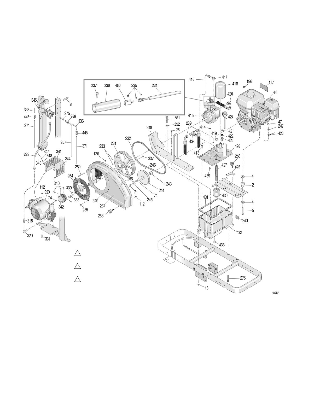
Parts Drawing - Engine & Compressor
Torque to 115-135 in-lbs
(12.9-15.2 N·m)
Torque to 190-210 in-lbs
(21.4-23.7 N·m)
Torque to 58-62 in-lbs
(6.5-7.0N·m)
1
2
3
Parts Drawing - Engine & Compressor
80 3A6466A Operation, Repair, Parts

Parts List - Engine & Compressor
Parts List - Engine & Compressor
Ref. Part Description Qty.
2 15E888 DAMPENER, motor mount 4
108851 WASHER, plain 8
4
5 113664 SCREW, cap, hex hd 4
8 111194 SCREW, cap, flang hd 2
16 111040 NUT, lock, insert, nylock, 5/16 2
25 260212 SCREW, hex, washer hd, thd form 2
44 116080 ENGINE 1
47 110838 NUT, lock 4
71 108842 SCREW, cap, hex hd 1
74 117632 KEY, square, 3/16 x 1.25 1
112 102040 NUT, lock, hex 1
117 194126 LABEL, warning 1
136 116969 NUT, lock 2
196 114956 TERMINAL, wire tap, insulated 1
231 16U205 PULLEY, fan 1
232 119433 BELT 1
233 120087 SCREW, set, 1/4 x 1/2 2
234 25A255 SHAFT, flexible, hydraulic control 1
235 112303 SCREW, set, socket w/ patch 3
236 15C958 GUARD, pressure control 1
237 112166 SCREW, cap, sch 7
239 15C364 HOSE, hydraulic, return 2
240 15K440 LABEL, brand, GH EH cooling 1
243 15B314 SLEEVE, motor shaft 1
244 15E758 PULLEY, 5.50 in. 1
245 112717 WASHER 1
246 100002 SCREW, set, sch 1
247 100023 WASHER, flat 4
248 288261 RAIL, belt guard, assy 1
249 288734 GUARD, belt (includes 136, 250,
254, 255)
250 119434 SCREW, shoulder, skt hd 1
251 802277 SCREW, machine 2
252 100527 WASHER, plain 2
253 15D862 NUT, hand 2
254 117284 GRILL, fan, guard 1
255 115477 SCREW, mach, torx pan hd 4
256 16M768 LABEL, warning, iso, pinch hazard 2
257 17H689 LABEL, brand, LLV 200HS, shroud 1
275 120981 SCREW, mach, hex washer hd 2
315 156971 FITTING, nipple, short 1
320 187357 ELBOW, street 1
323 126789 COMPRESSOR, piston air, 1.7 hp (6
cfm)
331 120757 SCREW, carriage 4
Ref. Part Description Qty.
332 16T939 HOSE, coupled 1
333 126833 SCREW, shoulder, socket head 2
336 16U273 HOSE, pneumatic 3
337 112958 NUT, hex, flanged, 3/8-16 2
339 120376 KEY, square .188 1
340 120087 SCREW, set, 1/4 x 1/2 4
341 16X197 GUARD, pneumatic pump 1
342 16X252 COUPLER, roller chain 1
343 867489 SCREW, pan head, phillips 3
344 16C394 LABEL, safety, warning, entangle 1
345 17Y644 TANK, pressure, MMA 1
347 100020 WASHER, lock 5
348 116876 WASHER, flat 5
357 16U274 HOSE, pneumatic 1
369 115287 FITTING, Y tube 1
371 17C065 TUBE, air, 1/4 OD 3
375 190010 TUBE 2
445 16F366 FITTING, 1/4 ptc to 1/4 ptc, fda 2
413 119426 SCREW, mach, hex washer hd 8
414 107188 PACKING, o-ring 4
415 287179 KIT, repair, pump (includes 235,
414, 419, 429, 480)
416 246167 KIT, repair, case drain 1
417 110792 FITTING, elbow, male, 90° 1
418 246173 KIT, repair, oil filter 1
419 156401 PACKING, o-ring 1
420 116829 FITTING, elbow, hydraulic 1
421 100084 BALL, metallic 1
422 116967 SPRING, compression 1
423 240997 CONDUCTOR, ground 1
1
424 120726 CAP, breather, filler 1
425 198841 RETAINER, ball, pressure bypass 1
426 15M057 COVER, reservoir, 200HS 1
427 15E587 TUBE, suction 1
428 15E476 BRACKET, retainer, motor 1
429 117471 SCREW, mach, hex flat head 4
430 116919 FILTER, screen, suction 1
431 120604 GASKET, reservoir 1
432 15J513 TANK, reservoir 1
433 101754 PLUG, pipe, 3/8 nptf 1
434 126061 FITTING, #8 JIC tee, swivel 1
445 16F366 FITTING, 1/4 ptc to 1/4 ptc 2
1
Replacement safety labels, tags, and cards are available
at no cost.
1
3A6466A Operation, Repair, Parts 81
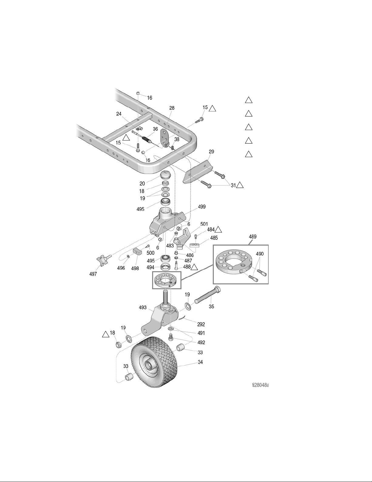
Parts Drawing - EZ Align Swivel Wheel
Torque to 17-23 ft-lbs
(23.0-31.1 N·m)
Torque to 190-210 in-lbs
(21.4-23.7 N·m)
Torque to 23-27 ft-lbs
(31.1-36.6 N·m)
Torque to 60-80 in-lbs
(6.7-9.0 N·m)
Torque to 17-23 ft-lbs
(23.0-31.1 N·m)
12345
2
1
4
5
2
3
Parts Drawing - EZ Align Swivel Wheel
82 3A6466A Operation, Repair, Parts

Parts List - EZ Align Swivel Wheel
Parts List - EZ Align Swivel Wheel
Ref Part Description Qty
101566 NUT, lock 2
6
112960 SCREW, cap, flange hd 3
15
111040 NUT, lock, insert, nylon, 5/16 3
16
112405 NUT, lock 2
18*‡
112825 WASHER 4
‡
19*
114648 CAP, dust 1
20*
‡
24 108868 CLAMP, wire 1
15F910 BRACKET, cable 1
‡
28
29 240991 BRACKET, caster, front 1
31 114982 SCREW, cap, flange hd 2
193658 SPACER, seal 2
‡
33*
34* 114549 WHEEL, pneumatic 1
35* 113471 SCRE, cap, hex hd 1
241445 CABLE 1
‡
36
114802 STOP, wire 1
38
‡
17H489 LABEL, disk adjustment 1
292*
‡
114548 BEARING, bronze 2
483*
‡
110754 SCREW, cap, sch 2
484*
‡
Ref Part Description Qty
193662 STOP, wedge 1
‡
485*
15J603 SPACER, round 1
487*
‡
120476 BOLT, shoulder 1
‡
488*
17H486 DISK, adjuster, assembly 1
489*
‡
17G762 SCREW, disk adjuster 1
490*
‡
113962 WASHER 1
‡
491*
492* 114681 SCREW, cap, hex hd 1
17H485 FORK 1
‡
493*
113484 SEAL, grease 1
494*
‡
113485 BEARING, cup/cone 2
‡
495*
112776 WASHER, plain 1
496*
‡
181818 KNOB, pronged 1
497*
‡
193661 JAW 1
‡
498*
15G952 CASTER 1
499*
‡
108483 SCREW, shoulder 1
500*
‡
* Included in Swivel Wheel Repair Kit 240719
‡ Included in Swivel Wheel Repair Kit 241105
3A6466A Operation, Repair, Parts 83

Parts Drawing - Pressure Tank
Parts Drawing - Pressure Tank
84 3A6466A Operation, Repair, Parts

Parts List - Presssure Tank
Parts List - Presssure Tank
Ref Part Description Qty
156971 FITTING, nipple, short 2
1
187357 ELBOW, street 1
2
16W088 GAUGE, air pressure 1
3
194666 LABEL, LineLazer, EZ bead system 1
4
17C463 FITTING, tee, street 1
5
16U375 REGULATOR 1
6
7 126804 REGULATOR, unloader 1
162453 FITTING, 1/4 npsm x 1/4 npt 1
8
9 16U174 TANK, pressure 1
10 101971 PLUG, pipe 1
118486 FITTING, elbow, push 1
11
12 113321 FITTING, elbow, tube 1
Ref Part Description Qty
13 116720 COUPLER, quick disconnect 1
104655 GAUGE, press air 1
14
15B565 VALVE, ball 1
15
070408 SEALANT, pipe, sst 1
16
156823 FITTING, union, swivel 1
17
116504 FITTING, tee, run 1
18
110249 ADAPTER, male elbow, 90° 1
19
122946 VALVE, shut off 1
20
101566 NUT, lock (not shown) 2
21
128637 FITTING, ptc, straight, 1/4 1
22
17Y520 LABEL, instructions, valve position 1
23
3A6466A Operation, Repair, Parts 85

Accessories - Gun
Accessories - Gun
Stainless Steel Side Seal Kits
Kits include a packing o-ring for each stainless steel seal.
Kit Part No. Description No. of Seals Per Kit
246348 SEAL KIT, SST 2
277299 SEAL KIT, SST 50
Polycarballoy Side Seal Kits
Kits include a packing o-ring for each polycarballoy seal. The optional high wear, non-metallic polycarballoy seals are
for alternate fluids.
Kit Part No. Description No. of Seals Per Kit
249990 SEAL KIT, Polycarballoy 2
277298 SEAL KIT, Polycarballoy 50
86 3A6466A Operation, Repair, Parts

Accessories - Gun
TI4165a
TI4211b
Gun Cover
244914 Covers
Keeps gun clean while spraying. Pack of 10.
Lubricant for Gun Rebuild
248279, 4 oz (113 gram) [10]
High adhesion, water resistant, lithium-based lubricant.
SDS sheet available at www.graco.com.
Grease Cartridge for Gun
Shutdown
248280 Cartridge, 3 oz [10]
Specially formulated low viscosity grease flows easily
through gun passages, to prevent 2 component curing
and keep fluid passages clean. See page 28.
Flushing Manifold
Solvent Flush Canister Kit
248139, 1 qt (0.95 liter) Solvent Cup
Complete with15B817 Flushing Manifold to flush gun
with solvent. Portable for remote flushing. See manual
309963.
Solvent Flush Pail Kit
248229 5.0 gal. (19 liter) Pail
Includes flush manifold with individual A and B shutoff
valves, and air regulator. See manual 309963.
15B817 Manifold Block
See ref. no. 52, page 73.
Gun Cleaning Kit
15D546
Kit includes 11 tools and brushes to clean the gun.
3A6466A Operation, Repair, Parts 87
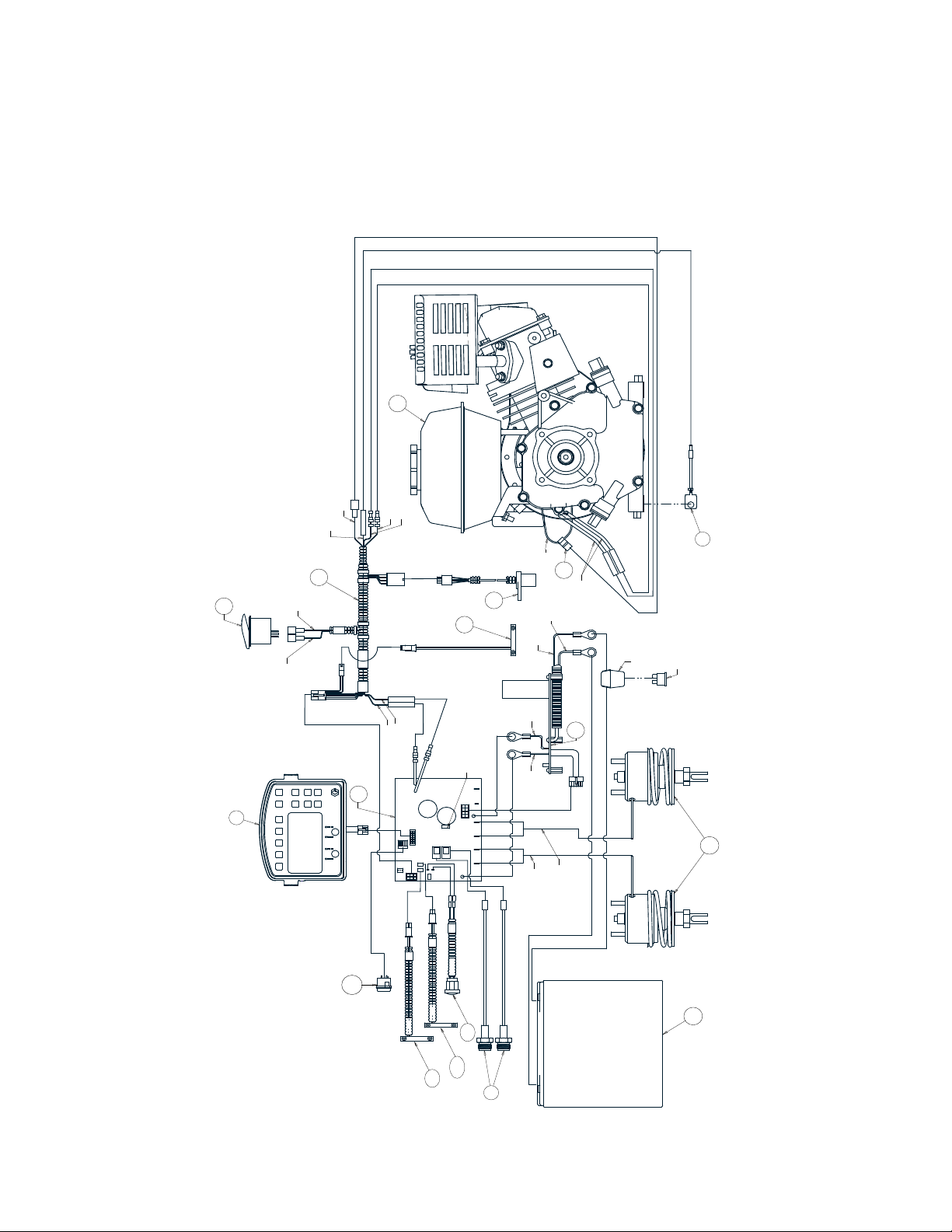
Wiring Diagram
58
196
44
YELLOW
GREY
23
RED
BLACK
46
YELLOW
WHITE/YELLOW
RED
WHITE/RED
ENGINE
STOP SWITCH
148
-
+
CONTROL
BOARD
WHITE/RED
RED
PROGRAMMING PORT
GUN 1
GUN 2
BLACK
RED
CHARGER
BOARD
30A AUTOMOTIVE FUSE
REGULAR ATO
FUSE HOLDER
209
205
PUMP B
PUMP A
PUMP B
HAND LEVER
169
96
392
WHITE/YELLOW
YELLOW
409
403
408
ti35361a
PUMP A
435
130e
414
Wiring Diagram
88 3A6466A Operation, Repair, Parts
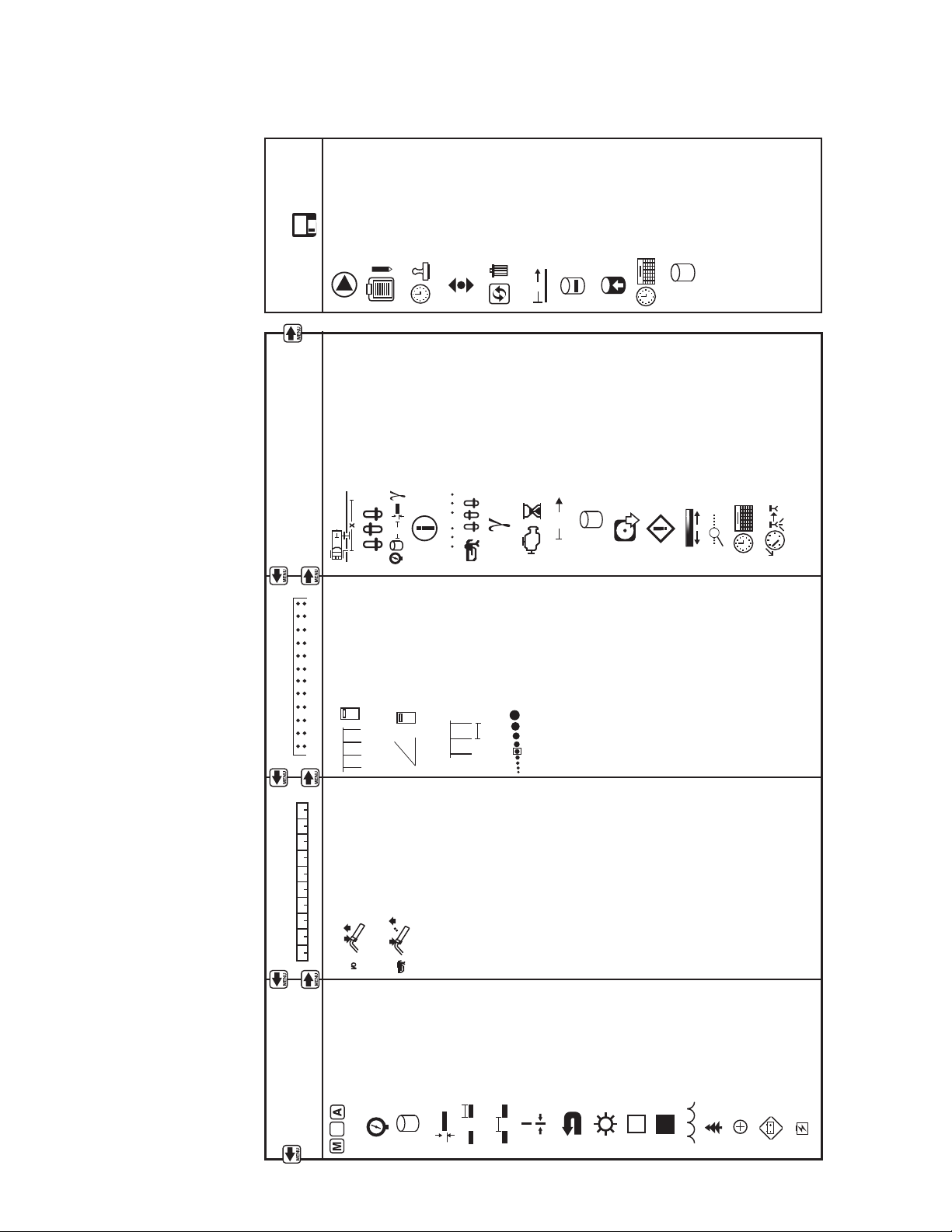
World Symbol Key
MENU SCREENS
STRIPING MODE MEASURE MODE
LAYOUT MODE SETTINGS/DATA
DATA LOGGING
MANUAL,
SEMI- AUTOMATIC or
AUTOMATIC MODE
PRESSURE
GALLONS/LITERS
LINE THICKNESS
PAINT LENGTH
SPACE LENGTH
LINE WIDTH
EXIT
YELLOW
PRESS TO START/STOP
HOLD TO SPRAY A DOT
STALL CALCULATOR
ANGLE CALCULATOR
STALL WIDTH
DOT SIZE SELECTOR
CALIBRATE START RECORDING
NEW JOB
JOBS
TIME STAMP
SCROLL
SETTINGS
UNITS
INFORMATION
& LIFE DATA
MARKER LAYOUT MODE
GUN SETTINGS
SPECIFIC GRAVITY
ENGINE HOURS
TOTAL DISTANCE
TOTAL GALLONS
SOFTWARE REV
ERROR CODES
CONTRAST
DIAGNOSTICS
TIME AND DATE
LOW SPEED SHUTOFF
I/O
....
....
ș
÷
x
+
÷
x
+
-
1 2 3 4 5 6 7 8 9 10
TOTALGALLONS/
LITERS
X'
X'
A
TIME AND DATE
S
WHITE
BLUE
GREEN
RED
BATTERY LOW
BLACK
BATTERY CHARGING
DELETE
DISTANCE PAINTED
GALLONS OF LINE
PAINTED
X
GALLONS OF
STENCIL PAINTED
World Symbol Key
ti28025a
LLV GLOBAL SYMBOL KEY
3A6466A Operation, Repair, Parts 89

Technical Specifications
WARNING: This product can expose you to chemicals known to the State of
California to cause cancer and birth defects or other reproductive harm. For
more information go to www.P65Warnings.ca.gov.
CALIFORNIA PROPOSITION 65
Technical Specifications
LineLazer V 200 MMA (Models 17Y234, 17Y513, 17Y233, 17Y514)
U.S. Metric
Dimensions
Height (with handle bar down)
Width Unpackaged - 34.25 in.
Length Unpackaged - 68.75 in.
Weight (dry - no paint) Unpackaged - 554 lbs
Noise (dBa)
Sound Power per ISO 9614:
Sound Pressure per ISO 9614:
Vibration (m/s2) (8 hours daily exposure)
Hand Arm (per ISO 5349) Left hand 1.71
Whole Body (per ISO 2631)
Power Rating (Horse Power)
Power Rating (Horse Power) per SAE J1349
Maximum Delivery
Maximum Tip Size
1 gun
2 gun
Inlet paint strainer 16 mesh 1190 micron
Outlet paint strainer 40 mesh 297 micron
Pump inlet size 1 in. NSPM (m)
Pump outlet size 3/8 NPT (f)
Maximum working pressure 3300 psi 228 bar, 22.8 MPa
Maximum fluid working pressure 3300 psi 228 bar, 22.8 MPa
Maximum free-flow delivery 2.15 gpm 8.14 lpm
Cycles per gallon/liter 62 cpg 16.4 cpl
Hydraulic reservoir capacity 1.25 gallons 4.73 liters
Hydraulic pressure 1825 psi 124 bar
Electrical Capacity 84 W@ 3600 rpm
Battery 12V, 22Ah, Sealed lead acid, Deep cycle
Unpackaged - 44.5 in.
Packaged - 52.5 in.
Packaged - 37.0 in.
Packaged - 73.5 in.
Packaged - 621 lbs
99.0
85.5
Right hand 2.23
0.4
6.5 HP @ 3600 rpm 4.84 kW @ 3600 rpm
2.15 gpm 8.14 lpm
.047
.035
Unpackaged - 113.03 cm
Packaged - 133.35 cm
Unpackaged - 87.0 cm
Packaged - 93.98 cm
Unpackaged - 174.63 cm
Packaged - 186.69 cm
Unpackaged - 251 kg
Packaged - 282 kg
Wetted Parts: PTFE, Nylon, polyurethane, V-Max,
UHMWPE, fluoroelastomer, acetal, leather, tungsten
carbide, stainless steel, chrome plating, nickel-plated
carbon steel, ceramic
90 3A6466A Operation, Repair, Parts

Technical Specifications - Gun
Technical Specifications - Gun
Category Data
Maximum Fluid Working Pressure 3500 psi (24.5 MPa, 245 bar)
Minimum Air Inlet Pressure 80 psi (0.56 MPa, 5.6 bar)
Maximum Air Inlet Pressure 130 psi (0.9 MPa, 9 bar)
Maximum Fluid Temperature 200° F (94° C)
Air Inlet Size 1/4 push-to-connect
A Component Inlet Size 1/4 NPT
B Component Inlet Size 1/4 NPT
Sound Pressure 81.1 dB(A), using AR5252 at 100 psi (0.7 MPa, 7 bar)
Sound Power, measured per ISO 9416-2 91.0 dB(A), using AR5252 at 100 psi (0.7 MPa, 7 bar)
Dimensions 7.5 x 8.1 x 3.3 in. (191 x 206 x 84 mm)
Weight 2.5 lb (1.1 kg)
Wetted Parts
All other brand names or marks are used for identification purposes and are trademarks of their respective owners.
Aluminum, stainless steel, carbon steel, carbide,
chemically resistant o-rings
End of Product Life
At the end of the product’s useful life, dismantle and
recycle it in a responsible manner.
• Perform the Pressure Relief Procedure, page 12.
• Drain and dispose of fluids according to applicable
regulations. Refer to the material manufacturer’s
Safety Data Sheet.
• Remove motors, batteries, circuit boards, LCDs
(liquid crystal displays), and other electronic
components. Recycle according to applicable
regulations.
• Do not dispose of batteries or electronic
components with household or commercial waste.
• Deliver remaining product to a recycling facility.
3A6466A Operation, Repair, Parts 91

Graco Standard Warranty
Graco warrants all equipment referenced in this document which is manufactured by Graco and bearing its name to be free from defects in
material and workmanship on the date of sale to the original purchaser for use. With the exception of any special, extended, or limited warranty
published by Graco, Graco will, for a period of twelve months from the date of sale, repair or replace any part of the equipment determined by
Graco to be defective. This warranty applies only when the equipment is installed, operated and maintained in accordance with Graco’s
recommendations.
This warranty does not cover, and Graco shall not be liable for general wear and tear, or any malfunction, damage or wear caused by faulty
installation, misapplication, abrasion, corrosion, inadequate or improper maintenance, negligence, accident, tampering, or substitution of
non-Graco component parts. Nor shall Graco be liable for malfunction, damage or wear caused by the incompatibility of Graco equipment with
structures, accessories, equipment or materials not supplied by Graco, or the improper design, manufacture, installation, operation or
maintenance of structures, accessories, equipment or materials not supplied by Graco.
This warranty is conditioned upon the prepaid return of the equipment claimed to be defective to an authorized Graco distributor for verification of
the claimed defect. If the claimed defect is verified, Graco will repair or replace free of charge any defective parts. The equipment will be returned
to the original purchaser transportation prepaid. If inspection of the equipment does not disclose any defect in material or workmanship, repairs
will be made at a reasonable charge, which charges may include the costs of parts, labor, and transportation.
THIS WARRANTY IS EXCLUSIVE, AND IS IN LIEU OF ANY OTHER WARRANTIES, EXPRESS OR IMPLIED, INCLUDING BUT NOT
LIMITED TO WARRANTY OF MERCHANTABILITY OR WARRANTY OF FITNESS FOR A PARTICULAR PURPOSE.
Graco’s sole obligation and buyer’s sole remedy for any breach of warranty shall be as set forth above. The buyer agrees that no other remedy
(including, but not limited to, incidental or consequential damages for lost profits, lost sales, injury to person or property, or any other incidental or
consequential loss) shall be available. Any action for breach of warranty must be brought within two (2) years of the date of sale.
GRACO MAKES NO WARRANTY, AND DISCLAIMS ALL IMPLIED WARRANTIES OF MERCHANTABILITY AND FITNESS FOR A
PARTICULAR PURPOSE, IN CONNECTION WITH ACCESSORIES, EQUIPMENT, MATERIALS OR COMPONENTS SOLD BUT NOT
MANUFACTURED BY GRACO. These items sold, but not manufactured by Graco (such as electric motors, switches, hose, etc.), are subject to
the warranty, if any, of their manufacturer. Graco will provide purchaser with reasonable assistance in making any claim for breach of these
warranties.
In no event will Graco be liable for indirect, incidental, special or consequential damages resulting from Graco supplying equipment hereunder, or
the furnishing, performance, or use of any products or other goods sold hereto, whether due to a breach of contract, breach of warranty, the
negligence of Graco, or otherwise.
written
Graco Information
For the latest information about Graco products, visit www.graco.com.
For patent information, see www.graco.com/patents.
TO PLACE AN ORDER, contact your Graco distributor or call 1-800-690-2894 to identify the nearest distributor.
All written and visual data contained in this document reflects the latest product information available at the time of publication.
GRACO INC. AND SUBSIDIARIES • P.O. BOX 1441 • MINNEAPOLIS MN 55440-1441 • USA
Copyright 2018, Graco Inc. All Graco manufacturing locations are registered to ISO 9001.
Graco reserves the right to make changes at any time without notice.
Original instructions. This manual contains English. MM 3A6466
Graco Headquarters: Minneapolis
International Offices: Belgium, China, Japan, Korea
www.graco.com
Revision
A, April 2019
 Loading...