

Graco LineLazer IV 3900, LineLazer IV R300, LineLazer IV 5900, FieldLazer R300 Repair And Parts Manual
Repair - Parts
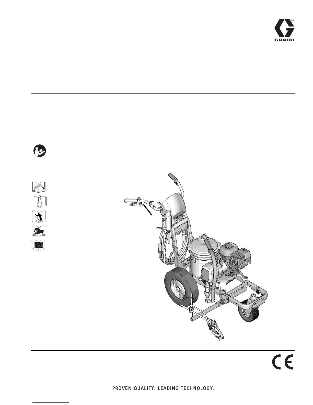
ti25623a
LineLazer™ IV 3900, R300, 5900, and
FieldLazer R300 Airless Line Stripers
- For application of line stripling materials -
3300 psi (22.8 MPa, 228 bar) Maximum Working Pressure
Important Safety Instructions
Read all warnings and instructions in this manual and in LineLazer,
FieldLazer Operation manual. Be familiar with the controls and the
proper usage of the equipment. Save these instructions
311017
312540
310643
311254
311020Y
EN
309055
311049

Contents
Models . . . . . . . . . . . . . . . . . . . . . . . . . . . . . . . . . . . 3
3900 . . . . . . . . . . . . . . . . . . . . . . . . . . . . . . . . . . 3
R300 . . . . . . . . . . . . . . . . . . . . . . . . . . . . . . . . . . 3
5900 . . . . . . . . . . . . . . . . . . . . . . . . . . . . . . . . . . 3
Warnings . . . . . . . . . . . . . . . . . . . . . . . . . . . . . . . . . 4
Tip Selection . . . . . . . . . . . . . . . . . . . . . . . . . . . . . . 6
Maintenance . . . . . . . . . . . . . . . . . . . . . . . . . . . . . . . 7
Pressure Relief Procedure . . . . . . . . . . . . . . . . . 7
Troubleshooting . . . . . . . . . . . . . . . . . . . . . . . . . . . 8
Bearing Housing and Connecting Rod . . . . . . . . 11
Removal . . . . . . . . . . . . . . . . . . . . . . . . . . . . . . 11
Installation . . . . . . . . . . . . . . . . . . . . . . . . . . . . . 11
Drive Housing . . . . . . . . . . . . . . . . . . . . . . . . . . . . 12
Removal . . . . . . . . . . . . . . . . . . . . . . . . . . . . . . 12
Installation . . . . . . . . . . . . . . . . . . . . . . . . . . . . . 12
Pinion Assembly/Clutch Armature/Clamp . . . . . 13
Clutch Housing . . . . . . . . . . . . . . . . . . . . . . . . . . . 15
Removal . . . . . . . . . . . . . . . . . . . . . . . . . . . . . . 15
Engine . . . . . . . . . . . . . . . . . . . . . . . . . . . . . . . . . . . 16
Removal . . . . . . . . . . . . . . . . . . . . . . . . . . . . . . 16
Pressure Control . . . . . . . . . . . . . . . . . . . . . . . . . . 17
On/Off Switch . . . . . . . . . . . . . . . . . . . . . . . . . . 17
Pressure Control . . . . . . . . . . . . . . . . . . . . . . . . . . 18
Control Board . . . . . . . . . . . . . . . . . . . . . . . . . . 18
Installation . . . . . . . . . . . . . . . . . . . . . . . . . . . . . 18
Pressure Control Transducer . . . . . . . . . . . . . . 18
Installation . . . . . . . . . . . . . . . . . . . . . . . . . . . . . 18
Pressure Adjust Potentiometer . . . . . . . . . . . . . 18
Installation . . . . . . . . . . . . . . . . . . . . . . . . . . . . . 18
Trigger Sensor Adjustment . . . . . . . . . . . . . . . . . 19
Distance Sensor Adjustment . . . . . . . . . . . . . . . . 19
Gear Alignment . . . . . . . . . . . . . . . . . . . . . . . . . 19
Sensor Height Adjustment . . . . . . . . . . . . . . . . . 19
Control Board Diagnostics . . . . . . . . . . . . . . . . . . 20
Digital Display Messages . . . . . . . . . . . . . . . . . 20
Displacement Pump . . . . . . . . . . . . . . . . . . . . . . . . 21
Removal . . . . . . . . . . . . . . . . . . . . . . . . . . . . . . 21
Parts - LineLazer IV . . . . . . . . . . . . . . . . . . . . . . . . 22
Parts - Drive and Pinion Housing Assemblies . . 23
Parts Drawing - LineLazer IV . . . . . . . . . . . . . . . . 24
Parts List - LineLazer IV . . . . . . . . . . . . . . . . . . . . 25
Parts Drawing - Line Lazer IV . . . . . . . . . . . . . . . . 26
Models 248862, 248866 . . . . . . . . . . . . . . . . . . 26
Parts List - LineLazer IV . . . . . . . . . . . . . . . . . . . . 27
Parts Drawing - LineLazer IV . . . . . . . . . . . . . . . . 28
Models 248862, 248866 . . . . . . . . . . . . . . . . . . 28
Parts List - LineLazer IV . . . . . . . . . . . . . . . . . . . . 29
Models 248862, 248866 . . . . . . . . . . . . . . . . . . 29
Parts Drawing - LineLazer IV . . . . . . . . . . . . . . . . 30
Models 248862, 248866 . . . . . . . . . . . . . . . . . . 30
Parts List - LineLazer IV . . . . . . . . . . . . . . . . . . . . 31
Models 248862, 248866 . . . . . . . . . . . . . . . . . . 31
Parts Drawing - LineLazer IV . . . . . . . . . . . . . . . . 32
Models 248862, 248866 . . . . . . . . . . . . . . . . . . 32
Parts List - LineLazer IV . . . . . . . . . . . . . . . . . . . . 33
Models 248862, 248866 . . . . . . . . . . . . . . . . . . 33
Pressure Control Wiring Diagram . . . . . . . . . . . . 34
Technical Data . . . . . . . . . . . . . . . . . . . . . . . . . . . . 35
Dimensions . . . . . . . . . . . . . . . . . . . . . . . . . . . . 36
Graco Standard Warranty . . . . . . . . . . . . . . . . . . . 37
2 311020Y

Models
ti6394a
3900
Models
248862
248863
249008
249009
248864
248865
R300
24M605
24M607
5900
248866
248867
249010
249011
248868
248869
311020Y 3
Warnings
WARNINGWARNINGWARNING
WARNING
Warnings
The following warnings are for the setup, use, grounding, maintenance, and repair of this equipment. The exclamation point symbol alerts you to a general warning and the hazard symbols refer to procedure-specific risks. When
these symbols appear in the body of this manual or on warning labels, refer back to these Warnings. Product-specific
hazard symbols and warnings not covered in this section may appear throughout the body of this manual where
applicable.
FIRE AND EXPLOSION HAZARD
Flammable fumes, such as solvent and paint fumes, in work area can ignite or explode. To help
prevent fire and explosion:
• Use equipment only in well ventilated area.
• Do not fill fuel tank while engine is running or hot; shut off engine and let it cool. Fuel is flammable
and can ignite or explode if spilled on hot surface.
• Eliminate all ignition sources; such as pilot lights, cigarettes, portable electric lamps, and plastic
drop cloths (potential static arc).
• Keep work area free of debris, including solvent, rags and gasoline.
• Do not plug or unplug power cords, or turn power or light switches on or off when flammable fumes
are present.
• Ground equipment and conductive objects in work area. See Grounding instructions.
• Use only grounded hoses.
• Hold gun firmly to side of grounded pail when triggering into pail.
• Stop operation immediately if there is static sparking or you feel a shock. Do not use equipment
until you identify and correct the problem.
• Keep a fire extinguisher in work area.
CARBON MONOXIDE HAZRD
Exhaust contains poisonous carbon monoxide, which is colorless and odorless. Breathing carbon
monoxide can cause death.
• Do not operate in an enclosed area.
SKIN INJECTION HAZARD
High-pressure fluid from gun, hose leaks, or ruptured components will pierce skin. This may look like
just a cut, but it is a serious injury that can result in amputation. Get immediate surgical treatment.
• Do not spray without tip guard and trigger guard installed.
• Engage trigger lock when not spraying.
• Do not point gun at anyone or at any part of the body.
• Do not put your hand over the spray tip.
• Do not stop or deflect leaks with your hand, body, glove, or rag.
• Follow Pressure Relief Procedure when you stop spraying and before cleaning, checking, or
servicing equipment.
• Tighten all fluid connections before operating the equipment.
• Check hoses and couplings daily. Replace worn or damaged parts immediately.
PRESSURIZED EQUIPMENT HAZARD
Fluid from the gun/dispense valve, leaks, or ruptured components can splash in the eyes or on skin
and cause serious injury.
• Follow Pressure Relief Procedure in this manual, when you stop spraying and before cleaning,
checking, or servicing equipment.
• Tighten all fluid connections before operating the equipment.
• Check hoses, tubes, and couplings daily. Replace worn or damaged parts immediately.
4 311020Y

Warnings
WARNINGWARNINGWARNING
WARNING
PRESSURIZED ALUMINUM PARTS HAZARD
Use of fluids that are incompatible with aluminum in pressurized equipment can cause serious
chemical reaction and equipment rupture. Failure to follow this warning can result in death, serious
injury, or property damage.
• Do not use 1,1,1--trichloroethane, methylene chloride, other halogenated hydrocarbon solvents or
fluids containing such solvents
• Do not use chlorine bleach.
• Many other fluids may contain chemicals that can react with aluminum. Contact your material
supplier for compatibility.
EQUIPMENT MISUSE HAZARD
Misuse can cause death or serious injury.
• Do not operate the unit when fatigued or under the influence of drugs or alcohol.
• Do not exceed the maximum working pressure or temperature rating of the lowest rated system
component. See Technical Data in all equipment manuals.
• Use fluids and solvents that are compatible with equipment wetted parts. See Technical Data in all
equipment manuals. Read fluid and solvent manufacturer’s warnings. For complete information
about your material, request MSDS from distributor or retailer.
• Do not leave the work area while equipment is energized or under pressure.
• Turn off all equipment and follow the Pressure Relief Procedure when equipment is not in use.
• Check equipment daily. Repair or replace worn or damaged parts immediately with genuine
manufacturer’s replacement parts only.
• Do not alter or modify equipment. Alterations or modifications may void agency approvals and
create safety hazards.
• Make sure all equipment is rated and approved for the environment in which you are using it.
• Use equipment only for its intended purpose. Call your distributor for information.
• Route hoses and cables away from traffic areas, sharp edges, moving parts, and hot surfaces.
• Do not kink or ever bend hoses or use hoses to pull equipment.
• Keep children and animals away from work area.
• Comply with all applicable safety regulations.
BURN HAZARD
Equipment surfaces and fluid that’s heated can become very hot during operation. To avoid severe
burns:
• Do not touch hot fluid or equipment.
MOVING PARTS HAZARD
Moving parts can pinch, cut or amputate fingers and other body parts.
• Keep clear of moving parts.
• Do not operate equipment with protective guards or covers removed.
• Pressurized equipment can start without warning. Before checking, moving, or servicing equipment,
follow the Pressure Relief Procedure and disconnect all power sources.
PERSONAL PROTECTIVE EQUIPMENT
Wear appropriate protective equipment when in the work area to help prevent serious injury, including
eye injury, hearing loss, inhalation of toxic fumes, and burns. Protective equipment includes but is not
limited to:
• Protective eyewear, and hearing protection
• Respirators, protective clothing, and gloves as recommended by the fluid and solvent manufacturer.
RECOIL HAZARD
Gun may recoil when triggered. If you are not standing securely, you could fall and be seriously injured.
CALIFORNIA PROPOSITION 65
The engine exhaust from this product contains a chemical known to the State of California to cause
cancer, birth defects or other reproductive harm.
This product contains a chemical known to the State of California to cause cancer, birth defects or
other reproductive harm. Wash hands after handling.
311020Y 5

Tip Selection
in.
(cm)
in.
(cm)
in.
(cm)
Tip Selection
in.
(cm)
LL5213* 2 (5)
LL5215* 2 (5)
LL5217 4 (10)
LL5219 4 (10)
LL5315 4 (10)
LL5317 4 (10)
LL5319 4 (10)
LL5321 4 (10)
LL5323 4 (10)
LL5325 4 (10)
LL5327 4 (10)
LL5329 4 (10)
LL5331 4 (10)
LL5333 4 (10)
LL5335 4 (10)
LL5355 4 (10)
LL5417 6 (15)
LL5419 6 (15)
LL5421 6 (15)
LL5423 6 (15)
LL5425 6 (15)
LL5427 6 (15)
LL5429 6 (15)
LL5431 6 (15)
LL5435 6 (15)
LL5621 12 (30)
LL5623 12 (30)
LL5625 12 (30)
LL5627 12 (30)
LL5629 12 (30)
LL5631 12 (30)
LL5635 12 (30)
LL5639 12 (30)
Use 100 mesh filter to reduce tip clogs.
6 311020Y
Maintenance
Maintenance
Pressure Relief Procedure
Follow the Pressure Relief Procedure whenever
you see this symbol.
This equipment stays pressurized until pressure is
manually relieved. To help prevent serious injury
from pressurized fluid, such as skin injection,
splashing fluid and moving parts, follow the Pressure
Relief Procedure when you stop spraying and before
cleaning, checking, or servicing the equipment.
1. Engage trigger lock.
2. Close the bleed-type master air valve.
3. Disengage the trigger lock.
4. Hold a metal part of the gun firmly to a grounded
metal pail. Trigger the gun to relieve pressure.
5. Engage the trigger lock.
6. Open all fluid drain valves in the system, having a
waste container ready to catch drainage. Leave
drain valve(s) open until you are ready to spray
again.
7. If you suspect the spray tip or hose is clogged or
that pressure has not been fully relieved:
a. VERY SLOWLY loosen tip guard retaining nut
or hose end coupling to relieve pressure gradually.
b. Loosen nut or coupling completely.
c. Clear hose or tip obstruction.
NOTICE
DAILY: Check and fill the gas tank.
AFTER THE FIRST 20 HOURS OF OPERATION:
Drain engine oil and refill with clean oil. Reference
Honda Engines Owner’s Manual for correct oil viscosity.
WEEKLY: Remove air filter cover and clean element.
Replace element, if necessary. If operating in an
unusually dusty environment: check filter daily and
replace, if necessary.
Replacement elements can be purchased from your
local HONDA dealer.
WEEKLY: Check level of TSL in displacement pump
packing nut. Fill nut, if necessary. Keep TSL in nut to
help prevent fluid buildup on piston rod and premature
wear of packings.
AFTER EACH 100 HOURS OF OPERATION:
Change engine oil. Reference Honda Engines Owner’s
Manual for correct oil viscosity.
SPARK PLUG: Use only BPR6ES (NGK) or
W20EPR--U (NIPPONDENSO) plug. Gap plug to
0.028 to 0.031 in. (0.7 to 0.8 mm). Use spark plug
wrench when installing and removing plug.
Caster Wheel
(See letter call-outs in Parts drawing on page 28)
1. Once each year, tighten nut (127) under dust cap
(142) until spring washer bottoms out. Then back off
the nut 1/2 to 3/4 turn.
2. Once each year, tighten nut (127) on screw (131)
until it begins to compress spring washer. Then
tighten the nut an additional 1/4 turn.
Minimum hose size allowable for proper sprayer
operation is 3/8 in. x 50 ft.
For detailed engine maintenance and specifications,
refer to separate Honda Engine’s Owner’s Manual,
supplied.
DAILY: Check engine oil level and fill as necessary.
DAILY: Check hose for wear and damage.
DAILY: Check gun safety for proper operation.
DAILY: Check pressure drain valve for proper operation.
311020Y 7
3. Once each month, grease the wheel bearing (F).
4. Check pin (55) for wear. If pin is worn out, there will
be play in the caster wheel. Reverse or replace the
pin as needed.
5. Check caster wheel alignment as necessary. To
align: loosen screw (145), align wheel and tighten
screw.
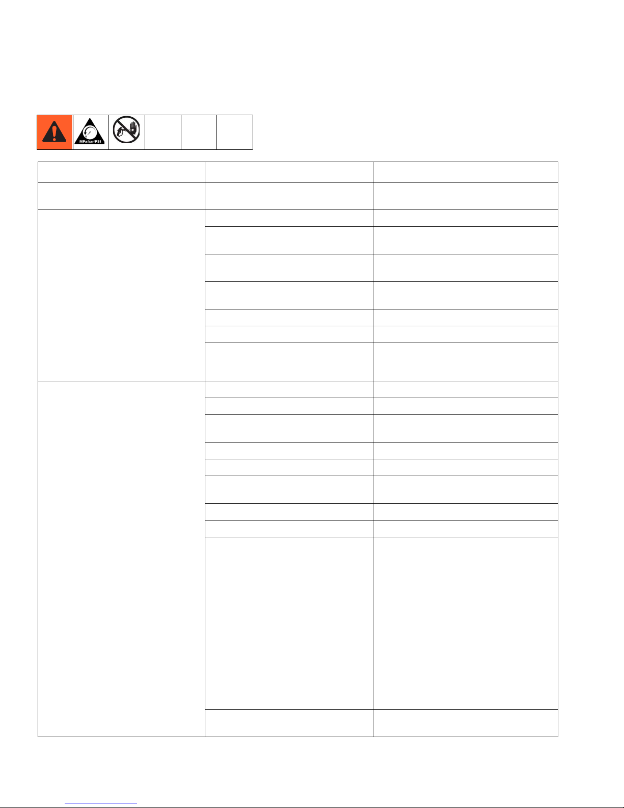
Troubleshooting
Troubleshooting
Problem Cause Solution
E=XX is displayed Fault condition exists Determine fault correction from table, page
20.
Engine won’t start Engine switch is OFF Turn engine switch ON
Engine is out of gas Refill gas tank. Honda Engines Owner’s
Manual.
Engine oil level is low Try to start engine. Replenish oil, if
necessary. Honda Engines Owner’s Manual.
Engine operates, but displacement
pump does not operate
Spark plug cable is disconnected or
damaged
Cold engine Use choke
Fuel shutoff lever is OFF Move lever to ON position
Oil is seeping into combustion chamber Remove spark plug. Pull starter 3 to 4 times.
Error code displayed? Reference pressure control repair. Page 18.
Pump switch is OFF Turn pump switch ON.
Pressure setting is too low Turn pressure adjusting knob clockwise to
Fluid filter (11) is dirty Clean filter. Page 32.
Tip or tip filter is clogged Clean tip or tip filter. See spray gun manual.
Displacement pump piston rod is stuck
due to dried paint
Connecting rod is worn or damaged Replace connecting rod. Page 11.
Drive housing is worn or damaged Replace drive housing. Page 12.
Electrical power is not energizing clutch
field
Clutch is worn, damaged, or incorrectly
positioned
Connect spark plug cable or replace spark
plug
Clean or replace spark plug. Start engine.
Keep sprayer upright to avoid oil seepage.
increase pressure.
Repair pump. See pump manual.
Check wiring connections. Page 16.
Reference pressure control repair. Page 18.
Reference wiring diagram. Page 34.
With pump switch ON and pressure turned to
MAXIMUM, use a test light to check for
power between clutch test points on control
board.
Measure resistance across clutch coil. At 70°
F, the resistance must be between 1.2 0.2
(LineLazer IV 3900/R300); 1.7 0.2
(LineLazer IV 5900); if not, replace pinion
housing.
Have pressure control checked by authorized
Graco dealer.
Replace clutch. Page 13.
8 311020Y

Troubleshooting
Problem Cause Solution
Pinion assembly is worn or damaged Repair or replace pinion assembly. Page 13.
Pump output is low Strainer (34f) is clogged Clean strainer.
Piston ball is not seating Service piston ball. See pump manual.
Piston packings are worn or damaged Replace packings. See pump manual.
O-ring in pump is worn or damaged Replace o-ring. See pump manual.
Intake valve ball is not seating properly Clean intake valve. See pump manual.
Intake valve ball is packed with material Clean intake valve. See pump manual.
Engine speed is too low Increase throttle setting. See operation
manual.
Clutch is worn or damaged Replace clutch. Page 13.
Pressure setting is too low Increase pressure. See operation manual.
Fluid filter (11), tip filter or tip is clogged
or dirty
Large pressure drop in hose with heavy
materials
Excessive paint leakage into throat
packing nut
Fluid is spitting from gun Air in pump or hose Check and tighten all fluid connections.
Pump is difficult to prime Air in pump or hose Check and tighten all fluid connections.
Clutch squeaks each time clutch
engages
High engine speed at no load Misadjusted throttle setting Reset throttle to 3600 engine rpm at no load
Throat packing nut is loose Remove throat packing nut spacer. Tighten
Throat packings are worn or damaged Replace packings. See pump manual.
Displacement rod is worn or damaged Replace rod. See pump manual.
Tip is partially clogged Clear tip. See spray gun manual.
Fluid supply is low or empty Refill fluid supply. Prime pump. See
Intake valve is leaking Clean intake valve. Be sure ball seat is not
Pump packings are worn Replace pump packings. See pump manual.
Paint is too thick Thin the paint according to the supplier’s
Engine speed is too high Decrease throttle setting before priming
Clutch surfaces are not matched to each
other when new and may cause noise
Worn engine governor Replace or service engine governor
Clean filter. See operation or spray gun
manual.
Use larger diameter hose and/or reduce
overall
length of hose. Use of more than 100 ft of 1/4
in. hose significantly reduces performance of
sprayer. Use 3/8 in. hose for optimum
performance (50 ft minimum).
throat packing nut just enough to stop
leakage.
Reprime pump. See operation manual.
operation manual. Check fluid supply often to
prevent running pump dry.
Reduce engine speed and cycle pump as
slowly as possible during priming.
nicked or worn and that ball seats well.
Reassemble
recommendations
pump. See operation manual.
Clutch surfaces need to wear into each other.
Noise will dissipate after a day of run time.
311020Y 9

Troubleshooting
Problem Cause Solution
Gallon counter not working Broken or disconnected wire Check wires and connections. Replace
broken wires.
Bad sensor Replace sensor
Missing magnet Reposition or replace magnet.
Sprayer operates, but display does not Bad connection between control board
and display
Display damaged Replace display
Distance counter not operating properly Trigger sensor not set correctly See “Spray icon does not show on display
Bad wiring connections Check connector, and reconnect
Distance sensor not spaced correctly
from gear
Distance sensor and gear not aligned Remove tire, and press in or pull out gear to
Gear teeth missing or damaged. Replace distance gear/wheel
Wire cracked or broken Replace sensor
Miles not calculating Distance sensor See “Distance counter not operating
Trigger sensor See “Spray icon does not show on display
Gallon counter See “Gallon counter not working”
Bad or damaged control board Replace control board
Fluid spray starts after spray icon is
shown on display
Fluid spray starts before spray icon is
shown on display
Spray icon does not show on display
when fluid is sprayed
Interrupter (164) is improperly positioned Turn screw (126) counterclockwise until
Interrupter (164) is improperly positioned Turn screw (126) clockwise until spray icon is
Loose connector Check connector and reconnect
Interrupter (164) is improperly positioned Turn screw (126) counterclockwise until
Reed switch assembly (166) is damaged Replace reed switch assembly (166)
Magnet on assembly (166) is missing Replace reed switch assembly (166)
Cut or sliced wire Replace distance sensor harness (66)
Control board is damaged Replace control board
Display is damaged Replace display
Interrupter (164) is improperly positioned Turn screw (126) clockwise until spray icon is
Reed switch assembly (166) is damaged Replace reed switch assembly (166)
Remove display and reconnect
when fluid is sprayed”
Adjust space between sensor and gear to
.050 --/+ .020 in. See page 19.
align sensor and gear.
properly”
when fluid is sprayed”
spray icon synchronizes with fluid spray
synchronized with fluid spray
spray icon synchronizes with fluid spray
synchronized with fluid spray
10 311020Y
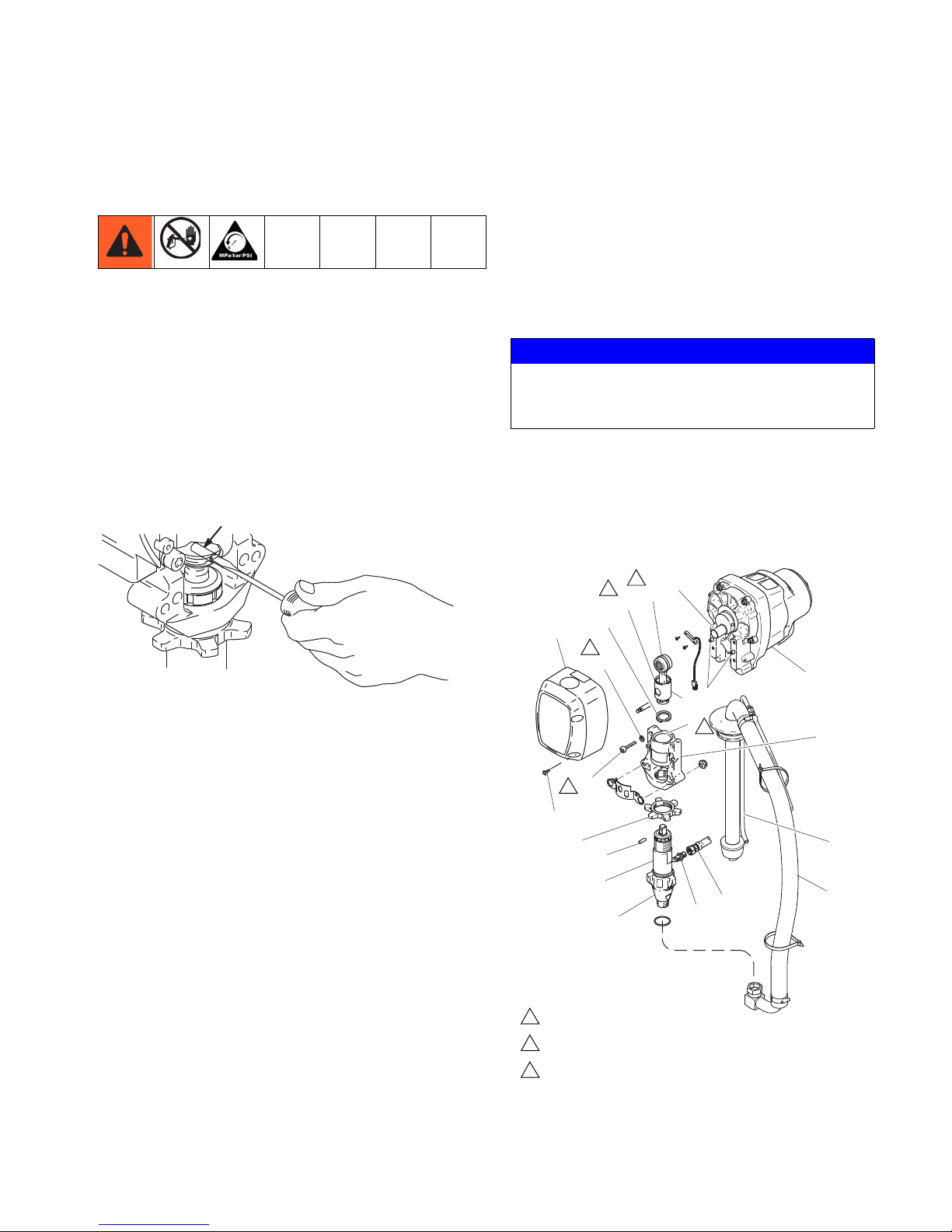
Bearing Housing and Connecting Rod
7675B
235
Fig. 1
ti25624a
83
236
D
E
B
24
F
26
C
173
187
183
84
235
21
A
60
100
34
34g
22
Oil
Pack with bearing grease 114819
LineLazer IV 3900/R300: Torque to
200 in-lb (22.6 N·m) LineLazer V
5900: Torque to 25 ft-lb
Model 248862 shown
1
2
3
Fig. 2
1
2
2
3
3
Bearing Housing and Connecting Rod
Removal
1 Relieve pressure, page 7.
2 Fig. 2. Remove screws (187) and front cover (83).
3 Unscrew suction tub (34) from pump, hold wrench
on pump intake valve (A) to keep pump from
loosening.
4 Disconnect pump outlet hose (100) from
displacement pump outlet nipple (60).
5 Fig. 1. Use screwdriver to push up retaining spring
(236) at top of pump. Push out pin (235).
3 Clean mating surfaces of bearing and drive
housings.
4 Align connecting rod with crank (B) and carefully
align locating pins (F) in driving housing (24) with
holes in bearing housing (22). Push bearing housing
onto drive housing or tap into place with plastic
mallet.
NOTICE
To prevent damage to soft key buttons, do not
press the buttons with sharp objects such as pens,
plastic cards, or fingernails.
5 Install screws (183) and lock-washers (173) on
bearing housing. Torque evenly, referencing note 3
value in Fig. 2.
6 Install pump. Refer to Displacement Pump,
Installation, page 21.
remove displacement pump(21).
from bearing housing (22).
6 Fig. 2. Loosen retaining nut (84). Unscrew and
7 Remove four screws (183) and lock-washers (173)
8 Pull connecting rod (26) and lightly tap lower rear of
bearing housing (22) with plastic mallet to loosen
from drive housing (24). Pull bearing housing and
connecting rod assembly (26) off drive housing.
9 Inspect crank (B) for excessive wear and replace
parts as needed.
Installation
1 Evenly lubricate inside of bronze bearing (C) in
bearing housing (22) with high-quality motor oil.
Liberally pack top roller bearing (E), lower bearing
(D) inside connecting rod assembly (26) with
bearing grease.
2 Assemble connecting rod (26) and bearing housing
(22).
311020Y 11
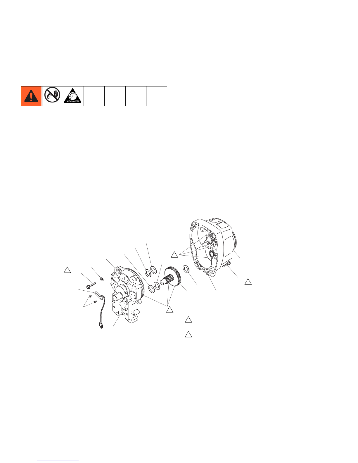
Drive Housing
ti6396a
25
189
A
178
23
179
24h
24g
178
24
173
189
182
158
181
Fig. 3
LineLazer IV 3900/R300: Torque to 200 in-lb (22.6 N·m)
LineLazer IV 5900: Torque to 25 ft-lb (34 N·m)
Apply remaining grease to these areas
1
2
1
2
2
1
Drive Housing
Removal
1 Relieve pressure, page 7.
2 Fig. 3. Remove bearing housing. Refer to Bearing
Housing and Connecting Rod procedure on page
11.
3 Remove two screws (158) and reed switch (182).
4 Remove six screws (189) and reed switch (25).
5 Lightly tap around drive housing (24) to loosen drive
housing. Pull drive housing straight off pinion
housing. Be prepared to support gear cluster (23),
which may also come out.
Installation
1 Liberally apply bearing grease (supplied with
replacement gear cluster) to gear cluster (23) and to
areas called out by reference 2 in Fig. 3.
2 Place bronze colored washer (24g) on shaft
protruding from large shaft of drive housing (24).
Place silver colored washer (24h) on pinion
housing. Clean mating surfaces of pinion and drive
housings. Align gears and push new drive housing
straight onto pinion housing and locating pins (A).
3 Install six screws (189). Torque evenly, referencing
note 1 value in Fig. 3.
4 Install reed switch (182) with two screws (158).
5 Install bearing housings. Do steps 1 through 6 of
Bearing Housing and Connecting Rod
procedures on page 11.
12 311020Y
 Loading...