

Page 1
INSTRUCTIONS--REPAIR
308874
KEEP FOR REFERENCE.
Read this and all related manuals for
important warnings and instructions.
INSTRUCTIONS
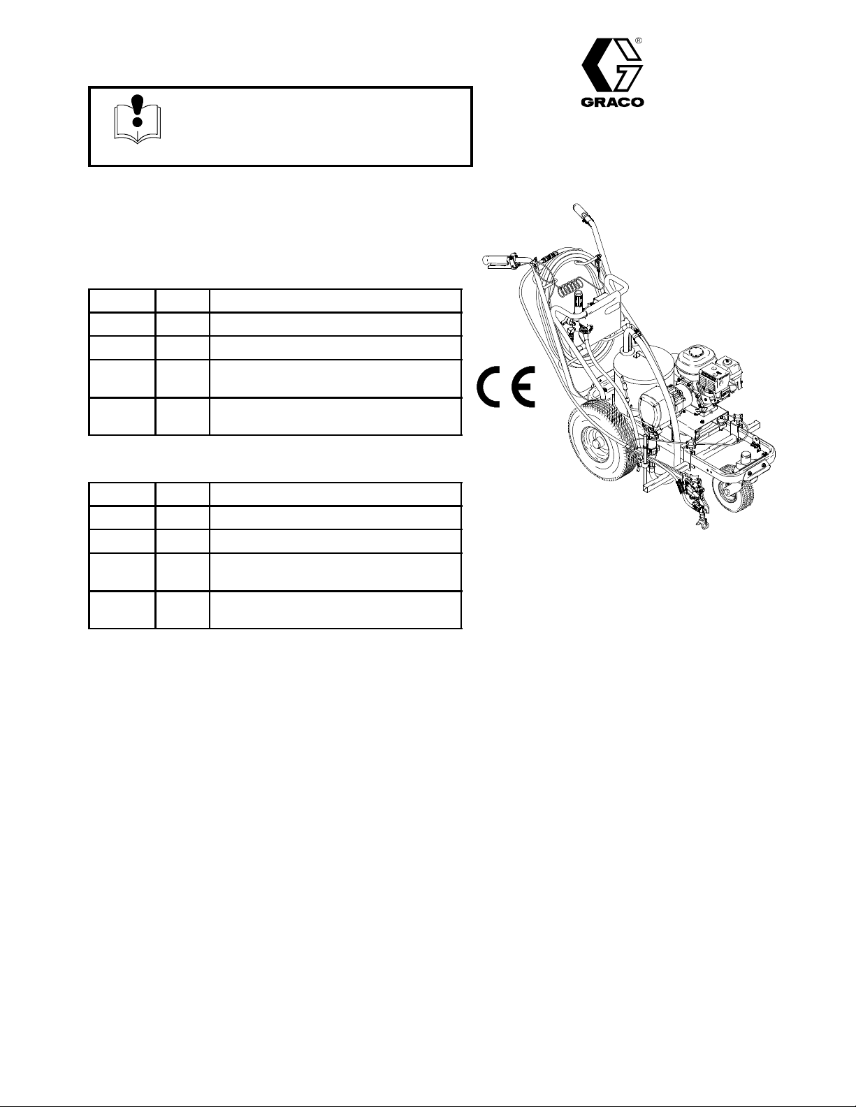
LineLazer II 3900 and 5900
3300 psi (230 bar, 23 MPa ) Maximum Working Pressure
LineLazer II 3900
Model Series Description
232651 A Complete Sprayer
232652 A Complete Sprayer with 2nd Gun Kit
23301 1 A Complete Sprayer with Gauge and
Pail Kit
233012 A Complete Sprayer with 2nd Gun Kit,
Gauge and Pail Kit
LineLazer II 5900
Model Series Description
232661 A Complete Sprayer
232662 A Complete Sprayer with 2nd Gun Kit
233013 A Complete Sprayer with Gauge and
Pail Kit
233014 A Complete Sprayer with 2nd Gun Kit,
Gauge and Pail Kit
Rev. P
First choice when
quality counts.t
Model 232651
All models are not available in all countries
PATENTS PENDING
8824A
Related Manuals
Operation 308873..........................
Displacement Pump 308798.................
Spray Gun 308235.........................
Spray Tip *.................................
PC Board 308919..........................
Drain Valve Kit 308961......................
* for spray tip selection see page 4.
EN
Table of Contents
Component Identification and Function 3............
Spray Tip Selection Guide 4.......................
Maintenance 5...................................
Troubleshooting 6................................
Repair
Bearing Housing & Connecting Rod 8.............
Drive Housing 9................................
Pinion Assembly/Rotor/Field/Shaft/Clutch 10.......
Clamp 1 1.....................................
Clutch Housing 12..............................
Engine 12.....................................
Pressure Control 14............................
Displacement Pump 16.........................
Parts
Model 232651, 232661 LineLazer II 17............
Pinion Assembly 25............................
Complete Sprayers 28..........................
Pressure Control 27............................
Dimensions 29...................................
Technical Data 29................................
Graco Warranty 29...............................
Graco Phone Number 29..........................
Page 2
Warnings and Cautions
Warning Symbol
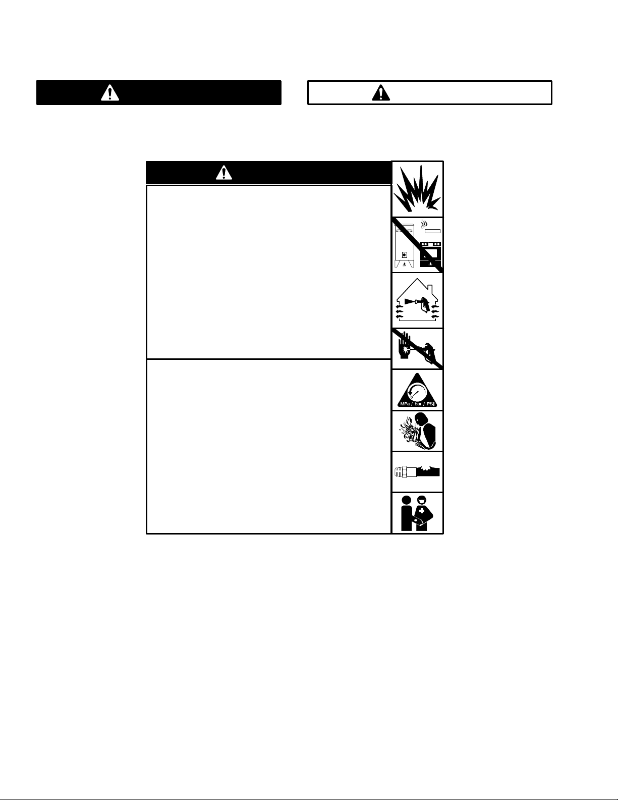
WARNING
This symbol alerts you to the possibility of serious
injury or death if you do not follow the instructions.
WARNING
Fire and explosion can occur when spraying or flushing flammable
fluid in an area where air circulation is poor and flammable vapors
can be ignited by an open flame or sparks.
To help prevent a fire and explosion:
DUse outdoors or in an extremely well ventilated area.
DDo not use 1,1,1- -trichloroethane, methylene chloride, other
halogenated hydrocarbon solvents or fluids containing such
solvents in pressurized aluminum equipment. Such use could
result in a chemical reaction, with the possibility of explosion.
DRemove, extinguish or unplug all ignition sources;
tape wall switch. Do not smoke in spray area.
DNever fill fuel tank while the engine is running or hot.
DGround Sprayer, object being sprayed, paint and solvent pails.
DHold gun firmly to side of a grounded pail when triggering into pail.
DUse only conductive airless paint hose.
DNever run engine in inclosed area.
DDo not flush with gasoline.
Caution Symbol
CAUTION
This symbol alerts you to the possibility of damage to
or destruction of equipment if you do not follow the
instructions.
Fluid injection is a serious injury! If high pressure fluid pierces
your skin, the injury might look like “just a cut”. But it is a serious
wound! Get immediate surgical treatment.
To help prevent injection, always:
DEngage trigger safety latch when not spraying.
DPoint gun away from yourself or anyone else.
DRelieve pressure before checking or repairing any leak.
DRelieve pressure when you turn off the sprayer or stop spraying.
DDo not use components rated less than system Maximum
Working Pressure
DWhen flushing, ground equipment to grounded object with orange
wire clamp.
DDo not flush equipment on asphalt or other non--conductive
surfaces.
Never allow children to use this unit. If you are injured using this
equipment, get immediate medical treatment.
3088742
Page 3
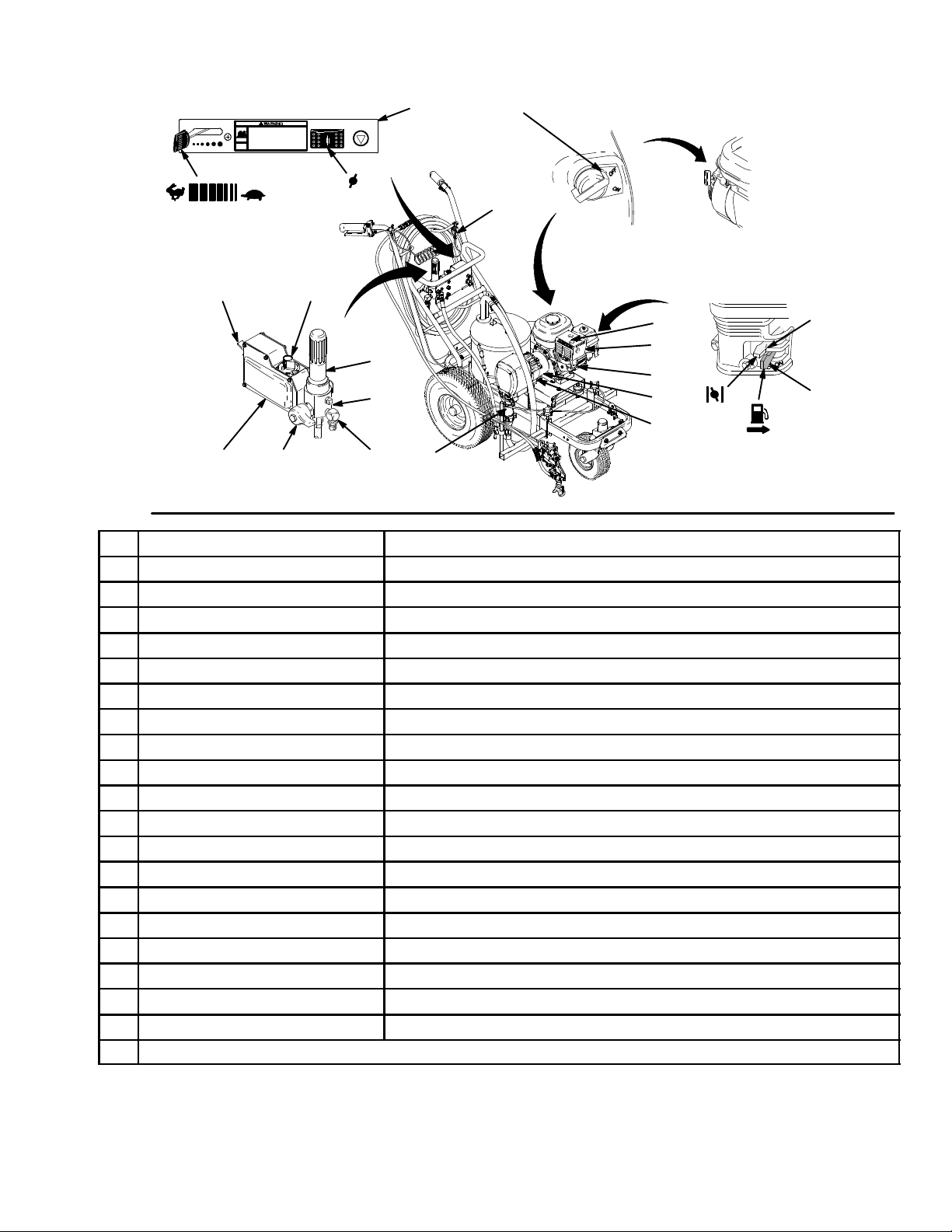
Component Identification and Function
Model 232651
ENGINE SPEED
TIP SIZE
ENGINE STOP
J
K
V
AB
C
H
F
U
P
L
R
G
S
M
W
N
T
Fig. 1
A Pressure Control Switch ON/OFF, enables/disables clutch function
B Pressure Adjusting Knob Controls fluid outlet pressure
C Air Cleaner* Filters air entering the carburetor
D Fuel Tank* Uses 86 octane gasoline
E Muffler* Reduces noise of internal combustion
F Spark Plug Cable* Routes electrical current to spark plug
G Fuel Shutoff Lever* On/off lever to regulate fuel flow from gasoline tank to carburetor
H Choke* Enriches air/gasoline mixture for cold starting
J Throttle Lever* Adjusts engine speed for large or small orifice spray tips
K Engine Switch* Enables/disables engine operation
L Secondary Fluid Outlet Second hose and spray gun is connected here
M Pressure Control Controls clutch cycling to maintain fluid pressure
N Primary Fluid Outlet Hose and spray gun is connected here
P Engine* 4--cycle gasoline engine
R Clutch Housing Transfers power from engine to drive assembly
S Drive Housing Transfers power from clutch to displacement pump
T Displacement Pump Provides fluid to be sprayed through spray gun
U Fluid Filter Filters fluid between source and spray gun
V Grounding Clamp and Wire Grounds sprayer system
W Pressure Drain Valve Relieves fluid pressure when open
* For more detailed explanations of these controls, refer to the Honda Engines Owner’s Manual; supplied
8825A
Install the spray tip in the gun. Sprayer is supplied with tip LLT319. For additional applications, use the Tip
Selection T able on page 4.
308874 3
Page 4

Spray Tip Selection Table
LineLazer Tip Selection Guide. Sprayer is supplied with tip LL5319. For additional applications, use the tip
selection table as follows:
Note: the last three digits (LL5319
For example: the line width for tip LL5319 is 4 in. as shown in the table below . The tip orifice for tip LL5319
LineLazer Tip Selection Table
Tip Size
28621 1* 2 inches Sport court -- light film build
LL5213* 2 inches Sport court -- heavy film build
LL5215* 4 inches Alkyd paints only -- light film build
LL5217 4 inches Alkyd paints only -- medium film build
LL5219 4 inches Alkyd paints only -- heavy film build
LL5315 4 inches Most traffic paints -- light film build
LL5317 4 inches Most traffic paints -- medium film build
LL5319 4 inches Most traffic paints -- medium film build
LL5321 4 inches Most traffic paints -- heavy film build
LL5323 4 inches Most traffic paints -- heavy film build
LL5417# 4 -- 8 inches All paints and high solids traffic paints -- light film build
LL5419# 4 -- 8 inches All paints and high solids traffic paints -- medium film build
LL5421# 4 -- 8 inches All paints and high solids traffic paints -- heavy film build
LL5621 8 -- 12 inches All traffic paints -- light film build
LL5623 8 -- 12 inches All traffic paints -- medium film build
LL5625 8 -- 12 inches All traffic paints -- medium film build
LL5627 8 -- 12 inches All traffic paints -- heavy film build
Line Width Used For
) of the tip part number identifies the line width and tip orifice (opening) in millimeters.
is 19 mm.
* May require 100 mesh filter to minimize tip plugging.
# Best for cold weather applications.
How to Maximize Line Quality and Reduce Tip Wear. Observe the following suggestions to increase line quality
and minimize sprayer tip wear.
1. Select a larger tip orifice and run the sprayer at a reduced operating pressure.
2. Running larger tip sizes (example: use tip LL5321 @ 2000 psi instead of LL5317 @ 3300 psi) will significantly
increase tip life and reduce tip plugging. It will also produce a more uniform film build across the line.
3088744
Page 5
Maintenance
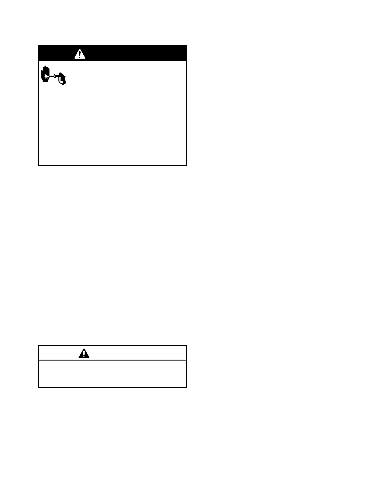
WARNING
INJECTION HAZARD
The system pressure must be manually
relieved to prevent the system from
starting or spraying accidentally. Fluid
under high pressure can be injected through the
skin and cause serious injury. To reduce the risk of
an injury from injection, splashing fluid, or moving
parts, follow the Pressure Relief Procedure
whenever you:
D are instructed to relieve the pressure,
D stop spraying,
D check or service any of the system equipment,
D or install or clean the spray tip.
DAILY: Check and fill the gas tank.
AFTER THE FIRST 20 HOURS OF OPERATION:
Drain the oil and refill with clean oil.
WEEKLY: Remove air filter cover and clean element.
Replace element, if necessary. If operating in an
unusually dusty environment: check filter daily and
replace, if necessary.
Replacement elements can be purchased from your
local HONDA dealer.
WEEKLY: Check level of TSL in displacement pump
packing nut. Fill nut, if necessary. Keep TSL in nut to
help prevent fluid buildup on piston rod and premature
wear of packings.
Pressure Relief Procedure
1. Lock gun trigger safety.
2. Turn engine ON/OFF switch to OFF.
3. Move pressure control switch to OFF and turn
pressure control knob fully counterclockwise.
4. Unlock trigger safety. Hold metal part of gun firmly
to side of grounded metal pail, and trigger gun to
relieve pressure.
5. Lock gun trigger safety.
6. Open pressure drain valve. Leave valve open until
ready to spray again.
7. Disconnect spark plug cable.
If you suspect that the spray tip or hose is completely
clogged, or that pressure has not been fully relieved
after following the steps above, VERY SLOWLY
loosen tip guard retaining nut or hose end coupling to
relieve pressure gradually, then loosen completely.
Now clear tip or hose.
CAUTION
For detailed engine maintenance and specifications,
refer to separate Honda Engines Owner’s Manual,
supplied.
AFTER EACH 100 HOURS OF OPERA TION:
Change oil.
MONTHLY: Oil connecting rod.
SPARK PLUG: Use only BPR6ES (NGK) or
W20EPR--U (NIPPONDENSO) plug. Gap plug to
0.028 to 0.031 in. (0.7 to 0.8 mm). Use spark plug
wrench when installing and removing plug.
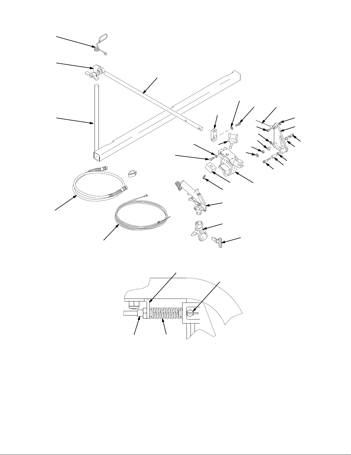
Caster Wheel
(See letter call-outs in Parts drawing on page 21)
1. Once each year, tighten nut (A) until spring washer
bottoms out. Then back off the nut 1/2 to 3/4 turn.
2. Once each year, tighten nut (B) until it begins to
compress spring washer. Then tighten the nut an
additional 1/4 turn.
3. Once each month, grease the wheel bearing (F).
4. Check pin (C) for wear. If pin is worn out, there
will be play in the caster wheel. Reverse or
replace the pin as needed.
5. Check caster wheel alignment as necessary.
To align: loosen bolt (D), align wheel and tighten
bolt (D).
DAILY: Check engine oil level and fill as necessary.
DAILY: Check hose for wear and damage.
DAILY: Check gun safety for proper operation.
DAILY: Check pressure drain valve for proper
operation.
308874 5
Page 6
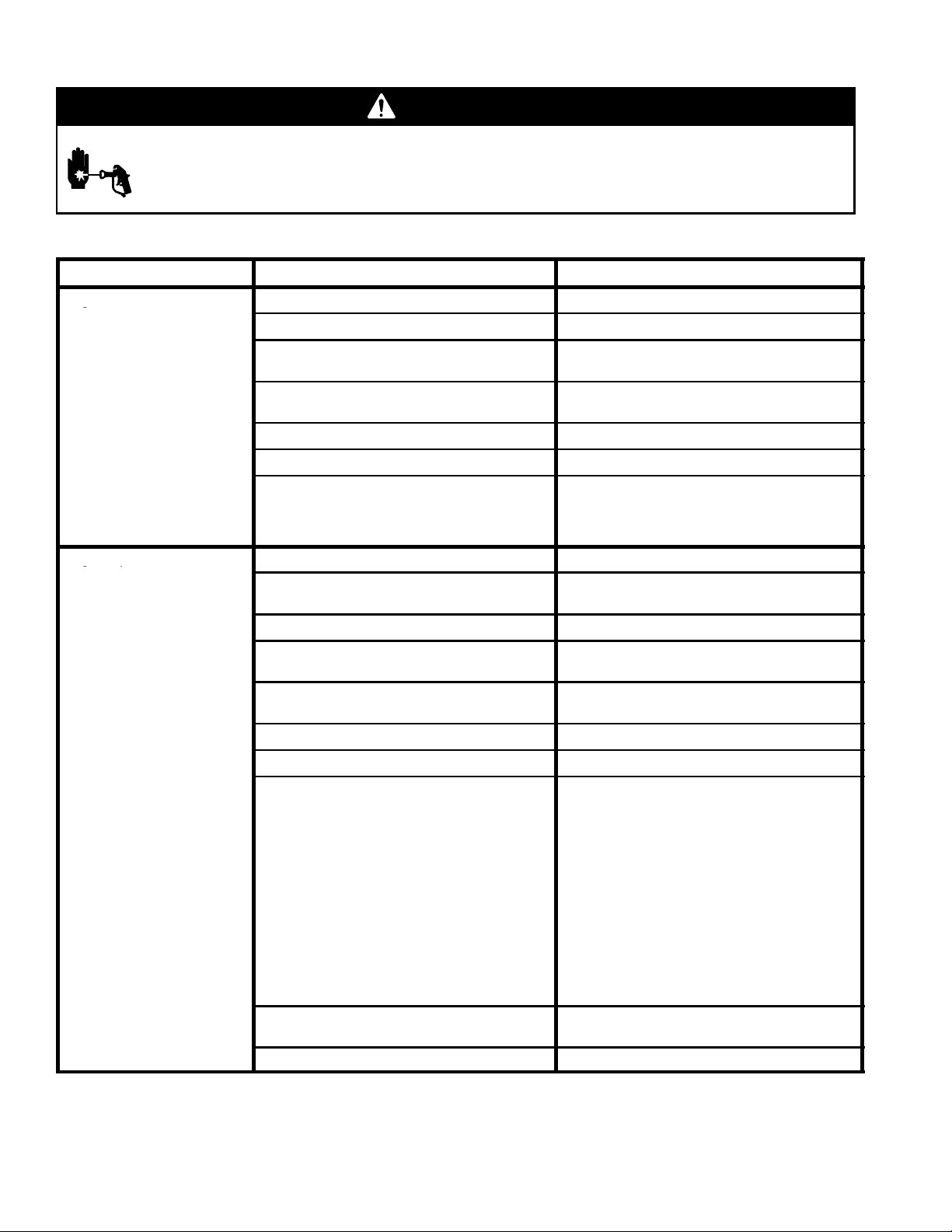
Troubleshooting
g
g
p
WARNING
INJECTION HAZARD
To reduce risk of serious injury, including fluid injection or splashing in eyes or on skin, or injury from
moving parts, always follow Pressure Relief Procedure Warning, page 5, before checking, adjusting, cleaning or shutting down sprayer. Disconnect spark plug!
Check everything in chart before disassembling sprayer.
PROBLEM
Engine won’t start
Engine operates, but displacement pump does not
operate.
CAUSE SOLUTION
Engine switch is OFF Turn engine switch ON
Engine is out of gas Refill gas tank. Honda Engines Owner’s Manual.
Engine oil level is low Tryto start engine. Replenish oil, if necessary.
Spark plug c able is disconnected or damaged Connect spark plug cable or replace spark
Cold engine Use choke
Fuel shutoff lever is OFF Move lever to ON position
Oil is seeping into combustion chamber Remove spark plug. Pull starter rope 3 or 4
Pressure control switch is OFF. Turn pressure control switch ON.
Pressure setting is too low. Turn pressure adjusting knob clockwise to
Fluid filter(318)is dirty. Clean filter. See page 27.
Tip or tip filter is clogged. Cleantip or tip filter. See gun instruction
Displacementpump piston rod is stuck due to
dried paint.
Honda Engines Owner’s Manual.
plug
times.Clean or replace spark plug. Try to start
engine. Keep sprayer uprightto avoid oil seepage.
increase pressure.
manual.
Repair pump. See manual 308798.
Connecting rod is worn or damaged. Replace connecting rod. See page 8.
Drive housing is worn or damaged. Replace drive housing. See page 9.
Electrical power is not energizing field. Check wiringconnections.See page 12.
Reference control board diagnostics. Page 15.
With pressure control switch ON and pressure
turned to MAXIMUM, use a test lightto check
for power between clutch terminals on control
board.
Remove black clutch wires from control board
and measure resistance across wires. At 70_
F, the resistance must be between 1.2 ¦ 0.2
(LL 3900); 1.7 ¦ 0.2 (LL 5900); if not, replace
pinion housing.
Have pressure control checked by authorized
Graco dealer.
Clutch is worn, damaged, or incorrectly
positioned.
Pinion assembly is worn or damaged. Repair or replace pinion assembly, see pg 10.
Replace clutch. See page 10.
3088746
Page 7
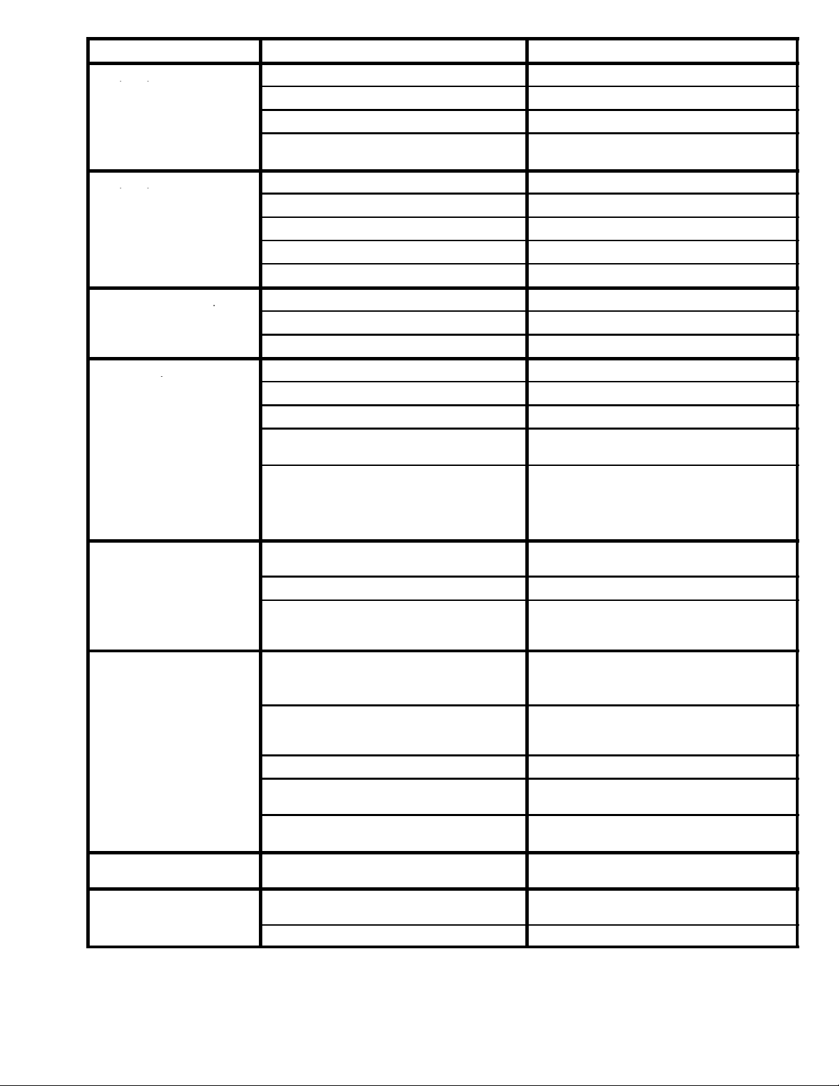
PROBLEM
p
p
p
p
p
y
CAUSE SOLUTION
Pump output is low on
upstroke.
Pump output is low on downstroke or on both strokes.
Paint leaks into wetcup.
Fluid delivery is low.
Hose inlet screen (27) is clogged. Clean inlet screen.
Piston ball (25) is not seating. Servicepiston ball. See manual 308798.
Piston packings are worn or damaged. Replacepackings. See manual 308798.
O-ring(17) in displacement pump is worn or
damaged.
Hose strainer (27) is clogged. Clean strainerscreen.
Piston packings are worn or damaged. Replacepackings. See manual 308798.
Intake valve ball is not seating properly. Clean intake valve. See manual 308798.
Engine speed is too low. Increase throttlesetting.See manual 308873.
Clutch is worn or damaged. Replace clutch. See page 10.
Wetcup is loose. Tightenwetcup just enough to stop leakage.
Throat packings are worn or damaged. Replace packings. See manual 308798.
Displacementrod is worn or damaged. Replace rod. See manual 308798.
Inletscreen is clogged. Clean inletscreen.
Pressure setting is too low. Increase pressure. See manual 308873.
Engine speed is too low. Increase throttlesetting.See manual 308873.
Fluid filter(318),tipfilter or tip is clogged or
dirty.
Replace o-ring. See manual 308798.
Clean filter. See manual 308873. Or,see gun
instruction manual.
Fluid is spitting from gun.
Pump is difficult to prime.
Clutch squeaks each time
clutch engages.
Large pressure drop in hose withheavy
materials.
Air in pump or hose. Check and tighten all fluid connections.
Tip is partially clogged. Clear tip. See gun instructionmanual.
Fluid supply is low or empty. Refill fluid supply.Prime pump. See manual
Air in pump or hose. Check and tighten all fluid connections.
Intake valve is leaking. Clean intake valve. Be sure ball seat is not
Pump packings are worn. Replace pump packings. See manual 308798.
Paint is too thick. Thin the paint according to the supplier’s
Engine speed is too high. Decrease throttle setting before priming pump.
Small irregularitiesof new clutch surfaces
grind together and cause noise
Use larger diameter hose and/or reduce overall
length of hose. Use of more than 100 ft of 1/4
in. hose significantly reduces performance of
sprayer. Use 3/8 in. hose for optimum performance (50 ft minimum).
Reprime pump. See manual 308873.
308873. Check fluidsupply often to prevent
running pump dry.
Reduce engine speed and cycle pump as
slowly as possible during priming.
nicked or worn and that ballseats well. Reassemble valve.
recommendations.
See manual 308873.
Clutch surfaces need to wear into each other.
Noise will dissipate after a day of run time.
High engine speed at no
load.
Misadjustedthrottle setting. Reset throttle to 3600--3800 engine rpm at no
load.
Worn engine governor. Replace or service engine governor.
308874 7
Page 8
Bearing Housing and Connecting Rod
NOTE: The item numbers referenced are for the
Hi-Boy models. The Lo-Boy models may have different
item numbers. Use the Hi-Boy item number and part to
find the corresponding Lo-Boy part and item number.
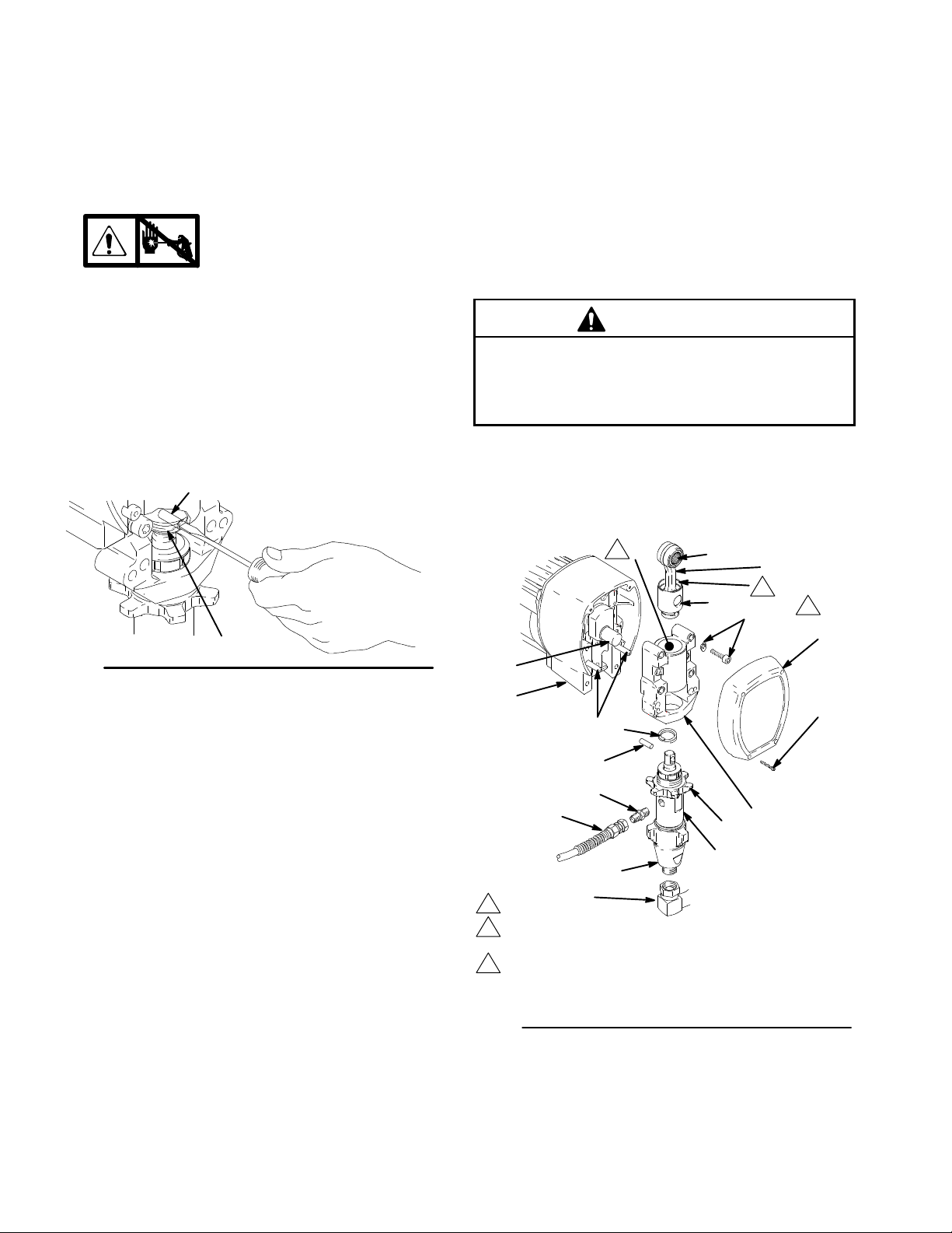
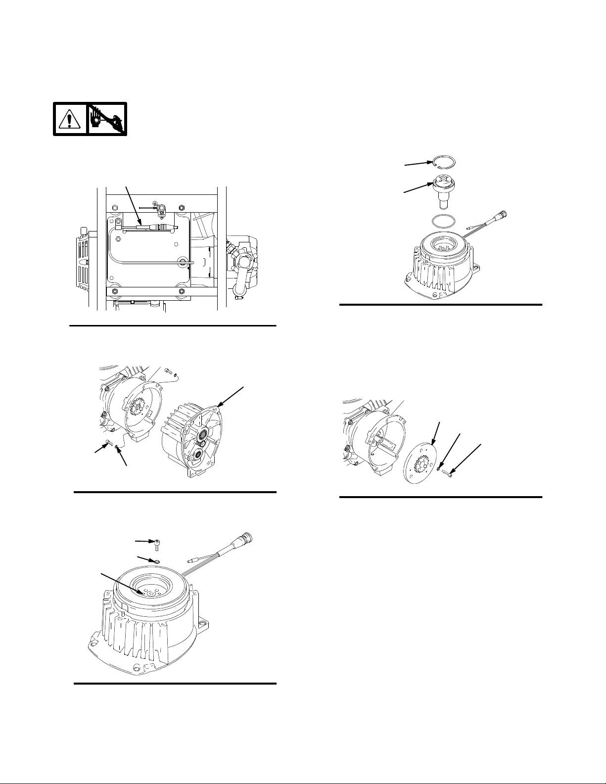
Removal
1.
2. Fig. 3. Remove screws (29) and front cover (86).
3. Unscrew suction tube (27) from pump, hold
wrench on pump intake valve (A) to keep pump
from loosening.
4. Disconnect pump outlet hose (25) from
displacement pump outlet nipple (107).
5. Fig. 2. Use screwdriver to push up retaining spring
(83) at top of pump. Push out pin (82).
Fig. 2
6. Fig. 3. Loosen jam nut (81). Unscrew and remove
displacement pump.
7. Remove four screws (31) and lockwashers (32)
from bearing housing (84).
8. Pull connecting rod (85) and lightly tap lower rear
of bearing housing (84) with plastic mallet to
loosen from drive housing (87). Pull bearing
housing and connecting rod assembly (85) off
drive housing.
9. Inspect crank (B) for excessive wear and replace
parts as needed.
Installation
10. Evenly lubricate inside of bronze bearing (C) in
bearing housing (84), and inside of connecting rod
link (D), with high-quality motor oil (do not use
grease). Liberally pack roller bearing (E) in
connecting rod assembly (85) with bearing grease.
Relieve pressure; page 5.
82
83
7675B
1 1. Assemble connecting rod (85) and bearing housing
(84).
12. Clean mating surfaces of bearing and drive
housings.
13. Align connecting rod with crank (B) and carefully
align locating pins (F) in drive housing (87) with
holes in bearing housing (84). Push bearing
housing onto drive housing or tap into place with
plastic mallet.
CAUTION
DO NOT use bearing housing screws (31) to align
or seat bearing housing with drive housing. Align
these parts with locating pins (F), to avoid premature bearing wear.
14. Install screws (31) and lockwashers (32) on
bearing housing. Tighten evenly to 175 in-lb (19
N¡m).
15. Refer to Displacement Pump, Installation, page 16.
1
C
B
87
83
F
82
107
25
A
1
Oil
2
Pack with bearing grease 114819
3
LL 3900: T orque to 200 in-lb (22.6 N¡m)
LL 5900: T orque to 25 ft-lb (34 N¡m)
Fig. 3
27
Model 232651 shown
E
85
80
81
D
2
31,32
84
3
86
29
8796A
3088748
Page 9
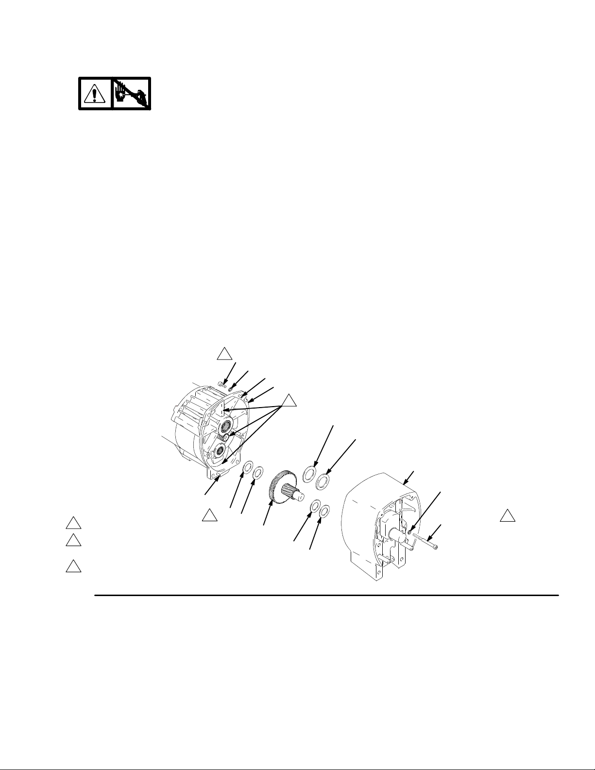
Drive Housing
Removal
1.
Relieve pressure; page 5.
2. Fig. 4. Remove bearing housing. Do 1. through 8.
of Bearing Housing and Connecting Rod
procedure on page 8.
3. Remove two screws (51) and lockwashers (50).
4. Remove four screws (120) and lockwashers (119)
from pinion housing (88a).
5. Lightly tap around drive housing (87c) to loosen
drive housing. Pull drive housing straight off pinion
housing. Be prepared to support gear cluster (78),
which may also come out.
Installation
1. Liberally apply bearing grease (supplied with
replacement gear cluster) to gear cluster (78). and
to areas called out by note 3. Use full 0.62 pint
(0.29 liter) of grease for LL 3900 and 0.68 pint
(0.32 liter) of grease for LL 5900.
2. Place bronze colored washer (87g) on shaft
protruding from large shaft of drive housing(87c).
Note: If replacing a washer with pin holes with a
washer without pin holes, remove guide pins from
housing. Place silver colored washer (87h) on pins
on pinion housing. Align gears and push new drive
housing straight onto pinion housing and locating
pins (B).
3. Install four screws (120) and lockwashers (119)
into pinion housing (88a).
4. Install two screws (5) and lockwashers (50).
5. Fig. 3. Install bearing housing. Do 10. through 15.
of Bearing Housing and Connecting Rod
procedure on page 8.
B
1
LL 3900 only
2
Torque to 125 in-lb -- LL 3900
Torque to 200 in-lb -- LL 5900
3
Apply remaining grease to these areas
Fig. 4
2
120
119
B
88a
3
87h
87g
87c
50 (LL 3900)
51 (LL 5900)
79
1
79
51 (LL 3900)
52 (LL 5900)
2
78
77
79
TI0178A
308874 9
Page 10
Pinion Assembly/Rotor/Field/Shaft/Clutch
X
Removal
Fig. 6. If pinion assembly (88a) is attached to clutch
housing (92), do 1. through 4. Otherwise, start at 5.
1.
Relieve pressure; page 5.
2. Fig. 5. Disconnect field cable (X) from pressure
control.
5. Remove four screws (52) and lockwashers (50).
Install two screws in threaded holes (E) in rotor.
Alternately tighten screws until rotor comes off.
6. Fig. 8. Remove retaining ring (Z).
7. Tap pinion shaft (A) out with plastic mallet.
Z
A
Fig. 5
8837A
3. Fig. 6. Remove five screws (89/96) and
lockwashers (50/51) and pinion assembly (88a).
88a
89 (LL 3900)
96 (LL 5900)
Fig. 6
50 (LL 3900)
51 (LL 5900)
8700A
4. Fig. 7. Place pinion assembly (88a) on bench with
rotor side up.
52
50
E
Fig. 8
8703A
8. Fig.9. Use an impact wrench or wedge something
between clutch and clutch housing to hold clutch
during removal.
9. Remove four screws (50) and lockwashers (53).
10. Remove clutch (91).
91
53
50
Fig. 9
8704A
Fig. 7
8701A
30887410
Page 11

Pinion Assembly/Rotor/Field/Shaft/Clutch
Installation
1. Fig. 10. Lay two stacks of two dimes on smooth
bench surface.
5. Install four screws (53) and lockwashers (50) with
torque of 125 in-lb.
2. Lay armature (91) on two stacks of dimes.
3. Press center of clutch down on bench surface.
91
0.12 .01 in. (3.0 .25 mm)
Fig. 10
4. Install armature (91) on engine drive shaft.
Removal
1. Fig. 11. Loosen two screws (53) on clamp (94).
2. Push screwdriver into slot in clamp (94) and
remove clamp.
Installation
1. Fig. 11. Install engine shaft key (95).
6. Fig. 8. Tap pinion shaft (A) in with plastic mallet.
7. Install retaining ring (Z).
8. Fig. 7. Place pinion assembly on bench with rotor
9. Apply locktite to screws. Install four screws (53)
8705A
10. Install pinion assembly (88a) with five screws (89)
1 1. Fig. 5. Connect field cable (X) to pressure control.
Clamp
1
2
3
side up.
and lockwashers (50). Alternately torque screws
to 125 in-lb until rotor is secure.
and lockwashers (50).
Face of clutch housing
1.550 .010 in. (39.37 .25 mm); LL 3900
1.812 .010 in. (46.02 .25 mm); LL 5900
Torque to 125 .10 in-lb (14 1.1 N¡m)
92
1
2. Tap clamp (94) on engine shaft A. Maintain
dimension shown note 2 Fig. 11.
3. Press clamp (94) onto engine shaft (A). Maintain
dimension shown note 2 in Fig. 11.
Check dimension: Place rigid, straight steel bar (B)
across face of clutch housing (5). Use accurate
measuring device to measure distance between
bar and face of clamp. Adjust clamp as necessary.
Torque two screws (16) to 125 10 in-lb (14 1.1
N¡m).
95
Fig. 11
2
94
B
53
3
A
03483
308874 11
Page 12
Clutch Housing
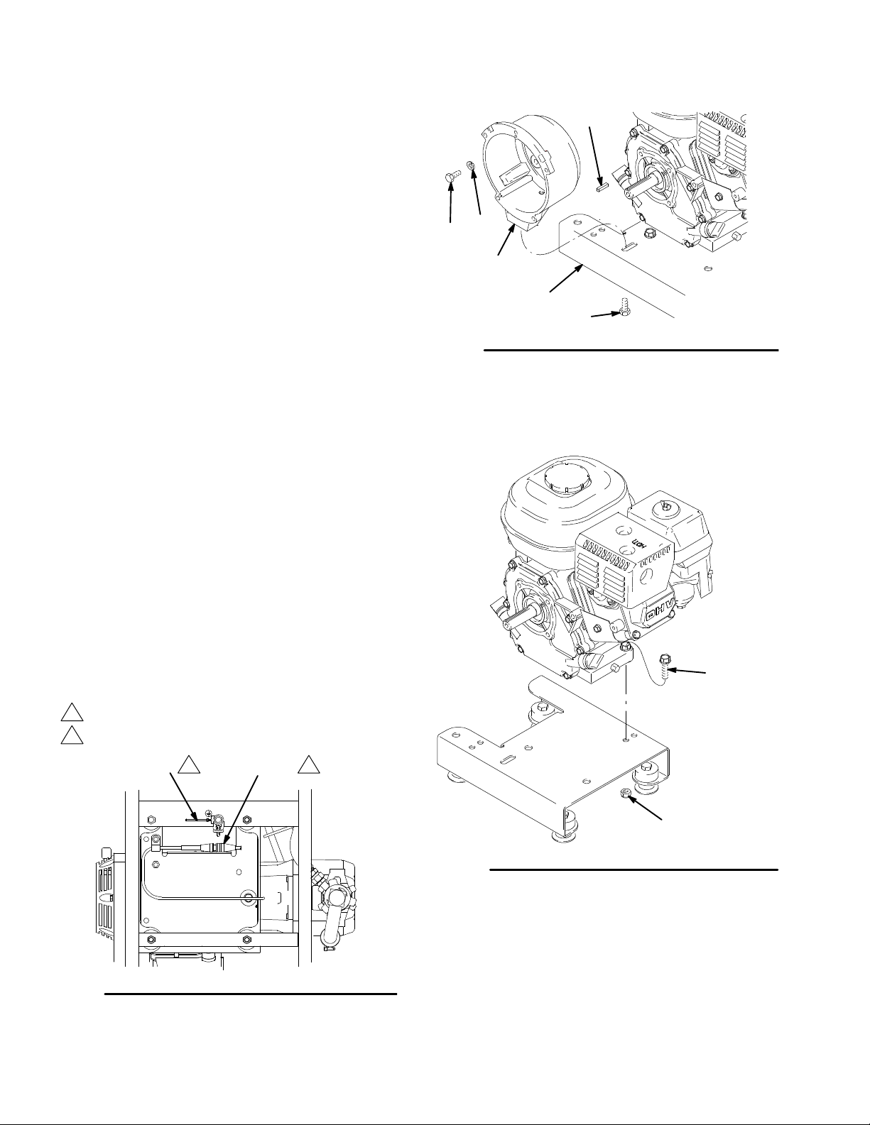
Removal
1. Fig. 12. Remove four capscrews (98) and
lockwashers (99) which hold clutch housing (92) to
engine.
2. Remove cap screw (96), lockwasher (50), and
washer (97) from beneath mounting plate (D).
95
3. Remove engine key (95).
4. Pull off clutch housing (92).
Installation
1. Fig. 12. Push on clutch housing (92).
2. Install cap screw (96), lockwasher (50), and
washer (97) from beneath mounting plate (D).
3. Install four capscrews (98) and lockwashers (99)
and secure clutch housing (92) to engine.
Engine
Removal
1. Remove Pinion
Assembly/Rotor/Field/Pinion/Clutch, Clamp
and Clutch Housing, as instructed on pages 7, 10
and 11.
2. Fig. 13. Disconnect all necessary wiring.
3. Fig. 14. Remove two locknuts (55) and screws
(54) from base of engine.
4. Lift engine carefully and place on work bench.
98
Fig. 12
99
92
D
50,96,97
8826A
NOTE: All service to the engine must be performed by
an authorized HONDA dealer.
1
To the field
2
To frame (LL 3900), to engine (LL 5900)
Green
Fig. 13
30887412
62 Ref
12
8837A
54
55
Fig. 14
Installation
1. Lift engine carefully and place on cart.
2. Fig. 14. Install two screws (54) in base of engine
and secure with locknuts (55).
3. Fig. 13. Connect all necessary wiring.
4. Install Pinion Assembly/Rotor/Field/Pinion/
Clutch, Clamp and Clutch Housing,as
instructed on pages 10 and 1 1.
8827A
Page 13
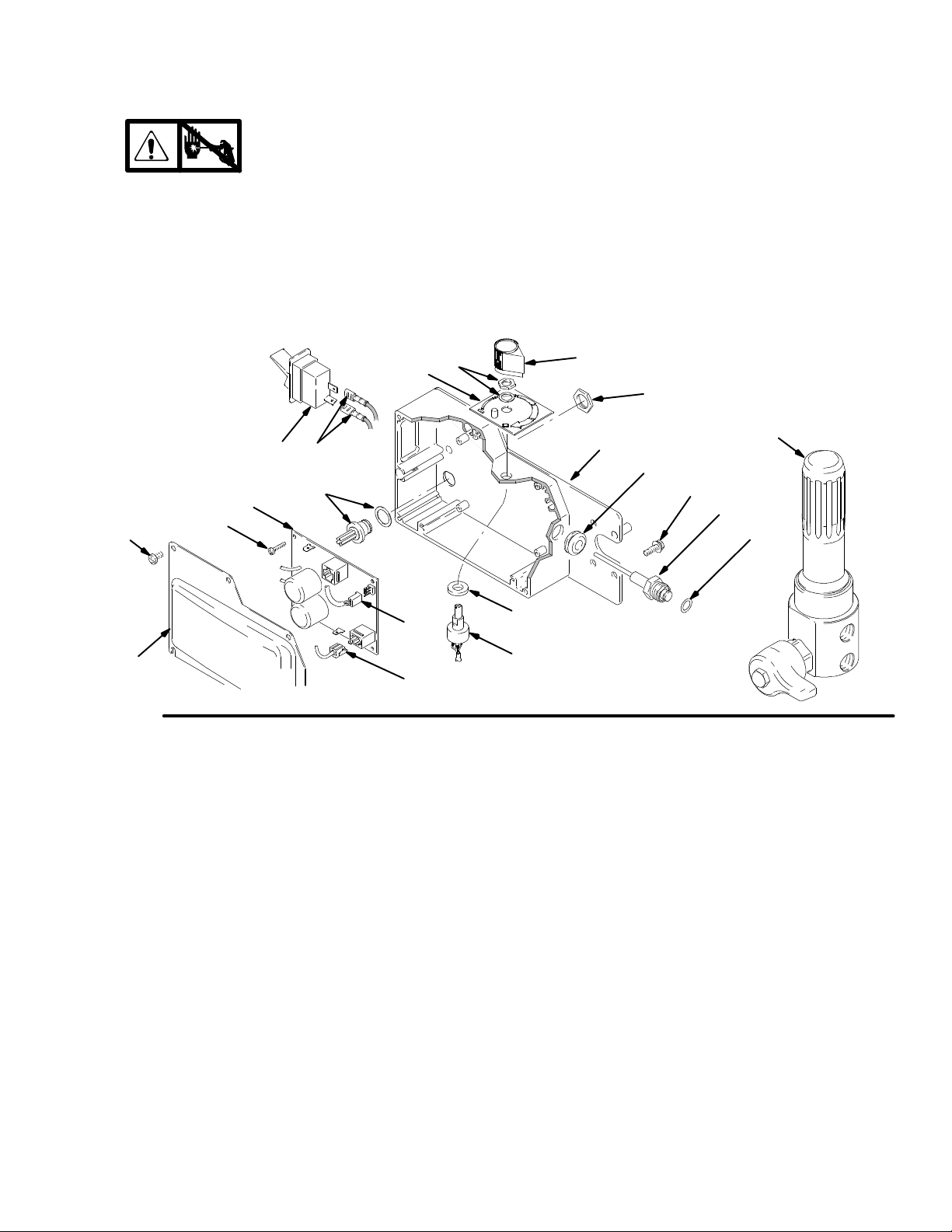
On/Off Switch
Removal
1.
2. Fig. 15. Remove five screws (307) and
cover (322).
Relieve pressure; page 5.
Installation
5. Install new ON/OFF switch (309) so tabs of switch
snap into place on inside of pressure control
housing.
6. Connect two wires (A) to ON/OFF switch.
3. Disconnect two wires (A) from ON/OFF
switch (309).
4. Press in on two retaining tabs on each side of
ON/OFF switch (309) and remove switch.
312
A309
304
D
E
1(Ref)
4(Ref)
Fig. 15
302
303
310
7. Install pressure control cover (322) with five
screws (307).
313
304
301
315
319
31 1
310
318
316
317
8711A
308874 13
Page 14

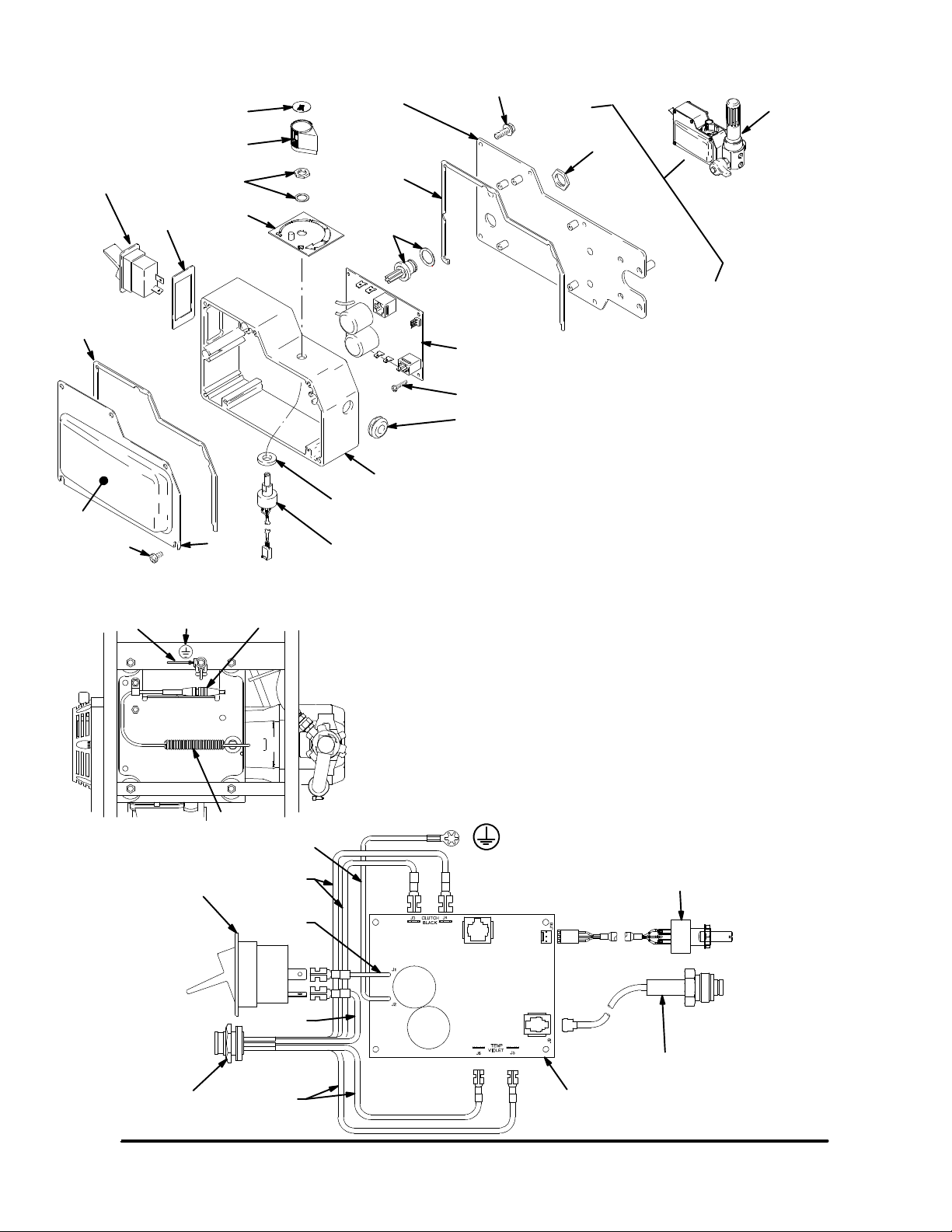
Pressure Control
Control Board
Removal
1.
2. Fig. 15. Remove five screws (307) and
cover (322).
3. Disconnect at control board (302):
D Four clutch leads: two violet and two black.
D Lead (D) from potentiometer.
D Lead (E) from transducer.
D Two red leads (A) to ON/OFF switch (309).
4. Remove four screws (303), green ground wire, and
control board (302).
Relieve pressure; page 5.
Pressure Control Transducer
Removal
1.
2. Fig. 15. Remove five screws (307) and
cover (322).
Relieve pressure; page 5.
Installation
When installing replacement control board, follow
instructions with control board to set model type.
1. Fig. 15. Install control board (302) with five
screws (303).
2. Connect control board (302):
D Two red leads (A) to ON/OFF switch (309).
D Lead (E) to transducer.
D Lead (D) to potentiometer.
D Four clutch leads: two violet and two black.
3. Install cover (322) with five screws (307).
5. Remove pressure control transducer (318z) and
packing o-ring (318aa) from filter housing (318).
Installation
1. Fig. 15. Install packing o-ring (317) and pressure
control transducer (316) in filter
housing (318). Torque to 30--35 ft-lb.
3. Disconnect lead (E) from control board (302).
4. Remove three screws (319) and filter housing
(318) from control plate (301). Carefully pull
transducer connector through rubber grommet
(315).
Pressure Adjust Potentiometer
Removal
1.
2. Fig. 15. Remove five screws (307) and
cover (322).
3. Disconnect lead (D) from control board (302).
4. Loosen set screws on potentiometer knob (313)
and remove knob, shaft nut, lockwasher (310) and
pressure adjust potentiometer (310).
5. Remove seal (311) from potentiometer (310).
30887414
Relieve pressure; page 5.
2. Carefully feed transducer connector through
rubber grommet (315). Install fluid filter (318) on
control plate (301) with three screws (319).
3. Connect lead (E) to control board (302).
4. Install cover (322) with five screws (307).
Installation
1. Fig. 15. Install seal (31 1) on potentiometer (310).
2. Install potentiometer (310), shaft nut, lockwasher
(310), and potentiometer knob (313).
a. Turn potentiometer shaft (310) clockwise to
internal stop. Assemble potentiometer knob
(313) to strike pin on plate (312) and have
bottom of knob clear plate by .040 to .060 in.
b. After adjustment of step a., tighten both set
screws in knob 1/4 to 3/8 turn after contact
with shaft.
3. Connect lead (D) to control board (302).
4. Install cover (322) with five screws (307).
Page 15

Pressure Control
Control Board Diagnostics
1. Fig. 15. Remove five screws (307) and
cover (322).
2. Start engine.
LED
BLINKS
Two times
repeatedly
Three
times repeatedly
Four times
repeatedly
Five times
repeatedly
SPRAYER OPERATION INDICATES WHAT TO DO
Sprayer shuts down and LED continues to blink two times repeatedly
Sprayer shuts down and LED continues to blink three times repeatedly
Sprayer shuts down and LED continues to blink four times repeatedly
Sprayer shuts down and LED continues to blink five times repeatedly
3. Turn ON/OFF switch ON.
4. Observe LED operation and reference following
table:
Run away pressure.
Pressure greater than
4500 psi (310 bar, 31
MPa).
Pressure transducer is
faulty or missing
Generator voltage is
low
High clutch current 1. Check clutch 5-pin bulkhead con-
1. Check pressure transducer connection at control board
2. Replace pressure transducer
3. Replace control board
1. Check pressure transducer connection at control board
2. Replace pressure transducer
3. Replace control board
1. Increase engine throttle
2. Check wiring connections
3. Service Honda engine alternator
nector. Clean contacts.
Six times
repeatedly
Sprayer shuts down and LED continues to blink six times repeatedly
2. Measure 1.2 ¦ 0.2 (LL 3900);
1.7 ¦ 0.2 (LL 5900) across
clutch field at 70_F
3. Replace clutch field assembly
High clutch temperature 1. If clutch is new, let sprayer cool
down and then restart
2. Inspect clutch. Replace clutch if
there is excessive wear.
3. Remove pump pin, separate gear
box from clutch housing. Rotate
rotor clockwise to check for excessive drag in gear box.
308874 15
Page 16

Displacement Pump
Removal
1. Fig. 16. Flush pump.
2.
3. Cycle pump until piston rod (A) is in its lowest
position.
4. Remove suction/drain hose (27).
27
Fig. 16
Relieve pressure; page 5.
A
Repair (
See manual 308798 for pump repair instructions)
8828A
5. Fig. 17. Use screwdriver: push retaining spring up
and push out pin (82).
82
Fig. 17
6. Fig. 18. Loosen locknut by hitting firmly with a
20 oz (maximum) hammer. Unscrew pump.
Fig. 18
7675B
7673B
Installation
WARNING
If pin works loose, parts could break off due to
force of pumping action and project through the air
and cause serious injury or property damage.
CAUTION
If the pump locknut loosens during operation, the
threads of the bearing housing will be damaged.
1. Fig. 19. Pull piston rod out 1.5 in. Screw in pump
until holes in bearing cross link and piston rod
align.
1.5 in.
3. Fig. 20. Screw jam nut down onto pump until nut
stops. Screw pump up into bearing housing until it
is stopped by jam nut. Back off pump and jam nut
to align pump outlet to back. Tighten jam nut by
hand, then tap 1/8 to 1/4 turn with a 20 oz hammer
to approximately 75 5ft--lb(102N¡m).
Fig. 20
4. Fig. 21. Fill packing nut with Graco TSL, through
the slit, until fluid flows onto the top of seal.
7673B
Fig. 19
2. Fig. 17. Push pin (82) into hole, and push retaining
spring into groove around connecting rod.
30887416
7676B
Fig. 21
7677B
Page 17

Parts -- LineLazer II
Models 232651 and 232661
18
18
C (Sheet 3)
59
130
60
58
3
1
101
B (Sheet 3)
102
60
61
62
A (Sheet 2)
74
26
125
1
54
30
1
49
1
76
55
97
2
50
96 (LL 3900)
97 (LL 5900)
28
2
55
75
75
108
68
D (Sheet 3)
100
1
2
25 Ref
23
129
67
66
65
Label
LL 3900 only
24
130
69
68
25 Ref
69
68
165
68
70
69
38
1
71
Sheet 1 of 5
55
104
1 18b
68
105
55
74
68
72
118
54
56
1 18e
103
127
39
1
128
54
109
E (Sheet 3)
126
1 18a
F (Sheet 4)
124
143
1 18c
1 18d
1 18f
8824C
308874 17
Page 18

Parts -- LineLazer II
Models 232651 and 232661 (Cont’d)
51
85
77
50
84
32
31
78
119
120
91
50
52
88
27a
27e
27f
86
29
25
107
27h
27g
27j
27d
83
81
82
80
17
87
27b
50
53
79
91
94
95
91
50
98
89
99
33
8831A
92
1 Label
30887418
27c
Detail A
27d
Sheet 2 of 5
74 Ref 106
145
62 Ref
1
8837A
Page 19

Parts -- LineLazer II
Models 232651 and 232661 (Cont’d)
1
152,16
17 Ref
11
14
15
5
13
146
63
6
9
57
25 Ref
17 Ref
8832A 8836A
12
25 Ref
64
61 Ref
62
8
1
7
61
2
4
Detail B
110
19
111
112
113
114 111
115
112
Detail C
Sheet 3 of 5
8833B
308874 19
Page 20
Parts -- LineLazer II
34
35
128
36
Models 232651 and 232661 (Cont’d)
44
45
46
48
48b
48e
48m
48c
48d
43
41
48f
42
48n
40
58 Ref
48k
47
48a
48g
48c
48h
48j
17
58
102 Ref
Detail D
37 Ref
116
Detail E
Sheet 4 of 5
140
117 Ref
8835A
141
8834A
30887420
Page 21

Parts -- LineLazer II
Models 232651 and 232661 (Cont’d)
1 18ad
A
A
1 18ac
Top View
1 18ae
C
wheel
1 18af1 18aa
1 18ab
A
A
3(Ref)
1 18ah
1 18ag
1 18ap 118aq
B
F
1 18am 118an 1 18ab(Ref)
1 18ak
1 18aj
1 18ar
A
G
D
1 18as
A--A
1 18at
1 18aa(Ref)
1 18af(Ref)
E
1 18av
1 18au
8838A
Detail F
Sheet 5 of 5
308874 21
Page 22

Models 232651 and 232661
Parts -- LineLazer II
Ref
No. Part No. Description Qty
1 114631 SCREW, thread forming, hex hd 5
2 PRESSURE CONTROL Parts, page 26 1
3 194071 LABEL, identification 1
4 241444 COVER, abs, painted 1
5 114955 CONTROL, throttle 1
6 109466 NUT, lock, hex 2
7 112380 SCREW, machine, pan hd 2
8 194314 LABEL, warning 1
9 114954 SWITCH, rocker 1
10 1 14271 STRAP, retaining 1
1 1 240797 HOSE, coupled, 3/8 in. x 50 ft 1
12 196176 NIPPLE, adapter 2
13 196177 ADAPTER 1
14 196179 ELBOW, street 1
15 196178 NIPPLE, pipe 1
16 196181 NIPPLE 1
17 241000 HOSE, coupled, 1/4 in. x 7 ft 2
18 1 14659 GRIP, handle 2
19 224144 TRIGGER, linestriper 1
20 1 11482 RIVET, snap 2
21 1 11484 STRAP, nylon, tie 2
23 194328 TUBE, nylon 1
24 240705 HANDLE, linestriper 1
25 240791 HOSE, coupled, 3/8 in. x 2.4 ft 1
26 241005 KIT, cover, pail 1
27 241340 REP AIR KIT, suction hose 1
27a 170957 . TUBE, suction 1
27b 185381 . HOSE, nylon 1
27c 110194 . UNION, swivel, 180 1
27d 101818 . CLAMP, hose 2
27e 193711 . GASKET, pail 1
27f 181072 . STRAINER, inlet 1
27g 194298 . TUBE, drain 1
27h 241718 . DEFLECTOR 1
27j 196180 . BUSHING 1
28 1 14690 STRAP 2
29 1 14418 SCREW, self tap, fil hd 4
30 LABEL, identification
194069 LL 3900 1
194070 LL 5900 1
31 SCREW
107210 LL 3900 4
1 14666 LL 5900 4
32 1061 15 WASHER, lock spring 4
33 ENGINE
108879 LL 3900 1
1 14530 LL 5900 1
34 188135 GUIDE, cable 1
35 1 14029 CLAMP, swivel, adjustable 1
36 181734 ARM, support 1
37 193665 BRACKET, cable 1
Ref
No. Part No. Description Qty
38 186821 LABEL, warning 2
39 240780 BRACKET, arm, gun 2
40 243284 GUN, flex, basic 1
41 100016 WASHER, lock 2
42 100021 SCREW, cap, hex hd 2
43 241001 HOLDER, gun 1
44 100133 WASHER, lock 2
45 100101 SCREW, cap, hex hd 1
46 186699 BLOCK, mounting, cable 1
47 101345 NUT, hex, jam 1
48 1 11230 SCREW, machine, fil hd 1
48a 186747 LEVER, actuator 1
48b 100846 FITTING, lubrication 1
48c 111016 BEARING, flanged 2
48d 100015 NUT, hex, 1/4--20 1
48e 110755 WASHER 1
48f 181818 KNOB 1
48g 111045 SCREW, shoulder, sch, 5/16 x 1 in. 1
48h 101345 NUT, hex, 1/4--20 2
48j 108535 BEARING, sleeve 1
48k 107445 CAPSCREW, sch, 1/4--20 x 1--1/2 in. 1
48m 181795 JAW, clamp 1
48n 108483 SCREW, shoulder, 1/4 x 3/8 ins 1
49 194125 LABEL, danger, English 1
50 105510 WASHER, lock, spring 17
51 SCREW, cap, soc. hd
107218 LL 3900 2
104008 LL 5900 10
52 SCREW, cap, soc. hd
101682 LL 3900 4
1 14686 LL 5900 8
53 SCREW, hex, soc. hd
108803 LL 3900 10
108803 LL 3900 6
54 1 10837 SCREW, flange, hex 3
55 1 11040 NUT, lock, nylock 5
56 189919 BLANK, label 1
57 196182 UNION, swivel, 90_ 1
58 241418 REP AIR KIT, cable 1
59 1 12798 SCREW, thread forming, hex hd 1
60 237686 CLAMP, grounding assembly 1
61 1 10838 NUT, lock 4
62 1 14647 CABLE, power 1
63 241294 CONDUCTOR, electrical 1
64 241293 CONDUCTOR, electrical 1
65 1 14648 CAP, dust 2
66 1 12405 NUT, lock 3
67 1 11020 WHEEL, pneumatic 2
68 101566 NUT, lock 18
69 1 11194 SCREW, cap, flange hd 6
70 193405 AXLE 1
30887422
Page 23

Parts -- LineLazer II
Models 232651 and 232661 (Cont’d)*
Ref
No. Part No. Description Qty
71 186812 CHAIN, ground, 3.5 hp 1
72 100731 WASHER 3
73 1 14653 SCREW, cap, flange hd 1
74 240999 CONDUCTOR, ground 2
75 1 10963 SCREW, cap, flange hd 2
76 108868 CLAMP, wire 2
77 1 14699 WASHER, thrust 1
78 GEAR, combination
241439 LL 3900 1
241440 LL 5900 1
79 1 14672 WASHER, thrust 3
80 DISPLACEMENT PUMP
239923 LL 3900 1
240291 LL 5900 1
81 NUT, retaining
192723 LL 3900 1
193031 LL 5900 1
82 PIN, STRAIGHT
176818 LL 3900 1
183210 LL 5900 1
83 SPRING, retaining
176817 LL 3900 1
183169 LL 5900 1
84 BEARING HOUSING
240523 LL 3900 1
241015 LL 5900 1
85 CONNECTING ROD
241008 LL 3900 1
241012 LL 5900 1
86 COVER, housing
179899 LL 3900 1
241308 LL 5900 1
87 DRIVE HOUSING; Parts, page 25
241007 LL 3900 1
24101 1 LL 5900 1
88 PINION HOUSING; Parts, page 25
241 108 LL 3900 1
241 112 LL 5900 1
Ref
No. Part No. Description Qty
92 CLUTCH HOUSING
193540 LL 3900 1
193531 LL 5900 1
94 193680 COLLAR, shaft 1
95 183401 KEY, parallel 1
96 SCREW, cap, hex hd
100469 LL 3900 1
101864 LL 5900 4
97 WASHER, plain
108851 LL 3900 1
1 13802 LL 5900 1
98 SCREW, cap, soc. hd
109031 LL 3900 4
108842 LL 5900 4
99 WASHER, lock, spring
104008 LL 3900 4
100214 LL 5900 4
100 104766 MOUNT, motor 4
101 194310 LEVER, actuator 1
102 241445 CABLE 1
103 193693 BRACKET, mounting 1
104 114808 CAP, vinyl 1
105 193692 ROD, brake 1
106 186620 LABEL, symbol, ground 1
107 NIPPLE, adapter
196176 LL 3900 2
196178 LL 5900 1
108 193677 PLATE, mounting 1
109 106212 SCREW, cap, hex hd 4
1 10 190098 TRIGGER, pivot 1
1 11 111017 BEARING, flange 2
1 12 186696 PLATE, lever, pivot 2
1 13 100718 WASHER 1
1 14 107110 LOCKNUT 1
1 15 111235 SCREW, mach, pan hd 1
Y Danger & Warning labels, tags, and cards are free.
89 100644 SCREW, cap, soc. hd 5
91 KIT, clutch**
241 109 LL 3900 (4 in.) 1
241 113 LL 5900 (5 in.) 1
* Models 233011 through 233014 include European
Pail Cover and Holder 240717 and Pressure Gauge
Kit 241339
** Includes rotor, armature, and hub.
308874 23
Page 24

Parts -- LineLazer II
Ref
No. Part No. Description Qty
1 16 114682 SPRING, compression 1
1 17 114802 STOP, wire 1
1 18 240719 KIT ASSY, wheel/swivel 1
1 18a 240719 . CASTER ASSY, swivel 1
1 18aa 240940 . . KIT, repair, bracket, hub 1
includes 118aj (2) and 118ah (1)
1 18ab 240942 . . SHAFT , fork 1
1 18ac 193528 . . ARM, detent 1
1 18ad 193662 . . PIN, locking, tapered 1
1 18ae 110754 . . SCREW, cap, soc hd 2
1 18af 181818 . . KNOB, pronged 1
1 18ag 114548 . . BEARING, bronze 2
1 18ah 113484 . . SEAL, grease 1
1 18aj 113485 . . BEARING, cup/cone 2
1 18ak 112825 . . SPRING, belleville 1
1 18am 112405 . . NUT, lock 1
1 18an 114648 . . CAP, dust 1
1 18ap 107194 . . WASHER, plain 1
1 18aq 108000 . . NUT , lock 1
1 18ar 1 13962 . . WASHER, hardened 1
1 18as 114681 . . SCREW, cap, hex hd 1
1 18at 193660 . . DISK, adjuster 1
1 18au 193661 . . JAW 1
1 18av 108483 . . SCREW, shoulder, soc hd 1
1 18b 113471 . SCREW, cap, hex hd 1
1 18c 112405 . NUT, lock 1
1 18d 1 12825 . WASHER, Belleville 1
1 18e 193658 . SPACER, seal 2
1 18f 114549 . WHEEL, pneumatic 1
Ref
No. Part No. Description Qty
119 LOCKWASHER
105510 LL 3900 4
104008 LL 5900 4
120 SCREW, cap, soc. hd
100644 LL 3900 4
101864 LL 5900 4
124 240991 BRACKET, caster, front 1
125 194126 LABEL, warning 1
126 240704 FRAME, linestriper 1
127 108471 KNOB, pronged 2
128 224052 BRACKET, support gun 1
129 114958 STRAP, tie 7
130 178342 CLIP, spring 4
138 206994 THROAT SEAL LIQUID; not shown 1
140 243161 GUARD, tip, spray, cylinder 1
141 LL5319 TIP , spray, cylinder 1
143 114982 SCREW, cap, flange hd 2
144 114956 TERMINAL (not shown) 1
145 194438 WRAP , corrugated 1
146 240131 PLUG, fitting 1
147 404378 CLAMSHELL (not shown) 1
150 115077 PAIL (not shown) 1
151 SPACER
19441 1 LL 3900 1
194172 LL 5900 1
152 195119 LABEL, caution 1
165 194953 SHIELD, control 1
Y Danger & Warning labels, tags, and cards are free.
30887424
Page 25

Parts -- Drive and Pinion Housings
88e
88d
88b
120 (Ref)
119 (Ref)
88 (Ref)
87h
87g
79 (Ref)
2
1
78 (Ref)
1
Only used on LineLazer 3900.
Pinion housing 88 includes clutch field and connector.
2
Ref No. 87 and 88
Ref No. 88: Pinion Housing Assembly 241108 for
LL 3900; Pinion Housing Assembly 241112 for
LL 5900
Ref
No. Part No. Description Qty
88 PINION HOUSING 1
88b 105489 PIN 2
88d* PINIONSHAFT
241110 LL 3900 1
241114 LL 5900 1
88e* RETAININGRING,large
113094 LL 3900 1
112770 LL 5900 1
*Must be ordered separately.
79 (Ref)
87 (Ref)
50 (Ref)
51 (Ref)
77 (Ref)
TI0177A
Ref No. 87: Drive Housing Assembly 241007 for
LL 3900; Drive Housing Assembly 241011 for
LL 5900
Ref
No. Part No. Description Qty
87 DRIVEHOUSING ASSEMBLY
87g* WASHER
107089 LL 3900 1
194173 LL 5900 1
87h* WASHER
194411 LL 3900 1
194172 LL 5900 1
*Must be ordered separately.
308874 25
Page 26
Parts -- Pressure Control
301
314
319
318
305
323
1(Ref)
309
308
313
310
312
31 1
4(Ref)
310
Wiring Diagrams
62(Ref)74(Ref) 106(Ref)
8837A
305
304
306
304
302
REF
NO. PART NO. DESCRIPTION QTY
303
315
(see page 22, item 2 for next higher assembly)
301 193653 PLA TE, control 1
302 241093 BOARD, PC 1
303 1 11839 SCREW, machine, pan hd,
304 240776 HARNESS, wiring. 1
305 193497 GASKET, control 2
306 193652 HOUSING, control box 1
308 193052 PLA TE, instruction 1
309 1 14277 SWITCH, rocker, (dpst) 1
310 241443 POTENTIOMETER, pressure
31 1 193657 O-RING, packing 1
312 193654 PLA TE, instruction 1
313 1 14273 KNOB, potentiometer 1
314 193072 LABEL, control 1
315 1 14629 GROMMET, transducer 1
316 240314 TRANSDUCER, pres. cont. 1
317 1 11457 P ACKING, o--ring 1
318 FLUID FILTER; Parts, page 27 1
319 1 10997 SCREW, flange, hex 3
320 1 14532 TIE, wire, twist 1
322 241444 COVER, pressure control 1
323 194071 LABEL, identification 1
PRESSURE CONTROL REF
6--32x1/2in. 5
control 1
(see page 27 for parts location)
(see page 27 for parts location)
Fig. 22
145(Ref)
Green
309
(Ref)
Black (--)
310 (Ref)
Red (+)
Potentiometer
Red (+)
Pressure
transducer
316
(Ref)
304
(Ref)
Violet
302
(Ref)
8716A
30887426
Page 27

Parts -- Fluid Filter
318f
318e
318d
318k
318j
317
318l
316
318b
318n
318h
318m
318g
318c
318a
8716A
REF
NO. PART NO. DESCRIPTION QTY
(see page 26, item 318 for next higher assembly)
318a . 193651 HOUSING, filter 1
318b . 104361 O-RING 1
318c . 186075 SUPPORT, filter 1
318d . 167025 STRAINER, mesh, 60 1
318e . 171941 SPRING, compression 1
318f . 192706 BOWL, filter 1
318g* . 193710 SEAT, valve 1
318h* . 193709 SEAT, valve 1
318j* . 194102 HANDLE, valve 1
318k* . 116424 NUT, cap, hex hd 1
318l* . 114708 SPRING, compression 1
318m*. 114797 GASKET 1
318n* . 245103 VALVE 1
316 240314 TRANSDUCER, pres. cont. REF
(see item 316 page 26 for parts list)
317 1 11457 PACKING, o--ring REF
(see item 317 page 26 for parts list)
*Part of 245103 Drain Valve Replacement Kit.
308874 27
Page 28

Complete Sprayers with 2nd Gun Kit
Models 232652, 232662 with 2nd Gun Kit
Ref
No. Part No. Description Qty
232652 LineLazer II 3900 1
See parts liston page 17
232662 LineLazer II 5900 1
See parts liston page 17
201 241284 KIT, second gun and hose 1
Parts,manual 308939
Accessories
DANGER LABELS
An English language DANGER label is on your
sprayer. If you have painters who do not read English, order one of the following labels to apply to
your sprayer. The drawing shows the best placement of these labels for good visibility.
Order the labels from your Graco distributor.
Apply other
language here
French 194931
Spanish 194932
German 194933
Greek 194934
Korean 194935
English 194125
15 Gallon Paint Hopper Kit 241104
Provides large material capacity for LL 3900/LL5900.
15 Gallon Paint Hopper Kit 241103
Provides large material capacity for LL 3500/LL5000.
(Note: for LL3500 also order
Caster Wheel Replacement Kit 240719
Replacement caster wheel.
Suction Tube Kit
03497A
238962).
201
Displacement Pump Repair Kit
Packing repair kit.
LineLazer 3900 239928
LineLazer 5900 240248
European Pail Cover and Holder 240717
Flex Gun Repair Kit 235474
Includes needle, gasket, diffuser/seat.
Glass Bead Application Systems
An application system for applying glass beads.
One Dispenser System (complete system) 241447
Two Dispenser System (complete system) 241100
Dispenser Kit (includes dispenser and hose) 241448
Two Dispenser System 241530
(for LL 3500 and LL 5000)
Line Pointer Kits
Used as pointer guides for line application.
Short 241101
Long 241102
Pressure Gauge Kit 241339
Reverse Handlebar Kit 240714
Allows application from either front or back of unit.
8807A
Swivel Wheel Kit 241105
Swivel wheel replacement kit for LL 3500 and LL 5000.
30887428
Page 29

Technical Data
Honda GX120 Engine
Power Rating @ 3600 rpm
ANSI 4.0 Horsepower.......................
DIN 6270B/DIN 6271
NA 2.1 Kw -- 2.8 Ps......................
NB 2.6 Kw -- 3.6 Ps......................
Honda GX160 Engine
Power Rating @ 3600 rpm
ANSI 5.5 Horsepower.......................
DIN 6270B/DIN 6271
NA 2.9 Kw -- 4.0 Ps......................
NB 3.6 Kw -- 4.9 Ps......................
Maximum working pressure 3300 psi...............
(227 bar, 22.7 MPa)
Noise Level
Sound power 105 dBa.........................
per ISO 3744
Sound pressure 96 dBa........................
measured at 3.1 feet (1 m)
Cycles/gallon (liter)
LineLazer II 3900 104 (27.5)....................
LineLazer II 5900 104 (27.5)....................
Dimensions
Maximum delivery
LineLazer II 3900 1.15 gpm (4.4 liter/min)........
LineLazer II 5900 1.5 gpm (5.7 liter/min)..........
Maximum tip size
LineLazer II 3900 1 gun with 0. 034 in. tip........
2 guns with 0.024 in. tip
LineLazer II 5900 1 gun with 0. 041 in. tip........
2 guns with 0.028 in. tip
Inlet paint strainer 16 mesh (1190 micron)...........
stainless steel screen, reusable
Outlet paint filter 60 mesh (250 micron).............
stainless steel screen, reusable
Pump inlet size 3/4 in. npt (m)......................
Fluid outlet size 1/4 npsm from fluid filter............
Wetted parts
Displacement Pump stainless steel, carbon steel,..
polyurethane, UHMW polyethylene,
Delrin
r
, leather
Filter aluminum, carbon steel, stainless steel.......
NOTE: Delrinris a trademarkof the DuPont Company.
Model 232651, 233011
Complete Sprayer
Weight (dry, without packaging) 212 lb (96 kg).......
Height 40 in. (101.6 cm)..........................
Length 65 in. (165.1 cm)..........................
Width 32 in. (81.3 cm)............................
Model 232661, 233013
Complete Sprayer
Weight (dry, without packaging) 232 lb (105 kg)......
Height 40 in. (101.6 cm)..........................
Length 65 in. (165.1 cm)..........................
Width 32 in. (81.3 cm)............................
LineLazer II 3900
Model 232652, 233012
Complete Sprayer with 2nd Gun Kit
Weight (dry, without packaging) 222 lb (101 kg)......
Height 40 in. (101.6 cm)..........................
Length 65 in. (165.1 cm)..........................
Width 32 in. (81.3 cm)............................
LineLazer II 5900
Model 232662, 233014
Complete Sprayer with 2nd Gun Kit
Weight (dry, without packaging) 242 lb (110 kg)......
Height 40 in. (101.6 cm)..........................
Length 65 in. (165.1 cm)..........................
Width 32 in. (81.3 cm)............................
308874 29
Page 30

Graco Warranty
Gracowarrantsallequipmentmanufacturedby Gracoandbearingitsnametobefreefromdefectsinmaterialandworkmanshiponthe
dateofsaleby anauthorizedGracodistributortotheoriginalpurchaser foruse. Withtheexceptionofany special,extended,orlimited
warranty publishedbyGraco,Gracowill,fora periodoftwelve monthsfromthedateofsale, repairor replaceany partoftheequipment
determined by Graco to be defective. This warranty applies only when the equipment is installed, operated and maintained in
accordance with Graco’s written recommendations.
Thiswarrantydoes not cover,andGracoshallnotbeliableforgeneralwearandtear,or any malfunction,damageorwear caused by
faulty installation, misapplication, abrasion, corrosion, inadequate or improper maintenance, negligence, accident, tampering, or
substitutionof non-Gracocomponentparts. NorshallGracobeliableformalfunction,damageorwearcausedby theincompatibilityof
Graco equipmentwithstructures,accessories,equipmentor materialsnotsuppliedbyGraco,ortheimproper design,manufacture,
installation, operation or maintenance of structures, accessories, equipment or materials not supplied by Graco.
This warrantyisconditionedupon the prepaid returnoftheequipmentclaimedtobedefectivetoan authorizedGraco distributor for
verificationoftheclaimed defect. Ifthe claimed defectisverified,Graco willrepairorreplacefreeofcharge any defective parts. The
equipmentwillbe returnedtotheoriginalpurchasertransportationprepaid. Ifinspectionoftheequipmentdoesnotdiscloseanydefect
in material or workmanship, repairs will be made at a reasonable charge, which charges may include the costs of parts, labor, and
transportation.
THIS WARRANTYIS EXCLUSIVE, AND IS IN LIEU OF ANY OTHER WARRANTIES,EXPRESSOR IMPLIED,INCLUDINGBUT
NOT LIMITED TO WARRANTY OF MERCHANTABILITY OR WARRANTY OF FITNESS FOR A PARTICULAR PURPOSE.
Graco’ssoleobligationandbuyer’ssoleremedyforany breachofwarrantyshall beassetforthabove. The buyeragreesthatnoother
remedy(including,but notlimitedto, incidentalorconsequential damages forlostprofits,lostsales,injuryto personorproperty,orany
otherincidentalorconsequentialloss)shallbeavailable. Any actionforbreachof warrantymustbebrought withintwo(2)yearsofthe
date of s ale.
Graco makes no warranty,and disclaims all implied warranties of merchantability and fitness for a particular purpose in connection
withaccessories,equipment,materialsor componentssoldbut notmanufacturedbyGraco. These items sold,butnot manufactured
by Graco (such as electric motors,switches,hose,etc.), are subject to the warranty,ifany,oftheirmanufacturer. Graco willprovide
purchaser with reasonable assistance in making any claim for breach of these warranties.
In no event will Graco be liable for indirect,incidental,specialorconsequentialdamagesresultingfromGracosupplyingequipment
hereunder, or the furnishing, performance, or use of any products or other goods sold hereto, whether due to a breach of contract,
breach of warranty,the negligence of Graco, or otherwise.
FOR GRACO CANADA CUST
Thepartiesacknowledgethat theyhaverequiredthatthe presentdocument,aswell asalldocuments,noticesand legal proceedings
entered into, given or instituted pursuant hereto or relating directly or indirectly hereto, be drawn up in English. Les parties
reconnaissentavoirconvenuquelarédaction du présentedocumentsera en Anglais, ainsiquetousdocuments,avis etprocédures
judiciairesexécutés,donnés ouintentésà lasuitede ou en rapport,directementou indirectement,avec les proceduresconcernées.
OMERS
ADDITIONAL WARRANTY COVERAGE
Graco does provide extended warranty and wear warranty for products described in the “Graco Contractor Equipment Warranty
Program”.
Graco Phone Number
TO PLACE AN ORDER, contact your Graco distributor, or call this number to identify the distributor closest to you:
1--800--690--2894 Toll Free
All writtenand visual data contained in this document reflectthe latest product informationavailableat the time of publication.
Graco reserves the rightto make changes at any time without notice.
Originalinstructions.This manual contains English.MM 308874.
International Offices:Belgium,China, Japan, Korea
Graco Headquarters: Minneapolis
GRACO INC. AND SUBSIDIARIES P.O. BOX 1441 MINNEAPOLIS, MN 55440--1441 USA
Copyright 1999, Graco Inc. All Graco manufacturing locations are registered to ISO 9001
www.graco.com
Revision P -- July 2017
30887430
 Loading...