

Page 1
Operation, Repair, Parts
LineLazer ES 2000
LineLazer ES 1000
LineLazer™ ES 1000 / ES 2000
Airless Line Striper
For the application of line striping materials.
For professional use only.
Not approved for use in explosive atmospheres or hazardous locations.
Maximum Operating Pressure: 3300 psi (22.8 MPa, 228 bar)
Important Safety Instructions
Read all warnings and instructions in this manual and in related manuals
before using the equipment. Be familiar with the controls and the proper
usage of the equipment. Save these instructions.
Related Manuals:
ES 1000 ES 2000
311254 Gun 311254 Gun
334599 Pump 310643 Pump
3A3428 Auto-Layout Application Methods
3A4603F
EN
Use only genuine Graco replacement parts.
The use of non-Graco replacement parts may void warranty.
Page 2

Contents
Contents
Models . . . . . . . . . . . . . . . . . . . . . . . . . . . . . . . . . . . 4
Warnings . . . . . . . . . . . . . . . . . . . . . . . . . . . . . . . . . 5
Component Identification (ES 1000) . . . . . . . . . . . 9
Component Identification (ES 2000) . . . . . . . . . . 10
Tip Selection . . . . . . . . . . . . . . . . . . . . . . . . . . . . . 11
Battery and Charger . . . . . . . . . . . . . . . . . . . . . . . 12
Battery Type and Charging Profiles . . . . . . . . . 12
Battery Disposal . . . . . . . . . . . . . . . . . . . . . . . . 12
Charging the Battery . . . . . . . . . . . . . . . . . . . . . 13
Grounding Procedure
(AC Wall Power) . . . . . . . . . . . . . . . . . . . . . . . 14
Power Requirements . . . . . . . . . . . . . . . . . . . . 14
Extension Cords . . . . . . . . . . . . . . . . . . . . . . . . 14
Pails . . . . . . . . . . . . . . . . . . . . . . . . . . . . . . . . . 14
Grounding Procedure
(Battery Power) (For Flammable Flushing Fluids
Only) . . . . . . . . . . . . . . . . . . . . . . . . . . . . . . . . . 15
Pails . . . . . . . . . . . . . . . . . . . . . . . . . . . . . . . . . 15
Pressure Relief Procedure . . . . . . . . . . . . . . . . . . 16
Setup/Startup . . . . . . . . . . . . . . . . . . . . . . . . . . . . . 17
SwitchTip and Guard Assembly . . . . . . . . . . . . 19
Gun Placement . . . . . . . . . . . . . . . . . . . . . . . . . . . 20
Install Gun . . . . . . . . . . . . . . . . . . . . . . . . . . . . . 20
Position Gun . . . . . . . . . . . . . . . . . . . . . . . . . . . 20
Select Manual Guns . . . . . . . . . . . . . . . . . . . . . 20
Select Auto Guns (ES 2000) . . . . . . . . . . . . . . . 21
Gun Positions Chart . . . . . . . . . . . . . . . . . . . . . 22
Gun Arm Mounts . . . . . . . . . . . . . . . . . . . . . . . . 23
Change Gun Position
(Front and Back) . . . . . . . . . . . . . . . . . . . . . 23
Change Gun Position
(Left and Right) . . . . . . . . . . . . . . . . . . . . . . 23
Installation . . . . . . . . . . . . . . . . . . . . . . . . . . . . . 24
Trigger Sensor Adjustment (ES 2000) . . . . . . . 24
Gun Cable Adjustment . . . . . . . . . . . . . . . . . . . 25
Straight Line Adjustment . . . . . . . . . . . . . . . . . . 26
Handle Bar Adjustment . . . . . . . . . . . . . . . . . . . 26
Paint Stripe Width . . . . . . . . . . . . . . . . . . . . . . . . . 27
Spray Test Stripe . . . . . . . . . . . . . . . . . . . . . . . 27
Clearing Tip Clogs . . . . . . . . . . . . . . . . . . . . . . 27
Cleanup . . . . . . . . . . . . . . . . . . . . . . . . . . . . . . . . . 28
Flush Drain Tube . . . . . . . . . . . . . . . . . . . . . . . 28
Flush Hose and Gun . . . . . . . . . . . . . . . . . . . . . 29
LineLazer V LiveLook Display . . . . . . . . . . . . . . . 30
ES 2000 (Standard Series) . . . . . . . . . . . . . . . . 30
Initial Setup (ES 2000 Standard Series) . . . . . . 31
Striping Mode (ES2000 Standard Series) . . . . . 33
Measure Mode (ES2000 Standard Series) . . . . 34
Setup/Information . . . . . . . . . . . . . . . . . . . . . . . 35
Settings . . . . . . . . . . . . . . . . . . . . . . . . . . . . . . . 36
Information . . . . . . . . . . . . . . . . . . . . . . . . . . . . . 37
ES2000 (HP Auto Series) . . . . . . . . . . . . . . . . . . . . 38
LineLazer V LiveLook Display . . . . . . . . . . . . . . . 39
ES2000 (HP Auto Series) . . . . . . . . . . . . . . . . . 39
Initial Setup (ES2000 HP Auto Series) . . . . . . . 40
Striping Mode (ES2000 HP Auto Series) . . . . . . 42
Measure Mode (ES2000 HP Auto Series) . . . . . 43
Layout Mode . . . . . . . . . . . . . . . . . . . . . . . . . . . 44
Stall Calculator . . . . . . . . . . . . . . . . . . . . . . . . . 45
Angle Calculator . . . . . . . . . . . . . . . . . . . . . . . . 46
Setup/Information . . . . . . . . . . . . . . . . . . . . . . . 48
Settings . . . . . . . . . . . . . . . . . . . . . . . . . . . . . . . 49
Information . . . . . . . . . . . . . . . . . . . . . . . . . . . . . 50
Marker Layout Mode . . . . . . . . . . . . . . . . . . . . . 51
Data Logging . . . . . . . . . . . . . . . . . . . . . . . . . . . 52
Maintenance . . . . . . . . . . . . . . . . . . . . . . . . . . . . . . 53
Troubleshooting (ES 1000 & ES 2000) . . . . . . . . . 54
Mechanical/Fluid Flow . . . . . . . . . . . . . . . . . . . . 54
Electrical (ES 1000) . . . . . . . . . . . . . . . . . . . . . . 56
ES 2000 Troubleshooting . . . . . . . . . . . . . . . . . 60
Electrical (ES 2000) . . . . . . . . . . . . . . . . . . . . . . 62
Sprayer Will Not Run (ES 1000 & ES 2000) . . . 68
Sprayer Will Not Shut Off (ES 1000 & ES 2000) 70
Inverter (ES 1000 & ES 2000) . . . . . . . . . . . . . . 71
Sprayer does not have - 100 VAC for 120V units - 220
VAC for 230V units (ES 1000& ES 2000) . . . . . . 72
Battery Will Not Charge (ES 1000 & ES 2000) . 73
Parts Drawing - ES 1000 . . . . . . . . . . . . . . . . . . . . 74
Parts List - ES 1000 . . . . . . . . . . . . . . . . . . . . . . . . 75
Parts Drawing - ES 1000 . . . . . . . . . . . . . . . . . . . . 76
Parts List - ES 1000 . . . . . . . . . . . . . . . . . . . . . . . . 77
Parts Drawing - ES 1000 . . . . . . . . . . . . . . . . . . . . 78
Parts List - ES 1000 . . . . . . . . . . . . . . . . . . . . . . . . 79
Parts Drawing - ES 1000 . . . . . . . . . . . . . . . . . . . . 80
Parts List - ES 1000 . . . . . . . . . . . . . . . . . . . . . . . . 81
Swivel Wheel Assembly . . . . . . . . . . . . . . . . . . 81
Filter . . . . . . . . . . . . . . . . . . . . . . . . . . . . . . . . . . 81
Parts Drawing - ES 1000 . . . . . . . . . . . . . . . . . . . . 82
2 3A4603F Operation, Repair, Parts
Page 3

Contents
Parts List - ES 1000 . . . . . . . . . . . . . . . . . . . . . . . . 83
Gun Holder and Arm . . . . . . . . . . . . . . . . . . . . . 83
Gun Trigger . . . . . . . . . . . . . . . . . . . . . . . . . . . . 83
Parts Drawing - ES 1000 . . . . . . . . . . . . . . . . . . . . 84
Parts List - ES 1000 . . . . . . . . . . . . . . . . . . . . . . . . 85
Voltage Meter Box, 120V (ES1000 & ES2000) . . .86
Voltage Meter Box, 230V (ES1000 & ES2000) . . .86
Parts List . . . . . . . . . . . . . . . . . . . . . . . . . . . . . . . . . 87
Voltage Meter Box, 120V . . . . . . . . . . . . . . . . . . 87
Voltage Meter Box, 230V . . . . . . . . . . . . . . . . . . 87
Control Box, 120V (ES 1000) . . . . . . . . . . . . . . . . . 88
Control Box, 230V (ES 1000) . . . . . . . . . . . . . . . . . 88
Parts List . . . . . . . . . . . . . . . . . . . . . . . . . . . . . . . . . 89
Control Box, 120V (ES 1000) . . . . . . . . . . . . . . . 89
Control Box, 230V (ES 1000) . . . . . . . . . . . . . . . 89
Wiring Diagram - 120V (ES 1000) . . . . . . . . . . . . .90
Wiring Diagram - 230V (ES 1000) . . . . . . . . . . . . .91
Control Board Wiring Diagram . . . . . . . . . . . . . . . 92
110/120V (ES 1000) . . . . . . . . . . . . . . . . . . . . . . 92
230V (ES 1000) . . . . . . . . . . . . . . . . . . . . . . . . . 93
Parts Drawing - ES 2000 . . . . . . . . . . . . . . . . . . . . 94
Parts List - ES 2000 . . . . . . . . . . . . . . . . . . . . . . . . 95
Parts Drawing - ES 2000 . . . . . . . . . . . . . . . . . . . . 96
Parts List - ES 2000 . . . . . . . . . . . . . . . . . . . . . . . . 97
Parts Drawing - ES 2000 . . . . . . . . . . . . . . . . . . . . 98
Parts List - ES 2000 . . . . . . . . . . . . . . . . . . . . . . . . 99
Parts Drawing - ES 2000 . . . . . . . . . . . . . . . . . . . 100
Parts List - ES 2000 . . . . . . . . . . . . . . . . . . . . . . . 101
Parts Drawing - ES 2000 . . . . . . . . . . . . . . . . . . . 102
Parts List - ES 2000 . . . . . . . . . . . . . . . . . . . . . . . 103
Swivel Wheel Assembly . . . . . . . . . . . . . . . . . 103
Parts Drawing - ES 2000 . . . . . . . . . . . . . . . . . . . 104
Parts List - ES 2000 . . . . . . . . . . . . . . . . . . . . . . . 105
Gun Holder and Arm . . . . . . . . . . . . . . . . . . . . 105
Gun Trigger . . . . . . . . . . . . . . . . . . . . . . . . . . . 105
Parts Drawing - ES 2000 . . . . . . . . . . . . . . . . . . . 106
Parts List - ES 2000 . . . . . . . . . . . . . . . . . . . . . . . 107
Distance Sensor Replacement (ES 2000) . . . . . 108
Wiring Diagram - 120V (ES 2000) . . . . . . . . . . . . 109
Control Board Wiring Diagram . . . . . . . . . . . . . . 110
110/120V (ES2000) . . . . . . . . . . . . . . . . . . . . . 110
230V (ES2000) . . . . . . . . . . . . . . . . . . . . . . . . 111
Wiring Diagram - 230V (ES 2000) . . . . . . . . . . . . 112
World Key Symbol . . . . . . . . . . . . . . . . . . . . . . . . 113
Technical Specifications . . . . . . . . . . . . . . . . . . . 114
CALIFORNIA PROPOSITION 65 . . . . . . . . . . 114
Technical Specifications . . . . . . . . . . . . . . . . . . . 115
Technical Specifications . . . . . . . . . . . . . . . . . . . 116
End of Product Life . . . . . . . . . . . . . . . . . . . . . . . 117
Graco Standard Warranty . . . . . . . . . . . . . . . . . . 118
Graco Information . . . . . . . . . . . . . . . . . . . . . . . . 119
3A4603F Operation, Repair, Parts 3
Page 4

Models
Models
LineLazer ES 1000
Model 1 Battery
25M226
25N784
25M228
25N785
Model 2 Batteries
Included
25N550
25N551
25N552
25N559
25N560
25N553
Included
120V
230V
Standard
Series
2 Batteries
Included
120V
230V
HP Auto
Series
LineLazer ES 2000
Number of
Manual Guns
20
11
02
11
02
10
Number of
Auto Guns
120V 230V LazerGuide
1700
LazerGuide
2000
25N554
25N561
25N562
25N657
01
20
02
11
4 3A4603F Operation, Repair, Parts
Page 5
Warnings
120V US
230V
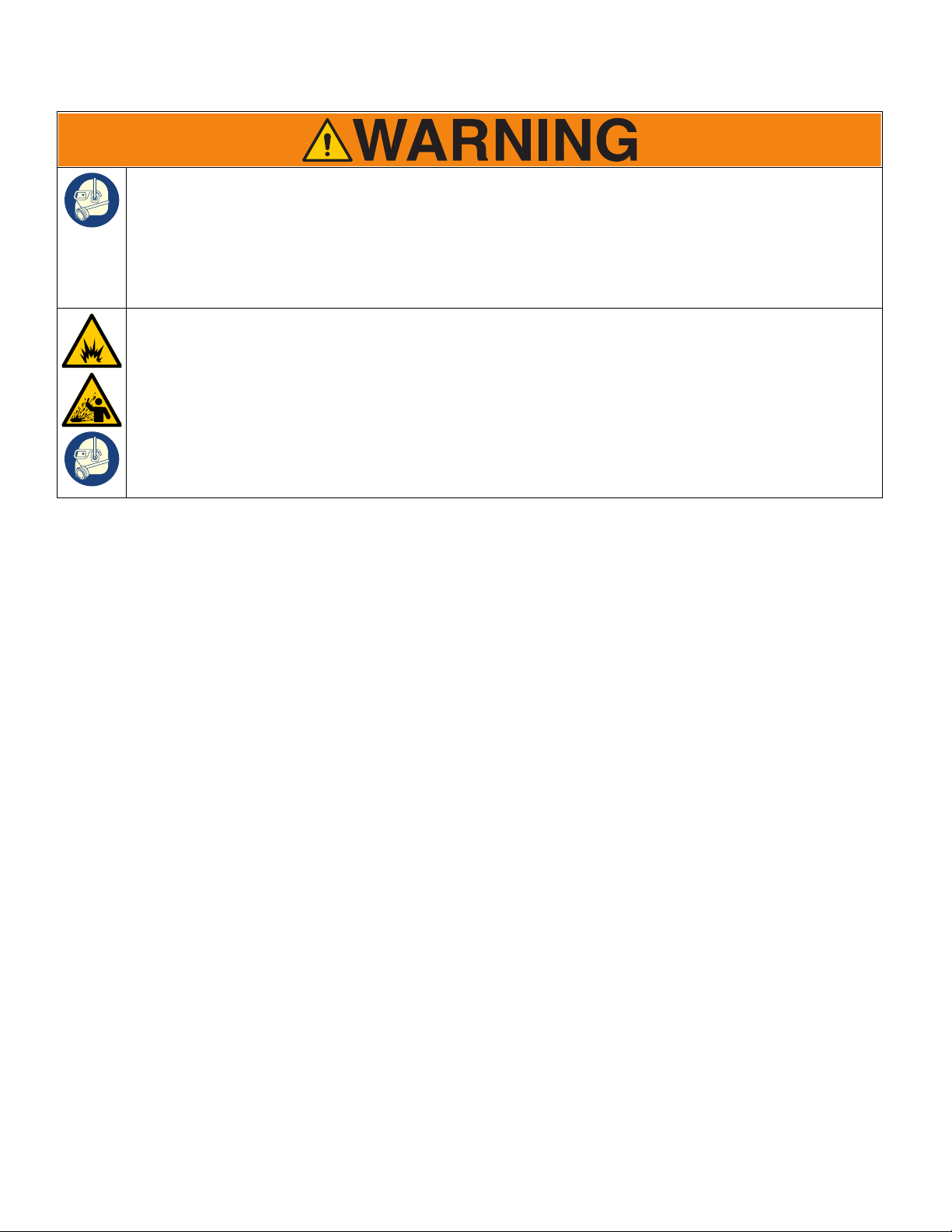
Warnings
The following warnings are for the setup, use, grounding, maintenance, and repair of this equipment. The exclamation
point symbol alerts you to a general warning and the hazard symbols refer to procedure-specific risks. When these
symbols appear in the body of this manual or on warning labels, refer back to these Warnings. Product-specific hazard
symbols and warnings not covered in this section may appear throughout the body of this manual where applicable.
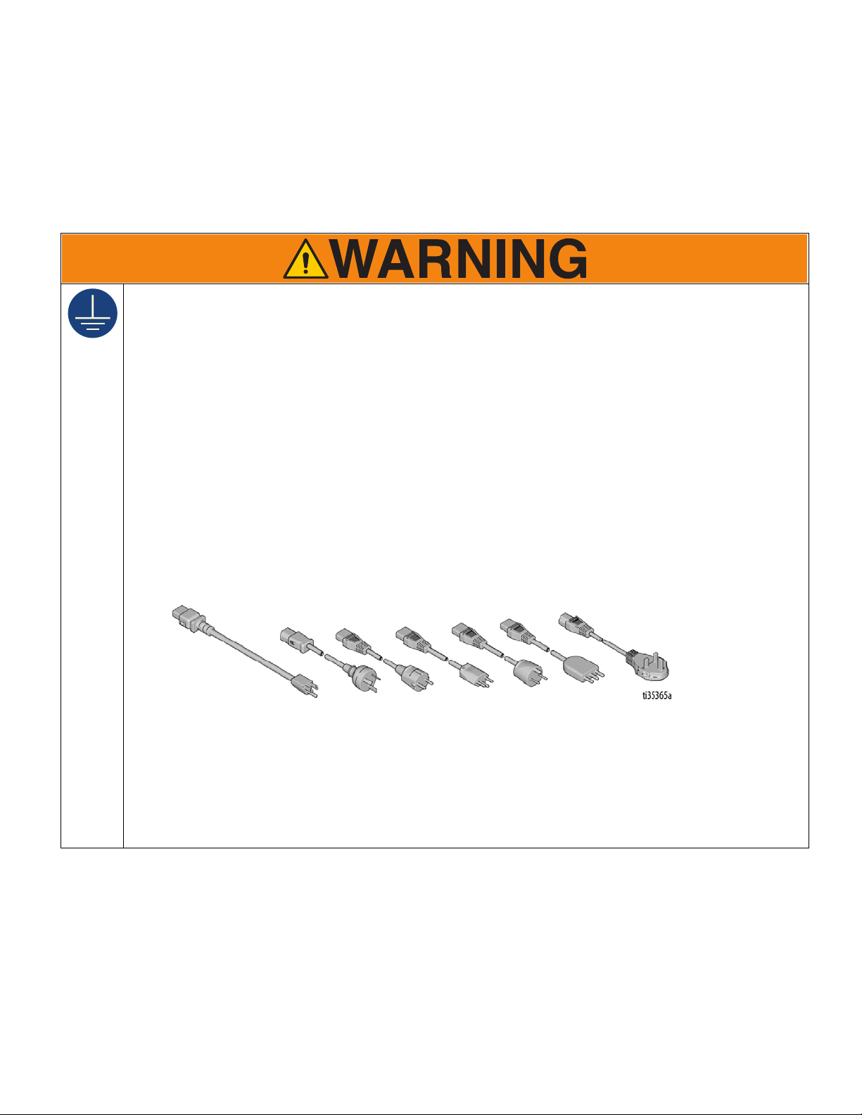
GROUNDING
This product must be grounded. In the event of an electrical short circuit, grounding reduces the risk of
electric shock by providing an escape wire for the electric current. This product is equipped with a cord having
a grounding wire with an appropriate grounding plug. The plug must be plugged into an outlet that is properly
installed and grounded in accordance with all local codes and ordinances.
• Improper installation of the grounding plug is able to result in a risk of electric shock.
• When repair or replacement of the cord or plug is required, do not connect the grounding wire to either flat
blade terminal.
• The wire with insulation having an outer surface that is green with or without yellow stripes is the grounding
wire.
• Check with a qualified electrician or serviceman when the grounding instructions are not completely
understood, or when in doubt as to whether the product is properly grounded.
• Do not modify the plug provided; if it does not fit the outlet, have the proper outlet installed by a qualified
electrician.
• This product is for use on a nominal 120V or 230V circuit and has a grounding plug similar to the plugs
illustrated in the figure below.
• Only connect the product to an outlet having the same configuration as the plug.
• Do not use an adapter with this product.
Extension Cords:
• Use only a 3-wire extension cord that has a grounding plug and a grounding receptacle that accepts the
plug on the product.
• Make sure your extension cord is not damaged. If an extension cord is necessary use 12 AWG (2.5mm
minimum to carry the current that the product draws.
• An undersized cord results in a drop in line voltage and loss of power and overheating.
3A4603F Operation, Repair, Parts 5
2
)
Page 6
Warnings
FIRE AND EXPLOSION HAZARD
Flammable fumes, such as solvent and paint fumes, in work area can ignite or explode. To help prevent fire
and explosion:
• Do not spray flammable or combustible materials near an open flame or sources of ignition such as
cigarettes, motors, and electrical equipment.
• Paint or solvent flowing through the equipment is able to result in static electricity. Static electricity creates
a risk of fire or explosion in the presence of paint or solvent fumes. All parts of the spray system, including
the pump, hose assembly, spray gun, and objects in and around the spray area shall be properly grounded
to protect against static discharge and sparks. Use Graco conductive or grounded high-pressure airless
paint sprayer hoses.
• Verify that all containers and collection systems are grounded to prevent static discharge. Do not use pail
liners unless they are antistatic or conductive.
• Connect to a grounded outlet and use grounded extensions cords. Do not use a 3-to-2 adapter.
• Do not spray flammable or combustible liquids in a confined area.
• Sprayer generates sparks. Keep spray area well-ventilated. Keep a good supply of fresh air moving through
the area.
• Keep pump assembly in a well ventilated area when spraying, flushing, cleaning, or servicing. Do not spray
pump assembly.
• Do not smoke in the spray area or spray where sparks or flame is present.
• Do not operate light switches, engines, or similar spark producing products in the spray area.
• Keep area clean and free of paint or solvent containers, rags, and other flammable materials.
• Know the contents of the paints and solvents being sprayed. Read all Safety Data Sheets (SDSs) and
container labels provided with the paints and solvents. Follow the paint and solvents manufacturer’s safety
instructions.
• Keep a working fire extinguisher in the work area.
SKIN INJECTION HAZARD
High-pressure spray is able to inject toxins into the body and cause serious bodily injury. In the event that
injection occurs, get immediate surgical treatment.
• Do not aim the gun at, or spray any person or animal.
• Keep hands and other body parts away from the discharge. For example, do not try to stop leaks with any
part of the body.
• Always use the nozzle tip guard. Do not spray without nozzle tip guard in place.
• Use Graco nozzle tips.
• Use caution when cleaning and changing nozzle tips. In the case where the nozzle tip clogs while spraying,
follow the Pressure Relief Procedure for turning off the unit and relieving the pressure before removing
the nozzle tip to clean.
• Equipment maintains pressure after power is shut off. Do not leave the equipment energized or under
pressure while unattended. Follow the Pressure Relief Procedure when the equipment is unattended or
not in use, and before servicing, cleaning, or removing parts.
• Check hoses and parts for signs of damage. Replace any damaged hoses or parts.
• This system is capable of producing 3300 psi (22.8 MPa, 228 bar). Use Graco replacement parts or
accessories that are rated a minimum of 3300 psi (22.8 MPa, 228 bar).
• Always engage the trigger lock when not spraying. Verify the trigger lock is functioning properly.
• Verify that all connections are secure before operating the unit.
• Know how to stop the unit and bleed pressure quickly. Be thoroughly familiar with the controls.
6 3A4603F Operation, Repair, Parts
Page 7
Warnings
EQUIPMENT MISUSE HAZARD
Misuse can cause death or serious injury.
• Do not operate the unit when fatigued or under the influence of drugs or alcohol.
• Do not exceed the maximum working pressure or temperature rating of the lowest rated system
component. See Technical Data in all equipment manuals.
• Use fluids and solvents that are compatible with equipment wetted parts. See Technical Data in all
equipment manuals. Read fluid and solvent manufacturer’s warnings. For complete information about your
material, request Safety Data Sheet (SDS) from distributor or retailer.
• Do not leave the work area while equipment is energized or under pressure.
• Turn off all equipment and follow the Pressure Relief Procedure when equipment is not in use.
• Check equipment daily. Repair or replace worn or damaged parts immediately with genuine manufacturer’s
replacement parts only.
• Do not alter or modify equipment. Alterations or modifications may void agency approvals and create safety
hazards.
• Make sure all equipment is rated and approved for the environment in which you are using it.
• Use equipment only for its intended purpose. Call your distributor for information.
• Route hoses and cables away from traffic areas, sharp edges, moving parts, and hot surfaces.
• Do not kink or over bend hoses or use hoses to pull equipment.
• Keep children and animals away from work area.
• Comply with all applicable safety regulations.
ELECTRIC SHOCK HAZARD
This equipment must be grounded. Improper grounding, setup, or usage of the system can cause electric
shock.
• Turn off, disconnect power cord, and disconnect battery before servicing equipment.
• Connect only to grounded electrical outlets.
• Use only 3-wire extension cords.
• Ensure ground prongs are intact on power and extension cords.
• Do not expose to rain. Store indoors.
• Wait five minutes after disconnecting power cord before servicing.
MOVING PARTS HAZARD
Moving parts can pinch, cut or amputate fingers and other body parts.
• Keep clear of moving parts.
• Do not operate equipment with protective guards or covers removed.
• Equipment can start without warning. Before checking, moving, or servicing equipment, follow the
Pressure Relief Procedure and disconnect all power sources.
TOXIC FLUID OR FUMES HAZARD
Toxic fluids or fumes can cause serious injury or death if splashed in the eyes or on skin, inhaled, or
swallowed.
• Read Safety Data Sheet (SDS) to know the specific hazards of the fluids you are using.
• Store hazardous fluid in approved containers, and dispose of it according to applicable guidelines.
BURN HAZARD
Equipment surfaces and fluid that’s heated can become very hot during operation. To avoid severe burns:
• Do not touch hot fluid or equipment.
3A4603F Operation, Repair, Parts 7
Page 8
Warnings
PERSONAL PROTECTIVE EQUIPMENT
Wear appropriate protective equipment when in the work area to help prevent serious injury, including eye
injury, hearing loss, inhalation of toxic fumes, and burns. This protective equipment includes but is not limited
to:
• Protective eyewear, and hearing protection.
• Respirators, protective clothing, and gloves as recommended by the fluid and solvent manufacturer.
BATTERY HAZARD
Lead-acid batteries produce explosive gases and contain sulfuric acid that can cause severe burns. To avoid
sparks and injury when handling or working with a lead-acid battery:
• Only use the battery type specified for use with the equipment. See Technical Data.
• Read and follow the battery manufacturer’s warnings.
• Exercise caution when working with metallic tools or conductors to prevent short circuits and sparks.
• Keep all sparks, flames, and cigarettes away from batteries.
• Always wear protective eyewear and protective equipment for face, hands, and body.
• If you have direct contact with battery fluid, flush with water and consult a physician immediately.
• Installation and maintenance must be performed by knowledgeable personnel only.
8 3A4603F Operation, Repair, Parts
Page 9
Component Identification (ES 1000)
ti30321a
PRIME SPRAY
16
1
1
2
3
4
6
7
5
8
9
2
3
6
7
8
9
11
10
14
17
15
16
12
13
4
5
11
10
12
14
15
13
17
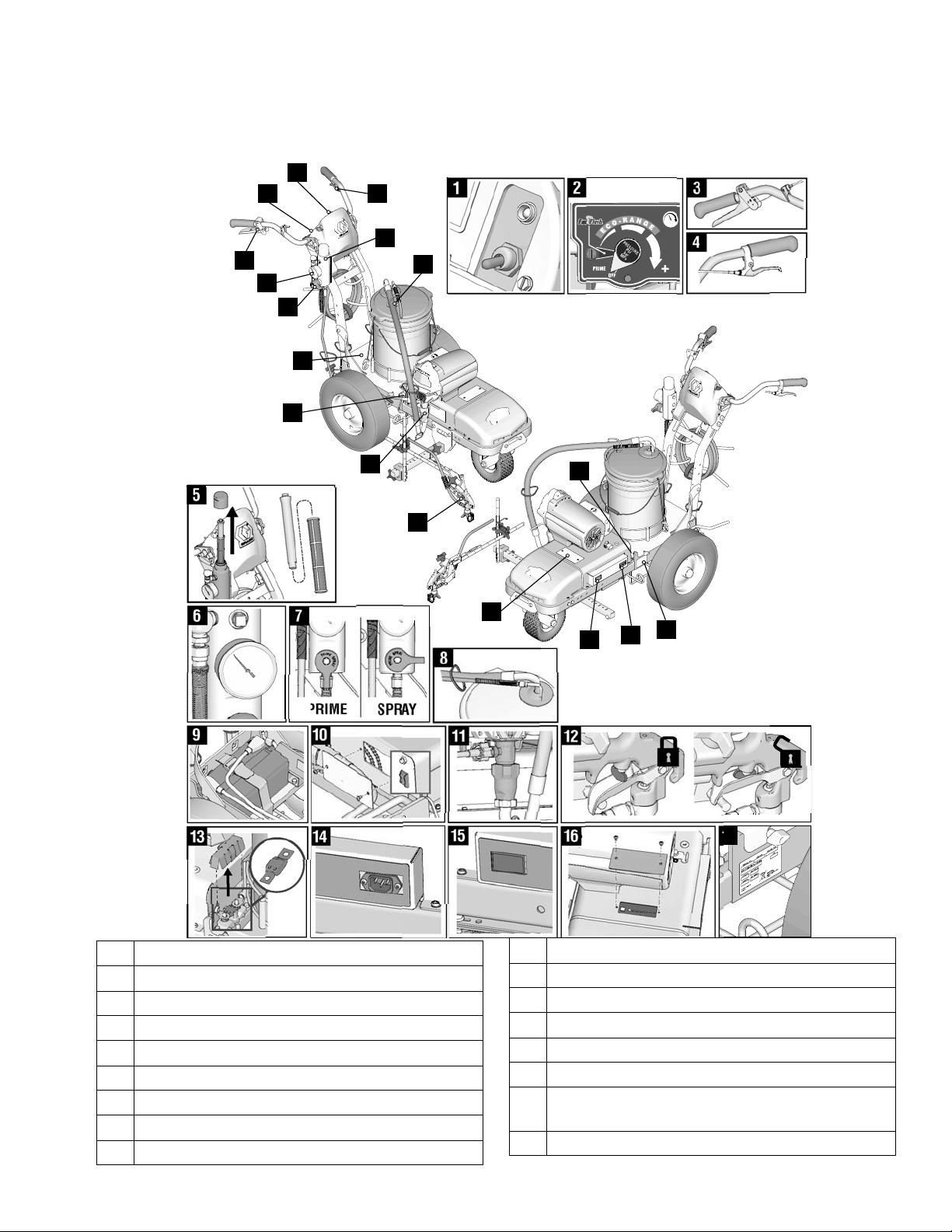
Component Identification (ES 1000)
1 ON/OFF Switch
2 Pressure Control & Display
3 Spray Gun Trigger
4 Turn Control
5 Filter
6 Pressure Gauge
7 Prime/Pressure Valves
8 Drain and Siphon Hoses
9 Battery Compartment
10 Inverter Circuit Breakers
11 Pump
12 Trigger Safety
13 Fuse
14 Charging Port
15 Voltage Meter
16 LED Status Center & Battery Type Selector
17 Serial ID
Access
3A4603F Operation, Repair, Parts 9
Page 10
Component Identification (ES 2000)
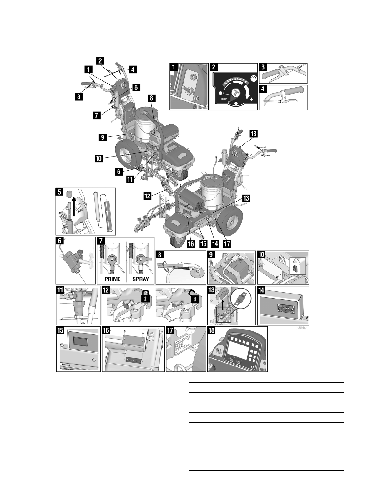
Component Identification (ES 2000)
1 ON/OFF Switch
2 Pressure Control & Display
3 Spray Gun Trigger
4 Turn Control
5 Filter
6 Laser
7 Prime/Pressure Valves
8 Drain and Siphon Hoses
9 Battery Compartment
10 3A4603F Operation, Repair, Parts
10 Inverter Circuit Breakers
11 Pump
12 Trigger Safety
13 Fuse
14 Charging Port
15 Voltage Meter
16 LED Status Center & Battery Type Selector
Access
17 Serial ID
18 Display
Page 11

Tip Selection
ti27606a
in.
in.
in.
in.
(cm)
ti27508a
ti27509a
Tip Selection
(cm)
ti27506a
(cm)
ti27505a
(cm)
LL5213* 2 (5)
LL5215* 2 (5)
LL5217
LL5219
LL5315
LL5317
LL5319
LL5321
LL5323
LL5325
LL5327
LL5329
LL5331
LL5333
LL5335
LL5355
4 (10)
4 (10)
4 (10)
4 (10)
4 (10)
4 (10)
4 (10)
4 (10)
4 (10)
4 (10)
4 (10)
4 (10)
4 (10)
4 (10)
LL5417 6 (15)
LL5419 6 (15)
LL5421 6 (15)
LL5423 6 (15)
LL5425 6 (15)
LL5427 6 (15)
LL5429 6 (15)
LL5431 6 (15)
LL5435 6 (15)
LL5621
LL5623
LL5625
LL5627
LL5629
LL5631
LL5635
LL5639
ti27507a
12 (30)
12 (30)
12 (30)
12 (30)
12 (30)
12 (30)
12 (30)
12 (30)
ti27510a
ti27605a
*Use 100 mesh filter to reduce tip clogs.
3A4603F Operation, Repair, Parts 11
Page 12
Battery and Charger
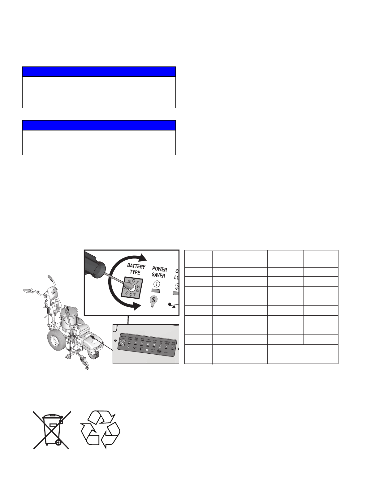
BATTERY TYPE SELECTOR SETTINGS
Switch
Position Description Boost/Vdc Float/Vdc
0 Charger Off
1 Gel USA 14.0 13.7
2 AGM 1 14.1 13.4
3 AGM 2
(Graco Supplied) 14.6 13.7
4 Sealed Lead Acid 14.4 13.6
5 Gel Euro 14.4 13.8
6 Open Lead Acid 14.8 13.3
7 LiFePO4 14.4 14.4
8 De-sulphation 15.5
(4 hours then Off)
9 Not used
ti30488a
Battery and Charger
NOTICE
If the battery level is below 9.7V, the on-board charger
will not be allowed to charge the battery. Charge battery
with an external charger to raise the level above 10.0V
to activate the on-board charger, or replace the battery.
NOTICE
Do not expose sprayer to rain or washdown. Exposure
could cause damage to electrical components. Store
and transport covered or indoors.
Battery Type and Charging Profiles
Graco recommends using a 12V 100 Ahr Absorbent
Glass Mat (AGM) DEEP CYCLE battery.The charger is
set for this charging profile from the factory. If a different
battery is used, the charging profile can be set at the
LED Status Center. The initial charge rate is 30 amps.
• Battery Protection Features: Unit is designed to
protect the battery by shutting down at 10.5V and
not allowing charging to occur above 15.5V.
• Self Discharge: Lead acid batteries can
self-discharge in as little as 3 months depending on
storage temperatures. The hotter the storage
temperature, the faster the self-discharge occurs.
To prevent damage to the battery, it is important to
keep the battery in a charged state.
• Battery Life: Battery recharge cycles depend on
the depth of discharge per cycle. A battery that is
discharged to 50% depth will get over twice as
many cycles in its life compared to it being
discharged to 100% depth each cycle.
Only use batteries that allow an initial charge rate of 30
amps or higher.
Use a small flat head screw driver to turn the arrow to
point at the number that correlates with the chosen
battery.
Battery Disposal
Do not place batteries in the trash. Recycle batteries according to local regulations.
12 3A4603F Operation, Repair, Parts
Page 13
Charging the Battery
ti30322a
ti30358a
ti30359a
ti30360a
Replace and charge battery only in well-ventilated
area and away from flammable or combustible
materials, including paints and solvents.
If the battery level is below 9.7V, the on-board charger
will not be allowed to charge the battery. Charge battery
with an external charger to raise the level above 10.0V to
activate the on-board charger, or replace the battery.
Use an extension cord with an undamaged ground
contact. If an extension cord is necessary, use a 3-wire,
12 AWG (2.5 mm
Batteries are fully charged when leaving the factory.
Due to self-discharging of the battery, charge battery
before first use. It takes ~3 hours to charge a dead
battery to 80%. It takes ~5 hours to charge a fully
depleted battery (double these times for 2 battery unit).
2
) minimum.
Battery and Charger
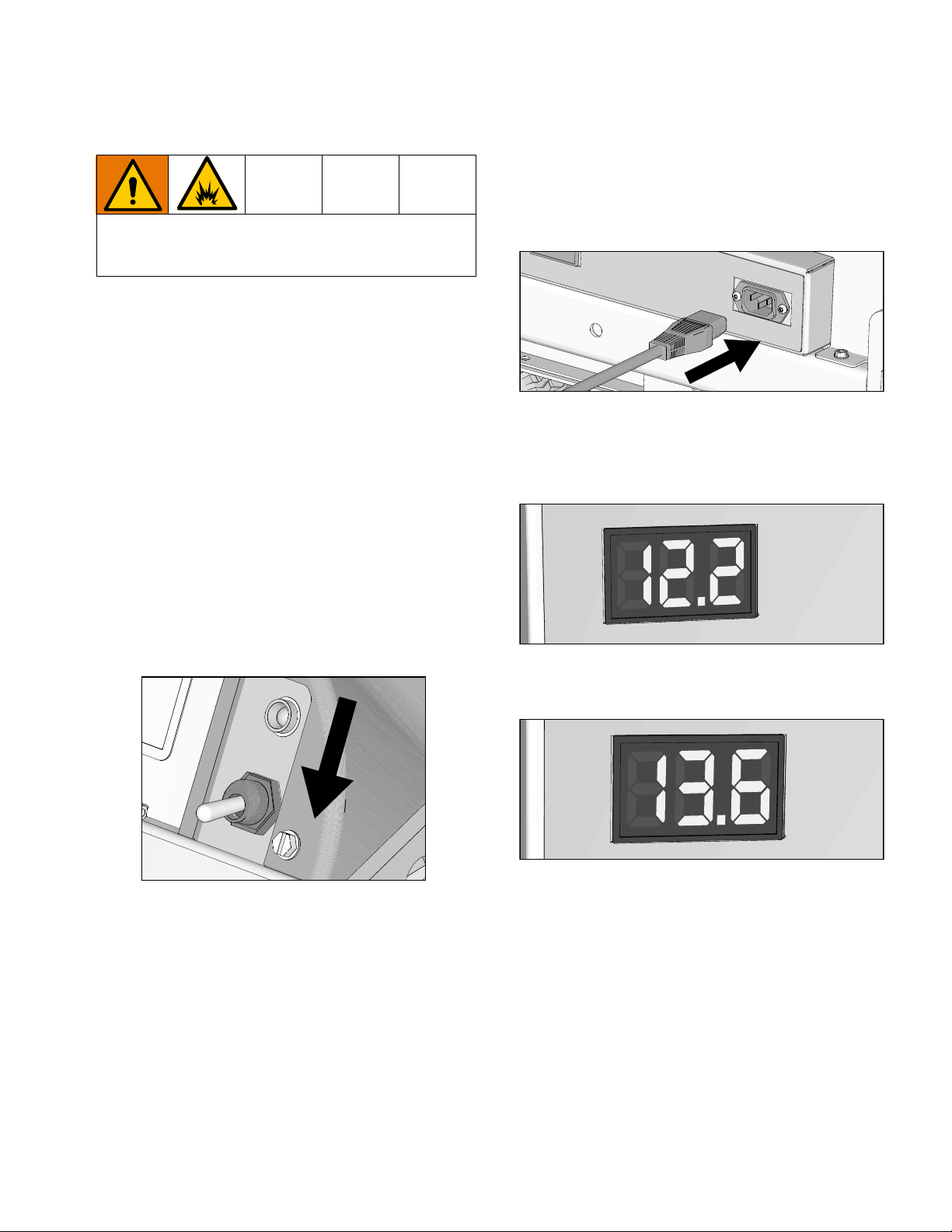
3. Plug charging cord into charging port on the unit.
Connect an extension cord, minimum 12AWG
(2.5mm
2
), to the charging cord and plug it into wall
power.
4. When power is connected the voltmeter will turn on
and the charger will immediately begin charging.
User should be able to see voltmeter start to climb
to indicate charging is occurring.
1. Place unit in dry, well-ventilated area and away from
flammable or combustible materials, including
paints and solvents.
2. Ensure power switch is in OFF position.
5. Battery will charge to 14.6-14.8 volts and then it will
come back down to ~13.6 volts when fully charged.
3A4603F Operation, Repair, Parts 13
Page 14
Grounding Procedure (AC Wall Power)
ti24584a
Grounding Procedure
(AC Wall Power)
This equipment must be grounded to reduce the risk
of static sparking and electric shock. An electric shock
or static spark can cause fumes to ignite or explode.
An improper ground can cause electric shock. A good
ground provides an escape wire for the electric
current.
Position the striper so the wheels are on a true
grounded surface. Not on pavement.
The plug must be plugged into an outlet that is properly
installed and grounded in accordance with all local
codes and ordinances.
Do not modify the plug provided; if it does not fit the
outlet, have the proper outlet installed by a qualified
electrician.
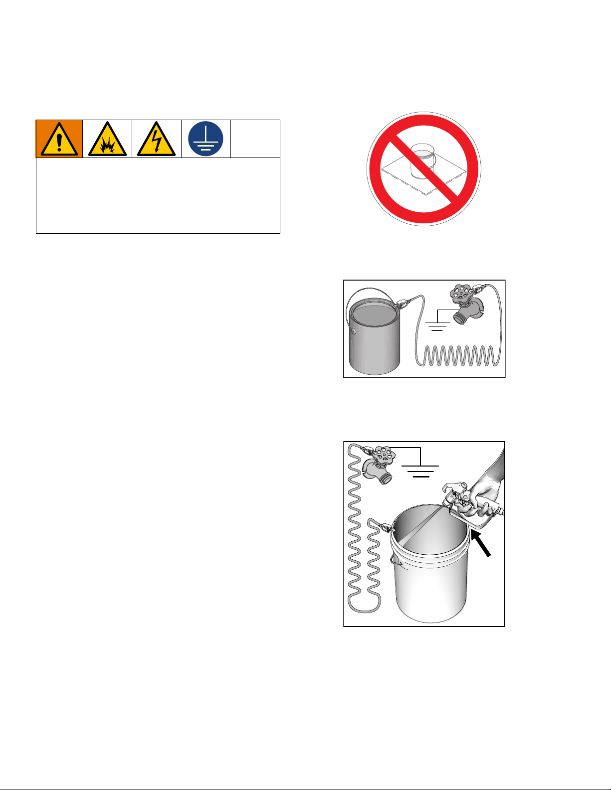
Do not place pail on a non-conductive surface such as
paper or cardboard which interrupts grounding
continuity.
Always ground a metal pail: connect a ground wire to
the pail. Clamp one end to the pail and the other end to
a true earth ground such as a water pipe.
Power Requirements
• 100-120V units require 100-120 VAC, 50/60 Hz, 12
or 15A, 1 phase.
• 230V units require 230 VAC, 50/60 Hz, 7 or 9A, 1
phase.
Extension Cords
Use an extension cord with an undamaged ground
contact. If an extension cord is necessary, use a 3-wire,
12 AWG (2.5 mm
2
) minimum.
Pails
Solvent and oil-based fluids: follow local code. Use
only conductive metal pails, placed on a grounded
surface such as concrete.
To maintain ground continuity when sprayer is
flushed or pressure is relieved: hold metal part of
spray gun firmly to the side of a grounded metal pail
then trigger gun.
ti24585a
14 3A4603F Operation, Repair, Parts
Page 15
Grounding Procedure (Battery Power) (For Flammable Flushing Fluids Only)
ti27615a
ti24584a
Grounding Procedure
(Battery Power) (For Flammable
Flushing Fluids Only)
This equipment must be grounded to reduce the risk
of static sparking. Static sparking can cause fumes to
ignite or explode. Grounding provides an escape wire
for the electric current.
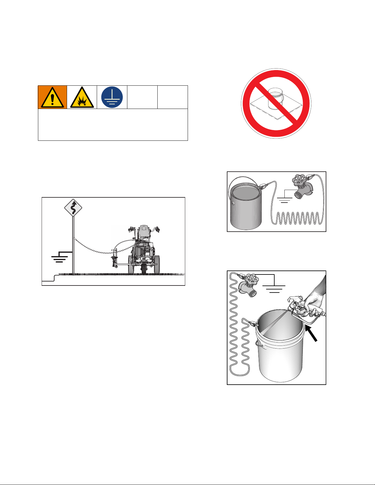
1. Position striper so that the tires are not on
pavement.
2. Striper is shipped with a grounding clamp.
Grounding clamp must attach to grounded object
(e.g., metal sign post).
Do not place pail on a non-conductive surface such as
paper or cardboard which interrupts grounding
continuity.
Always ground a metal pail: connect a ground wire to
the pail. Clamp one end to the pail and the other end to
a true earth ground such as a water pipe.
3. Disconnect grounding clamp after flushing is
complete.
Pails
Solvent and oil-based fluids: follow local code. Use
only conductive metal pails, placed on a grounded
surface such as concrete.
To maintain ground continuity when sprayer is
flushed or pressure is relieved: hold metal part of
spray gun firmly to the side of a grounded metal pail
then trigger gun.
ti24585a
3A4603F Operation, Repair, Parts 15
Page 16
Pressure Relief Procedure
ti30322a
ti27608a
Pressure Relief Procedure
This equipment stays pressurized until pressure is
manually relieved. To help prevent serious injury from
pressurized fluid, such as skin injection, splashing fluid
and moving parts, follow the
Procedure
when you stop dispensing and before
cleaning, checking, or servicing the equipment.
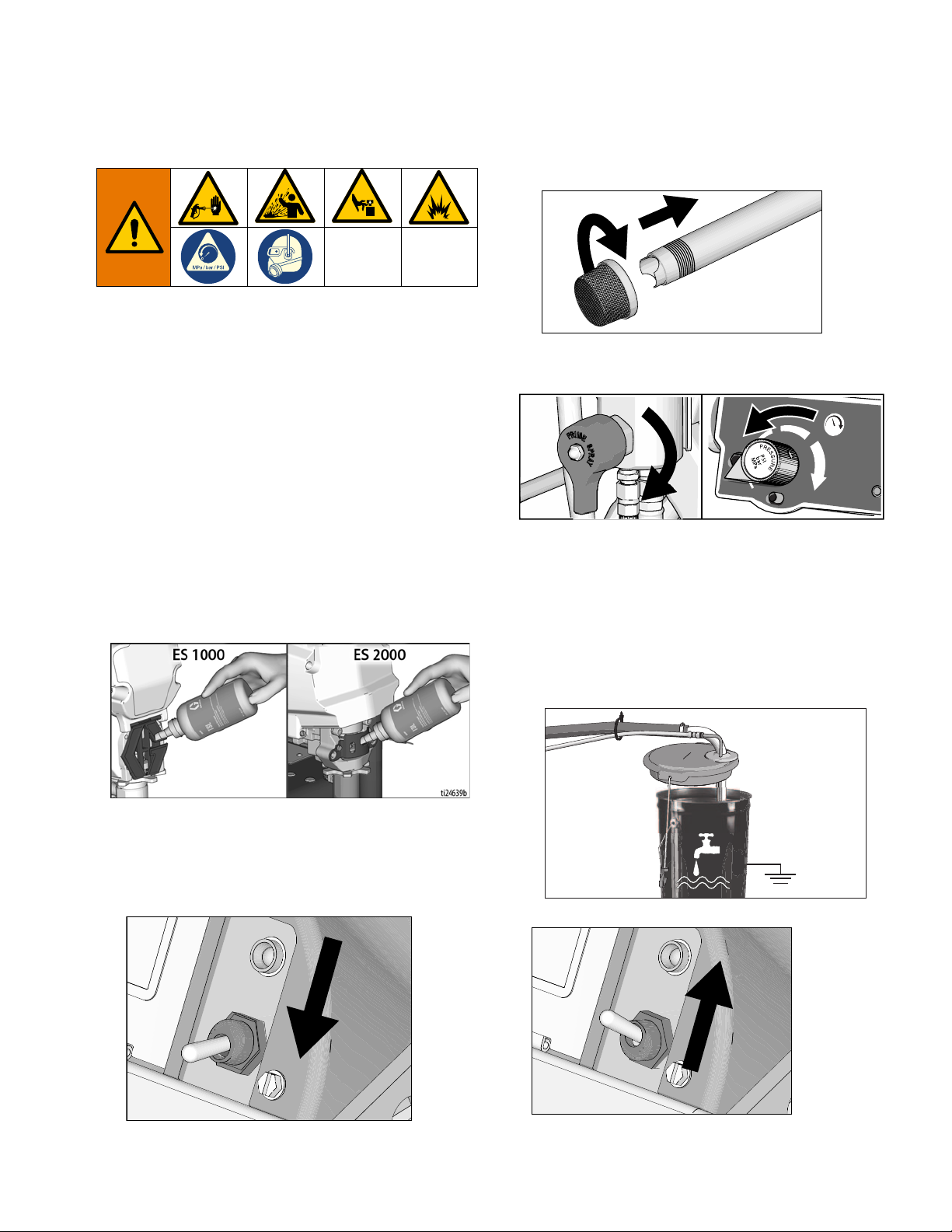
1. Perform Grounding Procedure if using flammable
materials.
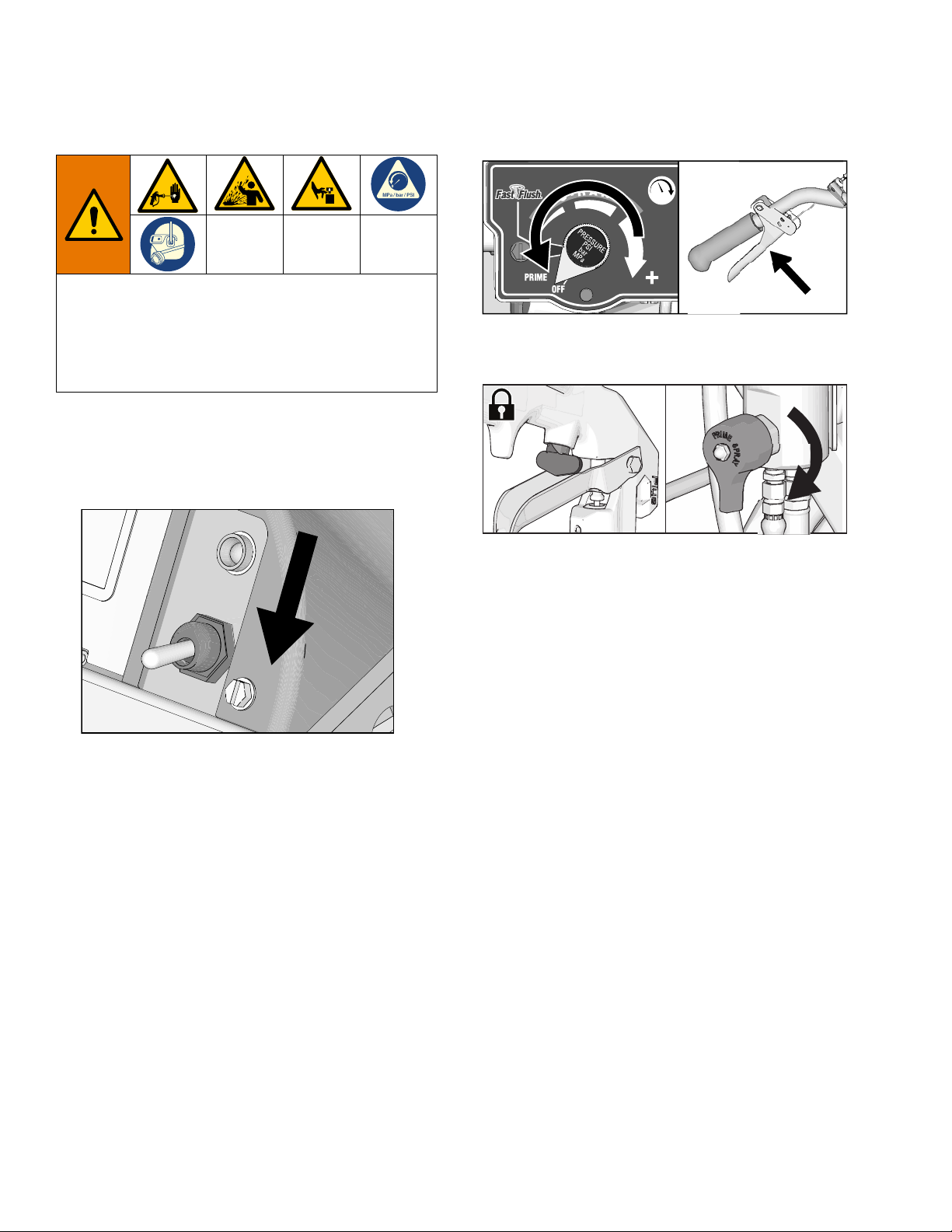
2. Turn ON/OFF Switch to OFF.
Pressure Relief
3. Turn pressure control to lowest setting. Trigger all
guns to relieve pressure.
ti30323a
4. Engage all gun trigger locks. Turn prime valve
down.
v
5. If you suspect the spray tip or hose is clogged or
that pressure has not been fully relieved:
a. VERY SLOWLY loosen the tip guard retaining
nut or the hose end coupling to relieve pressure
gradually.
b. Loosen the nut or coupling completely.
c. Clear the obstruction in the hose or tip.
16 3A4603F Operation, Repair, Parts
Page 17
Setup/Startup
ti30322a
ti27612a
ti27614a
ti30324a
Setup/Startup
6. If removed, install strainer.
1. Perform
Pressure Relief Procedure
, page 16
.
2. Charging the Battery, page 13.
3. Perform Grounding Procedure (AC Wall Power),
page 14, or Grounding Procedure (Battery
Power) (For Flammable Flushing Fluids Only),
page 15, if using flammable materials.
4. Fill throat packing nut with TSL to prevent
premature packing wear. Do this daily or each time
you spray.
a. Place the TSL bottle nozzle into the top center
opening in the grill at the front of the sprayer.
b. Squeeze bottle to dispense enough TSL to fill
the space between the pump rod and packing
nut seal.
7. Turn prime valve down. Turn pressure control
counterclockwise to lowest pressure.
NOTE: Minimum hose size for proper sprayer
operation is 1/4 in. x 50 ft for LL ES 1000 and 3/8 x 20’
for ES 2000.
8. Place siphon tube set in grounded metal pail
partially filled with flushing fluid. Attach ground wire
to true earth ground. Use water to flush water-based
paint and mineral spirits to flush oil-based paint and
storage oil.
NOTE: If running off wall power, plug cord into charging
port. If using an extension cord, use a 3-wire, 12 AWG
(2.5mm
5. Turn ON/OFF Switch to OFF.
2
) minimum with an undamaged ground contact.
ti27613a
9. Turn ON/OFF Switch to ON:
3A4603F Operation, Repair, Parts 17
Page 18
Setup/Startup
ti27771a
ti30349a
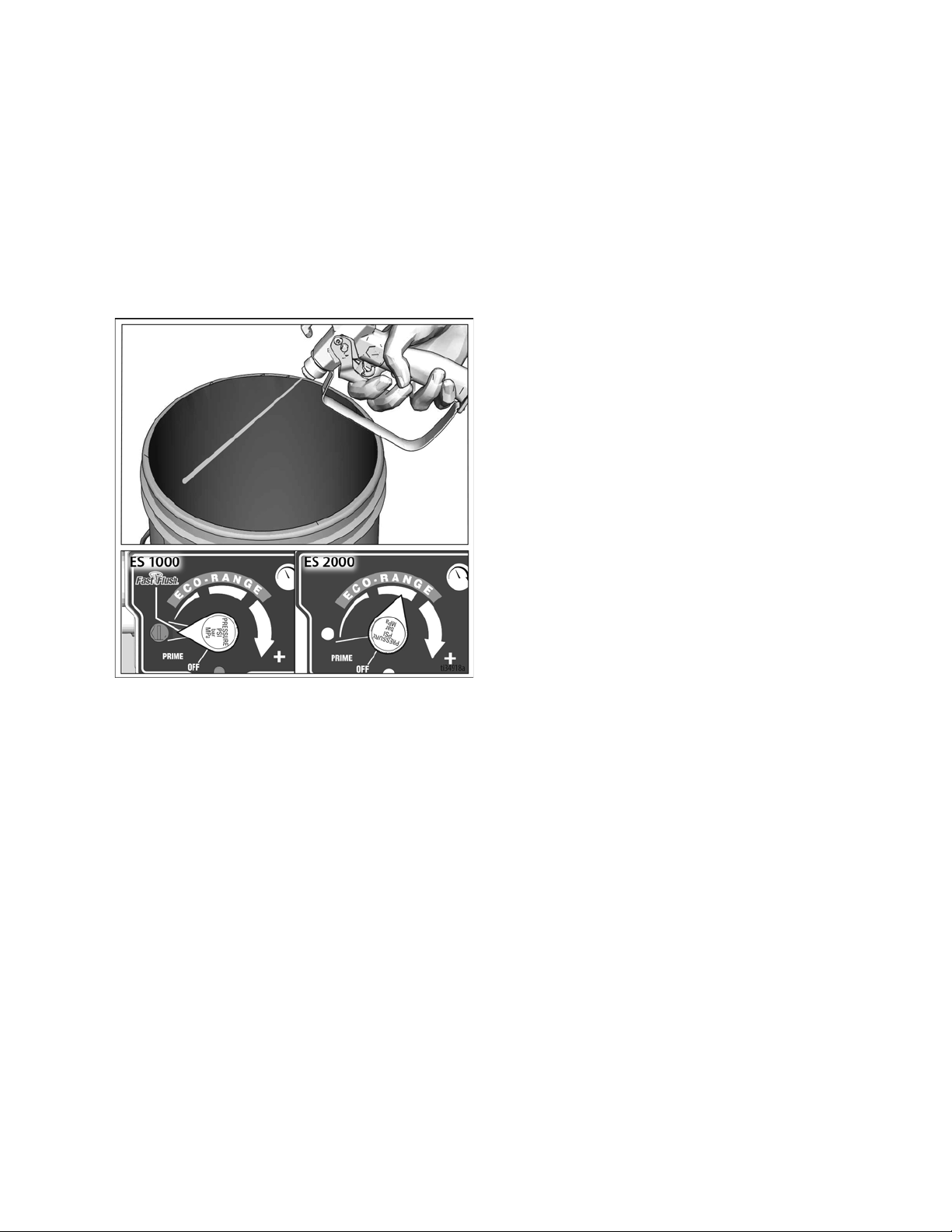
10. ES 1000: Turn pressure control to prime. Allow fluid
to circulate for 15 seconds.
ES 2000: Increase pressure 1/2 turn to start motor
and allow fluid to circulate for 15 seconds.
11. Turn pressure down, turn prime valve horizontal.
Disengage gun trigger lock.
12. Hold all guns against a grounded metal flushing pail.
Trigger guns and increase fluid pressure slowly until
pump runs smoothly to spray.
13. Inspect fittings for leaks. If leaks occur, turn sprayer
OFF immediately. Perform
Procedure
Setup/Startup
, page 16. Tighten leaky fittings. Repeat
, steps 1 - 13. If no leaks, continue to
Pressure Relief
trigger gun until system is thoroughly flushed.
Proceed to step 14.
14. Place siphon tube in paint pails.
ti27613a
15. Trigger all guns again into a flushing fluid pail until
paint appears. Assemble tips and guards.
High-pressure spray is able to inject toxins into the
body and cause serious bodily injury. Do not stop
leaks with hand or rag.
ti27774a
16. ES 2000: Digital display is functional when unit is
turned on.
18 3A4603F Operation, Repair, Parts
Page 19
SwitchTip and Guard Assembly
ti27775a
ti27776a
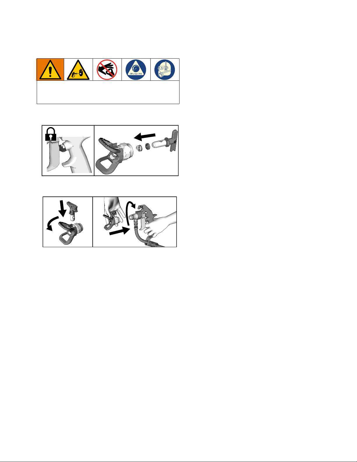
To avoid serious injury from skin injection do not put
your hand in front of the spray tip when installing or
removing the spray tip and tip guard.
1. Engage trigger lock. Use end of SwitchTip to press
OneSeal into tip guard, with curve matching tip bore.
2. Insert SwitchTip in tip bore and firmly thread
assembly onto gun.
Setup/Startup
3A4603F Operation, Repair, Parts 19
Page 20
Gun Placement
ti27777a
ti27778a
ti28129a
ti28130a
1
2
ti27781a
ti27782a
ti27782a
Gun Placement
Install Gun
1. Insert guns into gun holder. Tighten clamps.
Position Gun
2. Position gun: up/down, forward/reverse, left/right.
See Gun Positions Chart, page 22 for examples.
Another option can be to swing the gun out at an angle
and rotate the tip guard. This results in better visibility
for the user.
Select Manual Guns
3. Connect gun cables to left or right gun selector
plates.
NOTE: When striping above a curb, the mounting clamp
can be rotated for clearance.
ti27780a
a. One gun: Disconnect one gun selector plate
from trigger.
b. Both guns simultaneously: Adjust both gun
selector plates to the same position.
c. Solid-skip and skip-solid: Adjust solid-line gun
to position 1 and skip-line to position 2.
20 3A4603F Operation, Repair, Parts
Page 21
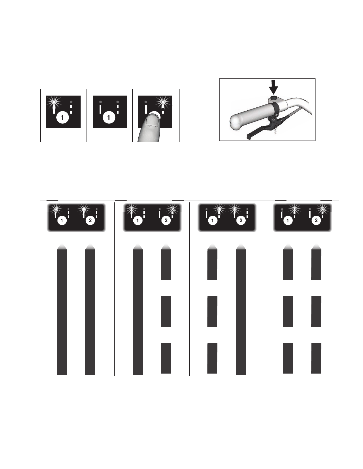
Select Auto Guns (ES 2000)
1s
ti27784a
ti27881a
ti27785a
Gun
1
Gun
2
Gun
1
Gun
2
Gun
1
Gun
2
Gun
1
Gun
2
Gun Placement
1. Use the gun selector buttons to determine which
guns are active. Each gun selector has 3 settings:
continuous line, OFF and programmed line pattern.
2. Use the gun trigger control to actuate auto guns.
4 Examples:
3A4603F Operation, Repair, Parts 21
Page 22
Gun Placement
1
2
3
4
5
6
7
ti27786a
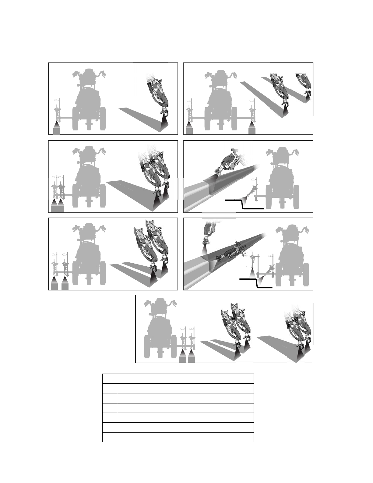
Gun Positions Chart
1 One line
2 One line up to 24 in. (61cm) wide
3 Two lines
4 One line or two lines to spray around obstacles
22 3A4603F Operation, Repair, Parts
5 One gun curb
6 Two gun curb
7 Two lines or one line up to 24 in. (61 cm) wide
Page 23
Gun Placement
ti30326a
ti27796c
ti30327a
ti27797a
ti30328a
ti30329a
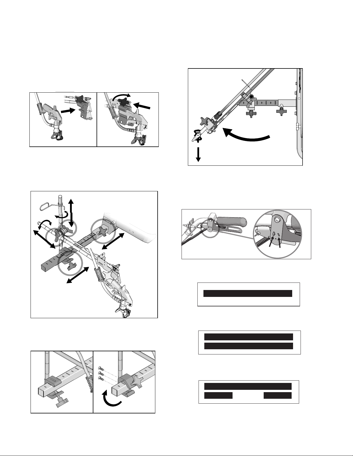
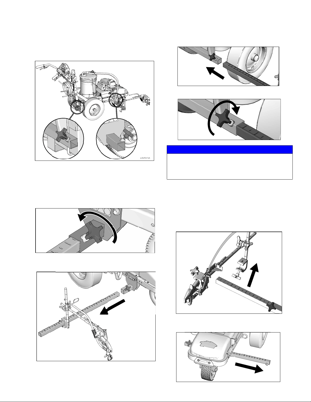
Gun Arm Mounts
This unit is equipped with front and rear gun arm
mounts.
Change Gun Position
(Front and Back)
3. Slide gun arm assembly into desired gun arm
mounting slot.
4. Tighten gun arm knob into gun arm mounting slot.
ti27798a
NOTICE
Make sure all hoses, cables, and wires are properly
routed through brackets and do NOT rub on tire.
Contact with tire will result in damaged hoses, cables,
and wires.
Change Gun Position
1. Loosen gun arm knob and remove from gun arm
mounting slot.
2. Slide gun arm assembly (including gun and hoses)
out from gun arm mounting slot.
(Left and Right)
Removal
1. Loosen vertical gun arm knob on gun arm mounting
bar and remove.
2. Extend mounting bar on opposite side of the
machine.
3A4603F Operation, Repair, Parts 23
Page 24
Gun Placement
ti27801a
ES 2000
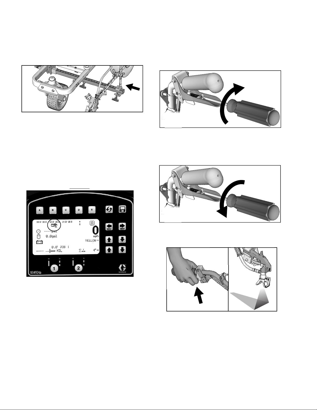
Installation
1. Install vertical gun mount onto gun bar.
NOTE: Make sure all hoses, cables, and wires are
properly routed through brackets.
Trigger Sensor Adjustment (ES
2000)
1. Turn striper on. Engage trigger. Spray icon should
appear simultaneously with start of fluid spray.
No fluid spray
2. Turn screw in handle clockwise if spray icon
appears before fluid spray starts.
ti27802a
No spray icon
3. Turn screw in handle counterclockwise if fluid spray
starts before spray icon appears.
ti27803a
4. Continue adjusting screw in handle until timing of
spray icon and fluid spray are synchronized.
Adjustment of the gun cables might be necessary.
ti27883a
24 3A4603F Operation, Repair, Parts
Page 25
Gun Placement
ES 1000 & ES 2000
ES 2000
ti27805b
ti27806b
ti27807b
ti27809a
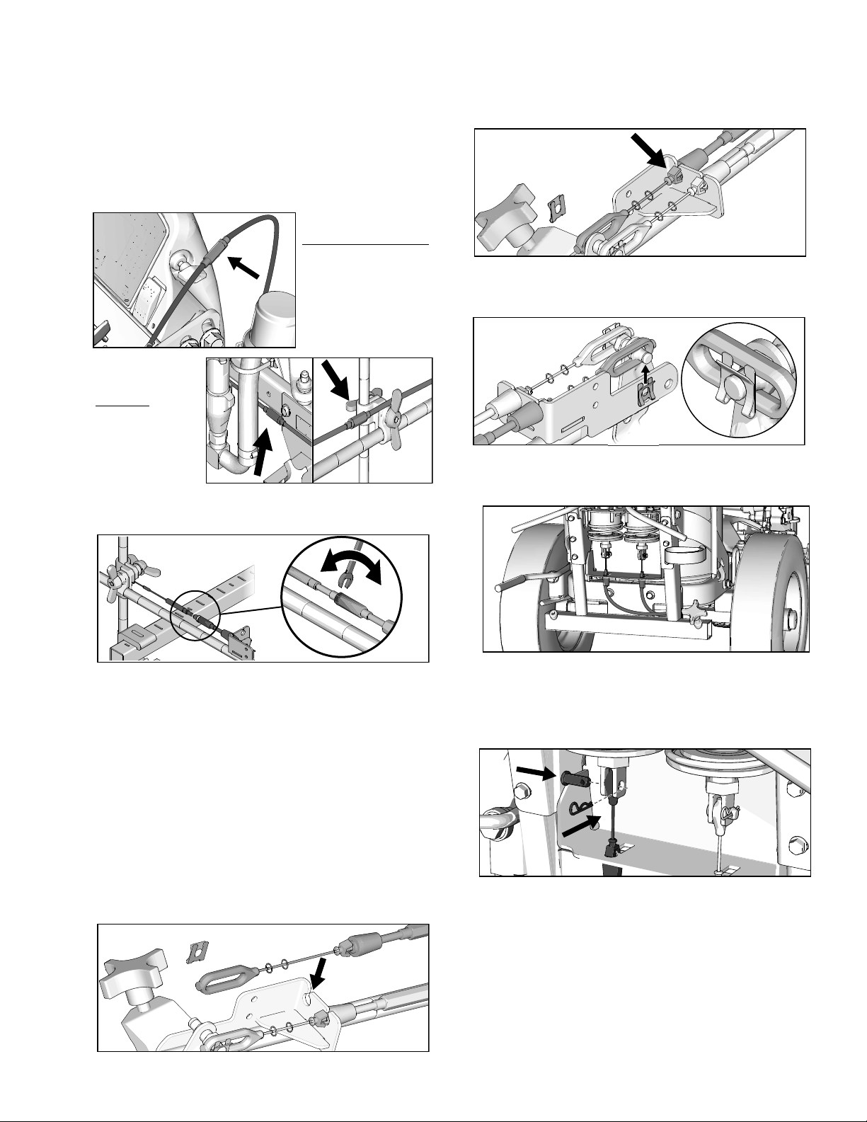
Gun Cable Adjustment
Adjusting the gun cable will increase or decrease the
gap between the trigger plate and the gun trigger. To
adjust trigger gap, perform the steps below.
ti27884a
ti27885a
1. Use wrench to loosen locking nut on cable adjuster.
3. Insert plastic cable retainer into cable bracket hole.
4. Install cable end onto trigger plate pin and install
clip.
5. Route cable around unit and up through cable holes
behind hose mount.
ti27804a
2. Loosen or tighten adjuster until desired result is
achieved. NOTE: More thread exposed means less
gap between gun trigger and trigger plate.
3. Use wrench to tighten locking nut on the adjuster.
Adding Gun Cable (ES 2000)
The ES 2000 can be equipped with two gun actuators.
Each gun actuator is capable of operating one cable.
1. Select cable end with adjuster.
2. Install exposed cable through cable bracket slot.
ti27808a
6. Route cable end loop through rectangular hole in
bracket and insert plastic cable retainer into the
actuator bracket. Install cable end onto actuator rod
and install pin.
3A4603F Operation, Repair, Parts 25
Page 26
Gun Placement
ti27810a
ti27811a
ti27812a
ti27813a
ti27814a
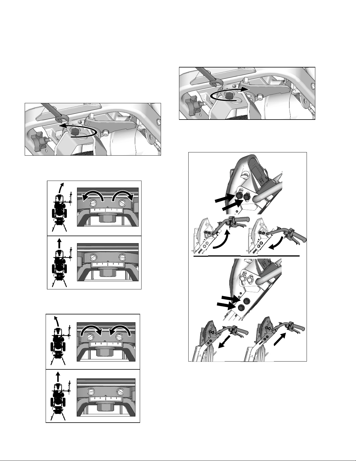
Straight Line Adjustment
The front wheel is set to center the unit and allow the
operator to form straight lines. Over time, the wheel may
become misaligned and will need to be readjusted. To
re-center the front wheel, perform the following steps:
1. Loosen bolt on the front wheel bracket.
2. If striper arcs to the right, loosen left set screw and
tighten right set screw for fine tune adjustment.
4. Roll the striper. Repeat steps 2 and 3 until striper
rolls straight. Tighten bolt on wheel alignment plate
to lock the new wheel setting.
Handle Bar Adjustment
3. If striper arcs to the left, loosen right set screw and
tighten left set screw.
26 3A4603F Operation, Repair, Parts
Page 27
Paint Stripe Width
ti30078a
ti30103a
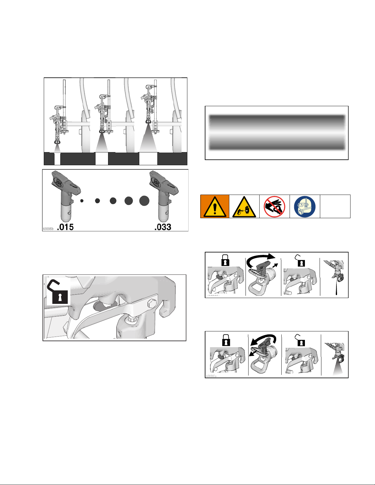
Paint Stripe Width
1. Adjust gun up or down to change paint stripe width.
ti30304a
Spray Test Stripe
2. Trigger gun and spray test pattern. Slowly adjust
pressure to eliminate heavy edges. Use smaller tip
size if pressure adjustment can not eliminate heavy
edges.
Clearing Tip Clogs
1. Release trigger. Engage gun trigger lock. Rotate
SwitchTip. Disengage gun trigger lock and trigger
gun to clear the clog.
1. Disengage trigger lock.
ti30306a
2. Engage gun trigger lock, return SwitchTip to original
position, disengage gun trigger lock and continue
spraying.
3A4603F Operation, Repair, Parts 27
Page 28
Cleanup
TI3371A
ti6269a
FLUSH
TI3375A
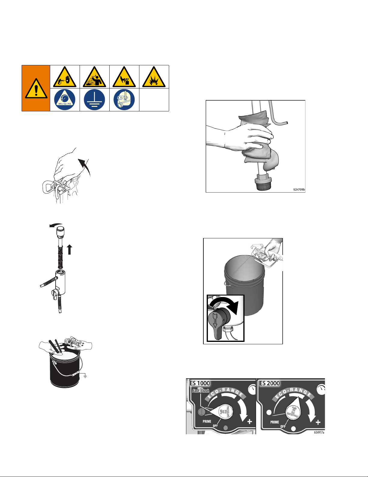
Cleanup
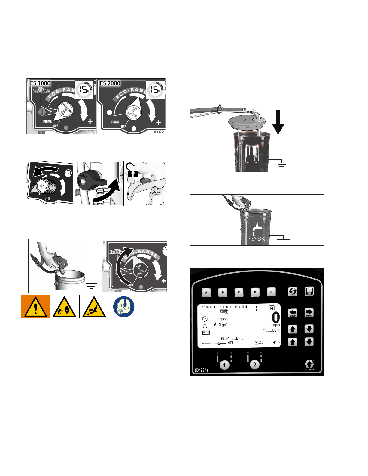
1. Perform Pressure Relief Procedure, page 16.
2. Remove guard and SwitchTip from all guns.
Flush Drain Tube
6. Remove fluid intake and drain tube from paint, wipe
excess paint off outside.
3. Unscrew cap, remove filter. Assemble without filter.
4. Clean filter, guard and SwitchTip in flushing fluid.
7. Place siphon tube set in grounded metal pail
partially filled with flushing fluid. Use water for water
base paint and mineral spirits for oil-based paint.
8. To flush drain tube and pump turn prime valve down.
ti24713a
9. Turn pressure control to Fast Flush (ES1000), or 1/2
position (ES2000), and operate until the pump runs
steady and flushing fluid appears in the waste pail.
5. Attach ground wire to true earth ground or plug unit
into grounded outlet.
28 3A4603F Operation, Repair, Parts
Page 29
Flush Hose and Gun
Cleanup
10. To flush airless hose and spray gun, turn prime
valve horizontal.
11. Hold gun against waste pail. Disengage trigger lock.
Trigger gun and turn pressure control to Fast Flush
(ES1000), or 1/2 position (ES2000), and operate
until the pump runs steady and flushing fluid
appears.
12. Stop triggering gun.
13. Fill pump with Pump Armor and reassemble filter,
guard and SwitchTip.
14. Each time you spray and store, fill throat packing
nut with TSL to decrease packing wear.
3A4603F Operation, Repair, Parts 29
Page 30
LineLazer V LiveLook Display
LineLazer V LiveLook Display
ES 2000 (Standard Series)
30 3A4603F Operation, Repair, Parts
Page 31

Initial Setup (ES 2000 Standard Series)
ti27828a
26 Ft.
8M
ti27829a
LineLazer V LiveLook Display
The initial setup prepares the striper for operation based
on a number of user entered parameters. Language
selections and the units of measure selections can be
set before you start or changed later.
Language
From Setup/Information select appropriate language by
pressing until the language is outlined.
US Units
Pressure = psi
Volume = gallons
Distance = feet
Line Thickness = mil
SI Units
Pressure = bar (MPa available)
Volume = liters
Distance = meters
Line thickness = micron (g/m
Paint Specific Gravity = Use UP and DOWN arrows
to set specific gravity. Required to determine paint
thickness.
NOTE: All units can be changed individually at any
time.
2
available)
Calibration
1. Check rear tire pressure 55 ± 5 psi (379 ± 34 kpa)
and fill if necessary.
2. Extend steel tape to distance greater than 26 ft.
(8m).
ENG = English
SPA = Spanish
FRE = French
DEU = German
RUS = Russian
WORLD = Symbols see World Key Symbol, page
113.
NOTE: Language can be changed later.
Units
Press to enter settings and then again to enter
units. Select appropriate units of measure.
3A4603F Operation, Repair, Parts 31
Page 32

LineLazer V LiveLook Display
ti27827a
ti27830a
1 FT 2 FT 3 FT 4 FT 5 FT 6 F
ti27831a
26 FT 27 FT 28 FT 29 FT 30 FT 31 F25 FT
ti27832a
3. Press to select Setup/Information.
4. Press for Calibration. Set TRAVEL DIST to 25 ft
(7.6m) or longer. Longer distances ensure better
accuracy, depending on conditions.
\
6. Push to start calibration.
ti27826a
7. Move striper forward. Keep unit aligned with steel
tape.
8. Stop when chosen part of unit aligns with 26-ft (8m),
or distance entered, on steel tape (25-ft./ 7.6m distance).
5. Align part of the unit with 1 foot (30.5cm) on steel
tape.
9. Push to complete calibration.
ti27941a
• Calibration is not complete when the exclamation
symbol is displayed.
• Calibration is finished when the check mark symbol
is displayed.
10. Calibration is now complete.
Go to Measure Mode (ES2000 Standard Series), page
34, and verify accuracy by measuring the tape.
32 3A4603F Operation, Repair, Parts
Page 33

Striping Mode (ES2000 Standard Series)
ti27890a
LineLazer V LiveLook Display
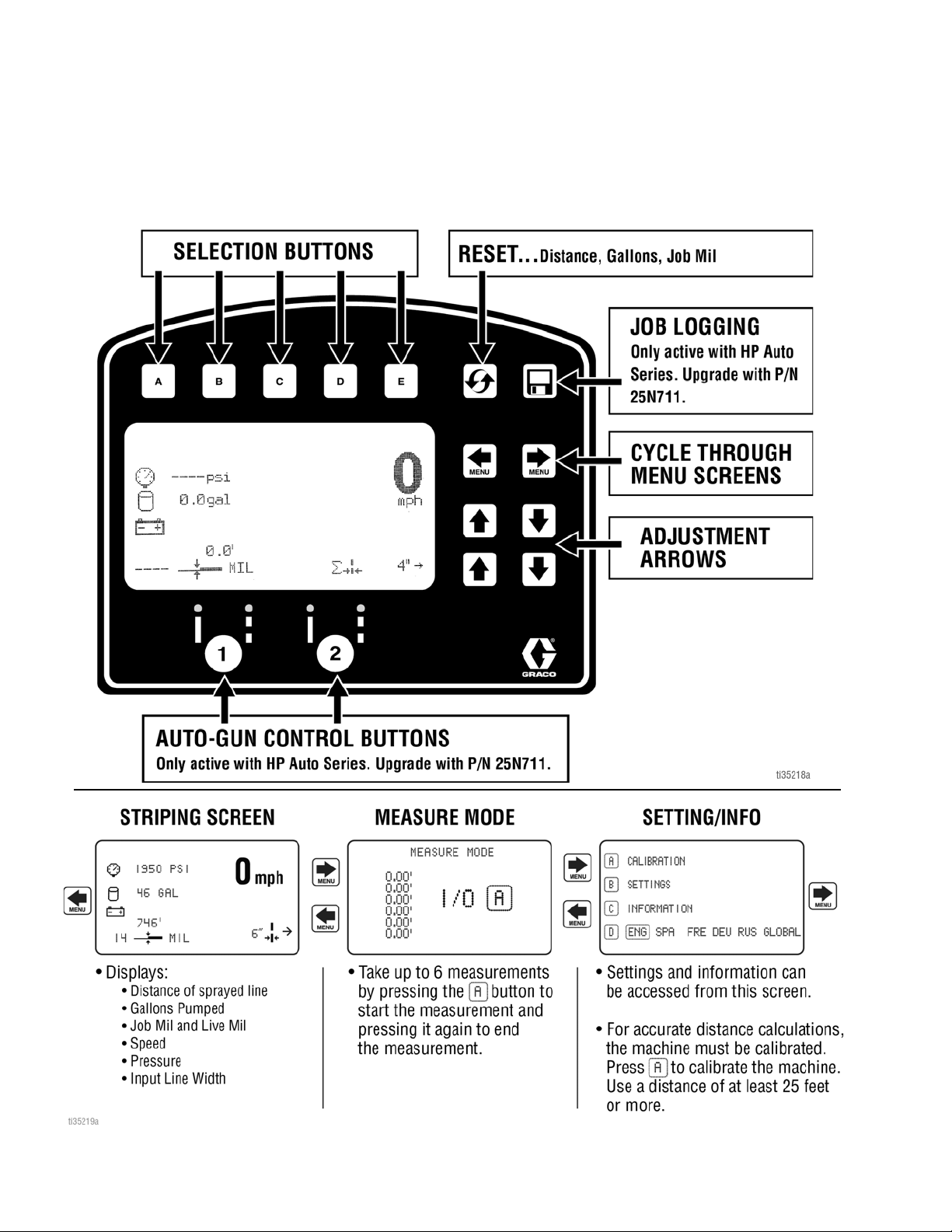
Ref. Description
1 Resets Distance, Gallons, Mils
*2 Job logging
3 Scroll between menu screens
4 Line width adjustment buttons
*5 Auto gun buttons
6 MIL thickness. While spraying “Instant MIL avg” is
displayed. When stopped total “Job MIL avg” is
displayed.
7 Total gallons sprayed
8 Total line length sprayed.
9 Pressure
* Not active in Standard Series. Upgrade to HP Auto
Series with P/N 25N711.
Operating in Striping Mode
1. Make sure ON/OFF switch is ON position.
2. Set pump switch to ON.
3. Pull trigger to spray.
3A4603F Operation, Repair, Parts 33
Page 34

LineLazer V LiveLook Display
ti27834a
1 2
3
4
Measure Mode (ES2000 Standard Series)
Measure Mode replaces a tape measure to measure
distances when laying out an area to be striped.
1. Use to select Measure Mode.
Ref. Description
2. Press and release . Move striper forwards or
backwards. (Moving backwards is a negative distance.)
3. Press and release to end measured length. Up
to six lengths are viewable.
1 Press to start measurement, Press to stop
measurement
2 Hold to reset values to zero
3 Scroll between main menu screens
4 Last measurement taken
34 3A4603F Operation, Repair, Parts
Page 35

Setup/Information
ti27835b
Use to select Setup/Information.
LineLazer V LiveLook Display
Press to select Language.
See Language, page 31.
See Calibration, page 31.
See Settings, page 36.
See Information, page 37.
3A4603F Operation, Repair, Parts 35
Page 36

LineLazer V LiveLook Display
Settings
Use to select Setup/Information. Press to
open Settings Menu.
Chooses the machine type. Necessary for accurate
gallon counting.
Use to set time and date.
Use
Set units with
Use to adjust screen contrast to the desired
value.
36 3A4603F Operation, Repair, Parts
Page 37

Information
Stroke Counter
Pressure Transducer
Distance Sensor
Touch Pad Buttons
Battery Voltage
Use to select Setup/Information. Press to
open Information Menu.
LineLazer V LiveLook Display
Displays and logs life data and striper information.
View and test functionality of components.
Logs last four error codes that occurred.
Code Description
02 = Over pressure
03 = No transducer detected
Reset error codes
3A4603F Operation, Repair, Parts 37
Page 38

ES2000 (HP Auto Series)
ES2000 (HP Auto Series)
38 3A4603F Operation, Repair, Parts
Page 39

LineLazer V LiveLook Display
ES2000 (HP Auto Series)
LineLazer V LiveLook Display
3A4603F Operation, Repair, Parts 39
Page 40

LineLazer V LiveLook Display
ti27827a
ti27828a
26 Ft.
8M
ti27829a
Initial Setup (ES2000 HP Auto Series)
The initial setup prepares the striper for operation based
on a number of user entered parameters. Language
selections and the units of measure selections can be
set before you start or changed later.
Language
From Setup/Information select appropriate language by
pressing until the language is outlined.
US Units
Pressure = psi
Volume = gallons
Distance = feet
Line Thickness = mil
SI Units
Pressure = bar (MPa available)
Volume = liters
Distance = meters
Line thickness = micron (g/m
2
available)
Paint Specific Gravity = Use UP and DOWN arrows
to set specific gravity. Required to determine paint
thickness.
NOTE: All units can be changed individually at any
time.
Calibration
1. Check rear tire pressure 55 ± 5 psi (379 ± 34 kpa)
and fill if necessary.
2. Extend steel tape to distance greater than 26 ft.
(8m).
ENG = English
SPA = Spanish
FRE = French
DEU = German
RUS = Russian
WORLD = Symbols see World Key Symbol, page
113.
NOTE: Language can be changed later.
Units
Press to enter settings and then again to enter
units. Select appropriate units of measure.
40 3A4603F Operation, Repair, Parts
Page 41

LineLazer V LiveLook Display
ti27827a
ti27830a
ti27841a
ti27912a
ti27843a
ti27912a
3. Press to select Setup/Information.
4. Press for Calibration. Set TRAVEL DIST to 25 ft
(7.6m) or longer. Longer distances ensure better
accuracy, depending on conditions.
6. Press and release gun trigger control to start calibration.
7. Move striper forward. Keep laser dot on steel tape.
8. Stop when laser aligns with 26-ft (8m) or distance
entered on steel tape (25-ft./7.6m distance).
5. Turn on laser and align laser dot with 1 foot
(30.5cm) on steel tape.
9. Press and release gun trigger control to complete
calibration.
• Calibration is not complete when the exclamation
symbol is displayed.
• Calibration is finished when the check mark symbol
is displayed.
10. Calibration is now complete.
3A4603F Operation, Repair, Parts 41
Page 42

LineLazer V LiveLook Display
ti27881a
Striping Mode (ES2000 HP Auto Series)
Ref. Description
Select a “Favorite”, press for less than one sec-
ond.
1
Save a “Favorite”, press and hold for more than
three seconds.
2 Cycles between viewing line width or paint and
space value.
Cycles between Manual Mode, Semi-Automatic
Mode, Automatic Mode.
Manual Mode : Press and hold gun trigger
control to stripe.
Semi-Automatic Mode : Press and release
3
gun trigger control to stripe the programmed
length one time when in Skip Mode.
Automatic Mode : Press and release gun
trigger control to start striping. Press and release
button again to stop.
4 Resets trip distance.
5 Job Data Logger, page 52.
6 Scrolls between menu screens.
7 Paint and Space length OR line width adjustment
buttons.
8 Auto guns activation buttons.
9 MIL thickness. While spraying “Instant MIL avg” is
displayed. When stopped total “Job MIL avg” is
displayed.
10 Total gallons (liters) sprayed.
11 Total line length sprayed.
12 Pressure
Operating in Striping Mode
Striper must be running before activating gun trigger
control.
1. Make sure ON/OFF switch is ON position.
2. Use gun activation buttons to select guns and line
type.
ti27913a
3. Press gun trigger control to begin spraying.
In Automatic Mode or Semi-Automatic Mode the or
will flash when gun trigger control is pressed to sig-
nal mode is active.
42 3A4603F Operation, Repair, Parts
Page 43

Measure Mode (ES2000 HP Auto Series)
ti27914a
2 3
5
4
1
ti27842a
ti27915a
ti27842a
LineLazer V LiveLook Display
Measure Mode replaces a tape measure to measure
distances when laying out an area to be striped.
1. Use to select Measure Mode.
2. Press and release gun trigger control. Move striper
forwards or backwards. (Moving backwards is a
negative distance.)
3. Press and release gun trigger control to end measured length. Up to six lengths are viewable.
The most recent measured length is also saved as the
measured distance in the Stall Calculator display. See
Stall Calculator, page 45.
If an auto gun is activated, press and hold gun trigger
control at any time to apply a dot. If trigger is held while
striper is moving, a dot is marked every 12-inches
(30.5cm).
Ref. Description
1 Press to start measurement, Press to stop
measurement.
2 Hold to reset values to zero.
3 Job Data Logger, page 52.
4 Scroll between main menu screens
5 Last measurement taken
3A4603F Operation, Repair, Parts 43
Page 44

LineLazer V LiveLook Display
5
6
7
ti27912a
ti27849a
Layout Mode
Layout Mode is used to calculate and mark parking lot
stalls.
1. Use to select Layout Mode.
192 34
8
Ref. Description
ti27916a
2. Use gun activation buttons to select guns.
ti27918a
3. Press and release gun trigger control and move
striper forward.
4. Striper default is to place a dot every 9.0 ft (2.7m) to
mark the stall size. Stall size is adjustable.
5. Dots are laid down until gun trigger control is
pressed and released again.
1 Opens Stall Calculator Menu.
See Stall Calculator, page 45.
2 Opens Angle Calculator Menu.
See Angle Calculator, page 46.
Select a “Favorite”, press for less than one
3
second.
Save a “Favorite”, press and hold for more than
three seconds.
4 Job Data Logging, page 52.
5 Scroll between menu screens.
6 Adjust stall size/dot spacing.
7 Adjust dot size.
8 Auto Gun activation buttons.
9 Pressure.
An indicator on the screen alternately flash when gun
trigger control is pressed to signal mode is active.
44 3A4603F Operation, Repair, Parts
Page 45

LineLazer V LiveLook Display
Stall Calculator
Stall Calculator is used to set the stall size. The striper
divides the measured length by the stall size to
determine the number of stalls that will fit in the length
measured. User can adjust number of stalls to a round
number and stall width is calculated.
1. Use to select Layout Mode. Press to
open Stall Calculator Menu.
2. The most recent length measured in Measure Mode
is automatically displayed. Press gun trigger control
to start a new measurement. Press again to stop
measuring.
When measuring between curbs, the distance from
the back tire/curb to the gun/laser dot, can be
accounted for by setting the Offset (x) value.
a. Back the striper up to the curb, then use a tape
measure to measure from where the tire touches
the curb to the laser dot on the ground.
b. Use to enter the offset (x) value.
c. This value can be stored by holding for 2
seconds.
d. The value stored under can be added to the
measured distance before or after the
measurement is taken between the curbs.
e. The offset (x) value can also be adjusted before or
after the measurement is taken by using .
Stall size and calculated number of stalls are both
adjustable.
Ref. Description
1 Opens Angle Calculator Menu.
See Angle Calculator, page 46.
2 Exits and returns stall size to Layout Mode.
3 Measured distance.
4 Calculated # of stalls. Changing the number of
stalls will change the stall size.
5 Adjusts number of stalls.
6 Stall size. Changing stall size changes the
calculated # of stalls.
7 Adjusts stall size.
8 Press to start measurement, Press to stop
measurement.
9 Adjust Offset (x).
10 Stores Offset (x). Hold for 2 seconds to store
value.
3. Press to return to Layout Mode. The Stall size
is saved and displayed on the Layout Mode screen.
4. Press and release gun trigger control to start
marking dots. Press and release gun trigger control
again to stop.
3A4603F Operation, Repair, Parts 45
Page 46

LineLazer V LiveLook Display
1
7
8
2 3 4
5
6
ti27850a
STALL
SIZE
LINE
LENGTH
B
C
STALL
DEPTH
OFF SET
ANGLE
DOT SPACING
ti27857a
Angle Calculator
Angle Calculator is used to determine the offset value
and dot spacing value for a layout.
1. Use to select Layout Mode. Press to
open Angle Calculator Menu.
2. Dot spacing (B) and offset (C) are calculated based
on the parameters entered:
Stall angle
Stall depth
Stall size (width)
Line Length
3. Press to transfer calculated off set distance to
Layout Mode. Save this value in favorites if desired.
Ref. Description
1 Transfers calculated dot spacing, B, to Layout
Mode.
2 Transfers calculated off set, C, to Layout Mode.
3 Exits and returns to Layout Mode without
transferring any values.
4 Data Logging.
5 Select input variables.
6 Adjust the variable selected.
7 Calculated dot spacing, B.
8 Calculated off set, C.
46 3A4603F Operation, Repair, Parts
Page 47

LineLazer V LiveLook Display
ti27842a
4. Press to transfer calculated dot spacing
distance to Layout Mode. Save this value in
favorites if desired.
5. Press and release gun trigger control to start
marking stall size dots. Press and release gun
trigger control to stop marking.
3A4603F Operation, Repair, Parts 47
Page 48

LineLazer V LiveLook Display
Setup/Information
Use to select Setup/Information.
Press to select Language.
See Language, page 31.
See Calibration, page 31.
See Settings, page 49.
See Information, page 50.
See Marker Layout Mode, page 51.
48 3A4603F Operation, Repair, Parts
Page 49

Settings
ti28158a
Use to select Setup/Information. Press to
open Settings Menu.
Chooses the machine type. Necessary for accurate gallon
counting.
Use to set time and date. Needed for accurate Data
LineLazer V LiveLook Display
Logging.
Set units with
Use to adjust screen contrast to the desired value.
For programmed skip lines, press to choose:
In Auto-mode, guns won’t fire or will shut off if speed is below set
value.
Enable or Disable Low Speed Shutoff
Adjust low speed setting.
3A4603F Operation, Repair, Parts 49
Page 50

LineLazer V LiveLook Display
Stroke Counter
Pressure Transducer
Distance Sensor
Touch Pad Buttons
Battery Voltage
Information
Use to select Setup/Information. Press to
open Information Menu.
Displays and logs life data and striper information.
View and test functionality of component
Logs last four error codes that occurred.
Code Description
02 = Over pressure
03 = No transducer detected
Reset error codes
50 3A4603F Operation, Repair, Parts
Page 51

LineLazer V LiveLook Display
1
2
3
4
ti27860a
1
ti27918a
ti27912a
ti27862a
[1] 8.00´
[2] 4.00´
[3] 4.00´
[4] 16.00´
[5] 4.00´
[6] 4.00´
[7] 8.00´
[8] 0.00´
8.00 ft. 8.00 ft.
4.00 ft.
4.00 ft.
16.00 ft.
48.00 ft.
4.00 ft.4.00 ft.
ti23812a
Marker Layout Mode
The Marker Layout Mode feature sprays a dot or a
series of dots to mark an area.
1. Use to select Setup/Information. Press
to open Marker Layout Mode.
Ref. Description
Select a “Favorite”, press for less than one
second.
1
Save a “Favorite”, press and hold for more than
three seconds.
4. Set gun switch to skip line or solid line.
5. Press and release gun trigger control to start
marking dots. Press and release gun trigger control
again to stop.
An indicator before and after Marker Mode on the
screen alternately flash when gun trigger control is
pressed to signal mode is active.
2 Exits and returns to Information Menu.
3 Select value to change.
4 Adjust spacing value.
2. Use arrow keys to set up a marker pattern.
3. Marker layout example shows a typical lane layout
for reflective markers. Set space sizes up to eight
consecutive measurements. By leaving zeros in any
space, Marker Layout Mode will skip to the next
measurement in a continuous loop.
Some other uses of Marker Layout Mode are:
- Multiple spaced handicap stall layout
- Double line stalls
3A4603F Operation, Repair, Parts 51
Page 52

LineLazer V LiveLook Display
Data Logging
The LLV control is equipped with Data Logging, which
allows the user to recall job data and export the data
from the machine to a USB drive.
1. Press the to open the Data Logging pop up
window.
2. Choose to start recording a new job or view jobs
previously done.
Start recording a new job.
Erase all jobs
Export all jobs to USB
Erase jobs
Export job to USB
Job data is compiled while spraying. A summary of
volume sprayed, distance sprayed and average mil
thickness is displayed for the entire job. The job is
also broken down by colors, line widths and stencil
volume sprayed.
52 3A4603F Operation, Repair, Parts
Page 53

Maintenance
Maintenance
Routine maintenance is important to ensure proper operation of your sprayer. Maintenance includes performing
routine actions which keep your sprayer in operation and prevents trouble in the future.
Activity Interval
Inspect/clean sprayer filter, fluid inlet strainer, and gun filter.
Inspect motor shield vents for blockage.
Fill TSL by adding through TSL fill point.
Check hose for wear and damage.
Check gun safety for proper operation.
Check drain valve for proper operation.
Verify calibration.
Tighten nut under dust cover on front caster until spring washer bottoms out,
then back off the nut 1/2 to 3/4 turn.
Grease wheel bearings.
Check caster wheel alignment.
Check sprayer stall.
With sprayer gun NOT triggered, sprayer motor should stall and not restart
until gun is triggered again.
If sprayer starts again with gun NOT triggered, inspect pump for
internal/external leaks and check prime valve for leaks.
Throat packing adjustment
When pump packing begins to leak after extended use, tighten packing nut
down until leakage stops or lessens. This allows approximately 100 gallons
of additional operation before a repacking is required. Packing nut can be
tightened without 0-ring removal.
Daily or each time you spray
Daily or each time you spray
Daily or each time you spray
Daily or each time you spray
Daily or each time you spray
Daily or each time you spray
Daily or each time you spray
Once per year or as needed
Once per month
Daily or each time you spray
Every 1000 gallons (3785 liters)
As necessary based on usage
3A4603F Operation, Repair, Parts 53
Page 54

Troubleshooting (ES 1000 & ES 2000)
Troubleshooting (ES 1000 & ES 2000)
Mechanical/Fluid Flow
1. Follow Pressure Relief Procedure, page 16, before
checking or repairing.
2. Check all possible problems and causes before
disassembling the unit.
What to Do
What to Check
Problem
Control board status light is blinking or the
light is off and there is power to the sprayer.
Pump output is low Spray tip worn. Follow Pressure Relief Procedure,
If check is OK, go to next check
Fault condition exists. Determine fault correction from page 56.
Spray tip clogged. Follow Pressure Relief Procedure,
Paint supply. Refill and reprime pump.
Intake strainer clogged. Remove and clean, then reinstall.
Intake valve ball and piston ball are
not seating properly.
Fluid filter or tip filter is clogged or
dirty.
Prime valve leaking. Follow Pressure Relief Procedure,
Verify pump does not continue to
stroke when gun trigger is released.
(Prime valve not leaking.)
Leaking around throat packing nut
which may indicate worn or damaged
packings.
Pump rod damage. Repair pump. See pump manual.
Low stall pressure. Turn pressure knob fully clockwise. Make
Piston packings are worn or damaged. Replace packings. See pump manual.
O-ring in pump is worn or damaged. Replace o-ring. See pump manual.
Intake valve ball is packed with
material.
Large pressure drop in hose with
heavy materials.
Check extension cord for correct size. See Extension Cords, page 14.
When check is not OK, refer to this
column
Follow Pressure Relief Procedure,
page 16.
page 16, then replace tip. See separate
gun or tip manual.
page 16. Check and clean spray tip.
Remove intake valve and clean. Check
balls and seats for nicks; replace if
necessary. See pump manual. Strain
paint before using to remove particles
that could clog pump.
Clean filter.
page 16, then repair prime valve.
Service pump. See pump manual.
Replace packings. See pump manual.
Also check piston valve seat for
hardened paint or nicks and replace if
necessary. Tighten packing nut/wet-cup.
sure pressure control knob is properly
installed to allow full clockwise position. If
problem persists, replace pressure
transducer.
Clean intake valve. See pump manual.
Reduce overall length of hose.
54 3A4603F Operation, Repair, Parts
Page 55

Problem
What to Check
If check is OK, go to next check
Troubleshooting (ES 1000 & ES 2000)
What to Do
When check is not OK, refer to this
column
Motor runs but pump does not stroke Connecting rod assembly damaged. Replace connecting rod assembly. See
Gears or drive housing damaged. Inspect drive housing assembly and
Excessive paint leakage into throat packing
nut
Fluid is spitting from gun Air in pump or hose. Check and tighten all fluid connections.
Pump is difficult to prime Air in pump or hose. Check and tighten all fluid connections.
Sprayer operates for 5 to 10 minutes then
stops
Throat packing nut is loose. Remove throat packing nut spacer.
Throat packings are worn or
damaged.
Displacement rod is worn or
damaged.
Spray tip is partially clogged. Clear tip.
Fluid supply is low or empty. Refill fluid supply. Prime pump. See
Intake valve is leaking. Clean intake valve. Be sure ball seat is
Pump packings are worn. Replace pump packings. See pump
Paint is too thick. Thin the paint according to supplier
Pump packing nut too tight. When
pump packing nut is too tight the
packings on the pump rod restrict
pump action and overloads the motor.
pump manual.
gears for damage and replace if
necessary.
Tighten throat packing nut just enough to
stop leakage.
Replace packings. See pump manual.
Replace rod. See pump manual.
Cycle pump as slowly as possible during
priming.
pump manual. Check fluid supply often
to prevent running pump dry.
Cycle pump as slowly as possible during
priming.
not nicked or worn and that ball seats
well. Reassemble valve.
manual.
recommendations.
Loosen pump packing nut. Check for
leaks around throat. If necessary,
replace pump packings. See Pump
manual.
3A4603F Operation, Repair, Parts 55
Page 56

Troubleshooting (ES 1000 & ES 2000)
Electrical (ES 1000)
Symptom: Sprayer does not run, stops running, or will
not shut off.
Keep clear of electrical and moving parts during
troubleshooting procedures. To avoid electrical shock
hazards when covers are removed for
troubleshooting, wait five minutes after disconnecting
power cord for stored electricity to dissipate.
1. Perform Pressure Relief Procedure, page 16.
4. Remove control box cover to view control board
status light. To determine which code (or any other
2. Turn the ON/OFF switch OFF wait 30 seconds and
then turn power back ON again (this ensures
sprayer is in normal run mode).
3. Turn pressure control knob clockwise 1/2 turn.
code besides voltage supply) refer to the control
board status light. Turn the ON/OFF switch OFF,
remove the control cover then turn power back ON.
Observe the status light. Blinking LED total count
equals the error code (for example: two blinks
equals CODE 02).
Error Code Messages
CODE MESSAGE ACTION
02 HIGH PRESSURE DETECTED -
RELIEVE PRESSURE
03 PRESSURE TRANSDUCER NOT
DETECTED
05 MOTOR NOT SPINNING Check for mechanical failure and check motor
06 MOTOR OVERHEATED Turn sprayer OFF. Check motor connections. Check
Check for clogs. Use only Graco spray hoses, use a
minimum of 50ft/15m.
Check transducer connection.
connections. Material may be too thick, thin material.
shroud vents for blockage. Sprayer may take up to an hour
to cool.
Problem What to Check How to check
Sprayer does not run at all
AND
Control board status light never
lights
Sprayer does not shut off
AND
Control board status light blinks 2
times repeatedly
56 3A4603F Operation, Repair, Parts
See flow chart, page 68.
Control board.
Replace control board.
Page 57

Troubleshooting (ES 1000 & ES 2000)
Problem What to Check How to check
Sprayer does not run at all
AND
Control board status light blinks 2
times repeatedly
Sprayer does not run at all
AND
Control board status light blinks 3
times repeatedly
Check transducer or
transducer connections
Check transducer or
transducer connections
(control board is not detecting
a pressure signal).
Make sure there is no pressure in the system (see
Pressure Relief Procedure, page 16). Check fluid path
for clogs, such as clogged filter.
Use airless paint spray hose with no metal braid. A small
hose or metal braid hose may result in high-pressure
spikes.
Turn ON/OFF switch OFF and disconnect power to
sprayer by unplugging power cord and disconnecting
battery.
Check transducer and connections to control board.
Disconnect transducer from control board socket. Check
that transducer and control board contacts are clean and
secure.
Reconnect transducer to control board socket. Connect
power, turn ON/OFF switch ON and control knob
1/2 turn clockwise. If sprayer does not run properly, turn
ON/OFF switch OFF and go to next step.
Install new transducer. Connect power, turn ON/OFF
switch ON and control knob 1/2 turn clockwise. Replace
control board if sprayer does not run properly.
Turn ON/OFF switch OFF and disconnect power to
sprayer by unplugging power cord and disconnecting
battery.
Check transducer and connections to control board.
Disconnect transducer from control board socket. Check
to see if transducer and control board contacts are clean
and secure.
Reconnect transducer to control board socket. Connect
power, turn ON/OFF switch ON and control knob to 1/2
turn clockwise. If sprayer does not run, turn ON/OFF
switch OFF and go to next step.
Connect a confirmed working transducer to control
board socket.
Turn ON/OFF switch ON and control knob to 1/2 turn
clockwise. If sprayer runs, install new transducer.
Replace control board if sprayer does not run.
Check transducer resistance with an ohmmeter (less
than 9k ohm between red and black wires and 3-6k ohm
between green and yellow wires).
3A4603F Operation, Repair, Parts 57
Page 58

Troubleshooting (ES 1000 & ES 2000)
GRN BLU R BLK
GRN BLU R BLK
STEP 2:
STEP 3:
STEP 1:
GRN BLU R BLK
Problem What to Check How to check
Sprayer does not run at all
AND
Control board status light blinks 5
times repeatedly
Control is commanding motor to
run but motor shaft does not
rotate. Possibly locked rotor
condition, an open connection
exists between motor and
control, there is a problem with
motor or control board, or motor
amp draw is excessive.
1. Remove pump and try to run sprayer. If motor runs,
check for locked or frozen pump or drive train.
If sprayer does not run, continue to step 2.
2. Turn ON/OFF switch OFF and disconnect power to
sprayer by unplugging power cord and
disconnecting battery.
3. Disconnect motor connector(s) from control board
socket(s). Check that motor connector and control
board contacts are clean and secure. If contacts
are clean and secure, continue to step 4.
4. Set sprayer to OFF and spin motor fan 1/2 turn.
Restart sprayer. If sprayer runs replace control
board. If sprayer does not run, continue to step 5.
5. Perform Spin Test: Test at large 4-pin motor field
connector. Disconnect fluid pump from sprayer.
Test motor by placing a jumper across pins 1 & 2.
Rotate motor fan at about 2 revolutions per second. A
cogging resistance to motion should be felt at the
fan. The motor should be replaced if no resistance
is felt. Repeat for pin combinations 1 & 3 and 2 & 3.
Pin 4 (the green wire) is not used in this test. If all
spin test is positive, continue to step 6.
58 3A4603F Operation, Repair, Parts
Page 59

Problem What to Check How to check
1-3 ohms
Sprayer does not run at all
AND
Motor is hot or there is a fault in
the motor thermal device.
Control board status light blinks 6
times repeatedly
Basic electrical problems Motor leads are securely
fastened and properly mated
Troubleshooting (ES 1000 & ES 2000)
6. Perform Field Short Test: Test at large 4-pin motor
field connector. There should not be continuity from
pin 4, the ground wire, and any of the remaining
3 pins. If motor field connector tests fail,
replace motor.
7. Check Motor Thermal Switch: Unplug thermal
wires. Set meter to ohms. Meter should read 100k
ohms.
-
8. Reconnect motor connector(s) to control board
socket(s). Connect power, turn ON/OFF switch ON
and control knob to 1/2 turn clockwise. If motor does
not run, replace control board.
Allow sprayer to cool. If sprayer runs when cool, correct
cause of overheating. Keep sprayer in cooler location
with good ventilation. Make sure motor air intake is not
blocked. If sprayer still does not run, replace motor.
NOTE: Motor must be cooled down for the test.
1. Check thermal device connector (yellow wires)
at control board.
2. Disconnect thermal device connector from control
board socket. Make sure contacts are clean and
secure. Measure resistance of the thermal device. If
reading is not correct, replace motor.
Check Motor Thermal Switch: Unplug thermal wires.
Set meter to ohms. Meter should read 100k ohms.
3. Reconnect thermal device connector to control
board socket. Connect power, turn sprayer ON and
control knob 1/2 turn clockwise. If sprayer does not
run, replace control board.
Replace loose terminals; crimp to leads. Be sure
terminal are firmly connected.
Clean circuit board terminals. Securely reconnect leads.
Motor armature commutator for
burn spots, gouges or extreme
Remove motor and have motor shop resurface
commutator if possible.
roughness.
Inverter will not turn on during initial
power up.
Batteries are not connected,
loose battery-side connections
Check the batteries and cable connections. Check DC
fuse and breaker.
Low battery voltage below 10V Charge the battery with external charger (not charger on
board the unit).
No AC output voltage and indicator
Output circuit breaker tripped Check circuit breaker and reset if necessary, page 71.
lights ON.
3A4603F Operation, Repair, Parts 59
Page 60

Troubleshooting (ES 1000 & ES 2000)
Problem What to Check How to check
AC output voltage is low and the
inverter turns loads OFF in a short
time.
Charger is inoperative and unit will
not accept AC.
Charger is supplying a lower
charger rate.
Low battery Check the condition of the batteries and recharge if
AC voltage has dropped
out-of-tolerance
Charger controls are improperly
set.
Low AC input voltage. Source qualified AC power.
Loose battery or AC input
connections.
ES 2000 Troubleshooting
Problem What to Check How to check
Gallon (liter) counter not adding
fluid volume.
Sprayer operates, but display does
not.
Distance not adding properly (Measure mode will be inaccurate and
speed will be wrong).
Mils not calculating or calculates
wrong.
Fluid spray starts after spray icon is
shown on display.
Spray icon does not show on display when fluid is sprayed.
Fluid pressure not high enough. Must be over 800 psi (55 bar) for counter to add.
Broken or disconnected pump
counter wire, both pumps.
Missing or damaged magnet. Reposition or replace magnet on pump, see Parts man-
Bad sensor, both pumps. Replace sensor.
Bad connection between control board and display.
Display damaged. Replace display.
Machine not calibrated. Perform calibration procedure. See Operation manual.
Rear tire pressure is too low or
too high.
Gear teeth missing or damaged (right side when standing
on platform).
Distance sensor is loose or broken.
Distance sensor. See “Distance counter not operating properly”.
Gallon counter. See “Gallon (liter) counter not adding fluid volume.”
Line width not entered. Set line width on main striping screen.
Bad or damaged control board. Replace control board.
Interrupter. Turn screw counterclockwise until spray icon synchro-
Loose connector. Check connector and reconnect.
Interrupter is improperly positioned.
Reed switch assembly is damaged.
Magnet on assembly is missing. Replace reed switch assembly.
Cut or sliced wire. Replace distance sensor harness.
Control board is damaged. Replace control board.
Display is damaged. Replace display.
possible.
Check the AC voltage for proper voltage and frequency.
Refer to the section on adjusting the “Charger Rate”
Check all DC / AC connections.
Check wires and connections. Replace any broken
wires.
ual (Pump parts) for magnet location.
Remove display and reconnect.
Adjust tire pressure to 55 +/- 5 psi (380 +/- 34kPa).
Replace distance gear/wheel hub.
Reconnect or replace sensor.
nizes with fluid spray, page 24.
Turn screw counterclockwise until spray icon synchronizes with fluid spray, page 24.
Replace reed switch assembly.
60 3A4603F Operation, Repair, Parts
Page 61

Troubleshooting (ES 1000 & ES 2000)
Problem What to Check How to check
Spray icon is always shown on display.
AUTO GUN MODE
Auto Gun won’t actuate when the
red button is pressed.
Line Spacing is not accurate Wrong line pattern loaded. Reload the correct pattern.
Battery won’t stay charged. Accessories are left on and
Auto Gun won’t shut off Cable is kinked. Repair or replace cable.
Interrupter is improperly positioned.
Reed switch assembly is damaged.
Gun is not activated. Press the 1 or 2 button on control to activate a gun.
Cable is not adjusted properly. Adjust Cable to properly actuate gun trigger, page 25.
Not on main striping screen. Go to main striping screen on control to Actuate Auto
Low Speed Shut off is enabled. Disable Low Speed Shutoff, see page 49.
Battery Voltage is too low. Check battery voltage on Diagnostic Screen, pages 37 &
Cable is not adjusted properly. Adjust Cable to properly actuate gun trigger, page 25.
Red button is broken. Test button functionality in Diagnostic screen, page 50,
Auto Gun Cable is broken or
extremely kinked resulting in too
much drag.
Solenoid wire is disconnected
or broke.
Fuse to battery is removed or
blown.
Solenoid is jammed. Spray Lubrication on solenoid plunger.
Solenoid is failed. Check resistance across solenoid wires. Resistance
Control board has failed. Replace Control board.
Machine is out of calibration. Calibrate the machine, page 31 or 40.
drain the battery when unit is
not in use.
Solenoid is jammed. Lubricate solenoid plunger, Check for solenoid damage.
Needle in gun is clogged. Clean out gun.
Turn screw clockwise until spray icon is synchronized
with fluid spray, page 24.
Replace reed switch assembly.
Guns.
50, or with Volt meter. If below 11.5V, charge battery or
replace battery.
replace if broken.
Replace Auto Gun Cable.
Check Wiring Diagram, pages 109 or 112, repair or
replace wires if necessary.
Check and replace fuse.
should be between .2 and .26 ohms. If it’s not, replace
solenoid.
Turn off accessories when machine is not in use.
LAYOUT MODE
No dots or poor dots in Layout
and Marking Mode.
Too small of Dot setting. Increase Dot size, page 44.
Gun is not activated. Press the 1 or 2 button on control to activate a gun.
Cable is not adjusted properly. Adjust Cable to properly actuate gun trigger, page 25.
Tip clog. Clear tip or Replace tip.
Battery voltage is too low. Charge battery or replace battery.
Pump is not on, or pressure is
not set.
Increase pressure to a minimum of 200 psi.
3A4603F Operation, Repair, Parts 61
Page 62

Troubleshooting (ES 1000 & ES 2000)
D20
D20
Control Board Status Light
Electrical (ES 2000)
Symptom: Sprayer does not run, stops running, or will not shut off.
4. Remove control box cover to view control board
status light. To determine which code refer to the
control board status light. Turn the ON/OFF switch
OFF, remove the control cover then turn power back
ON. Observe the status light. Blinking LED total
count equals the error code (for example: two blinks
equals CODE 02).
1. Perform Pressure Relief Procedure, page 16.
2. Set power switch OFF for 30 seconds and then ON
again (this ensures sprayer is in normal run mode).
3. Turn pressure control knob clockwise 1/2 turn.
Keep clear of electrical and moving parts during
troubleshooting procedures. To avoid electrical shock
hazards when covers are removed for
troubleshooting, wait five minutes after unplugging
power cord for stored electricity to dissipate.
TYPE OF PROBLEM WHAT TO CHECK HOW TO CHECK
Sprayer does not run at all See flow chart, page 68.
Control board status light never
lights
Sprayer does not run at all Check transducer or transducer
Control board status light blinks
2 times repeatedly
connections
1. Make sure there is no pressure in the system (see
Pressure Relief Procedure, page 16). Check
fluid path for clogs, such as clogged filter.
2. Use airless paint spray hose with no metal braid 3/8
x 20’ minimum. Smaller hose or metal braid hose
may result in high-pressure spikes.
3. Set sprayer to OFF and disconnect power to
sprayer.
4. Check transducer and connections to control board.
5. Disconnect transducer from control board socket.
Check that transducer and control board contacts
are clean and secure.
6. Reconnect transducer to control board socket.
Connect power, set sprayer ON and control knob
1/2 turn clockwise. If sprayer does not run properly,
set sprayer to OFF and go to next step.
7. Install new transducer. Connect power, set sprayer
ON and control knob 1/2 turn clockwise. Replace
control board if sprayer does not run properly.
62 3A4603F Operation, Repair, Parts
Page 63

Troubleshooting (ES 1000 & ES 2000)
TYPE OF PROBLEM WHAT TO CHECK HOW TO CHECK
Sprayer does not run at all Check transducer or transducer
Control board status light blinks
3 times repeatedly
Sprayer does not run at all Check voltage supply to the sprayer
Control board status light blinks
4 times repeatedly
connections (control board is not
detecting a pressure signal).
(control board is detecting multiple
voltage surges).
1. Set sprayer to OFF and disconnect power to
sprayer.
2. Check transducer and connections to control board.
3. Disconnect transducer from control board socket.
Check to see if transducer and control board
contacts are clean and secure.
4. Reconnect transducer to control board socket.
Connect power, set sprayer ON and control knob
to 1/2 turn clockwise. If sprayer does not run,
set sprayer to OFF and go to next step.
5. Connect a confirmed working transducer to control
board socket.
6. Set sprayer ON and control knob to 1/2 turn
clockwise. If sprayer runs, install new transducer.
Replace control board if sprayer does not run.
7. Check transducer resistance with ohmmeter (less
than 9k ohm between red and black wires and 3-6k
ohm between green and yellow wires).
1. Set sprayer to OFF and disconnect power to
sprayer.
2. Locate a good voltage supply to prevent damage to
electronics.
3. See Inverter (ES 1000 & ES 2000), page 71.
3A4603F Operation, Repair, Parts 63
Page 64

Troubleshooting (ES 1000 & ES 2000)
Green Blue Red Black
Green Blue Red Black
Green Blue Red Black
STEP 1:
STEP 2:
STEP 3:
TYPE OF PROBLEM WHAT TO CHECK HOW TO CHECK
Sprayer does not run at all Control is commanding motor to run
Control board status light blinks
5 times repeatedly
but motor shaft does not rotate.
Possibly locked rotor condition, an
open connection exists between
motor and control, there is a
problem with motor or control board,
or motor amp draw is excessive.
1. Remove pump and try to run sprayer. If motor runs,
check for locked or frozen pump or drive train.
If sprayer does not run, continue to step 2.
2. Set sprayer to OFF and disconnect power to
sprayer.
3. Disconnect motor connector(s) from control board
socket(s). Check that motor connector and control
board contacts are clean and secure. If contacts
are clean and secure, continue to step 4.
4. Set sprayer to OFF and spin motor fan 1/2 turn.
Restart sprayer. If sprayer runs, replace control
board. If sprayer does not run, continue to step 5.
5. Perform Spin Test: Test at large 4-pin motor field
connector. Disconnect fluid pump from sprayer. Test
motor by placing a jumper across pins 1 & 2. Rotate
motor fan at about 2 revolutions per second. A cogging
resistance to motion should be felt at the fan.
The motor should be replaced if no resistance is felt.
Repeat for pin combinations 1 & 3 and 2 & 3. Pin 4
(the green wire) is not used in this test. If all spin test
is positive, continue to step 6.
64 3A4603F Operation, Repair, Parts
Page 65

Troubleshooting (ES 1000 & ES 2000)
Resistance Table:
ES 2000 2k ohms
-
ti13140a
TYPE OF PROBLEM WHAT TO CHECK HOW TO CHECK
Sprayer does not run at all Control is commanding motor to run
Control board status light blinks
5 times repeatedly
but motor shaft does not rotate.
Possibly locked rotor condition,
an open connection exists between
motor and control, there is a problem
with motor or control board, or
motor amp draw is excessive.
6. Perform Field Short Test: Test at large 4-pin motor
field connector. There should not be continuity from
pin 4, the ground wire, and any of the remaining
3 pins. If motor field connector tests fail,
replace motor.
7. Check Motor Thermal Switch: Unplug thermal
wires. Set meter to ohms. Meter should read the
proper resistance for each unit (see table below).
3A4603F Operation, Repair, Parts 65
Page 66

Troubleshooting (ES 1000 & ES 2000)
ti13140a
Resistance Table:
ES 2000 2k ohms
TYPE OF PROBLEM WHAT TO CHECK HOW TO CHECK
Sprayer does not run at all Allow sprayer to cool. If sprayer
Control board status light blinks
6 times repeatedly
runs when cool, correct cause of
overheating. Keep sprayer in cooler
location with good ventilation. Make
sure motor air intake is not blocked.
If sprayer still does not run, follow
Step 1.
Sprayer does not run at all Check voltage supply to the sprayer
Control board status light blinks
8 times repeatedly
(incoming voltage too low for
sprayer operation)
Sprayer does not run at all Check to see if control board is over
Control board status light blinks
heating.
10 times repeatedly
Sprayer does not run at all Excessive current protection
Control board status light blinks
enabled
12 times repeatedly
Sprayer does not run at all Check the connections above the
Control board status light blinks
motor
15 times repeatedly
NOTE: Motor must be cooled down for the test.
1. Check thermal device connector (yellow wires)
at control board.
2. Disconnect thermal device connector from control
board socket. Make sure contacts are clean and
secure. Measure resistance of the thermal device. If
reading is not correct, replace motor.
Check Motor Thermal Switch: Unplug thermal
wires. Set meter to ohms. Meter should read the
proper resistance for each unit (see table below).
-
3. Reconnect thermal device connector to control
board socket. Connect power, turn sprayer ON and
control knob 1/2 turn clockwise. If sprayer does not
run, replace control board.
1. Set sprayer to OFF and disconnect power to
sprayer.
2. Troubleshoot inverter.
1. Make sure motor air intake is not blocked.
2. Make sure fan has not failed.
3. Make sure control board is properly connected
to back plate and that conductive thermal paste
is used on power components.
4. Replace control board.
5. Replace motor.
1. Cycle power on and off.
1. Set sprayer to OFF and disconnect power to
sprayer.
2. Remove motor shroud.
3. Disconnect motor control and inspect for damage at
connectors.
4. Reconnect motor control.
5. Turn power on. If code continues, replace motor.
66 3A4603F Operation, Repair, Parts
Page 67

Troubleshooting (ES 1000 & ES 2000)
ti18685a
TYPE OF PROBLEM WHAT TO CHECK HOW TO CHECK
Sprayer does not run at all Check the connections. Control
Control board status light blinks
16 times repeatedly
is not receiving a motor position
sensor signal
Sprayer does not run at all Check voltage supply to the sprayer
Control board status light blinks
17 times repeatedly
(sprayer plugged into wrong
voltage)
1. Turn power OFF.
2. Disconnect motor position sensor and inspect for
damage at connectors.
3. Reconnect sensor.
4. Turn power ON. If code continues, replace motor.
1. Set sprayer to OFF and disconnect power to
sprayer.
2. Locate a good voltage supply to prevent damage to
electronics.
3. See Inverter (ES 1000 & ES 2000), page 71.
3A4603F Operation, Repair, Parts 67
Page 68

Troubleshooting (ES 1000 & ES 2000)
Remove Control box cover.
Turn sprayer ON. Observe
control board status light on
control board (see page 62).
No Light
Once
Light on
continuously
Flashing
Normal Operation
Control board
Commanding motor
to run
See Step 1. Do you
have over 100 VAC
(220 VAC for 230v units)?
See Code section for
further troubleshooting
Troubleshoot Inverter
See page 71.
See Step 2. Is there
Continuity through the
thermal switch wires?
See Step 3.
Does the motor run?
Replace the
potentiometer.
Replace
the transducer
Replace
the control board
If motor is hot, let cool and retest. If Step 2 still
shows no continuity, replace motor. The motor
has a defective thermal device.
Connect a test transducer to the board.
Does the motor run?
NO
NO
NO
NO
YES
YES
YES YES
ti30335a
Sprayer Will Not Run (ES 1000 & ES 2000)
(See following page for steps)
68 3A4603F Operation, Repair, Parts
Page 69

Troubleshooting (ES 1000 & ES 2000)
Step 1:
Plug Power cord in and turn
switch ON. Connect probes
to ontrol board. Turn meter to
AC Volts.
110-120 AC
V
-
Powe r
Cord
Black
White
Green
-
+
Yellow Thermistor
Wires to motor
-
Step 2:
Check motor thermal switch.
Unplug yellow wires. Meter
should read 100 ohms.
NOTE: Motor should be
cool during reading.
Control Board
Step 3:
Disconnect potentiometer.
Plug power cord in and
turn switch ON.
To P
otentiometer
100 ohms
Step 4:
Connect probes to positive
and negative posts on inverter.
Step 5:
Connect jumper across
pins 1 and 2
V
-
ti30331a
3A4603F Operation, Repair, Parts 69
Page 70

Troubleshooting (ES 1000 & ES 2000)
Troubleshooting Procedure
Plumb pressure gauge into paint hose,
plug sprayer in, and turn power switch ON.
Does sprayer reach or exceed
its maximum pressure?
Mechanical problem:
See the proper fluid pump
manual for the sprayer for
further troubleshooting procedures.
Is the control board status light on?
NO
Replace the control board.
NO
Replace the control board.
NO
YES
YES
Unplug the transducer from control board.
Does motor stop running?
Bad transducer.
Replace and test with a new one.
YES
ti24731a
Sprayer Will Not Shut Off (ES 1000 & ES 2000)
1. Perform Pressure Relief Procedure, page 16.
Leave prime valve open (down) and turn ON/OFF
switch OFF.
2. Remove control box cover so the control board
status light can be viewed if available.
70 3A4603F Operation, Repair, Parts
Page 71

Inverter (ES 1000 & ES 2000)
Status Center
Indication & Fault finding chart
BATTERY
TYPE
Status
L.E.D.s Function
Constant current charge
Constant voltage charge
Float
Standby
Inverter on
Battery low voltage
Battery high voltage
Over load (inverter mode)
Over temp (inverter mode)
Over temp (line mode)
Over charge
Fan lock
Battery high voltage
Inverter mode overload
Alarm
Charge
function
on
on
on
on
on
on
on
on
on
on
on
on
on
on
on
on
onon
on
onon
ononon on
onon
Alarms
Fault
mode
Inverter
mode
POWER
SAVER
OVER
LOAD
OVER
TEMP
UNIT
ALARM
FLOAT
CHG
FAST
CHG
INVERTER
MODE
LINE
MODE
1
2
3
4
5
6
7
8
9
0
2 3 4 5 6 7 81
1 2 3
4
5 6 7 8
$
Flash
beep 0.5s
every 5 s
beep 0.5s
every 5 s
beep 0.5s
every 5 s
beep 0.5s
every 5 s
beep 0.5s
every 5 s
beep 0.5s
every 5 s
beep
continuous
beep
continuous
beep
continuous
beep
Troubleshooting (ES 1000 & ES 2000)
The inverter has 2 circuit breakers, and an LED Status
Center that communicates inverter operation status.
See chart below for different functions, alarms, and fault
modes.
Over temperature
3A4603F Operation, Repair, Parts 71
continuous
ti30334a
Page 72

Troubleshooting (ES 1000 & ES 2000)
Remove front shroud on unit to
access DC power connections
on inverter.
Remove paint bucket tray to
access fuse and battery.
Do not plug unit into wall power.
Remove inverter access panels
to see circuit breakers and
status center lights.
See Step 4 on page 69.
Do you have
10.5 volts or higher?
See Step 4 on page 69.
Do you have 10.5 volts or higher?
Is Fuse
blown?
Replace fuse
and ensure no
battery cables
are shorted.
Turn on power switch.
Does light 7 illuminate
on power center?
Check wiring connections
from ON/Off switch to
inverter. Turn on power
switch. Does light 7
illuminate on power center?
Does light 7 illuminate
on power center?
Does switch have continuity for
both poles in ON position?
Tighten all battery
cable connections.
Check wiring connections
from inverter to sprayer.
If all wiring is good replace
inverter control boards.
See Inverter Manual.
Check output voltage
circuit breaker.
Is it in tripped
OFF position?
Reset
circuit
breaker.
Problem fixed.
Problem
fixed.
Replace
battery.
Replace wiring. Replace inverter control boards. See Inverter Manual.
Replace switch.
NO
NO
NO
YES
NO
YES
YES
YES
NO
YES
NO
YES
YES
NO
NO
YES
ti30337b
Sprayer does not have - 100 VAC for 120V units - 220 VAC for 230V
units (ES 1000& ES 2000)
Troubleshooting Procedure:
72 3A4603F Operation, Repair, Parts
Page 73

Battery Will Not Charge (ES 1000 & ES 2000)
Remove front shroud on unit to
access DC power connections
on inverter.
Remove paint bucket tray to
access fuse and battery.
Remove inverter access panels
to see circuit breakers and
status center lights.
See Step 4 on page 69.
Do you have
10.0 volts or higher?
See Step 4 on page 69.
Do you have 10.0 volts or higher?
Is Fuse
blown?
Replace
fuse.
Plug in wall power to charging
port. Does light 6 and 8
illuminate on power center?
Are all power wires
securely assembled to inverter?
Tighten all battery
cable connections.
Check battery selector
by status center. Is it set
to correct battery type?
Check charger circuit
breaker. Is it in tripped
position?
Check wiring from charging
socket to relay and from
relay to inverter. Does light
6 and 8 illuminate
on power center?
Reset circuit
breaker.
Check wiring
for any shorts
Problem
fixed.
Problem fixed.
Replace
battery.
Assemble wires.Replace inverter control
board. See Inverter Manual.
Set to correct
battery type.
NO
NO
NO
NO
YES
YES
YES
YES
YES
NO
YES
NO
YES
YES
NO
NO
NO
YES
ti30338b
See Step 5 on page
61. Put a jumper wire
across inverter input.
Does light 6 and
8 illuminate?
Replace
relay.
Replace
inverter
boards.
See Inverter
Manual.
Troubleshooting Procedure:
Troubleshooting (ES 1000 & ES 2000)
3A4603F Operation, Repair, Parts 73
Page 74

Parts Drawing - ES 1000
Torque to 17-23 ft-lbs
(23.0-31.1 N·m)
Torque to 190-210 in-lbs
(21.4-23.7 N·m)
Torque to 18-22 in-lbs
(2.0-2.4 N·m)
Torque to 23-27 ft-lbs
(31.1-36.6 N·m)
Torque to 45-55 ft-lbs
(61.0-74.5 N·m)
12345
1
2
3
5
1
3
4
1
Parts Drawing - ES 1000
74 3A4603F Operation, Repair, Parts
Page 75

Parts List - ES 1000
Parts List - ES 1000
Ref. Part Description Qty
1 17N763 FRAME, linestriper
4 108851 WASHER, plain
6 101566 NUT, lock
7 193405 AXLE
9 198891 BRACKET
10 198930 ROD, brake
11 198931 BEARING
13 195134 SPACER, ball, guide
14 113961 SCREW, cap, hex hd
16 111040 NUT, lock, insert, nylock, 5/16
17 111020 WHEEL, pneumatic
18 112405 NUT, lock
19 112825 WASHER, belleville
20 114648 CAP, dust
21 125205 NUT, lock, nylon, 3/8-16
26 17P800 BUMPER
27 17P831 PAD, non-slip, no step
31 114982 SCREW, cap, flng hd
40 24Y665 FRAME, handle upright
41 15F576 BRACE, right
42 15F577 BRACE, left
43 128977 SCREW, cap, btn hd, 3/8 x 1
48 17J125 BRACKET, slide
50 17J136 SCREW, hex, flange head
69 17P305 PLATE, bucket holder
70 17N536 HOLDER, bucket
93 125112 SCREW, cap, btn hd, 5/16 x 1
12
Ref. Part Description Qty
94 129601 SCREW, cap, btn hd, 3/8 x 1.25
1
104 17N451 CONTROL, assembly, LL ES
4
111 867517 SCREW, hex head, 3/8-16 x 3.5”
113 17J135 COVER, control
1
137 278723 GASKET, pail
1
124 249080 HOSE, cpld, 1/4” x 50’
1
157 114271 STRAP, retaining
1
158 108471 KNOB, pronged
1
162 115077 PAIL, plastic
1
163 24U241 KIT, pail cover
4
254 17K396 LABEL, safety
2
259 17N740 LABEL, tool box
3
296 17K379 LABEL, console
6
300 17K235 BRACKET, access door
2
301 17K236 HINGE, access door
5
302 17K291 DOOR, access, painted
2
303 17K309 MAGNET, square
1
304 107070 SCREW, mach, flh
6
305 109466 NUT, lock, hex
1
306 17K320 KNOB, ribbed
1
307 112925 SCREW, cap
1
312 16W408 KNOB, t-handle, 1/4-20 thd stud
2
2
325 17K584 LABEL, wire cutout
4
350 25E266 LABEL, instruction, battery hookup
1
2
Replacement safety labels, tags, and cards are
available at no cost.
2
4
1
4
1
1
1
1
1
1
1
1
1
1
1
1
1
2
2
4
1
1
4
2
1
3A4603F Operation, Repair, Parts 75
Page 76

Parts Drawing - ES 1000
Torque to 140-160 in-lbs
(15.8-18.1 N·m)
Torque to 30-35 in-lbs
(3.4-4.0 N·m)
Hammer tight
Torque to 9-11 in-lbs
(1.0-1.2 N·m)
Torque to 20-25 in-lbs
(2.3-2.8 N·m)
123
4
5
1
1
2
2
2
2
3
2
4
5
Parts Drawing - ES 1000
76 3A4603F Operation, Repair, Parts
Page 77

Parts List - ES 1000
Parts List - ES 1000
Ref. Part Description Qty
5 17P496 COVER, inverter
21 125205 NUT, lock, nylon, 3/8-16
25 24S022 MOTOR, electric
45 129604 GROMMET, rubber
46 17N444 GROMMET
52 278204 CLIP, drain line
71 17P506 GASKET, access port
72 17P497 COVER, access port
85 17C541 COVER, front
86 287900 SHIELD, motor (includes 101)
87 17C483 COVER, PC pro pump rod
88 15G447 PLUG, shield
91 17N989 WIRE, jumper, 18 awg, white
92 125220 CLAMP, cushion, support
95 114064 PLUG, inlet
96 15W998 SCREW, mach
97 129627 SPACER, nylon
98 108795 SCREW, mach
99 111193 SCREW, cap
100 117493 SCREW, mach, hex washer hd
101 117501 SCREW, mach, slot hex wash hd
102 127914 SCREW, mach, slot hex wash hd
103 17P888 GUIDE, hose
107 110996 NUT, hex, flange head
123 16X071 TUBE, drain line
125 248008 HOSE, cpld, 1/4” x 44”
126 15F624 NUT, cable, gun
127 196180 BUSHING
130 17M875 HOSE, suction
137 278723 GASKET, pail
Ref. Part Description Qty
138 115099 WASHER, garden
1
139 117559 O-RING
1
153 17N217 HOSE, coupled
1
164 187651 STRAINER, 3/4-16 unf
2
201 107254 SCREW, thd forming
1
221 17N658 LABEL, warning
1
250 17N730 LABEL, front, bottom
2
253 17N729 LABEL, front, brand
2
255 195793 LABEL, warning
1
257 17N731 LABEL, side
1
600 15D088 FAN, motor
1
601 115477 SCREW, mach
1
602 249194 GEAR, reducer
1
603 24X020 GEAR, crankshaft
1
604 180131 BEARING, thrust
1
605 24W817 HOUSING, drive
2
606 117493 SCREW, mach
1
4
607a 25M490 BOX, control, 120V
1
607b 25M491 BOX, control, 230V
4
608 117501 SCREW, mach
4
609 277229 COVER, control
3
610 24W640 ROD, connecting
1
611 24Z731 PUMP, displacement
1
612 17C964 LABEL, smart control
1
613 16H137 O-RING
1
665 131737 PLUG, sheet metal
2
666 126044 PLUG, cap, .75 dia.
1
1
Replacement safety labels, tags, and cards are
available at no cost.
1
1
2
1
1
5
1
1
1
1
1
1
1
1
1
1
1
7
1
1
4
1
1
1
1
1
3
1
3A4603F Operation, Repair, Parts 77
Page 78

Parts Drawing - ES 1000
Torque to 8-10 ft-lbs
(10.8-13.6 N·m)
1
1
see pg. 86
Parts Drawing - ES 1000
78 3A4603F Operation, Repair, Parts
Page 79

Parts List - ES 1000
Parts List - ES 1000
Ref. Part Description Qty
2a 25N794 INVERTER, power supply, 120V
2b 25N793 INVERTER, power supply, 230V
3 25C772 BATTERY
12 113796 SCREW, flanged, hex hd
22 16A390 NUT, hex, flanged
32 113469 SCREW, cap, hex hd
44 17N921 BOX, voltage meter, 120V
47 17N816 HOLDER, fuse
49 131738 FUSE, 300, amp
62 CORD, power
17N758 US
17R033 AUSTRALIA
17R034 CEE 7/7
17R035 SWITZERLAND
17R036 DENMARK
17R037 ITALY
17S135 CORD, IEC, UK/IRELAND
Ref. Part Description Qty
76 17M321 CABLE, red, dia .625 x 3 ft
1
1
78 17M323 CABLE, black, dia .625 x 3.5 ft
1
6
2
81 17M322 CABLE, red, dia .625 x 2 ft w/
2
89 129629 STRAP, retaining
1
112 102040 NUT, lock, hex
1
114 128978 SCREW, mach, slot hex wash hd
1
117 17P562 COVER, front, LL ES
1
201 107257 SCREW, hhd forming
256 17P202 LABEL, logo
614 129545 COVER, black
615 129546 COVER, red
616 108768 SCREW
617 104572 WASHER, lock
618 108788 WASHER, flat
351 17Y815 LABEL, notice, water
(includes 615)
w/ cover (includes 614)
cover
1
1
1
1
6
8
1
2
1
1
1
2
2
4
1
3A4603F Operation, Repair, Parts 79
Page 80

Parts Drawing - ES 1000
28
16
15
29
19
495
499
483
484
485
483
487
488
489
490
497
496
498
493
491
492
495
500
494
18
20
31
6
33
33
34
35
19
19
18
36
38
292
51
8
53
54
55
172
59
60
61
63
284
284
64
6566
67
68
282
56
57
ti30467a
Torque to 17-23 ft-lbs
(23.0-31.1N·m)
Torque to 190-210 in-lbs
(21.4-23.7 N·m)
Torque to 23-27 ft-lbs
(31.1-36.6 N·m)
Torque to 60-80 in-lbs
(6.7-9.0 N·m)
Torque to 17-23 ft-lbs
(23.0-31.1 N·m)
Torque to 35-45 ft-lbs
(47.4-61.0 N·m)
Torque to 365-385 in-lbs
(41.2-43.4 N·m)
123
4
567
2
1
4
5
3
2
6
7
Parts Drawing - ES 1000
80 3A4603F Operation, Repair, Parts
ti30464a
Page 81

Parts List - ES 1000
Swivel Wheel Assembly Filter
Parts List - ES 1000
Ref. Part Description Qty
6* 101566 NUT, lock
8 196179 FITTING, elbow, street
15 112960 SCREW, cap, flng hd
16 111040 NUT, lock, insert, nylock, 5/16
18*‡ 112405 NUT, lock
19*‡ 112825 WASHER, belleville
20*‡ 114648 CAP, dust
28‡ 15F910 BRACKET, cable
29 240991 BRACKET, caster, front
31 114982 SCREW, cap, flng hd
33*‡ 193658 SPACER, seal
34* 114549 WHEEL, pneumatic
35* 113471 SCREW, cap, hex hd
36 241105 CABLE
38‡ 114802 STOP, wire
292*‡ 17H489 LABEL, disk adjustment
483*‡
484*
485*
487*
488*
489*
490*
491*
492*
493*
494*
495*
496*
497*
498*
499*
500*
114548 BEARING, bronze
110754 SCREW, cap, sch
‡
193662 STOP, wedge
‡
15J603 SPACER, round
‡
120476 BOLT, shoulder
‡
17H486 DISK, adjuster, assembly
‡
17G762 SCREW, disk adjuster
‡
113962 WASHER
‡
114681 SCREW, cap, hex hd
‡
17H485 FORK
‡
113484 SEAL, grease
‡
113485 BEARING, cup/cone
‡
112776 WASHER, plain
‡
181818 KNOB, pronged
‡
193661 JAW
‡
15G952 CASTER
‡
108483 SCREW, shoulder
‡
Ref. Part Description Qty
2
51 17K166 MANIFOLD, filter
1
53 17E680 CAP, filter
2
54 15C766 TUBE, diffusion
2
55 243984 FILTER, fluid
2
56 117285 PACKING, o-ring
4
57 111801 SCREW, cap, hex hd
1
59 111457 PACKING, o-ring
1
60 15G331 PLUG, pipe
1
61† 287879 VALVE, drain, assy
2
63† 114708 SPRING, compression
2
64 196181 FITTING, nipple
1
65† 15G563 HANDLE, valve
1
66† 116424 NUT, cap
1
67† 193709 SEAT, valve
1
68† 193710 SEAL, seat valve
1
172 17R281 TRANSDUCER
2
282 868015 GAUGE, pressure, 0-5000 psi
2
284
1
1
† Included in Prime Valve Repair Kit 245103
1
1
2
1
1
1
1
2
1
1
1
1
1
196177 ADAPTER, nipple
1
1
1
1
1
2
1
1
1
1
1
1
1
1
1
1
1
2
* Included in Swivel Wheel Repair Kit 240719
‡ Included in Swivel Wheel Repair Kit 241105
3A4603F Operation, Repair, Parts 81
Page 82

Parts Drawing - ES 1000
ti30465a
121
118
128
159
420
120
6
151
419
411
413
415
115
501
416
414
412
31
39
116
119
112
119
116
409
407
408
122
410
158
417
105
126
131
132
133
134
133
134
135
136
287
Torque to 17-23 ft-lbs
(23.0-31.1 N·m)
Torque to 145-155 in-lbs
(16.3-17.5 N·m)
1
2
2
1
Parts Drawing - ES 1000
82 3A4603F Operation, Repair, Parts
ti30466a
Page 83

Parts List - ES 1000
Gun Holder and Arm Gun Trigger
Parts List - ES 1000
Ref. Part Description Qty
6 101566 NUT, lock
31 114982 SCREW, cap, flng hd
39 17N447 BRACKET, gun arm
112 102040 NUT, lock, hex
115 17J407 ARM, extension, bar, weldment
116 17J424 BAR, heigh adjustment, assy
118 24Y645 KIT, clamp
119 25A528 BAR, gun holder
120 287696 CABLE, gun
121 188135 GUIDE, cable
122 235457 GUN, flex, basic
128 16P136 LABEL, safety, warning, iso
151 126111 RETAINER, cir-clip, external, 8mm
158 108471 KNOG, pronged
159 111145 KNOB, pronged
407 17J139 BAR, gun, height, adjustment
408 17J153 BRACKET, gun, holder
409 113428 SCREW, mach, hex hd
410 243161 GUARD
411‡ 15F750 KNOB, holder, gun
412 17J575 FASTENER
413‡ 15F216 HOLDER, gun
414‡ 119664 BEARING, sleeve
415 15F209 STUD, pull, trigger
416 17J576 SPACER
417 17H673 STUD, cable
418 15F214 ACTUATOR, lever
419 119647 SCREW, cap, socket
420 17J145 ARM, holder, gun
501 15F213 BRACKET, cable
504 LL5317 STRIPING TIP
LL5319 STRIPING TIP
Ref. Part Description Qty
2
105 114659 GRIP, handle
2
126 15F624 NUT, cable, gun
1
131 198896 BLOCK, mounting
3
132 245676 HANDLE
1
133 198895 PLATE, lever, pivot
1
134 111017 BEARING, flange
1
135 116941 SCREW, shoulder
1
136 129476 NUT, lock w/ nylon insert
1
287 128803 SCREW, thd forming, hex washer
1
1
1
1
1
1
1
1
3
1
1
1
1
1
1
1
1
1
2
1
1
1
1
2
2
1
1
2
2
1
1
1
Replacement safety labels, tags, and cards are
available at no cost.
‡ Included in Gun Holder Repair Kit 287569
3A4603F Operation, Repair, Parts 83
Page 84

Parts Drawing - ES 1000
515
50
510
508
509
114
502
503
109
114
299
146
108
105
36
106
201
506
325
1
520
525
520
507
521
505
ti30487a
58
Torque to 18-22 in-lbs
(2.0-2.4 N·m)
Torque to 28-32 in-lbs
(3.1-3.6 N·m)
Torque to 45-55 ft-lbs
(61.0-74.5 N·m)
123
2
1
1
3
Parts Drawing - ES 1000
84 3A4603F Operation, Repair, Parts
Page 85

Parts List - ES 1000
Parts List - ES 1000
5
Ref. Part Description Qty
36 241105 CABLE
50 17J136 SCREW, hex, flange hd
58 113491 CLAMP, wire
105 114659 GRIP, handle
106 237686 GROUNDING, clip
108 194310 LEVEL, actuator
109 17J123 PLATE, cover
114 128978 SCREW, mach, slot hex wash hd
146 120151 PLUG, tube
299 17K310 PLUG, button
325 17K584 LABEL, wire cutout
501 24Y642 PLATE, control, Weldment
Ref. Part Description Qty
502 17N443 POTENTIOMETER
1
503 198650 SPACER, shaft
4
505 17J126 BRACKET, shroud
1
506 17N419 BRACKET, switch
1
507 102040 NUT, lock, hex
1
508 15C973 GASKET
1
509 17N416 LABEL, control
1
510 116167 KNOB, potentiometer
8
515 24Y641 BAR, handle
2
520 17N435 INDICATOR, LED, panel mount
1
521 17N418 SWITCH, toggle
1
525 195428 BOOT, toggle
1
1
1
1
1
4
1
1
1
1
1
1
1
3A4603F Operation, Repair, Parts 85
Page 86

Voltage Meter Box, 120V (ES1000 & ES2000)
621
626a
625a
624a
620a
623 627
622a
628
Torque to 8-11 in-lbs
(0.9-1.2 N·m)
Torque to 10-15 in-lbs
(1.1-1.7 N·m)
Torque to 2-4 in-lbs
(0.2-0.4 N·m)
123
1
1
2
3
621
626b
620b
623
627
622b
624b
628
625b
ti30491a
Torque to 8-11 in-lbs
(0.9-1.2 N·m)
Torque to 10-15 in-lbs
(1.1-1.7 N·m)
Torque to 2-4 in-lbs
(0.2-0.4 N·m)
1
2
3
3
1
1
2
Voltage Meter Box, 120V (ES1000 & ES2000)
Voltage Meter Box, 230V (ES1000 & ES2000)
86 3A4603F Operation, Repair, Parts
Page 87

Parts List
Voltage Meter Box, 120V Voltage Meter Box, 230V
Parts List
Ref. Part Description Qty
620a 17R015 PANEL, box, meter, voltage, 120V
621 17N638 METER, volt, digital
622a 25M487 KIT, repair, board, relay, 120V
623 104714 SCREW, mach, pnh
624a 114064 PLUG, inlet
625a 15W998 SCREW, mach, torix
626a 17N659 LABEL, battery, 120V AC
627 129510 FASTENER, threaded hex
standoff
628 129696 SCREW, pan head, phillips
Ref. Part Description Qty
1
620b 17N929 PANEL, box, meter, voltage, 230V
1
621 17N638 METER, volt, digital
1
622b 25M489 KIT, repair, board, relay, 230V
2
623 104714 SCREW, mach, pnh
1
624b 129649 FILTER, inlet
2
625b 119912 SCREW, mach, phillips
1
626b 17N753 LABEL, battery, 230V AC
2
627 129510 FASTENER, threaded hex
standoff
2
628 129696 SCREW, pan head, phillips
1
1
1
2
1
2
1
2
2
3A4603F Operation, Repair, Parts 87
Page 88

Control Box, 120V (ES 1000)
655
657
650a
658
651
653
652
654
661
ti30522a
609
608
Torque to 20-25 in-lbs
(2.3-2.8 N·m)
Torque to 12±2 in-lbs
(1.4 ± 2 N·m)
Torque to 30-35 in-lbs
(3.4-3.9 N·m)
1
2
3
2
3
1
3
654
659
656
655
660
609
608
653
652
657
650b
658
651
661
ti30524a
Torque to 20-25 in-lbs
(2.3-2.8 N·m)
Torque to 12±2 in-lbs
(1.4 ± 2 N·m)
Torque to 30-35 in-lbs
(3.4-3.9 N·m)
123
3
3
2
1
Control Box, 120V (ES 1000)
Control Box, 230V (ES 1000)
88 3A4603F Operation, Repair, Parts
Page 89

Parts List
Control Box, 120V (ES 1000) Control Box, 230V (ES 1000)
Parts List
Ref. Part Description Qty
608 117501 SCREW, mach, slot hex wash hd
609 277229 COVER, control
650a 25M490 BOX, control board, 120V,
includes 651, 652, 653, 654, 655,
657, 658
651 15G562 BUSHING, control box
652 120405 SCREW, mach, hex washer hd
653 120165 SCREW, mach, phillips, pan hd
654 123850 SCREW, tapping, slot hex wash
hd
655 120406 SCREW, mach, hex, wash hd
657 16Y457 PLUG, molded
658 17N560 PLUG
661 17N559 BOX, control
Ref. Part Description Qty
4
608 117501 SCREW, mach, slot hex wash hd
1
609 277229 COVER, control
1
650b 25M491 BOX, control board, 230V,
includes 651, 652, 653, 654, 655,
656, 657, 658, 659, 660
1
651 15G562 BUSHING, control box
2
652 120405 SCREW, mach, hex washer hd
1
653 120165 SCREW, mach, phillips, pan hd
1
654 123850 SCREW, tapping, slot hex wash
hd
1
655 120406 SCREW, mach, hex, wash hd
1
656 128038 SCREW, mach, hex wash
1
657 16Y457 PLUG, molded
1
658 17N560 PLUG
660 17P859 WIRE, jumper
661 17N559 BOX, control
4
1
1
1
2
1
1
1
2
1
1
1
1
3A4603F Operation, Repair, Parts 89
Page 90

Wiring Diagram - 120V (ES 1000)
FROM MOTOR
POTENTIOMETER (17N443)
TRANSDUCER (17R281)
POWER
CORD (17N449)
WHITE
BLACK
BLACK
GREEN
WHITE WIRE
GREEN WIRE
BLACK WIRE
INVERTER 120V
(17N508)
LIGHT (17N435)
RED WIRE (17P180)
SWITCH (17N418)
RED WIRE
RED WIRE
BLACK
WIRE
GROUND
WIRE GREEN
(17P512)
FUSE
300 AMP (131738)
FUSE HOLDER
BLUE WIRES
RED CABLE (17M322)
RED CABLE (17M321)
GREEN WIRE
BLACK WIRE
WHITE WIRE
BLACK WIRE
BLACK WIRE
BLACK WIRES
GREEN WIRE
WHITE WIRE
BLACK WIRE
METER
RED WIRE
BLACK WIRE
RELAY BOARD (25M487)
INLET PLUG (114064)
(BACK SIDE)
RED WIRE
BLACK
WIRE
RED WIRE
WHITE WIRE
BLACK
WIRE
INLET PLUG (114064)
(BACK SIDE)
WIRE HARNESS (17P177)
BATTERY (17N448)
WIRE HARNESS (17N994)
BLACK CABLE (17M323)
WIRE HARNESS
(17P182)
WIRE HARNESS (17P184)
WIRE HARNESS (17N969)
ti30550a
POWER
CORD (17N760)
Wiring Diagram - 120V (ES 1000)
90 3A4603F Operation, Repair, Parts
Page 91

Wiring Diagram - 230V (ES 1000)
Wiring Diagram - 230V (ES 1000)
3A4603F Operation, Repair, Parts 91
Page 92

Control Board Wiring Diagram
ti30332a
Black
Green
To Po w e r
Plug
Pressure
Transducer
J12
J11
Control Board Wiring Diagram
110/120V (ES 1000)
MOTOR
Potentiometer
92 3A4603F Operation, Repair, Parts
Page 93

230V (ES 1000)
MOTOR
ti30333a
Blue
Black
Blue
Green
Brown
To P owe r
Plug
Potentiometer
Pressure
Transducer
J12
J11
NOTICE
Heat from inductor coil of filter board may destroy wire
insulation that comes in contact with it. Exposed wires
could cause shorts and component damage. Bundle
and tie loose wires so none lay in contact with inductor
coil on the filter board.
Control Board Wiring Diagram
3A4603F Operation, Repair, Parts 93
Page 94

Parts Drawing - ES 2000
Torque to 17-23 ft-lbs
(23.0-31.1 N·m)
Torque to 190-210 in-lbs
(21.4-23.7 N·m)
Torque to 18-22 in-lbs
(2.0-2.4 N·m)
Torque to 23-27 ft-lbs
(31.1-36.6 N·m)
Torque to 45-55 ft-lbs
(61.0-74.5 N·m)
12345
1
2
3
5
1
4
1
Parts Drawing - ES 2000
94 3A4603F Operation, Repair, Parts
Page 95

Parts List - ES 2000
Parts List - ES 2000
Ref. Part Description Qty
1 17N763 FRAME, linestriper
4 108851 WASHER, plain
6 101566 NUT, lock
7 193405 AXLE
9 198891 BRACKET
10 198930 ROD, brake
11 198931 BEARING
13 195134 SPACER, ball, guide
14 113961 SCREW, cap, hex hd
16 111040 NUT, lock, insert, nylock, 5/16
17 255162 WHEEL, pneumatic (includes 184
and 189)
18 112405 NUT, lock
19 112825 WASHER, belleville
20 114648 CAP, dust
21 125205 NUT, lock, nylon, 3/8-16
26 17P800 BUMPER
27 17P831 PAD, non-slip, no step
31 114982 SCREW, cap, flng hd
40 24Y665 FRAME, handle upright
41 15F576 BRACE, right
42 15F577 BRACE, left
43 128977 SCREW, cap, btn hd, 3/8 x 1
48 17J125 BRACKET, slide
50 17J136 SCREW, hex, flange head
69 17P305 PLATE, bucket holder
70 17N536 HOLDER, bucket
90 196176 ADAPTER, nipple
93 125112 SCREW, cap, btn hd, 5/16 x 1
94 129601 SCREW, cap, btn hd, 3/8 x 1.25
106 237686 CLIP, grounding
111 867517 SCREW, hex head, 3/8-16 x 3.5”
12
Ref. Part Description Qty
137 278723 GASKET, pail
1
124 124884 HOSE, cpld, 3/8 x 22’
4
157 114271 STRAP, retaining
158 108471 KNOB, pronged
1
162 115077 PAIL, plastic
1
163 24U241 KIT, pail cover
1
165 25E266 LABEL, hookup, battery
1
175 128856 CLAMP, cable, nylon
1
176 115483 NUT, lock
1
180 222385 LABEL, safety, medical alert (not
4
2
184 15J575 GEAR, signal
189 15K700 RING, sensor gear
3
196 15J088 SHIELD, distance sensor
6
198 15K357 SENSOR, distance
2
199 260212 SCREW, hex washer hd
5
200 108868 CLAMP, wire
2
202 15K452 SPACER, round, .500 OD
1
6
203 25N791 KIT, repair, display
1
227 17K379 LABEL, console
1
229 17A134 LABEL, safety, medical alert (not
1
231 17P925 LABEL, A+ Service
2
233 16W408 KNOB, t-handle, 1/4-20 thd stud
2
254 17K396 LABEL, safety
4
260 114687 CLIP, retainer
1
262 17K377 COVER, battery
2
263 17K378 LABEL, brand, LLV
1
266 155500 PACKING, o-ring
2
515 24Y641 BAR, handle
4
1
Replacement safety labels, tags, and cards are
4
available at no cost.
shown)
shown)
1
1
1
1
1
1
1
2
2
1
1
1
1
1
1
1
1
1
1
1
1
4
1
2
1
1
1
1
3A4603F Operation, Repair, Parts 95
Page 96

Parts Drawing - ES 2000
Torque to 25-30 ft-lbs (34-41 N·m)
Torque to 30-35 in-lbs (3.4-4.0 N·m)
Hammer tight
Torque to 9-11 in-lbs (1.0-1.2 N·m)
Torque to 40-45 in-lbs (4.5-5.1 N·m)
Torque to 15-20 in-lbs (1.7-2.2 N·m)
123
456
2
3
5
4
1
6
2
Parts Drawing - ES 2000
96 3A4603F Operation, Repair, Parts
Page 97

Parts List - ES 2000
Parts List - ES 2000
Ref. Part Description Qty
5 17P496 COVER, inverter
16 111040 NUT, lock, 5/16
21 125205 NUT, lock, nylon, 3/8-16
23 16X770 SHEILD, pump rod
24 106115 WASHER, lock
25 110141 SCREW, cap, sch
52 278204 CLIP, drain line
71 17P506 GASKET, access port
72 17P497 COVER, access port
79 17P184 HARNESS, wire
84 129628 TRIM, edge, rubber foam
85 16X224 COVER, front
86 15C775 SHIELD, motor, painted
87 277069 PUMP, displacement
88 17A257 NUT, jam, pump
90 196176 ADAPTER, nipple
91 176818 PIN, pump, connecting rod
92 125220 CLAMP, cushion
95 114064 PLUG, inlet
96 15W998 SCREW, mach
97 129627 SPACER, nylon
98 108795 SCREW, mach
99 111193 SCREW, cap
100 100057 SCREW, cap, hex hd
102 118444 SCREW, mach, slot hex wash hd
103 240523 HOUSING, bearing
105 241008 KIT, rod, connecting
107 176817 SPRING, retaining
108 17Y020 PLATE, mount
110 113974 SCREW, mach, slotted hex wash
hd
112 102040 NUT, lock, hex
123 15C753 SCREW, mach, hex wash hd
125 287284 KIT, housing, drive
127 114672 WASHER, thrust
130 24V567 HOSE, suction, set
131 114699 WASHER, thrust
132 287289 KIT, gear, combination (incldues
127 and 131)
133 116191 WASHER, thrust
134 24A701 MOTOR, electric
135 278075 BRACKET, wire
136 15D088 FAN, motor
Ref. Part Description Qty
137 115477 SCREW, mach, torx
1
138 117791 SCREW, cap
4
139 CONTROL, board (includes 143,
1
1
4
4
141 17R051 TRIM, edge protection, 4.25”
1
143 16T483 PLUG, hole, switch
2
146 16T547 ADAPTER, cord
2
147 16T482 RIVET, snap (120V only)
1
148 114391 SCREW, grounding
1
149 CORD, power 1
1
1
1
152 16X161 COVER, control, ultra, std
154 16U215 SCREW, machine, flat head 1
1
155 15H063 COIL, filter (120V) 1
2
1
156 16V095 SCREW, mach, pnh, torx
2
161 16Y788 LABEL, elec, std
1
164 187147 STRAINER, 3/4-16 unf
2
166 16D576 LABEL, made in USA
1
167 276980 GROMMET, cover
4
169 119250 SCREW, shoulder
1
201 107257 SCREW, thread forming
4
219 187437 LABEL, torque
6
220 17Y011 LABEL, LL ES 2000, front shroud
1
221 17N658 LABEL, warning
1
225 17Y012 LABEL, LL ES 2000, side shroud
1
230 16Y785 LABEL, brand, elec, std
1
236 115711 TAPE, foam, 1/2” wide *(needed if
8
237 17J237 SWITCH, reed *(also order 236 if
9
5
238 119875 MAGNET, disc, 0.38
1
244 130758 GROMMET, push in
2
245 130759 GROMMET, push in
1
246 130760 PLUG, button, 5/8 ID
1
247 131737 PLUG, sheet metal
1
255 25E264 LABEL, cover, control
256 25E265 LABEL, cover, round
1
261 113161 SCREW, flange, hex hd
1
1
Replacement safety labels, tags, and cards are
1
available at no cost.
24P847 120V Models
24P848 230V Models
17X916 (120V only)
17Y139 (230V only)
25B130 BOARD, filter (230V) 1
146, 147, 148)
replacing 237)
replacing 237)
1
2
1
1
1
1
2
1
1
4
1
1
1
2
2
2
1
1
1
1
1
1
1
1
1
1
1
3
1
1
5
3A4603F Operation, Repair, Parts 97
Page 98

Parts Drawing - ES 2000
Torque to 8-10 ft-lbs
(10.8-13.6 N·m)
1
1
see page 86
Parts Drawing - ES 2000
98 3A4603F Operation, Repair, Parts
Page 99

Parts List - ES 2000
Parts List - ES 2000
Ref. Part Description Qty
2 25N794 INVERTER, power supply, 120V
25N793 INVERTER, power supply, 230V
3 25C772 BATTERY
12 113796 SCREW, flanged, hex hd
22 16A390 NUT, hex, flanged
32 113469 SCREW, cap, hex hd
44 17N921 BOX, voltage meter, 120V
17N922 BOX, voltage motor, 230V
47 17N816 HOLDER, fuse
49 131738 FUSE, 300, amp
62 CORD, power
17N758 US
17R033 AUSTRALIA
17R034 CEE 7/7
17R035 SWITZERLAND
17R036 DENMARK
17R037 ITALY
17S135 CORD, IEC, UK/IRELAND
69 17P545 CABLE, black, dia .625 x 1 ft
(includes 614)
70 17P455 CABLE, red, dia .625 x 1 ft
(includes 615)
73 17N969 HARNESS, wire (relay to inverter)
Ref. Part Description Qty
76 17M321 CABLE, red, dia .625 x 3 ft
1
1
77 17N994 HARNESS, wire, volt motor power
2
78 17M323 CABLE, black, dia .625 x 3.5 ft
4
2
2
81 17M322 CABLE, red, dia .625 x 2 ft w/
1
89 129629 STRAP, retaining
1
112 102040 NUT, lock, hex
1
114 128978 SCREW, mach, slot hex wash hd
1
117 17P562 COVER, front, LL ES
1
190 17H714 MODULE, LazerGuide 1700
191 128917 SHIELD, paint, laser module
192 128865 BRACKET, mounting, laser
193 17P947 SWITCH, on/off, laser
195 128854 STRAP, cable, velcro
201 107257 SCREW, hhd forming
224 17P202 LABEL, LL ES, logo
269 17Y815 LABEL, notice, water
1
614 129545 COVER, black
1
615 129546 COVER, red
616 108768 SCREW
1
617 104572 WASHER, lock
618 108788 WASHER, flat
(includes 615)
w/ cover (includes 614)
cover (includes 615)
1
1
1
1
2
6
2
1
1
1
1
1
1
2
1
1
1
1
4
4
8
3A4603F Operation, Repair, Parts 99
Page 100

Parts Drawing - ES 2000
1
2
3
4
Torque to 35-45 ft-lbs
(47.4-61.0 N·m)
Torque to 190-210 in-lbs
(21.4-23.7 N·m)
Torque to 365-385 in-lbs
(41.2-43.4 N·m)
Torque to 25-30 in-lbs
(2.8-3.3 N·m)
1
2
3
4
Parts Drawing - ES 2000
100 3A4603F Operation, Repair, Parts
 Loading...