

Graco LineLazer ES 1000 Operation - Repair - Parts

Operation, Repair, Parts
LineLazer™ ES 1000 Airless Line Striper
For the application of line striping materials.
For professional use only.
Not approved for use in explosive atmospheres or hazardous locations.
Maximum Operating Pressure: 3300 psi (22.8 MPa, 228 bar)
Important Safety Instructions
Read all warnings and instructions in this manual and in related manuals.
Be familiar with the controls and the proper usage of the equipment.
Save these instructions.
Related Manuals:
311254 Gun
334599 Pump
LineLazer ES 1000
Model No Battery
Included
25M225
25M226
25M315
25M227
25M228
25M316
120V
230V
1 Battery
Included
120V
230V
2 Batteries
Included
120V
230V
3A4603C
EN
Use only genuine Graco replacement parts.
The use of non-Graco replacement parts may void warranty.
ti30320a

Table of Contents
Tip Selection . . . . . . . . . . . . . . . . . . . . . . . . . . . . . . 7
Component Identification (ES 1000) . . . . . . . . . . . 8
Battery and Charger . . . . . . . . . . . . . . . . . . . . . . . . 9
Battery Disposal . . . . . . . . . . . . . . . . . . . . . . . . . 9
Battery Type and Charging Profiles . . . . . . . . . . 9
Charging the Battery . . . . . . . . . . . . . . . . . . . . . 10
Grounding Procedure
(AC Wall Power) . . . . . . . . . . . . . . . . . . . . . . . 11
Power Requirements . . . . . . . . . . . . . . . . . . . . 11
Extension Cords . . . . . . . . . . . . . . . . . . . . . . . . 11
Pails . . . . . . . . . . . . . . . . . . . . . . . . . . . . . . . . . 11
Grounding Procedure
(Battery Power) . . . . . . . . . . . . . . . . . . . . . . . . 12
Pails . . . . . . . . . . . . . . . . . . . . . . . . . . . . . . . . . 12
Pressure Relief Procedure . . . . . . . . . . . . . . . . . . 13
Setup/Startup . . . . . . . . . . . . . . . . . . . . . . . . . . . . . 14
SwitchTip and Guard Assembly . . . . . . . . . . . . 15
Gun Placement . . . . . . . . . . . . . . . . . . . . . . . . . . . 16
Install Gun . . . . . . . . . . . . . . . . . . . . . . . . . . . . . 16
Position Gun . . . . . . . . . . . . . . . . . . . . . . . . . . . 16
Select Guns . . . . . . . . . . . . . . . . . . . . . . . . . . . 16
Gun Positions Chart . . . . . . . . . . . . . . . . . . . . . 17
Gun Arm Mounts . . . . . . . . . . . . . . . . . . . . . . . . 18
Change Gun Position
(Front and Back) . . . . . . . . . . . . . . . . . . . . . 18
Change Gun Position
(Left and Right) . . . . . . . . . . . . . . . . . . . . . . 18
Installation . . . . . . . . . . . . . . . . . . . . . . . . . . . . . 19
Gun Cable Adjustment . . . . . . . . . . . . . . . . . . . 19
Straight Line Adjustment . . . . . . . . . . . . . . . . . . 20
Handle Bar Adjustment . . . . . . . . . . . . . . . . . . . 20
Paint Stripe Width . . . . . . . . . . . . . . . . . . . . . . . . . 21
Spray Test Stripe . . . . . . . . . . . . . . . . . . . . . . . 21
Clearing Tip Clogs . . . . . . . . . . . . . . . . . . . . . . 21
Cleanup . . . . . . . . . . . . . . . . . . . . . . . . . . . . . . . . . 22
Fast Flush Drain Tube . . . . . . . . . . . . . . . . . . . 22
Fast Flush Hose and Gun . . . . . . . . . . . . . . . . . 23
Maintenance . . . . . . . . . . . . . . . . . . . . . . . . . . . . . . 24
Troubleshooting . . . . . . . . . . . . . . . . . . . . . . . . . . . 25
Mechanical/Fluid Flow . . . . . . . . . . . . . . . . . . . . 25
Electrical . . . . . . . . . . . . . . . . . . . . . . . . . . . . . . 27
Sprayer Will Not Run . . . . . . . . . . . . . . . . . . . . . 32
Sprayer Will Not Shut Off . . . . . . . . . . . . . . . . . 34
Inverter . . . . . . . . . . . . . . . . . . . . . . . . . . . . . . . 35
Sprayer does not have 100 VAC (220 VAC for 230V
units) . . . . . . . . . . . . . . . . . . . . . . . . . . . . . . 36
Battery Will Not Charge . . . . . . . . . . . . . . . . . . . 37
Parts Drawing - LineLazer ES 1000 . . . . . . . . . . . 38
Parts List . . . . . . . . . . . . . . . . . . . . . . . . . . . . . . . . . 39
Parts Drawing - LineLazer ES 1000 . . . . . . . . . . . 40
Parts List . . . . . . . . . . . . . . . . . . . . . . . . . . . . . . . . . 41
Parts Drawing - LineLazer ES 1000 . . . . . . . . . . . 42
Parts List . . . . . . . . . . . . . . . . . . . . . . . . . . . . . . . . . 43
Parts Drawing - LineLazer ES 1000 . . . . . . . . . . . 44
Parts List . . . . . . . . . . . . . . . . . . . . . . . . . . . . . . . . . 45
Swivel Wheel Assembly . . . . . . . . . . . . . . . . . . 45
Filter . . . . . . . . . . . . . . . . . . . . . . . . . . . . . . . . . . 45
Parts Drawing - LineLazer ES 1000 . . . . . . . . . . . 46
Parts List . . . . . . . . . . . . . . . . . . . . . . . . . . . . . . . . . 47
Gun Holder and Arm . . . . . . . . . . . . . . . . . . . . . 47
Gun Trigger . . . . . . . . . . . . . . . . . . . . . . . . . . . . 47
Parts Drawing - LineLazer ES 1000 . . . . . . . . . . . 48
Parts List . . . . . . . . . . . . . . . . . . . . . . . . . . . . . . . . . 49
Voltage Meter Box, 120V . . . . . . . . . . . . . . . . . . . . 50
Voltage Meter Box, 230V . . . . . . . . . . . . . . . . . . . . 50
Parts List . . . . . . . . . . . . . . . . . . . . . . . . . . . . . . . . . 51
Voltage Meter Box, 120V . . . . . . . . . . . . . . . . . . 51
Voltage Meter Box, 230V . . . . . . . . . . . . . . . . . . 51
Control Box, 120V . . . . . . . . . . . . . . . . . . . . . . . . . 52
Control Box, 230V . . . . . . . . . . . . . . . . . . . . . . . . . 52
Parts List . . . . . . . . . . . . . . . . . . . . . . . . . . . . . . . . . 53
Control Box, 120V . . . . . . . . . . . . . . . . . . . . . . . 53
Control Box, 230V . . . . . . . . . . . . . . . . . . . . . . . 53
Wiring Diagram . . . . . . . . . . . . . . . . . . . . . . . . . . . 54
120V . . . . . . . . . . . . . . . . . . . . . . . . . . . . . . . . . 54
230V . . . . . . . . . . . . . . . . . . . . . . . . . . . . . . . . . 55
Control Board Wiring Diagram . . . . . . . . . . . . . . . 56
110/120V . . . . . . . . . . . . . . . . . . . . . . . . . . . . . . 56
230V . . . . . . . . . . . . . . . . . . . . . . . . . . . . . . . . . 57
Technical Specifications . . . . . . . . . . . . . . . . . . . . 58
Electrical Specifications . . . . . . . . . . . . . . . . . . . . 59
Graco Standard Warranty . . . . . . . . . . . . . . . . . . . 60
2 3A4603C Operation, Repair, Parts
Warnings
120V US 230V
Warnings
The following warnings are for the setup, use, grounding, maintenance, and repair of this equipment. The exclamation
point symbol alerts you to a general warning and the hazard symbols refer to procedure-specific risks. When these symbols appear in the body of this manual or on warning labels, refer back to these Warnings. Product-specific hazard sym-
bols and warnings not covered in this section may appear throughout the body of this manual where applicable.
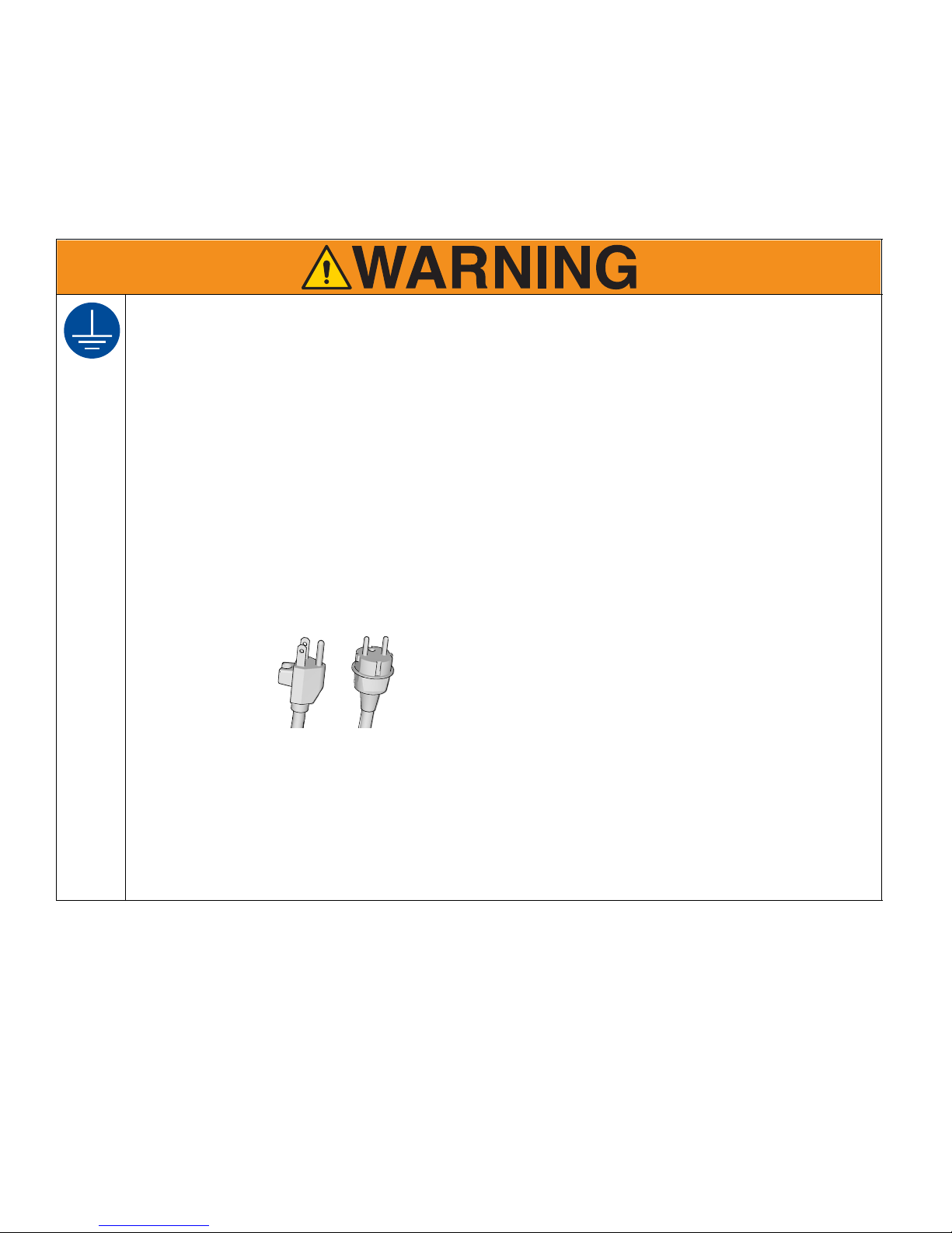
GROUNDING
This product must be grounded. In the event of an electrical short circuit, grounding reduces the risk of electric shock by providing an escape wire for the electric current. This product is equipped with a cord having a
grounding wire with an appropriate grounding plug. The plug must be plugged into an outlet that is properly
installed and grounded in accordance with all local codes and ordinances.
• Improper installation of the grounding plug is able to result in a risk of electric shock.
• When repair or replacement of the cord or plug is required, do not connect the grounding wire to either flat
blade terminal.
• The wire with insulation having an outer surface that is green with or without yellow stripes is the grounding
wire.
• Check with a qualified electrician or serviceman when the grounding instructions are not completely understood, or when in doubt as to whether the product is properly grounded.
• Do not modify the plug provided; if it does not fit the outlet, have the proper outlet installed by a qualified
electrician.
• This product is for use on a nominal 120V or 230V circuit and has a grounding plug similar to the plugs illustrated below.
ti24583a
• Only connect the product to an outlet having the same configuration as the plug.
• Do not use an adapter with this product.
Extension Cords:
• Use only a 3-wire extension cord that has a grounding plug and a grounding receptacle that accepts the
plug on the product.
• Make sure your extension cord is not damaged. If an extension cord is necessary use 12 AWG (2.5mm
minimum to carry the current that the product draws.
• An undersized cord results in a drop in line voltage and loss of power and overheating.
2
)
3A4603C Operation, Repair, Parts 3
Warnings
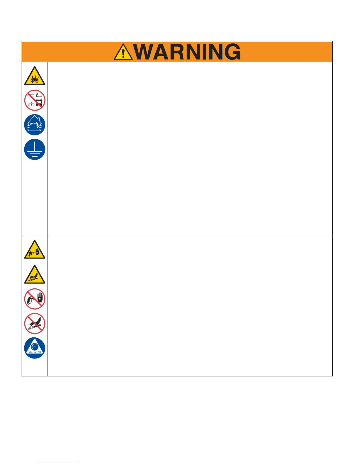
FIRE AND EXPLOSION HAZARD
Flammable fumes, such as solvent and paint fumes, in work area can ignite or explode. To help prevent fire
and explosion:
• Do not spray flammable or combustible materials near an open flame or sources of ignition such as cigarettes, motors, and electrical equipment.
• Paint or solvent flowing through the equipment is able to result in static electricity. Static electricity creates
a risk of fire or explosion in the presence of paint or solvent fumes. All parts of the spray system, including
the pump, hose assembly, spray gun, and objects in and around the spray area shall be properly grounded
to protect against static discharge and sparks. Use Graco conductive or grounded high-pressure airless
paint sprayer hoses.
• Verify that all containers and collection systems are grounded to prevent static discharge. Do not use pail
liners unless they are antistatic or conductive.
• Connect to a grounded outlet and use grounded extensions cords. Do not use a 3-to-2 adapter.
• Do not spray flammable or combustible liquids in a confined area.
• Sprayer generates sparks. Keep spray area well-ventilated. Keep a good supply of fresh air moving through
the area.
• Keep pump assembly in a well ventilated area when spraying, flushing, cleaning, or servicing. Do not spray
pump assembly.
• Do not smoke in the spray area or spray where sparks or flame is present.
• Do not operate light switches, engines, or similar spark producing products in the spray area.
• Keep area clean and free of paint or solvent containers, rags, and other flammable materials.
• Know the contents of the paints and solvents being sprayed. Read all Material Safety Data Sheets (MSDS)
and container labels provided with the paints and solvents. Follow the paint and solvents manufacturer’s
safety instructions.
• Fire extinguisher equipment shall be present and working.
SKIN INJECTION HAZARD
High-pressure spray is able to inject toxins into the body and cause serious bodily injury. In the event that
injection occurs, get immediate surgical treatment.
• Do not aim the gun at, or spray any person or animal.
• Keep hands and other body parts away from the discharge. For example, do not try to stop leaks with any
part of the body.
• Always use the nozzle tip guard. Do not spray without nozzle tip guard in place.
• Use Graco nozzle tips.
• Use caution when cleaning and changing nozzle tips. In the case where the nozzle tip clogs while spraying,
follow the Pressure Relief Procedure for turning off the unit and relieving the pressure before removing
the nozzle tip to clean.
• Equipment maintains pressure after power is shut off. Do not leave the equipment energized or under pressure while unattended. Follow the Pressure Relief Procedure when the equipment is unattended or not
in use, and before servicing, cleaning, or removing parts.
• Check hoses and parts for signs of damage. Replace any damaged hoses or parts.
• This system is capable of producing 3300 psi. Use Graco replacement parts or accessories that are rated
a minimum of 3300 psi.
• Always engage the trigger lock when not spraying. Verify the trigger lock is functioning properly.
• Verify that all connections are secure before operating the unit.
• Know how to stop the unit and bleed pressure quickly. Be thoroughly familiar with the controls.
4 3A4603C Operation, Repair, Parts
Warnings
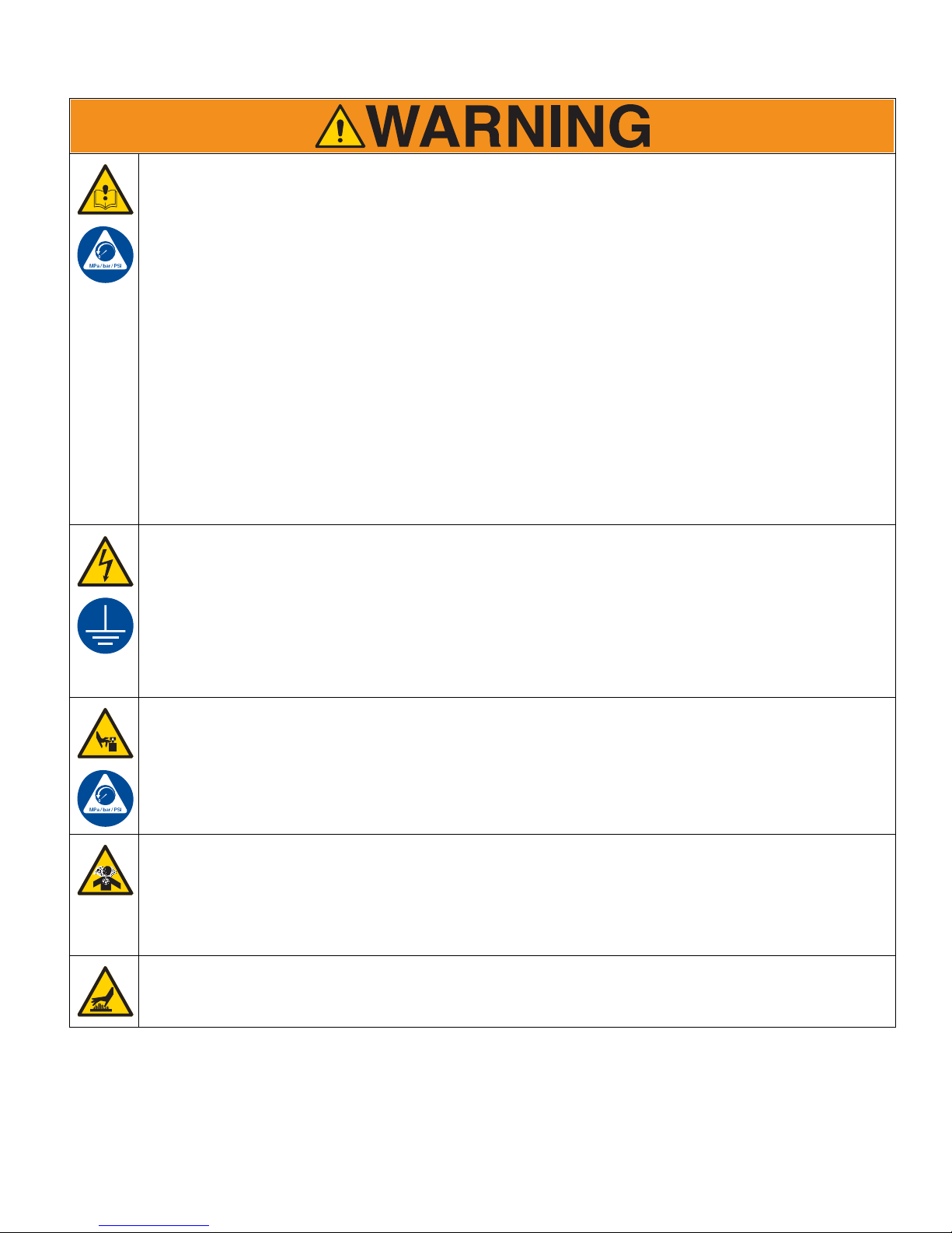
EQUIPMENT MISUSE HAZARD
Misuse can cause death or serious injury.
• Do not operate the unit when fatigued or under the influence of drugs or alcohol.
• Do not exceed the maximum working pressure or temperature rating of the lowest rated system component. See Technical Data in all equipment manuals.
• Use fluids and solvents that are compatible with equipment wetted parts. See Technical Data in all equipment manuals. Read fluid and solvent manufacturer’s warnings. For complete information about your material, request Safety Data Sheet (SDS) from distributor or retailer.
• Do not leave the work area while equipment is energized or under pressure.
• Turn off all equipment and follow the Pressure Relief Procedure when equipment is not in use.
• Check equipment daily. Repair or replace worn or damaged parts immediately with genuine manufacturer’s
replacement parts only.
• Do not alter or modify equipment. Alterations or modifications may void agency approvals and create safety
hazards.
• Make sure all equipment is rated and approved for the environment in which you are using it.
• Use equipment only for its intended purpose. Call your distributor for information.
• Route hoses and cables away from traffic areas, sharp edges, moving parts, and hot surfaces.
• Do not kink or over bend hoses or use hoses to pull equipment.
• Keep children and animals away from work area.
• Comply with all applicable safety regulations.
ELECTRIC SHOCK HAZARD
This equipment must be grounded. Improper grounding, setup, or usage of the system can cause electric
shock.
• Turn off, disconnect power cord, and disconnect battery before servicing equipment.
• Connect only to grounded electrical outlets.
• Use only 3-wire extension cords.
• Ensure ground prongs are intact on power and extension cords.
• Do not expose to rain. Store indoors.
• Wait thirty minutes after disconnecting power cord before servicing.
MOVING PARTS HAZARD
Moving parts can pinch, cut or amputate fingers and other body parts.
• Keep clear of moving parts.
• Do not operate equipment with protective guards or covers removed.
• Pressurized equipment can start without warning. Before checking, moving, or servicing equipment, follow
the Pressure Relief Procedure and disconnect all power sources.
TOXIC FLUID OR FUMES HAZARD
Toxic fluids or fumes can cause serious injury or death if splashed in the eyes or on skin, inhaled, or swallowed.
• Read Safety Data Sheet (SDS) to know the specific hazards of the fluids you are using.
• Store hazardous fluid in approved containers, and dispose of it according to applicable guidelines.
BURN HAZARD
Equipment surfaces and fluid that’s heated can become very hot during operation. To avoid severe burns:
• Do not touch hot fluid or equipment.
3A4603C Operation, Repair, Parts 5
Warnings
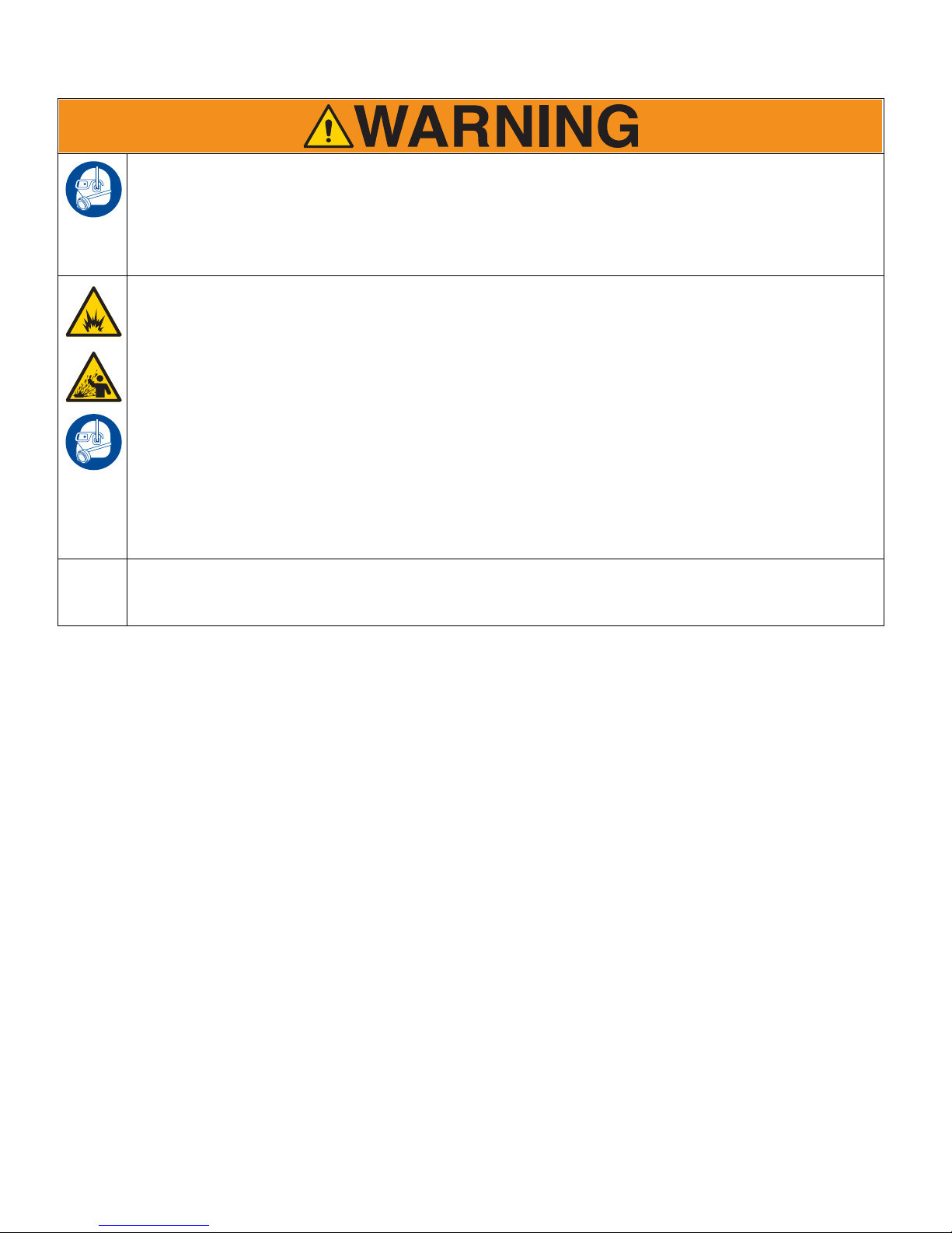
PERSONAL PROTECTIVE EQUIPMENT
Wear appropriate protective equipment when in the work area to help prevent serious injury, including eye
injury, hearing loss, inhalation of toxic fumes, and burns. This protective equipment includes but is not limited
to:
• Protective eyewear, and hearing protection.
• Respirators, protective clothing, and gloves as recommended by the fluid and solvent manufacturer.
BATTERY HAZARD
The battery may leak, explode, cause burns, or cause an explosion if mishandled. Contents of an open battery can cause severe irritation and/or chemical burns. If on skin, wash with soap and water. If in eyes, flush
with water for at least 15 minutes and get immediate medical attention.
• Only use the battery type specified for use with the equipment. See Technical Data.
• Connecting cables to the battery creates sparks. Replace battery only in well-ventilated area and away
from flammable or combustible materials, including paints and solvents.
• Remove watches, rings or other metal objects before servicing.
• Only use tools with insulated handles. Do not lay tools or metal parts on top of battery.
• Do not dispose of battery in fire or heat above 50°C (122°F). The battery is capable of exploding.
• Do not throw into fire.
• Do not expose battery to water or rain.
• Do not disassemble, crush, or penetrate the battery.
• Do not use or charge a battery that is cracked or damaged.
• Follow local ordinances and/or regulations for disposal.
CALIFORNIA PROPOSITION 65
This product contains a chemical known to the State of California to cause cancer, birth defects or other
reproductive harm. Wash hands after handling.
6 3A4603C Operation, Repair, Parts

Tip Selection
ti27606a
in.
(cm)
ti27505a
in.
(cm)
ti27506a
in.
(cm)
ti27507a
in.
ti27510a
ti27605a
Tip Selection
(cm)
LL5213* 2 (5)
LL5215* 2 (5)
LL5217
LL5219
LL5315
LL5317
LL5319
LL5321
LL5323
LL5325
LL5327
LL5329
LL5331
LL5333
LL5335
LL5355
4 (10)
4 (10)
4 (10)
4 (10)
4 (10)
4 (10)
4 (10)
4 (10)
4 (10)
4 (10)
4 (10)
4 (10)
4 (10)
4 (10)
LL5417 6 (15)
LL5419 6 (15)
LL5421 6 (15)
LL5423 6 (15)
LL5425 6 (15)
LL5427 6 (15)
LL5429 6 (15)
LL5431 6 (15)
LL5435 6 (15)
LL5621 12 (30)
LL5623 12 (30)
LL5625 12 (30)
LL5627 12 (30)
LL5629 12 (30)
LL5631 12 (30)
LL5635 12 (30)
LL5639 12 (30)
ti27508a
ti27509a
*Use 100 mesh filter to reduce tip clogs.
3A4603C Operation, Repair, Parts 7
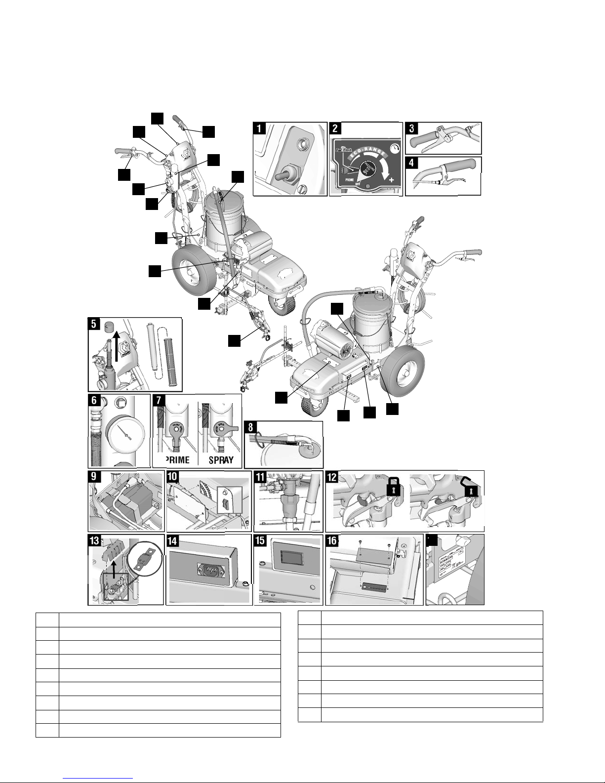
Component Identification (ES 1000)
ti30321a
PRIME SPRAY
16
1
1
2
3
4
6
7
5
8
9
2
3
6
7
8
9
11
10
14
17
15
16
12
13
4
5
11
10
12
14
15
13
17
Component Identification (ES 1000)
1 ON/OFF switch
2 Pressure control
3 Spray gun trigger
4 Turn control
5 Filter
6 Gauge
7 Prime/Pressure valves
8 Drain and siphon hoses
9 Battery compartment
10 Inverter circuit breakers
11 Pump
12 Trigger safety
13 Fuse
14 Charging port
15 Voltage meter
16 LED status center
17 Serial ID
8 3A4603C Operation, Repair, Parts
Battery and Charger
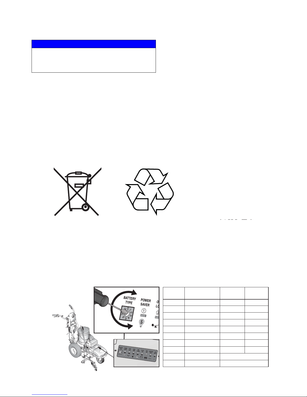
BATTERY TYPE SELECTOR SETTINGS
Switch
Position Description Boost/Vdc Float/Vdc
0 Charger Off
1 Gel USA 14.0 13.7
2 AGM 1 14.1 13.4
3 AGM 2 14.6 13.7
4 Sealed Lead Acid 14.4 13.6
5 Gel Euro 14.4 13.8
6 Open Lead Acid 14.8 13.3
7 Calcium 15.1 13.6
8 De-sulphation 15.5
(4 hours then Off)
9 Not used
ti30488a
Battery and Charger
NOTICE
If the battery level is below 9.7V, the on-board charger
will not be allowed to charge the battery. Charge battery
with an external charger to raise the level above 10.0V to
activate the on-board charger, or replace the battery.
• The LineLazer ES 1000 is designed to work with
one or two 12V 100 Ahr DEEP CYCLE Absorbent
Glass Mat (AGM) batteries. Maximum battery size is
13” x 9” x 7” (33cm x 23cm x 18cm).
• Battery Protection Features: Unit is designed to
protect the battery by shutting down at 10.5V and
not allowing charging to occur above 15.5V.
• Battery Operating Temperature: -4-140°F
(-20-60°C)
• Battery Charging Temperature: 14-140°F
(-10-60°C)
• Battery Storage Temperature: -4-140°F
(-20-60°C)
• Self Discharge: Lead acid batteries can self-discharge in as little as 3 months depending on storage
temperatures. The hotter the storage temperature,
the faster the self-discharge occurs. To prevent
damage to the battery, it is important to keep the
battery in a charged state.
• Battery Life: Battery recharge cycles depend on
the depth of discharge per cycle. A battery that is
discharged to 50% depth will get over twice as
many cycles in its life compared to it being discharged to 100% depth each cycle.
Battery Disposal
Do not place batteries in the trash. Recycle batteries according to local regulations.
Battery Type and Charging Profiles
Graco recommends using a 12V 100 Ahr Absorbent
Glass Mat (AGM) DEEP CYCLE battery.The charger is
set for this charging profile from the factory. If a different
battery is used, the charging profile can be set at the
LED Status Center. The initial charge rate is 30 amps.
Only use batteries that allow an initial charge rate of 30
amps or higher.
3A4603C Operation, Repair, Parts 9
Use a small flat head screw driver to turn the arrow to
point at the number that correlates with the chosen
battery.
Battery and Charger
ti30322a
ti30359a
ti30360a
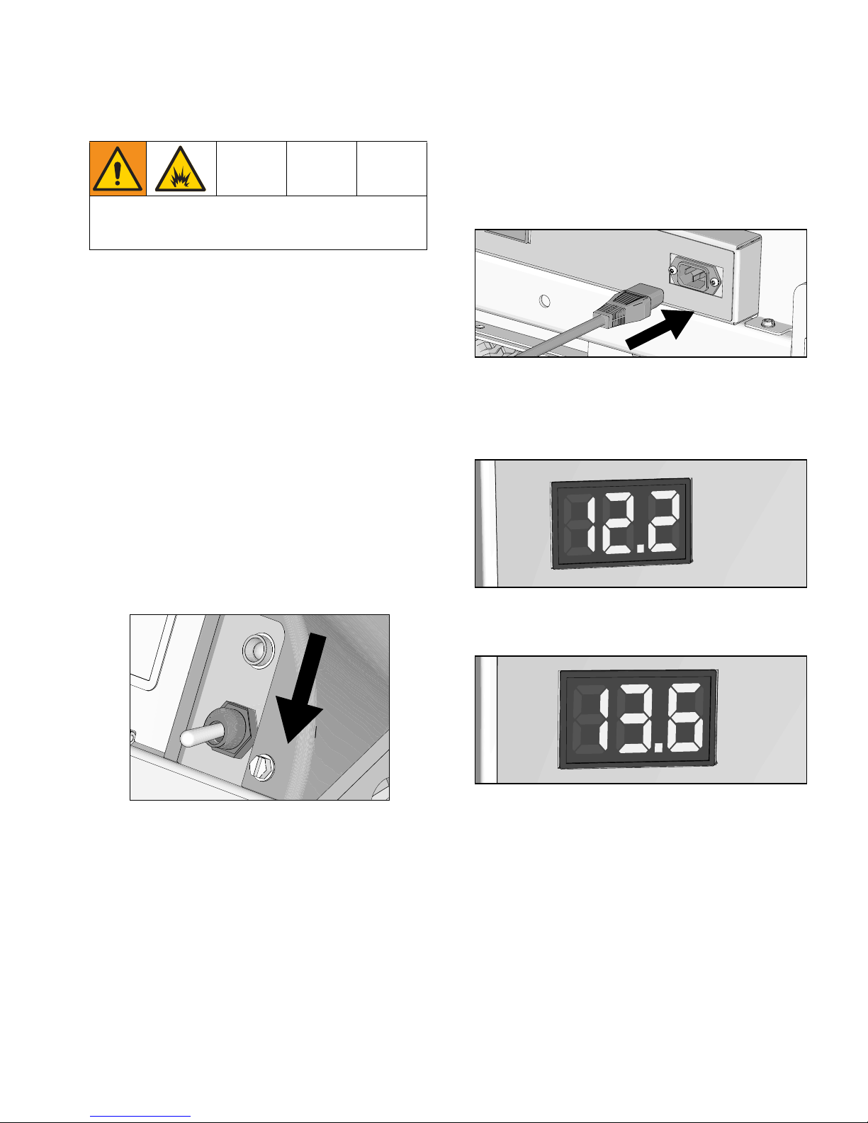
Charging the Battery
Replace and charge battery only in well-ventilated
area and away from flammable or combustible materials, including paints and solvents.
If the battery level is below 9.7V, the on-board charger
will not be allowed to charge the battery. Charge battery
with an external charger to raise the level above 10.0V to
activate the on-board charger, or replace the battery.
3. Plug charging cord into charging port on the unit.
Connect an extension cord, minimum 12AWG
(2.5mm
2
), to the charging cord and plug it into wall
power.
Use an extension cord with an undamaged ground contact. If an extension cord is necessary, use a 3-wire, 12
AWG (2.5 mm
2
) minimum.
Batteries are fully charged when leaving the factory.
Due to self-discharging of the battery, charge battery
before first use. It takes ~3 hours to charge a dead battery to 80%. It takes ~5 hours to charge a fully depleted
battery (double these times for 2 battery unit).
1. Place unit in dry, well-ventilated area and away from
flammable or combustible materials, including
paints and solvents.
2. Ensure power switch is in OFF position.
ti30358a
4. When power is connected the voltmeter will turn on
and the charger will immediately begin charging.
User should be able to see voltmeter start to climb
to indicate charging is occurring.
5. Battery will charge to 14.6-14.8 volts and then it will
come back down to ~13.6 volts when fully charged.
10 3A4603C Operation, Repair, Parts
Grounding Procedure (AC Wall Power)
ti24584a
Grounding Procedure
(AC Wall Power)
This equipment must be grounded to reduce the risk
of static sparking and electric shock. An electric
shock or static spark can cause fumes to ignite or
explode. An improper ground can cause electric
shock. A good ground provides an escape wire for
the electric current.
Position the striper so the wheels are on a true
grounded surface. Not on pavement.
The plug must be plugged into an outlet that is properly
installed and grounded in accordance with all local
codes and ordinances.
Do not modify the plug provided; if it does not fit the
outlet, have the proper outlet installed by a qualified
electrician.
Do not place pail on a non-conductive surface such as
paper or cardboard which interrupts grounding
continuity.
Always ground a metal pail: connect a ground wire to
the pail. Clamp one end to the pail and the other end to
a true earth ground such as a water pipe.
Power Requirements
• 100-120V units require 100-120 VAC, 50/60 Hz, 12
or 15A, 1 phase.
• 230V units require 230 VAC, 50/60 Hz, 7 or 9A, 1
phase.
Extension Cords
Use an extension cord with an undamaged ground contact. If an extension cord is necessary, use a 3-wire, 12
AWG (2.5 mm
2
) minimum.
Pails
Solvent and oil-based fluids: follow local code. Use
only conductive metal pails, placed on a grounded surface such as concrete.
To maintain ground continuity when sprayer is
flushed or pressure is relieved: hold metal part of
spray gun firmly to the side of a grounded metal pail
then trigger gun.
ti24585a
3A4603C Operation, Repair, Parts 11
Grounding Procedure (Battery Power)
ti24584a
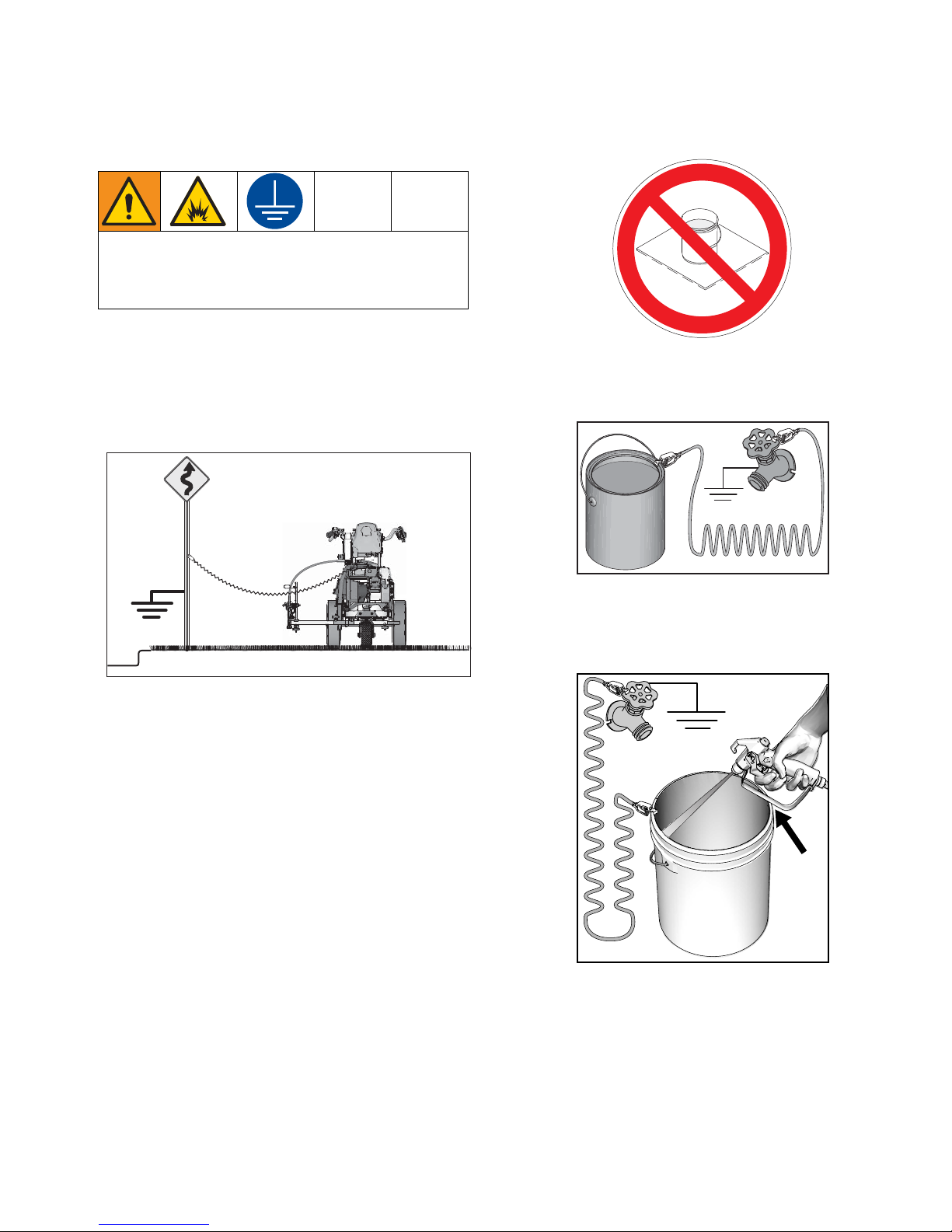
Grounding Procedure
(Battery Power)
This equipment must be grounded to reduce the risk
of static sparking. Static sparking can cause fumes to
ignite or explode. Grounding provides an escape wire
for the electric current.
1. Position striper so that the tires are not on pavement.
2. Striper is shipped with a grounding clamp.
Grounding clamp must attach to grounded object
(e.g., metal sign post).
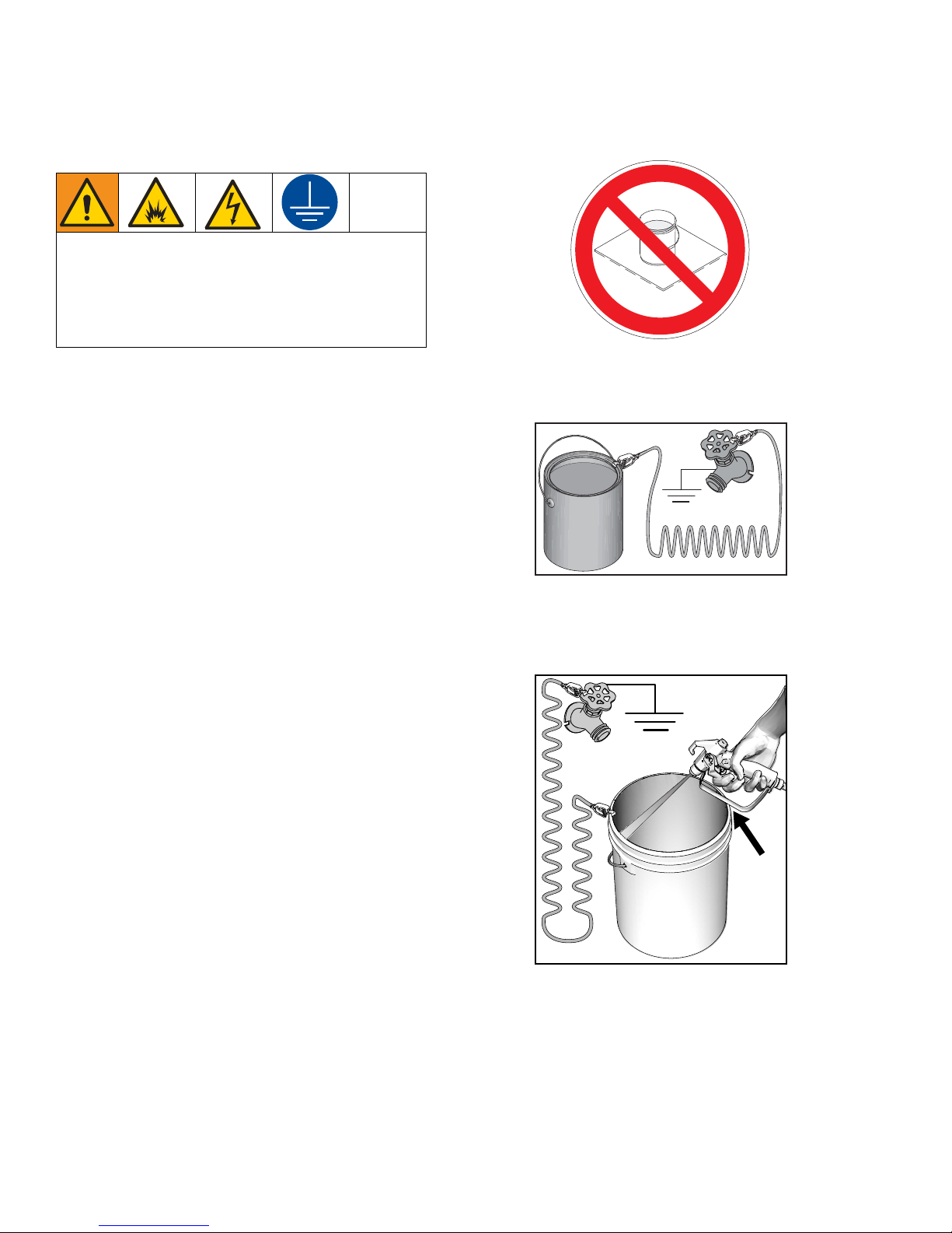
Do not place pail on a non-conductive surface such as
paper or cardboard which interrupts grounding
continuity.
Always ground a metal pail: connect a ground wire to
the pail. Clamp one end to the pail and the other end to
a true earth ground such as a water pipe.
ti27615a
Pails
Solvent and oil-based fluids: follow local code. Use
only conductive metal pails, placed on a grounded surface such as concrete.
To maintain ground continuity when sprayer is
flushed or pressure is relieved: hold metal part of
spray gun firmly to the side of a grounded metal pail
then trigger gun.
ti24585a
12 3A4603C Operation, Repair, Parts
Pressure Relief Procedure
ti30322a
ti30323a
ti27608a
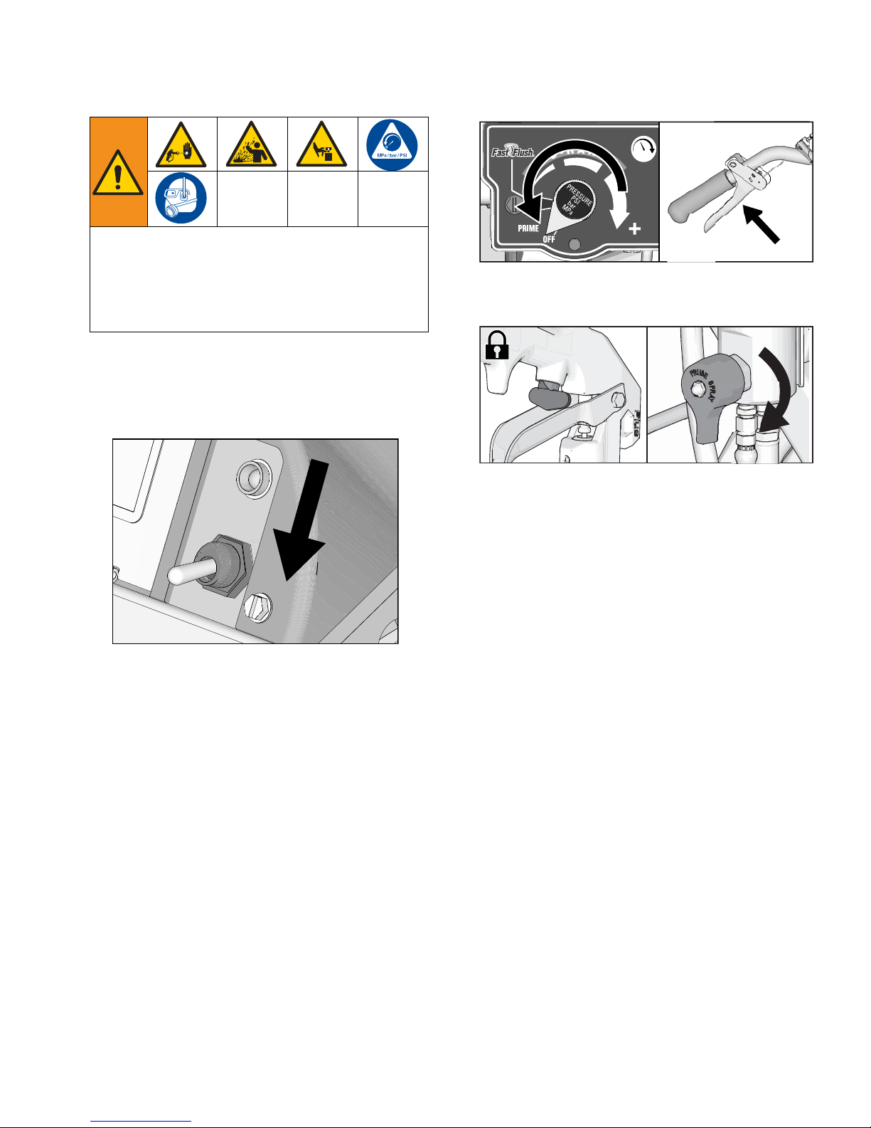
Pressure Relief Procedure
This equipment stays pressurized until pressure is
manually relieved. To help prevent serious injury from
pressurized fluid, such as skin injection, splashing
fluid and moving parts, follow the
Procedure
when you stop dispensing and before
cleaning, checking, or servicing the equipment.
1. Perform Grounding Procedure if using flammable
materials.
2. Turn ON/OFF Switch to OFF.
Pressure Relief
3. Turn pressure control to lowest setting. Trigger all
guns to relieve pressure.
4. Engage all gun trigger locks. Turn prime valve
down.
v
5. If you suspect the spray tip or hose is clogged or
that pressure has not been fully relieved:
a. VERY SLOWLY loosen the tip guard retaining
nut or the hose end coupling to relieve pressure
gradually.
b. Loosen the nut or coupling completely.
c. Clear the obstruction in the hose or tip.
3A4603C Operation, Repair, Parts 13
Setup/Startup
ti24639a
ti30322a
ti27612a
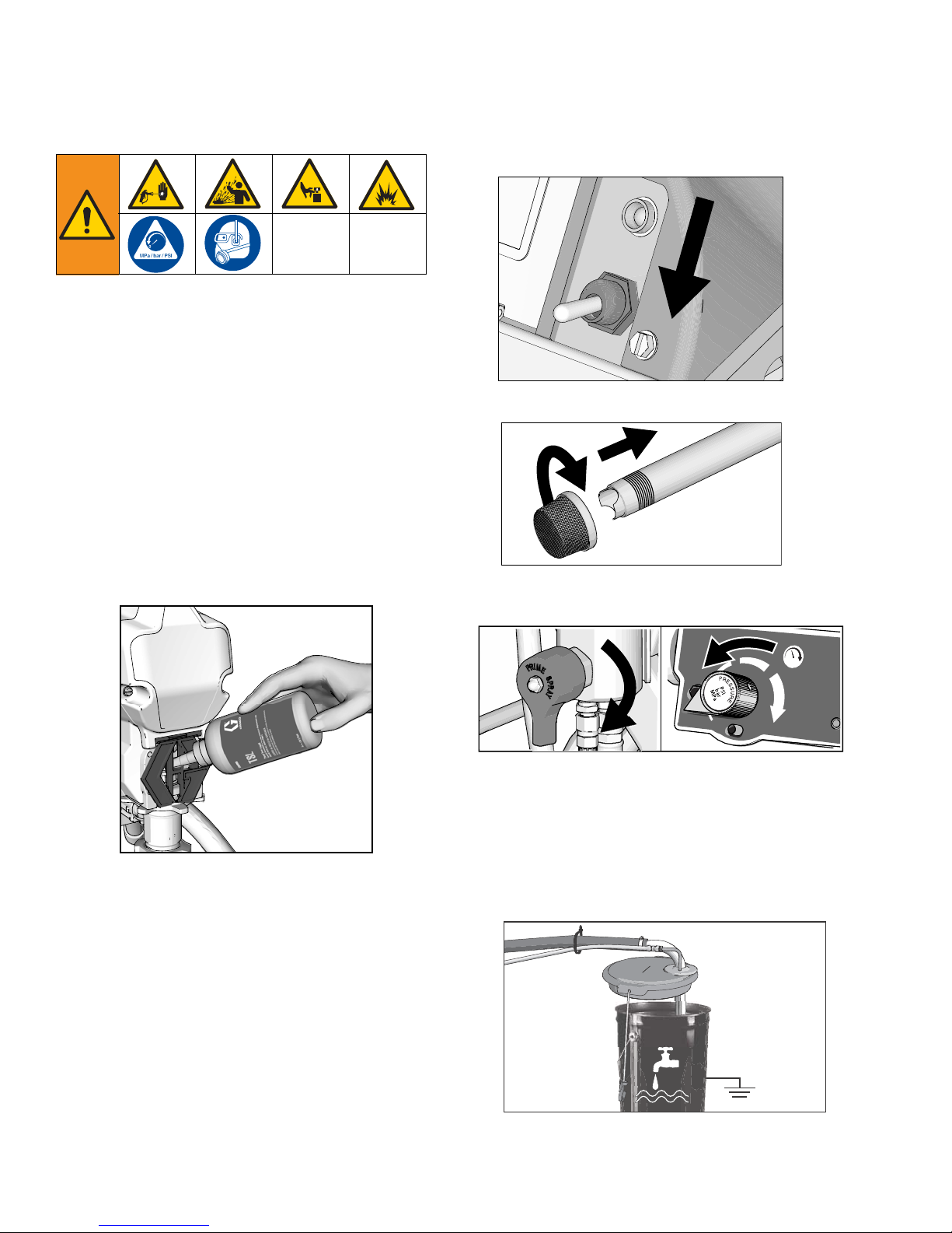
Setup/Startup
5. Turn On/OFF Switch to OFF.
1. Perform
Pressure Relief Procedure
, page 13
.
2. Charge Battery, page 10.
3. Perform Grounding Procedure (AC Wall Power),
page 11, or Grounding Procedure (Battery
Power), page 12, if using flammable materials.
4. Fill throat packing nut with TSL to prevent
premature packing wear. Do this daily or each time
you spray.
a. Place the TSL bottle nozzle into the top center
opening in the grill at the front of the sprayer.
b. Squeeze bottle to dispense enough TSL to fill
the space between the pump rod and packing
nut seal.
6. If removed, install strainer.
7. Turn prime valve down. Turn pressure control counterclockwise to lowest pressure.
ti27614a
NOTE: If running off wall power, plug cord into charging
port. If using an extension cord, use a 3-wire, 12 AWG
(2.5mm
14 3A4603C Operation, Repair, Parts
2
) minimum with an undamaged ground contact.
NOTE: Minimum hose size for proper sprayer operation is 1/4 in. x 50 ft for LL ES 1000.
8. Place siphon tube set in grounded metal pail partially filled with flushing fluid. Attach ground wire to
true earth ground. Use water to flush water-based
paint and mineral spirits to flush oil-based paint and
storage oil.
ti27613a
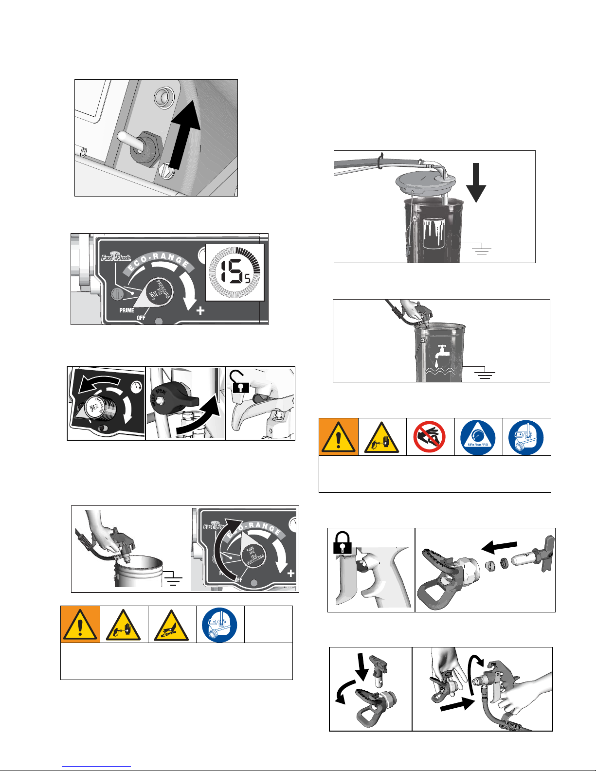
Setup/Startup
ti30324a
ti30325a
ti27771a
ti30349a
ti27775a
ti27776a
9. Turn ON/OFF Switch to ON:
10. Turn pressure control to prime. Allow fluid to circulate for 15 seconds.
11. Turn pressure down, turn prime valve horizontal.
Disengage gun trigger lock.
13. Inspect fittings for leaks. If leaks occur, turn sprayer
OFF immediately. Perform
dure
, page 13. Tighten leaky fittings. Repeat
Setup/Startup
, steps 1 - 17. If no leaks, continue to
Pressure Relief Proce-
trigger gun until system is thoroughly flushed. Proceed to step 18.
14. Place siphon tube in paint pails.
ti27613a
15. Trigger all guns again into a flushing fluid pail until
paint appears. Assemble tips and guards.
12. Hold all guns against a grounded metal flushing pail.
Trigger guns and increase fluid pressure slowly until
pump runs smoothly. Turn up as needed to
prime/spray.
High-pressure spray is able to inject toxins into the
body and cause serious bodily injury. Do not stop
leaks with hand or rag.
ti27774a
SwitchTip and Guard Assembly
To avoid serious injury from skin injection do not put
your hand in front of the spray tip when installing or
removing the spray tip and tip guard.
1. Engage trigger lock. Use end of SwitchTip to press
OneSeal into tip guard, with curve matching tip bore.
2. Insert SwitchTip in tip bore and firmly thread assembly onto gun.
3A4603C Operation, Repair, Parts 15
Gun Placement
ti27777a
ti27778a
ti28129a
ti28130a
1
2
ti27781a
ti27782a
ti27782a
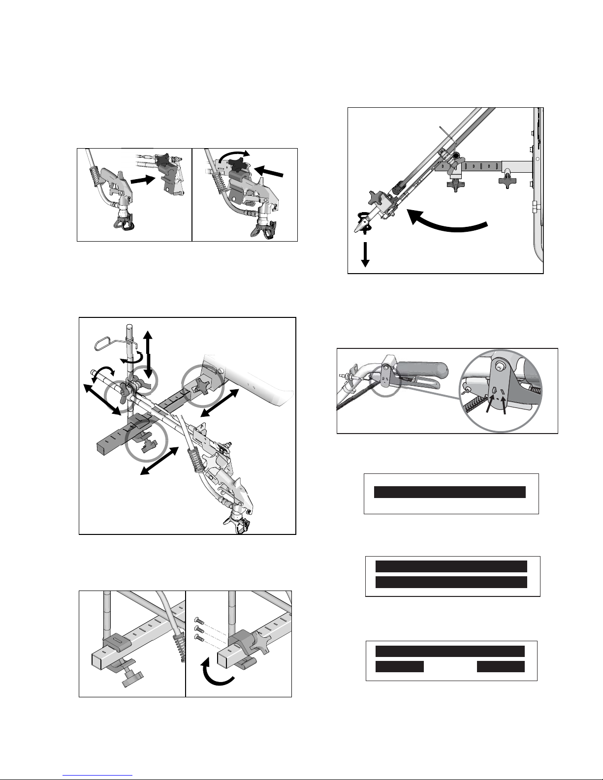
Gun Placement
Install Gun
1. Insert guns into gun holder. Tighten clamps.
Position Gun
2. Position gun: up/down, forward/reverse, left/right.
See Gun Positions Chart, page 17 for examples.
Another option can be to swing the gun out at an angle
and rotate the tip guard. This results in better visibility
for the user.
Select Guns
3. Connect gun cables to left or right gun selector
plates.
NOTE: When striping above a curb, the mounting clamp
can be rotated for clearance.
ti27780a
a. One gun: Disconnect one gun selector plate
from trigger.
b. Both guns simultaneously: Adjust both gun
selector plates to the same position.
c. Solid-skip and skip-solid: Adjust solid-line gun
to position 1 and skip-line to position 2.
16 3A4603C Operation, Repair, Parts
Gun Positions Chart
1
2
3
4
5
6
7
ti27786a
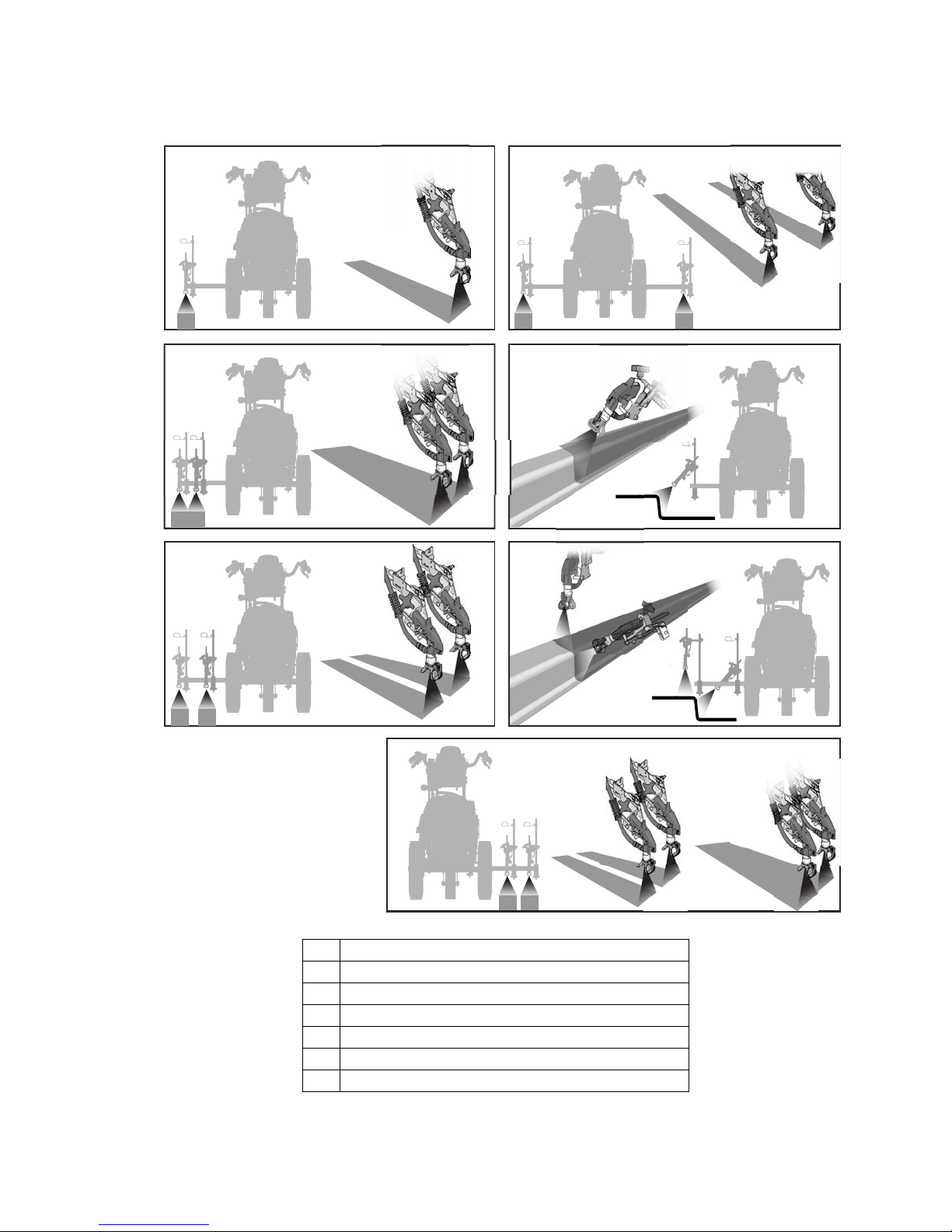
Gun Placement
1 One line
2 One line up to 24 in. (61cm) wide
3 Two lines
4 One line or two lines to spray around obstacles
5 One gun curb
6 Two gun curb
3A4603C Operation, Repair, Parts 17
7 Two lines or one line up to 24 in. (61 cm) wide
Gun Placement
ti30326a
ti27796c
ti30327a
ti27797a
ti30328a
ti30329a
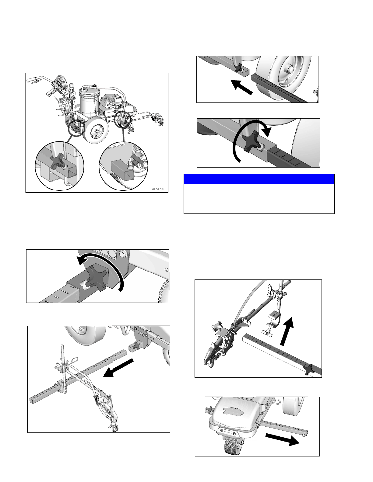
Gun Arm Mounts
This unit is equipped with front and rear gun arm
mounts.
Change Gun Position
3. Slide gun arm assembly into desired gun arm
mounting slot.
4. Tighten gun arm knob into gun arm mounting slot.
ti27798a
NOTICE
Make sure all hoses, cables, and wires are properly
routed through brackets and do NOT rub on tire.
Contact with tire will result in damaged hoses, cables,
and wires.
(Front and Back)
1. Loosen gun arm knob and remove from gun arm
mounting slot.
2. Slide gun arm assembly (including gun and hoses)
out from gun arm mounting slot.
Change Gun Position
(Left and Right)
Removal
1. Loosen vertical gun arm knob on gun arm mounting
bar and remove.
2. Extend mounting bar on opposite side of the
machine.
18 3A4603C Operation, Repair, Parts
 Loading...