

Page 1
INSTRUCTIONS-PARTS LIST
308943
This manual contains important
warnings and information.
READ AND KEEP FOR REFERENCE.
INSTRUCTIONS
Kit, Swivel Wheel
Line Lazer 3500, 5000
Model 241105, Series A
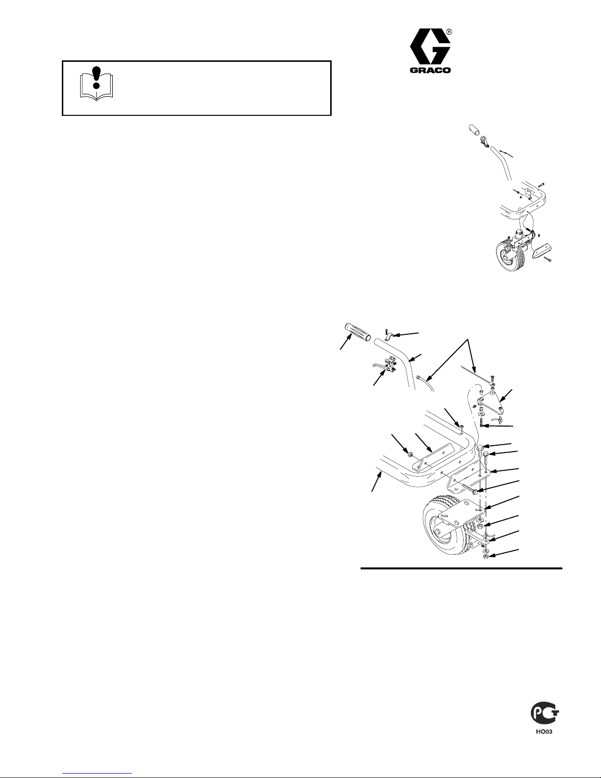
Old Caster Wheel Removal
Fig. 1. Remove old caster wheel and associated wheel
hardware as outlined in the steps following.
20
21
19
Rev. D
3
1 . Unfasten release lever bracket (21) and remove
release lever (22) from handle (19).
2 . Remove cable (3), actuator lever (94) and lever
hardware by unfastening capscrew (37) and locknut (26).
3 . Remove old swivel caster (114), caster latch (112)
and related hardware by unfastening capscrews
(87,117), and nuts (40,115).
4 . Unfasten two locknuts (40) from capscrews (39)
and remove rear caster bracket (31) and front
caster bracket (38) from cart (110).
5 . Remove handle grip (20) from handle (19).
Fig. 1
22
110
40
31
94
26
37
117
87
38
39
114
115
112
40
8885A
GRACO INC. P.O. BOX 1441 MINNEAPOLIS, MN 55440–1441
ECOPYRIGHT 1999, GRACO INC.
Graco Inc. is registered to I.S. EN ISO 9001
Page 2
Installation
Assemble the swivel wheel kit according to the following steps.
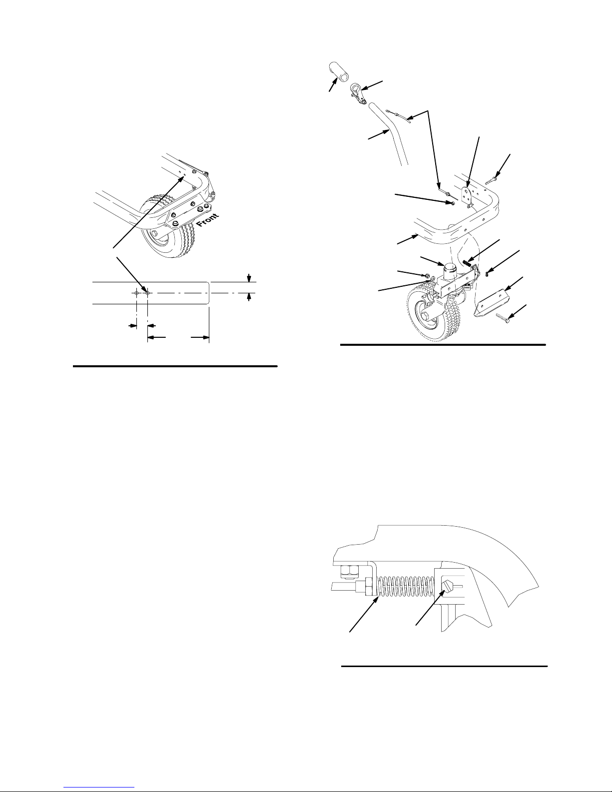
1 . Put front of cart on cement block or other type of
support in place of removed caster wheel.
10 . Fig. 4. Install wire stop (7) on cable wire (10) and
finger tighten wire stop screw.
9
18
10
2 . Fig. 2. Drill two holes thru right side of chassis
frame as viewed from front.
1.0 in
4X Ĭ .330
Thru. Both Walls
1.0 in
5.55 in
Fig. 2
3 . Fig. 3. Mount cable bracket (11) on right side of
cart (110), as viewed from front, with two flange
screws (15) and two lock nuts (16).
4 . Slide actuator lever (9) on cart handle (H) and
tighten. Install handle grip (18). Replace other
handle grip if needed.
5 . Insert two cap screws (13) into front caster
bracket (12) and mount on front of cart (110).
6 . Assemble swivel caster (1) to cart (110) and cap
screws (13) extending thru cart. Fasten with two
lock nuts (14) and washers (19) and tighten.
Front
8851A
11
Fig. 3
H
16
110 Ref
19
1
14
15
8
7
12
13
Cable Adjustment
Adjust the cable as follows:
1 . Fig. 4. Make sure cable is routed between the top
of sprayer frame and underneath the motor mount
plate.
2 . Check that cable is snug and cable nut (A) under
spring is tight. Extend cable wire and draw tight in
wire stop (7). Tighten wire stop screw.
3 . Check that release lever frees wheel to turn.
Readjust cable if necessary.
7 . Install one end of cable (10) in actuator lever (9).
8 . Route cable (10) from actuator lever (9) down
handle and between cart base (110) and motor
mount plate (108) to swivel caster (1). Fasten
cable to cable bracket using nut provided with
cable.
9 . Install compression spring (8) over cable wire and
in front of caster wheel (1).
2 308943
Fig. 4
A
7
8835A
Page 3

Caster Wheel Alignment
Operation
(See letter call–outs in Parts drawing on page 5.)
1 . Loosen bolt (D).
2 . Push line striper forward following a straight refer–
ence line.
3 . Stop.
4 . Tighten bolt (D).
Continuous Radius Striping
1 . Push line striper around radius.
2 . Stop.
3 . Tighten knob (E).
4 . Verify accuracy, then paint.
Swivel Hub Bearing (G) Adjustment
1 . To swivel less freely, tighten nut (A). 2 . To swivel more freely, loosen nut (A).
Operation
Caster Wheel
(See letter call–outs in Parts drawing on page 5.)
1 . Once each year, tighten nut (A) until spring washer
bottoms out. Then back off the nut 1/2 to 3/4 turn.
2 . Once each year, tighten nut (B) until it begins to
compress spring washer. Then tighten the nut an
additional 1/4 turn.
3 . Once each month, grease the wheel bearing (F).
4 . Check pin (C) for wear. If pin is worn out, therewill
be play in the caster wheel. Reverse or re–place
the pin as needed.
308943 3
Page 4

Parts Drawing/List
t
18
9
10
Ref
No. Part No. Description Qty
241105 KIT ASSY, swivel wheel Ref
1 287881 . CASTER, swivel 1
1a 240719 . CASTER ASSY, swivel 1
1aa 240940 . . BRACKET, hub 1
1ab 240942 . . SHAFT, fork 1
1ac 193528 . . ARM, detent 1
1ad 193662 . . PIN, locking, tapered 1
1ae 110754 . . SCREW, cap, soc hd 2
1af 181818 . . KNOB, pronged 1
1ag 114548 . . BEARING, bronze 2
1ah 113484 . . SEAL, grease 1
1aj 113485 . . BEARING, cup/cone 2
1ak 112825 . . SPRING, belleville 1
1am 112405 . . NUT, lock 1
1an 114648 . . CAP, dust 1
1ap 15J603 . . WASHER, plain 1
1ar 113962 . . WASHER, hardened 1
1as 114681 . . SCREW, cap, hex hd 1
1at 193660 . . DISK, adjuster 1
1au 193661 . . JAW 1
1av 108483 . . SCREW, shoulder, soc hd 1
1aw 120476 . . BOLT 1
2 113471 . SCREW, cap, hex hd 1
3 112405 . NUT, lock 1
4 112825 . SPRING, belleville 1
5 193658 . SPACER, seal 2
6 114549 . WHEEL, pneumatic 1
7 114802 . STOP, wire 1
8 114682 . SPRING, compression 1
9 194310 . LEVER, actuator 1
10 241445 . CABLE 1
11 15F910 . BRACKET, cable 1
12 240991 . BRACKET, caster, front 1
13 114982 . SCREW, cap, flang hd 2
14 101566 . NUT, lock 2
15 110837 . SCREW, flange, hex 2
16 111040 . NUT, lock, nylock 2
18 108063 . GRIP, handle 2
19 100731 . WASHER 2
11
15
16
1aa (Shee
8
1
7
14
12
19
2
13
5
4
6
ti8386a
Sheet 1 of 2
4 308943
Page 5

Parts Drawing/List
1ac 1aa 1af1ad 1ae
A
C
A
1ab
FB
Detail A
1ag
1ab (Ref)1an1am
1ak
1aj1ah
1aw1ap 1ar 1as 1at 1au 1av
A–A
Sheet 2 of 2
A
G
D3 (Ref)
1aa(Ref)
1af (Ref)
E
8838B
308943 5
Page 6

Graco Phone Number
TO PLACE AN ORDER, contact your Graco distributor, or call this number to identify the distributor closest to you:
1–800–690–2894 Toll Free.
All written and visual data contained in this document reflects the latest product information available at the time of publication.
Graco reserves the right to make changes at any time without notice.
International Offices: Belgium, Korea, China, Japan
GRACO INC. P.O. BOX 1441 MINNEAPOLIS, MN 55440–1441
6 308943
Graco Headquarters: Minneapolis
http://www.graco.com
2/1999, Rev 9/2006
 Loading...