

Graco LineLazer 3400 Operation - Repair - Parts
Operation, Repair, Parts
ti30298a
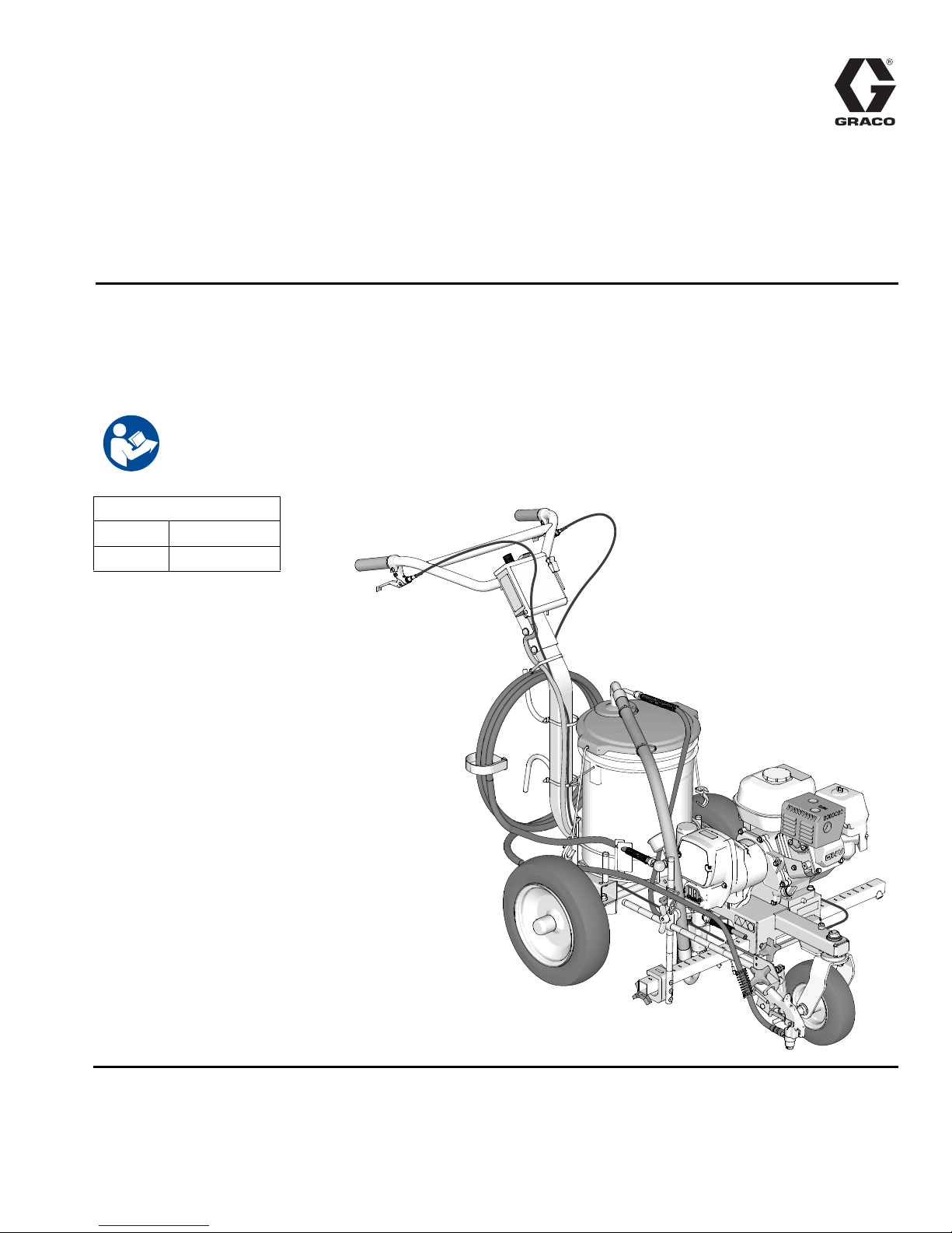
LineLazer™ 3400 Airless Line Striper
3A4587B
For the application of line striping materials. For professional use only. For outdoor use
only. Not approved for use in explosive atmospheres or hazardous locations.
Model: 25M224
3300 psi (22.8 MPa, 228 bar) Maximum Operating Pressure
Important Safety Instructions
Read all warnings and instructions in this manual, related manuals, and on the
equipment. Be familiar with the controls and the proper usage of the equipment.
Save these instructions.
Related Manuals:
311254 Gun
309250 Pump
EN

Contents
Tip Selection . . . . . . . . . . . . . . . . . . . . . . . . . . . . . . 6
Component Identification . . . . . . . . . . . . . . . . . . . . 7
Grounding Procedure (For Flammable Materials
Only) . . . . . . . . . . . . . . . . . . . . . . . . . . . . . . . . . . 8
Pails . . . . . . . . . . . . . . . . . . . . . . . . . . . . . . . . . . 8
Pressure Relief Procedure . . . . . . . . . . . . . . . . . . . 9
Front Wheel Alignment: . . . . . . . . . . . . . . . . . . 10
Operation . . . . . . . . . . . . . . . . . . . . . . . . . . . . . . . . 11
Setup . . . . . . . . . . . . . . . . . . . . . . . . . . . . . . . . . 11
Startup . . . . . . . . . . . . . . . . . . . . . . . . . . . . . . . 12
Rac Tip and Guard Assembly . . . . . . . . . . . . . 14
Gun Placement . . . . . . . . . . . . . . . . . . . . . . . . . . . 15
Install Gun . . . . . . . . . . . . . . . . . . . . . . . . . . . . . 15
Position Gun . . . . . . . . . . . . . . . . . . . . . . . . . . . 15
Paint Stripe Width . . . . . . . . . . . . . . . . . . . . . . . . . 17
Spray Test Stripe . . . . . . . . . . . . . . . . . . . . . . . 17
Clearing Tip Clogs . . . . . . . . . . . . . . . . . . . . . . 17
Clean-up . . . . . . . . . . . . . . . . . . . . . . . . . . . . . . . . . 18
Flushing Recommendations . . . . . . . . . . . . . . . . 21
Troubleshooting . . . . . . . . . . . . . . . . . . . . . . . . . . 22
Displacement Pump . . . . . . . . . . . . . . . . . . . . . . . 24
Removal . . . . . . . . . . . . . . . . . . . . . . . . . . . . . . 24
Repair . . . . . . . . . . . . . . . . . . . . . . . . . . . . . . . . 24
Installation . . . . . . . . . . . . . . . . . . . . . . . . . . . . . 25
Drive Housing and Connecting Rod . . . . . . . . . . 26
Removal . . . . . . . . . . . . . . . . . . . . . . . . . . . . . . 26
Installation . . . . . . . . . . . . . . . . . . . . . . . . . . . . . 26
Pinion Assembly/Clutch Armature/Clamp . . . . . 27
Pinion Assembly/Clutch Armature Removal . . . 27
Installation . . . . . . . . . . . . . . . . . . . . . . . . . . . . . 28
Clamp Removal . . . . . . . . . . . . . . . . . . . . . . . . 29
Clamp Installation . . . . . . . . . . . . . . . . . . . . . . . 29
Clutch Housing . . . . . . . . . . . . . . . . . . . . . . . . . . . 30
Removal . . . . . . . . . . . . . . . . . . . . . . . . . . . . . . 30
Installation . . . . . . . . . . . . . . . . . . . . . . . . . . . . . 30
Engine . . . . . . . . . . . . . . . . . . . . . . . . . . . . . . . . . . . 30
Removal . . . . . . . . . . . . . . . . . . . . . . . . . . . . . . 30
Installation . . . . . . . . . . . . . . . . . . . . . . . . . . . . . 30
Pressure Control Transducer . . . . . . . . . . . . . . . . 31
Removal . . . . . . . . . . . . . . . . . . . . . . . . . . . . . . 31
Installation . . . . . . . . . . . . . . . . . . . . . . . . . . . . . 31
Pressure Control (On/Off Switch) . . . . . . . . . . . . . 32
Removal . . . . . . . . . . . . . . . . . . . . . . . . . . . . . . 32
Installation . . . . . . . . . . . . . . . . . . . . . . . . . . . . . 32
Pressure Adjust Potentiometer . . . . . . . . . . . . . . 33
Removal . . . . . . . . . . . . . . . . . . . . . . . . . . . . . . 33
Installation . . . . . . . . . . . . . . . . . . . . . . . . . . . . . 33
Control Board . . . . . . . . . . . . . . . . . . . . . . . . . . . . . 33
Removal . . . . . . . . . . . . . . . . . . . . . . . . . . . . . . 33
Installation . . . . . . . . . . . . . . . . . . . . . . . . . . . . . 33
Parts Drawing . . . . . . . . . . . . . . . . . . . . . . . . . . . . . 34
25M224 . . . . . . . . . . . . . . . . . . . . . . . . . . . . . . . 34
Parts List - 25M224 . . . . . . . . . . . . . . . . . . . . . . . . 35
Parts Drawing . . . . . . . . . . . . . . . . . . . . . . . . . . . . . 36
Parts List - 25M224 . . . . . . . . . . . . . . . . . . . . . . . . 37
Parts Drawing and List - Pinion Housing . . . . . . 38
Gun Arm Parts . . . . . . . . . . . . . . . . . . . . . . . . . . . . 39
Pressure Control/Filter Assembly . . . . . . . . . . . . 40
Parts List - Pressure Control/Filter Assembly . . 41
Pressure Control Wiring Diagram . . . . . . . . . . . . 42
Technical Data . . . . . . . . . . . . . . . . . . . . . . . . . . . . 43
Graco Standard Warranty . . . . . . . . . . . . . . . . . . . 44
2 3A4587B Operation, Repair, Parts
Warnings
Warnings
The following warnings are for the setup, use, grounding, maintenance, and repair of this equipment. The exclamation
point symbol alerts you to a general warning and the hazard symbols refer to procedure-specific risks. When these symbols appear in the body of this manual or on warning labels, refer back to these Warnings. Product-specific hazard sym-
bols and warnings not covered in this section may appear throughout the body of this manual where applicable.
SKIN INJECTION HAZARD
High-pressure spray is able to inject toxins into the body and cause serious bodily injury. In the event that
injection occurs, get immediate surgical treatment.
• Do not aim the gun at, or spray any person or animal.
• Keep hands and other body parts away from the discharge. For example, do not try to stop leaks with any
part of the body.
• Always use the nozzle tip guard. Do not spray without nozzle tip guard in place.
• Use Graco nozzle tips.
• Use caution when cleaning and changing nozzle tips. In the case where the nozzle tip clogs while spraying,
follow the Pressure Relief Procedure for turning off the unit and relieving the pressure before removing
the nozzle tip to clean.
• Equipment maintains pressure after power is shut off. Do not leave the equipment energized or under pressure while unattended. Follow the Pressure Relief Procedure when the equipment is unattended or not
in use, and before servicing, cleaning, or removing parts.
• Check hoses and parts for signs of damage. Replace any damaged hoses or parts.
• This system is capable of producing 3300 psi. Use Graco replacement parts or accessories that are rated
a minimum of 3300 psi.
• Always engage the trigger lock when not spraying. Verify the trigger lock is functioning properly.
• Verify that all connections are secure before operating the unit.
• Know how to stop the unit and bleed pressure quickly. Be thoroughly familiar with the controls.
FIRE AND EXPLOSION HAZARD
Flammable fumes, such as solvent and paint fumes, in work area can ignite or explode. Paint or solvent
flowing through the equipment can cause static sparking. To help prevent fire and explosion:
• Use equipment only in well ventilated area.
• Do not fill fuel tank while engine is running or hot; shut off engine and let it cool. Fuel is flammable and
can ignite or explode if spilled on hot surface.
• Eliminate all ignition sources; such as pilot lights, cigarettes, portable electric lamps, and plastic drop
cloths (potential static sparking).
• Ground all equipment in the work area. See Grounding instructions.
• Never spray or flush solvent at high pressure.
• Keep work area free of debris, including solvent, rags and gasoline.
• Do not plug or unplug power cords, or turn power or light switches on or off when flammable fumes are
present.
• Use only grounded hoses.
• Hold gun firmly to side of grounded pail when triggering into pail. Do not use pail liners unless they are
anti-static or conductive.
• Stop operation immediately if static sparking occurs or you feel a shock. Do not use equipment until you
identify and correct the problem.
• Keep a working fire extinguisher in the work area.
3A4587B Operation, Repair, Parts 3
Warnings
EQUIPMENT MISUSE HAZARD
Misuse can cause death or serious injury.
• Do not operate the unit when fatigued or under the influence of drugs or alcohol.
• Do not exceed the maximum working pressure or temperature rating of the lowest rated system
component. See Technical Data in all equipment manuals.
• Use fluids and solvents that are compatible with equipment wetted parts. See Technical Data in all
equipment manuals. Read fluid and solvent manufacturer’s warnings. For complete information about your
material, request Safety Data Sheet (SDS) from distributor or retailer.
• Do not leave the work area while equipment is energized or under pressure.
• Turn off all equipment and follow the Pressure Relief Procedure when equipment is not in use.
• Check equipment daily. Repair or replace worn or damaged parts immediately with genuine manufacturer’s
replacement parts only.
• Do not alter or modify equipment. Alterations or modifications may void agency approvals and create safety
hazards.
• Make sure all equipment is rated and approved for the environment in which you are using it.
• Use equipment only for its intended purpose. Call your distributor for information.
• Route hoses and cables away from traffic areas, sharp edges, moving parts, and hot surfaces.
• Do not kink or over bend hoses or use hoses to pull equipment.
• Keep children and animals away from work area.
• Comply with all applicable safety regulations.
PRESSURIZED ALUMINUM PARTS HAZARD
Use of fluids that are incompatible with aluminum in pressurized equipment can cause serious chemical
reaction and equipment rupture. Failure to follow this warning can result in death, serious injury, or property
damage.
• Do not use 1,1,1-trichloroethane, methylene chloride, other halogenated hydrocarbon solvents or fluids
containing such solvents.
• Do not use chlorine bleach.
• Many other fluids may contain chemicals that can react with aluminum. Contact your material supplier for
compatibility.
MOVING PARTS HAZARD
Moving parts can pinch, cut, or amputate fingers and other body parts.
• Keep clear of moving parts.
• Do not operate equipment with protective guards or covers removed.
• Pressurized equipment can start without warning. Before checking, moving, or servicing equipment, follow
the Pressure Relief Procedure and disconnect all power sources.
CARBON MONOXIDE HAZARD
Exhaust contains poisonous carbon monoxide, which is colorless and odorless. Breathing carbon monoxide
can cause death.
• Do not operate in an enclosed area.
TOXIC FLUID OR FUMES HAZARD
Toxic fluids or fumes can cause serious injury or death if splashed in the eyes or on skin, inhaled, or swallowed.
• Read SDS to know the specific hazards of the fluids you are using.
• Store hazardous fluid in approved containers, and dispose of it according to applicable guidelines.
BURN HAZARD
Equipment surfaces and fluid that’s heated can become very hot during operation. To avoid severe burns:
• Do not touch hot fluid or equipment.
4 3A4587B Operation, Repair, Parts
Warnings
PERSONAL PROTECTIVE EQUIPMENT
Wear appropriate protective equipment when in the work area to help prevent serious injury, including eye injury,
hearing loss, inhalation of toxic fumes, and burns. This protective equipment includes but is not limited to:
• Protective eyewear, and hearing protection.
• Respirators, protective clothing, and gloves as recommended by the fluid and solvent manufacturer.
CALIFORNIA PROPOSITION 65
• The engine exhaust from this product contains a chemical known to the state of California to cause cancer,
birth defects or other reproductive harm.
• This product contains a chemical known to the State of California to cause cancer, birth defects or other
reproductive harm. Wash hands after handling.
3A4587B Operation, Repair, Parts 5
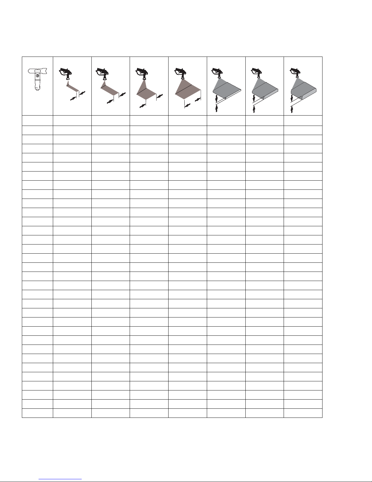
Tip Selection
ti27606a
in.
(cm)
ti27505a
in.
(cm)
ti27506a
in.
(cm)
ti27507a
in.
(cm)
ti27508a
ti27509a
Tip Selection
LL5213* 2 (5)
LL5215* 2 (5)
LL5217
LL5219
LL5315
LL5317
LL5319
LL5321
LL5323
LL5325
LL5327
LL5329
LL5331
LL5333
LL5335
LL5355
4 (10)
4 (10)
4 (10)
4 (10)
4 (10)
4 (10)
4 (10)
4 (10)
4 (10)
4 (10)
4 (10)
4 (10)
4 (10)
4 (10)
LL5417 6 (15)
LL5419 6 (15)
LL5421 6 (15)
LL5423 6 (15)
LL5425 6 (15)
LL5427 6 (15)
LL5429 6 (15)
LL5431 6 (15)
LL5435 6 (15)
LL5621 12 (30)
LL5623 12 (30)
LL5625 12 (30)
LL5627 12 (30)
LL5629 12 (30)
LL5631 12 (30)
LL5635 12 (30)
LL5639 12 (30)
ti27510a
ti27605a
*Use 100 mesh filter to reduce tip clogs.
6 3A4587B Operation, Repair, Parts

Component Identification
1
2
3
6
7
15
9 10 11
14
12 13
16
17
1
2
1516
17
3
6 7
8
14 13 12 11
18
5 4 9 10
4
5
PRIME SPRAY
ti30299a
8
Component Identification
1 Pump ON/OFF Switch
2 Pressure Control
3 Spray Gun Trigger
4 Filter
5 Pressure Gauge
6 Prime Valve
7Pump
8 Trigger Lock
9Choke
3A4587B Operation, Repair, Parts 7
10 Engine ON/OFF Switch
11 Throttle
12 Drain Hose
13 Suction Tube
14 Parking Brake
15 Adjustable Handle
16 Front Wheel Unlock/Lock
17 Adjustable Pail Holder
18 Serial ID
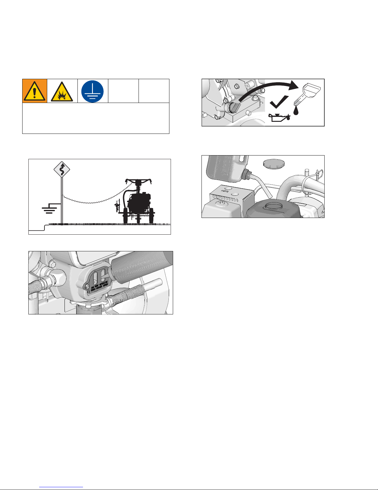
Grounding Procedure (For Flammable Materials Only)
ti24584a
ti29452a
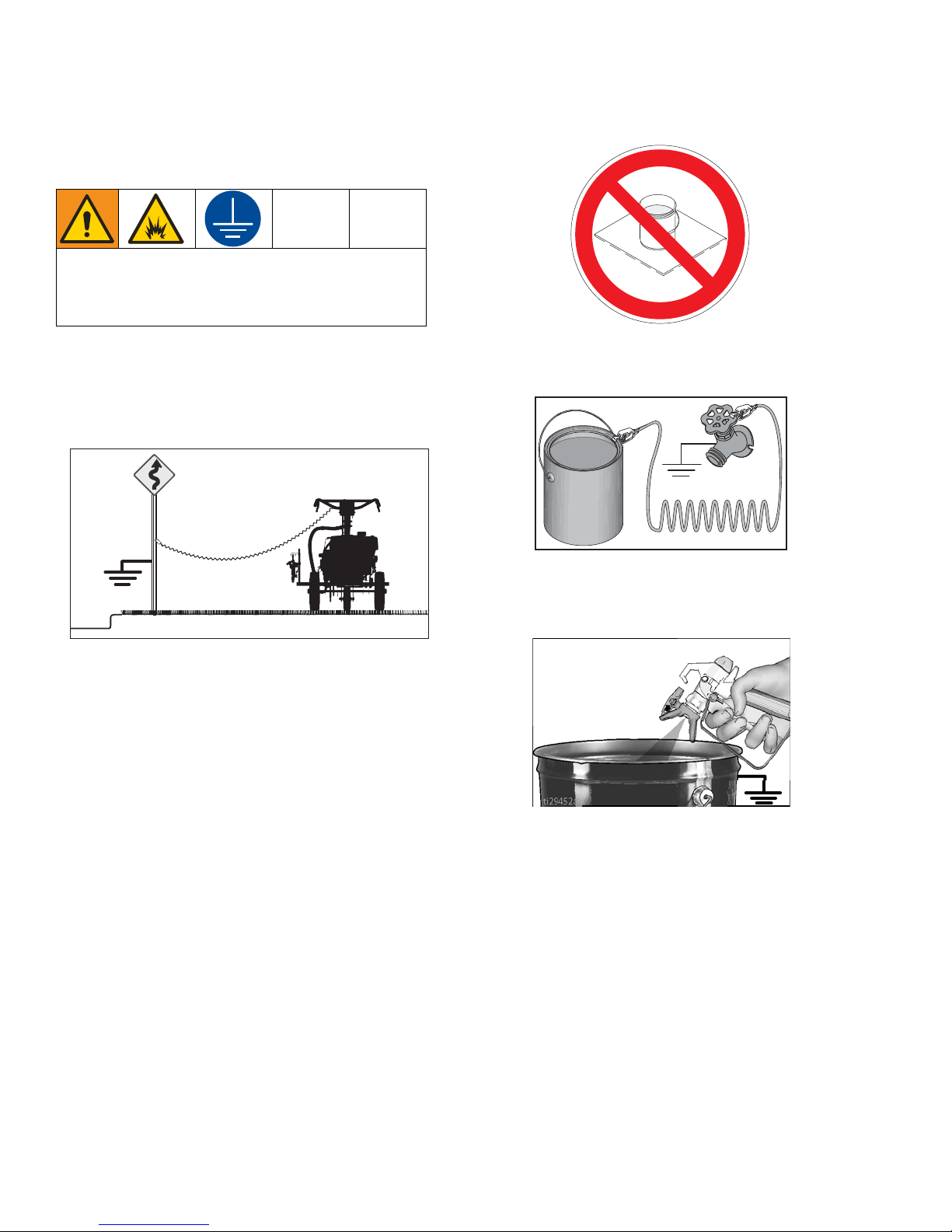
Grounding Procedure
(For Flammable Materials Only)
This equipment must be grounded to reduce the risk
of static sparking. Static sparking can cause fumes to
ignite or explode. Grounding provides an escape wire
for the electric current.
1. Position striper so that the tires are not on pavement.
2. Striper is shipped with a grounding clamp. Grounding clap must attach to grounded object. (e.g. metal
sign post).
Do not place pail on a non-conductive surface such as
paper or cardboard which interrupts grounding continuity.
Always ground a metal pail: connect a ground wire to
the pail. Clamp one end to the pail and the other end to
a true earth ground such as a water pipe.
ti30065a
Pails
Solvent and oil-based fluids: follow local code. Use
only conductive metal pails, placed on a grounded
surface such as concrete.
To maintain ground continuity when sprayer is
flushed or pressure is relieved: hold metal part of spray
gun firmly to the side of a grounded metal pail then trigger
the gun.
8 3A4587B Operation, Repair, Parts
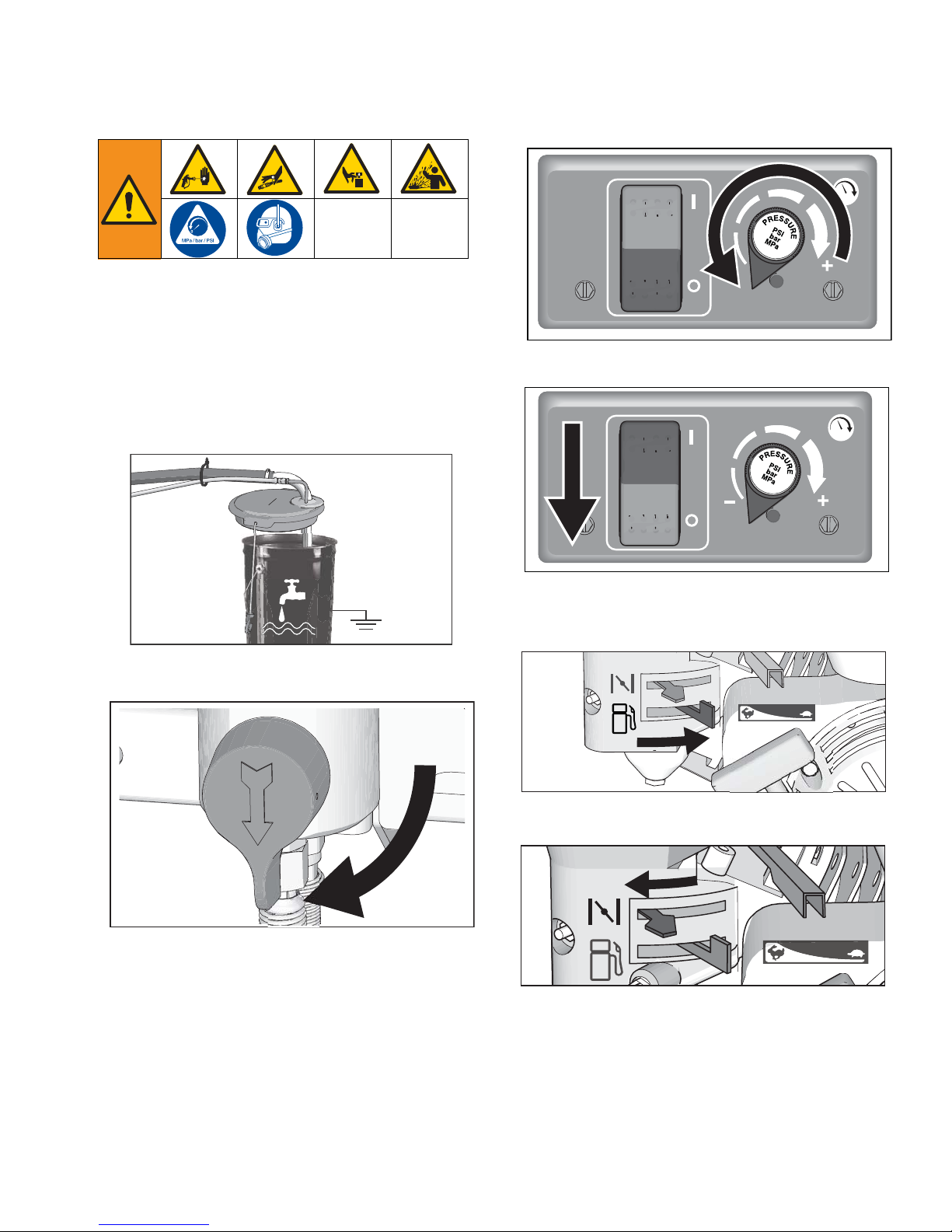
Pressure Relief Procedure
ti27504a
ti30106a
ti30107a
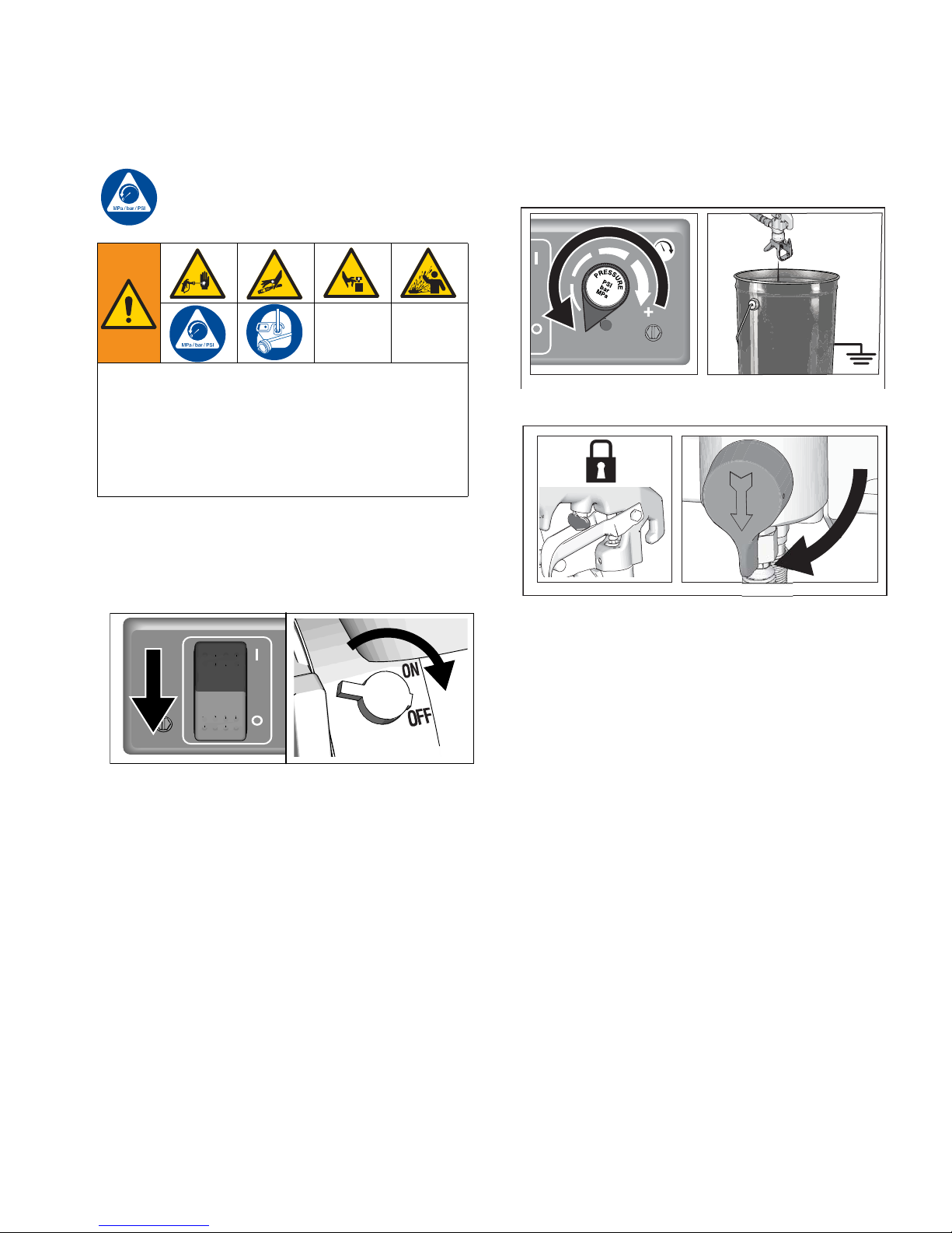
Pressure Relief Procedure
Follow the Pressure Relief Procedure
whenever you see this symbol.
This equipment stays pressurized until pressure is
manually relieved. To help prevent serious injury
from pressurized fluid, such as skin injection,
splashed fluid and moving parts, follow the Pressure
Relief Procedure whenever sprayer is stopped and
before sprayer is cleaned or checked, and before
equipment is serviced.
1. Perform Grounding Procedure if using flammable
materials.
2. Set pump switch OFF. Turn engine OFF.
3. Turn pressure to lowest setting. Trigger gun to
relieve pressure.
4. Engage the trigger lock. Turn prime valve down.
5. If you suspect the spray tip or hose is clogged or
that pressure has not been fully relieved:
a. VERY SLOWLY loosen tip guard retaining nut
or hose end coupling to relieve pressure
gradually.
b. Loosen nut or coupling completely.
c. Clear hose or tip obstruction.
3A4587B Operation, Repair, Parts 9
Pressure Relief Procedure
ti6392a
114
DAILY: Check engine oil level and fill as necessary.
DAILY: Check hose for wear and damage.
DAILY: Check gun safety for proper operation.
DAILY: Check pressure drain valve for proper opera-
tion.
DAILY: Check and fill the gas tank.
DAILY: Check level of TSL in displacement pump pack-
ing nut. Fill nut, if necessary. Keep TSL in nut to help
prevent fluid buildup on piston rod and premature wear
of packings and pump corrosion.AFTER THE FIRST 20
HOURS OF OPERATION:
Drain engine oil and refill with clean oil. Reference
Honda Engines Owner's Manual for correct oil viscosity.
WEEKLY: Remove engine air filter cover and clean element. Replace element, if necessary. If operating in an
unusually dusty environment: check filter daily and
replace, if necessary.
Replacement elements can be purchased from your
local HONDA dealer.
AFTER EACH 100 HOURS OF OPERATION:
Change engine oil. Reference Honda Engines Owner's
Manual for correct oil viscosity.
SPARK PLUG: Use only BPR6ES (NGK) or
W20EPR-U (NIPPONDENSO) plug. Gap plug to 0.028
to 0.031 in. (0.7 to 0.8 mm). Use spark plug wrench
when installing and removing plug.
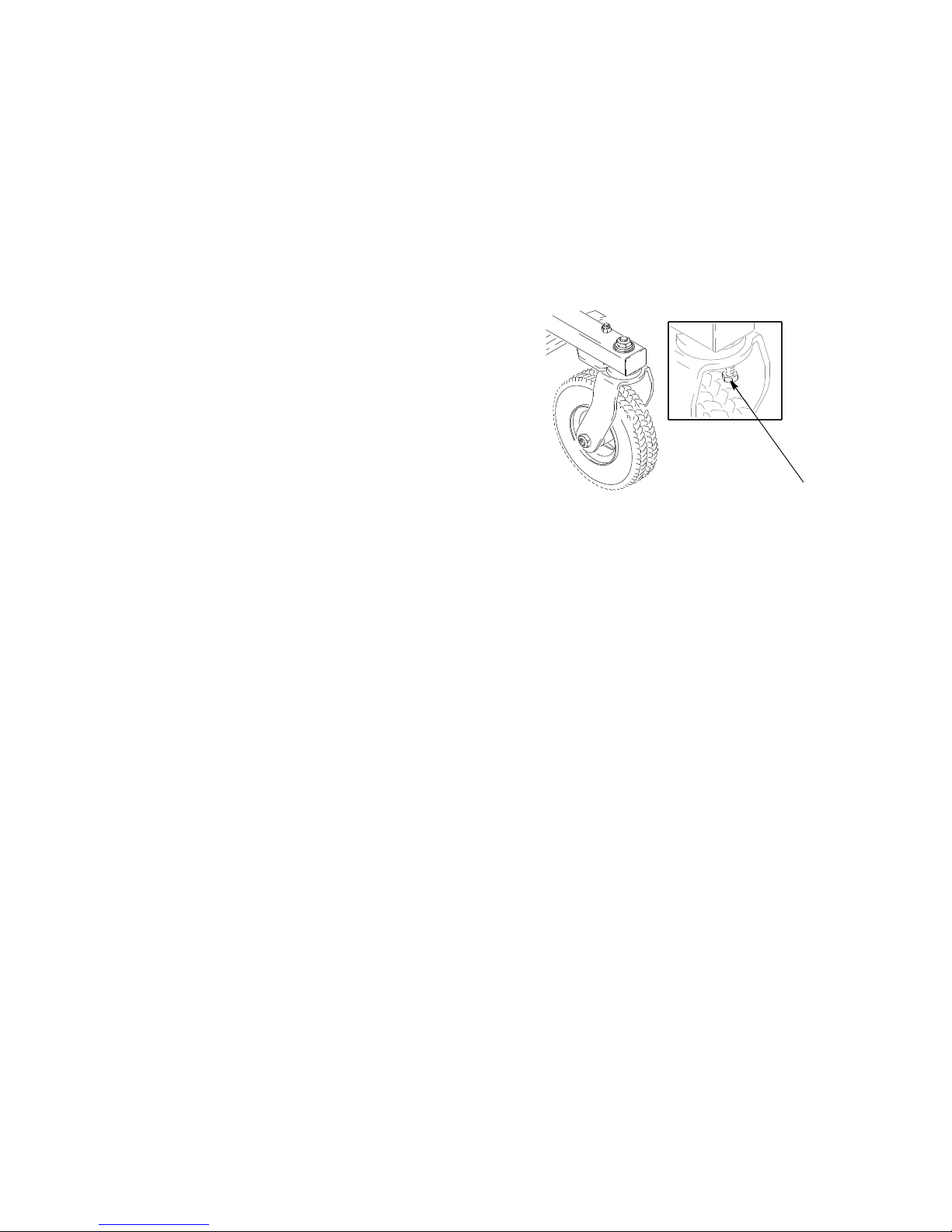
Front Wheel Alignment:
Align front wheel as follows:
1.
Loosen cap screw (114).
2. Position front wheel left or right, as necessary, to
straighten alignment.
3. Tighten cap screw (114). Push striper and let striper
roll with hands off of striper. Note: If striper rolls
straight or veers right or left. Repeat steps 1 and 2
until striper rolls straight.
10 3A4587B Operation, Repair, Parts
Operation
ti27610a
ti27611a
Operation
Setup
The equipment must be grounded to reduce the risk
of static sparking. Static sparking can cause fumes to
ignite or explode. Grounding provides an escape wire
for the electric current.
1. Ground striper with grounding clamp.
ti30065a
2. Fill throat packing nut with TSL.
3. Check engine oil level. See Honda engine manual.
4. Fill fuel tank. See Honda engine manual. Check that
tires are inflated to recommended pressure.
3A4587B Operation, Repair, Parts 11
ti30066a
Operation
ti6254b
ti6256b
ti27616b
ti30490a
Startup
1. Perform Pressure Relief Procedure. See Grounding
Procedure (For Flammable Materials Only), page
8.
2. Place siphon tube set in grounded metal pail partially
filled with flushing fluid. Attach ground wire to pail and
to true earth ground. Use water to flush water-base
paint and mineral spirits to flush oil-base paint and
storage oil.
4. Turn pressure control counterclockwise to lowest
pressure.
5. Set pump switch to OFF.
ti27613a
3. Turn prime valve down.
ti5696b
6. Start Engine.
a. Move fuel valve to open.
b. Move choke to closed.
12 3A4587B Operation, Repair, Parts
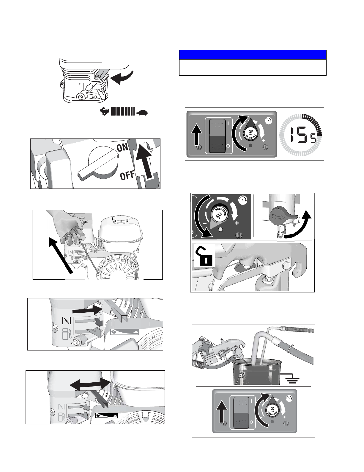
c. Set throttle to fast.
ti5250a
ti27619a
ti27620b
ti27766b
ti5250b
ti30079a
d. Set engine switch to ON.
Operation
NOTICE
Do not run pump without fluid flow. Damage to
packings can occur.
7. Set pump switch to ON. Increase pressure enough
to start pump. Allow fluid to circulate for 15 seconds.
ti30076a
8. Turn pressure down, close prime valve. Disengage
gun trigger lock.
e. Pull starter cord.
f. After engine starts, move choke to open.
g. Set throttle to slow.
ti30077a
9. Hold gun against grounded metal flushing pail. Trigger gun and increase fluid pressure slowly until
pump runs smoothly.
3A4587B Operation, Repair, Parts 13
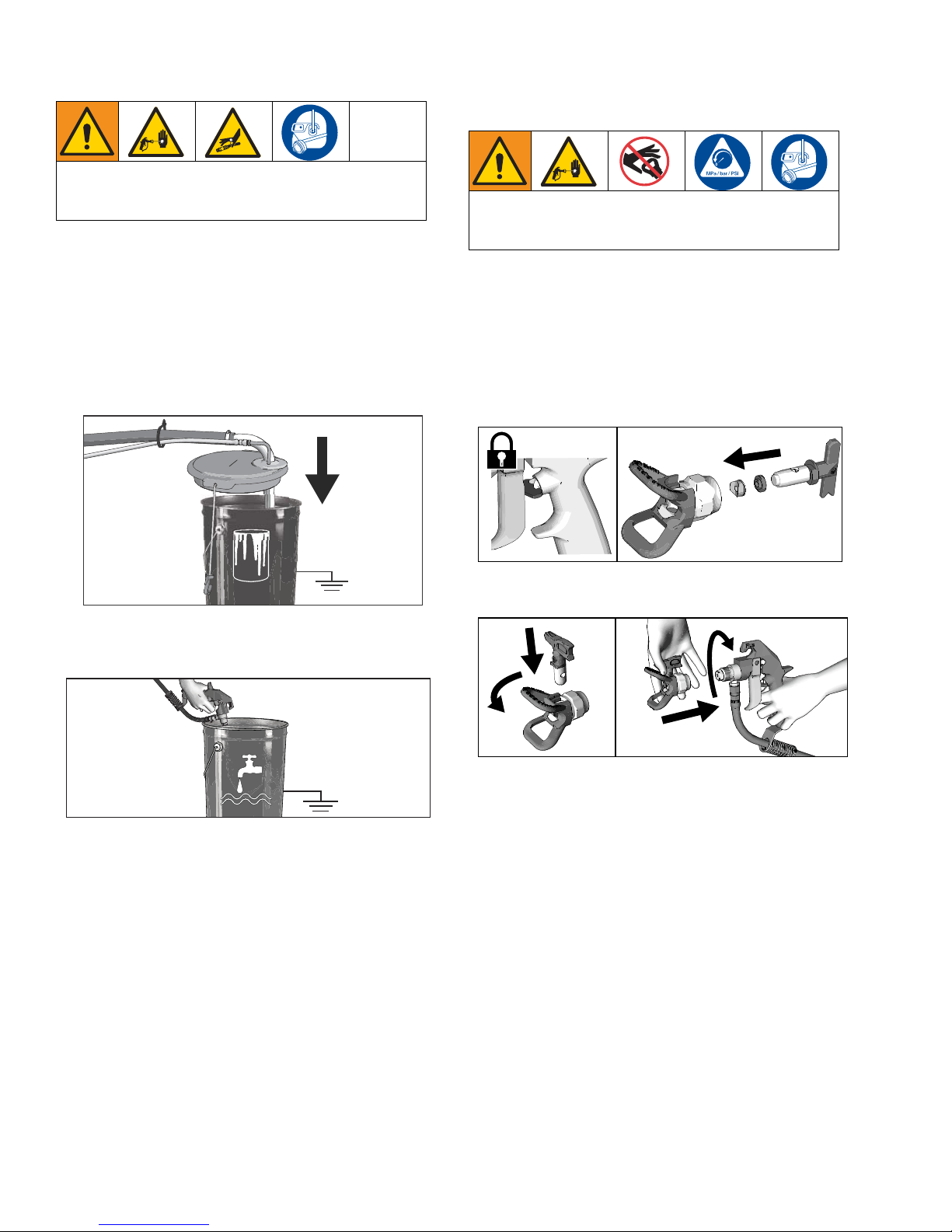
Operation
ti27775a
ti27776a
High-pressure spray is able to inject toxins into the
body and cause serious bodily injury. Do not stop
leaks with hand or rag.
10. Inspect fittings for leaks. Do not stop leaks with your
hand or a rag! If leaks occur, turn striper OFF immediately. Perform Grounding Procedure (For Flam-
mable Materials Only), page 8. Tighten leaky
fittings. Repeat Startup, steps 1 - 7. If no leaks,
continue to trigger gun until system is thoroughly
flushed. Proceed to step 8.
11. Place siphon tube in paint pail.
Rac Tip and Guard Assembly
To avoid serious injury from skin injection do not put
your hand in front of the spray tip when installing or
removing the spray tip and tip guard.
To prevent spray tip leaks, make certain spray tip and
tip guard are installed properly.
1. Perform Pressure Relief Procedure, page 8.
2. Engage trigger lock. Insert seat and Rac Tip Seal.
Insert Rac Tip.
ti27613a
12. Trigger gun again into flushing fluid pail until paint
appears. Assemble Rac Tip and Rac Guard.
ti27774a
3. Screw assembly onto gun. Hand tighten.
14 3A4587B Operation, Repair, Parts
 Loading...