

Page 1
Operation
ti28037a
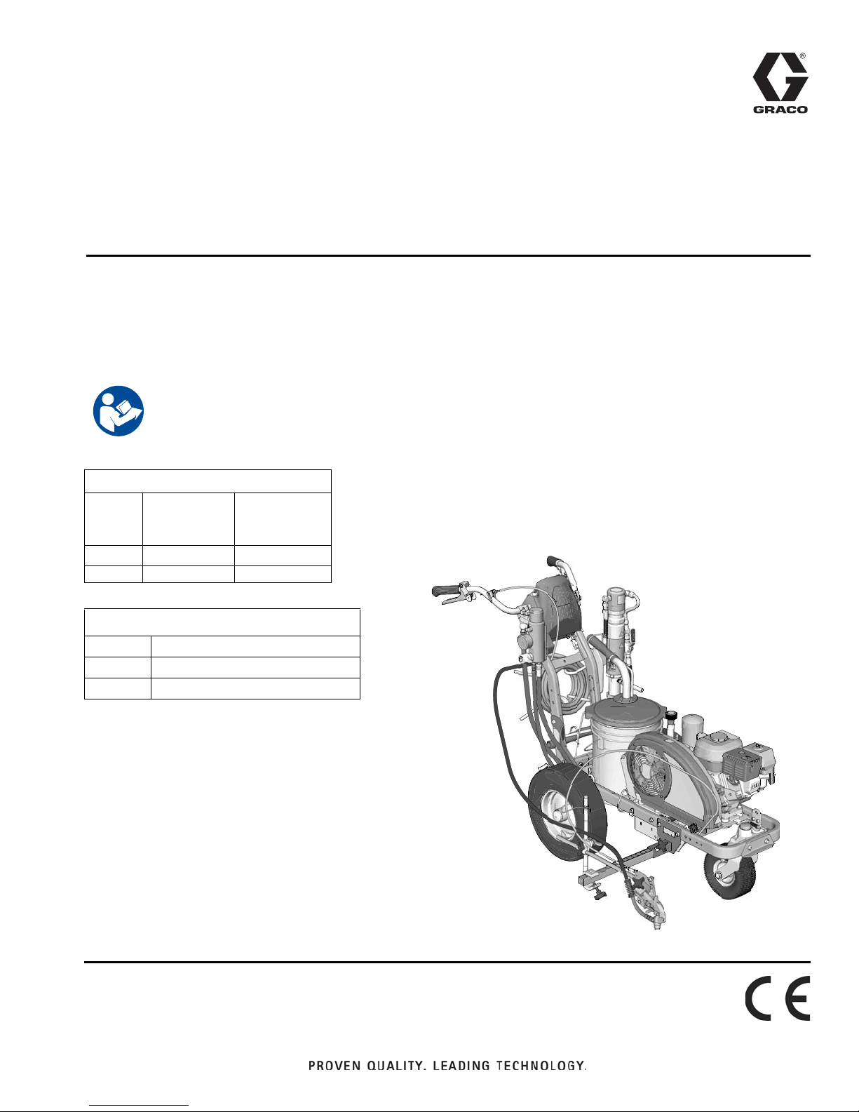
LineLazer™ 130HS Airless Line Stripers 3A3392B
EN
For the application of line striping materials.
For professional use only.
For outdoor use only.
Not for use in explosive atmospheres or hazardous locations.
Maximum Operating Pressure: 3300 psi (22.8 MPa, 228 bar)
Important Safety Instructions
Read all warnings and instructions in this manual and in related manuals.
Be familiar with the controls and the proper usage of the equipment.
Save these instructions.
LineLazer 130HS
Model: Standard
1 Manual Gun
17H447
17H448
Related Manuals:
3A3391 Parts
311254 Gun
311845 Pump
Standard
2 Manual Guns
Use only genuine Graco replacement parts.
The use of non-Graco replacement parts may void warranty.
Page 2

Table of Contents
Table of Contents
Warnings . . . . . . . . . . . . . . . . . . . . . . . . . . . . . . . . . 3
Tip Selection . . . . . . . . . . . . . . . . . . . . . . . . . . . . . . 6
Component Identification (LL 130HS) . . . . . . . . . . 7
Grounding Procedure
(For Flammable Flushing Fluids Only) . . . . . . 8
Pressure Relief Procedure . . . . . . . . . . . . . . . . . . . 8
Setup/Startup . . . . . . . . . . . . . . . . . . . . . . . . . . . . . . 9
SwitchTip and Guard Assembly . . . . . . . . . . . . 11
Gun Placement . . . . . . . . . . . . . . . . . . . . . . . . . . . 12
Install Guns . . . . . . . . . . . . . . . . . . . . . . . . . . . . 12
Position Gun . . . . . . . . . . . . . . . . . . . . . . . . . . . 12
Select Guns . . . . . . . . . . . . . . . . . . . . . . . . . . . 12
Gun Positions Chart . . . . . . . . . . . . . . . . . . . . . 13
Gun Arm Mounts . . . . . . . . . . . . . . . . . . . . . . . . 14
Change Gun Position
(Front and Back) . . . . . . . . . . . . . . . . . . . . . 14
Change Gun Position
(Left and Right) . . . . . . . . . . . . . . . . . . . . . . 15
Installation . . . . . . . . . . . . . . . . . . . . . . . . . . . . . 15
Gun Cable Adjustment . . . . . . . . . . . . . . . . . . . 15
Straight Line Adjustment . . . . . . . . . . . . . . . . . . 16
Handle Bar Adjustment . . . . . . . . . . . . . . . . . . . 16
Cleanup . . . . . . . . . . . . . . . . . . . . . . . . . . . . . . . . . . 17
Maintenance . . . . . . . . . . . . . . . . . . . . . . . . . . . . . . 18
LineLazer 130HS . . . . . . . . . . . . . . . . . . . . . . . . 18
Troubleshooting . . . . . . . . . . . . . . . . . . . . . . . . . . . 19
Hydraulic Oil/Filter Change . . . . . . . . . . . . . . . . . . 21
Removal . . . . . . . . . . . . . . . . . . . . . . . . . . . . . . 21
Installation . . . . . . . . . . . . . . . . . . . . . . . . . . . . . 21
Technical Data . . . . . . . . . . . . . . . . . . . . . . . . . . . . 22
Notes . . . . . . . . . . . . . . . . . . . . . . . . . . . . . . . . . . . . 23
Graco Standard Warranty . . . . . . . . . . . . . . . . . . . 24
2 3A3392B Operation
Page 3
Warnings
Warnings
The following warnings are for the setup, use, grounding, maintenance, and repair of this equipment. The exclamation
point symbol alerts you to a general warning and the hazard symbols refer to procedure-specific risks. When these symbols appear in the body of this manual or on warning labels, refer back to these Warnings. Product-specific hazard sym-
bols and warnings not covered in this section may appear throughout the body of this manual where applicable.
FIRE AND EXPLOSION HAZARD
Flammable fumes, such as solvent and paint fumes, in work area can ignite or explode. Paint or solvent flowing through the equipment can cause static sparking. To help prevent fire and explosion:
• Use equipment only in well ventilated area.
• Do not fill fuel tank while engine is running or hot; shut off engine and let it cool. Fuel is flammable and can
ignite or explode if spilled on hot surface.
• Eliminate all ignition sources; such as pilot lights, cigarettes, portable electric lamps, and plastic drop cloths
(potential static arc).
• Ground all equipment in the work area. See Grounding instructions.
• Never spray or flush solvent at high pressure.
• Keep work area free of debris, including solvent, rags and gasoline.
• Do not plug or unplug power cords, or turn power or light switches on or off when flammable fumes are present.
• Use only grounded hoses.
• Hold gun firmly to side of grounded pail when triggering into pail. Do not use pail liners unless they are antistatic or conductive.
• Stop operation immediately if static sparking occurs or you feel a shock. Do not use equipment until you
identify and correct the problem.
• Keep a working fire extinguisher in the work area.
SKIN INJECTION HAZARD
High-pressure spray is able to inject toxins into the body and cause serious bodily injury. In the event that
injection occurs, get immediate surgical treatment.
• Do not aim the gun at, or spray any person or animal.
• Keep hands and other body parts away from the discharge. For example, do not try to stop leaks with any
part of the body.
• Always use the nozzle tip guard. Do not spray without nozzle tip guard in place.
• Use Graco nozzle tips.
• Use caution when cleaning and changing nozzle tips. In the case where the nozzle tip clogs while spraying,
follow the Pressure Relief Procedure for turning off the unit and relieving the pressure before removing
the nozzle tip to clean.
• Equipment maintains pressure after power is shut off. Do not leave the equipment energized or under pressure while unattended. Follow the Pressure Relief Procedure when the equipment is unattended or not
in use, and before servicing, cleaning, or removing parts.
• Check hoses and parts for signs of damage. Replace any damaged hoses or parts.
• This system is capable of producing 3300 psi. Use Graco replacement parts or accessories that are rated
a minimum of 3300 psi.
• Always engage the trigger lock when not spraying. Verify the trigger lock is functioning properly.
• Verify that all connections are secure before operating the unit.
• Know how to stop the unit and bleed pressure quickly. Be thoroughly familiar with the controls.
3A3392B Operation 3
Page 4
Warnings
CARBON MONOXIDE HAZARD
Exhaust contains poisonous carbon monoxide, which is colorless and odorless. Breathing carbon monoxide
can cause death.
• Do not operate in an enclosed area.
EQUIPMENT MISUSE HAZARD
Misuse can cause death or serious injury.
• Do not operate the unit when fatigued or under the influence of drugs or alcohol.
• Do not exceed the maximum working pressure or temperature rating of the lowest rated system component. See Technical Data in all equipment manuals.
• Use fluids and solvents that are compatible with equipment wetted parts. See Technical Data in all equipment manuals. Read fluid and solvent manufacturer’s warnings. For complete information about your material, request Safety Data Sheet (SDS) from distributor or retailer.
• Do not leave the work area while equipment is energized or under pressure.
• Turn off all equipment and follow the Pressure Relief Procedure when equipment is not in use.
• Check equipment daily. Repair or replace worn or damaged parts immediately with genuine manufacturer’s
replacement parts only.
• Do not alter or modify equipment. Alterations or modifications may void agency approvals and create safety
hazards.
• Make sure all equipment is rated and approved for the environment in which you are using it.
• Use equipment only for its intended purpose. Call your distributor for information.
• Route hoses and cables away from traffic areas, sharp edges, moving parts, and hot surfaces.
• Do not kink or over bend hoses or use hoses to pull equipment.
• Keep children and animals away from work area.
• Comply with all applicable safety regulations.
PRESSURIZED ALUMINUM PARTS HAZARD
Use of fluids that are incompatible with aluminum in pressurized equipment can cause serious chemical reaction and equipment rupture. Failure to follow this warning can result in death, serious injury, or property damage.
• Do not use 1,1,1-trichloroethane, methylene chloride, other halogenated hydrocarbon solvents or fluids
containing such solvents.
• Do not use chlorine bleach.
• Many other fluids may contain chemicals that can react with aluminum. Contact your material supplier for
compatibility.
MOVING PARTS HAZARD
Moving parts can pinch, cut or amputate fingers and other body parts.
• Keep clear of moving parts.
• Do not operate equipment with protective guards or covers removed.
• Pressurized equipment can start without warning. Before checking, moving, or servicing equipment, follow
the Pressure Relief Procedure and disconnect all power sources.
ENTANGLEMENT HAZARD
Rotating parts can cause serious injury
• Keep clear of moving parts.
• Do not operate equipment with protective guards or covers removed.
• Do not wear loose clothing, jewelry or long hair while operating equipment.
• Equipment can start without warning. Before checking, moving, or servicing equipment, follow the Pres-
sure Relief Procedure and disconnect all power sources.
4 3A3392B Operation
Page 5
Warnings
TOXIC FLUID OR FUMES HAZARD
Toxic fluids or fumes can cause serious injury or death if splashed in the eyes or on skin, inhaled, or swallowed.
• Read Safety Data Sheet (SDS) to know the specific hazards of the fluids you are using.
• Store hazardous fluid in approved containers, and dispose of it according to applicable guidelines.
BURN HAZARD
Equipment surfaces and fluid that’s heated can become very hot during operation. To avoid severe burns:
• Do not touch hot fluid or equipment.
PERSONAL PROTECTIVE EQUIPMENT
Wear appropriate protective equipment when in the work area to help prevent serious injury, including eye
injury, hearing loss, inhalation of toxic fumes, and burns. This protective equipment includes but is not limited
to:
• Protective eyewear, and hearing protection.
• Respirators, protective clothing, and gloves as recommended by the fluid and solvent manufacturer.
CALIFORNIA PROPOSITION 65
The engine exhaust from this product contains a chemical known to the State of California to cause cancer,
birth defects or other reproductive harm.
This product contains a chemical known to the State of California to cause cancer, birth defects or other
reproductive harm. Wash hands after handling.
3A3392B Operation 5
Page 6

Tip Selection
ti27606a
in.
(cm)
ti27505a
in.
(cm)
ti27506a
in.
(cm)
ti27507a
in.
(cm)
ti27508a
ti27509a
ti27605a
Tip Selection
ti27510a
LL5213* 2 (5)
LL5215* 2 (5)
LL5217
LL5219
LL5315
LL5317
LL5319
LL5321
LL5323
LL5325
LL5327
LL5329
LL5331
LL5333
LL5335
LL5355
4 (10)
4 (10)
4 (10)
4 (10)
4 (10)
4 (10)
4 (10)
4 (10)
4 (10)
4 (10)
4 (10)
4 (10)
4 (10)
4 (10)
LL5417 6 (15)
LL5419 6 (15)
LL5421 6 (15)
LL5423 6 (15)
LL5425 6 (15)
LL5427 6 (15)
LL5429 6 (15)
LL5431 6 (15)
LL5435 6 (15)
LL5621 12 (30)
LL5623 12 (30)
LL5625 12 (30)
LL5627 12 (30)
LL5629 12 (30)
LL5631 12 (30)
LL5635 12 (30)
LL5639 12 (30)
*Use 100 mesh filter to reduce tip clogs.
6 3A3392B Operation
Page 7
Component Identification (LL 130HS)
8
1 3 62
7 9 10
1
3
2
5
4
6
7
8
10
9
4
5
ti28038a
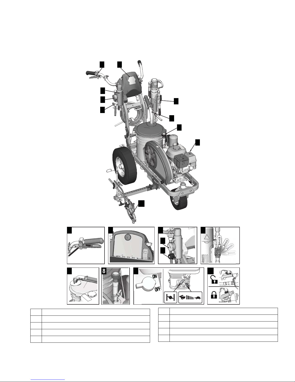
Component Identification (LL 130HS)
1 Manual spray gun trigger
2 Storage box
3 Filter
4 Pressure gauge
5 Prime/Pressure relief valve
3A3392B Operation 7
6 Pump ON/OFF lever
7 Drain and siphon tubes
8 Pressure control
9 Engine ON/OFF switch
10 Trigger safety
Page 8
Grounding Procedure (For Flammable Flushing Fluids Only)
ti23144a
ti28013a
ti27608a
Grounding Procedure
(For Flammable Flushing Fluids
Only)
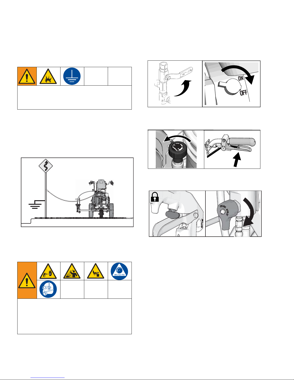
This equipment must be grounded to reduce the risk
of static sparking. Static sparking can cause fumes to
ignite or explode. Grounding provides an escape wire
for the electric current.
1. Position striper so that the tires are not on pavement.
2. Striper is shipped with a grounding clamp. Grounding clamp must attach to grounded object (e.g.
metal sign post).
1. Perform Grounding Procedure if using flammable
materials.
2. Set pump switch to OFF. Turn engine OFF.
ti27504a
3. Turn pressure control to lowest setting. Trigger all
guns to relieve pressure.
ti27615a
3. Disconnect grounding clamp after flushing is complete.
Pressure Relief Procedure
This equipment stays pressurized until pressure is
manually relieved. To help prevent serious injury
from pressurized fluid, such as skin injection, splashing fluid and moving parts, follow the Pressure Relief
Procedure when you stop dispensing and before
cleaning, checking, or servicing the equipment.
4. Engage all gun trigger locks. Turn prime valve
down.
5. If you suspect the spray tip or hose is clogged or
that pressure has not been fully relieved:
a. VERY SLOWLY loosen the tip guard retaining
nut or the hose end coupling to relieve pressure
gradually.
b. Loosen the nut or coupling completely.
c. Clear the obstruction in the hose or tip.
8 3A3392B Operation
Page 9

Setup/Startup
ti27610a
ti27611a
ti23144a
ti27612a
ti28015a
This equipment stays pressurized until pressure is
manually relieved. To help prevent serious injury
from pressurized fluid, such as skin injection, splashing fluid and moving parts, follow the Pressure Relief
Procedure when you stop spraying and before cleaning, checking, or servicing the equipment.
Setup/Startup
6. Set pump switch to OFF.
ti27504a
7. If removed, install strainer.
1. Perform
Pressure Relief Procedure
, page 8.
2. Perform Grounding Procedure (For Flammable
Flushing Fluids Only), page 8 if using flammable
materials.
3. Fill throat packing nut with Throat Seal Liquid (TSL)
to decrease packing wear.
ti28014a
4. Check engine oil level. Add SAE 10W-30 (summer)
or 5W-30 (winter). See engine manual.
8. Turn prime valve down. Turn pressure control counterclockwise to lowest pressure.
NOTE: Minimum hose size allowable for proper
sprayer operation is 3/8 in. x 22 ft for LL130
HS.
9. Place siphon tube set in grounded metal pail partially filled with flushing fluid. Attach ground wire to
true earth ground. Use water to flush water-base
paint and mineral spirits to flush oil-base paint and
storage oil.
5. Fill fuel tank.
3A3392B Operation 9
ti27613a
Page 10

Setup/Startup
ti27617a
ti5250a
ti27619a
ti27620a
ti27766a
ti5250a
10. Start engine:
a. Move fuel valve to open.
b. Move choke to closed.
c. Set throttle to fast.
ti27616a
11. After engine starts, move choke to open.
12. Set throttle to desired setting.
d. Set engine switch to ON.
e. Pull starter cord.
10 3A3392B Operation
Page 11

Setup/Startup
15s
ti28039a
ti28040a
ti28041a
ti27775a
ti27776a
13. Set pump switch to ON (pump is now active).
ti23793a
14. Increase pressure control enough to start pump.
Allow fluid to circulate for 15 seconds.
17. Inspect fittings for leaks. If leaks occur, turn sprayer
OFF immediately. Perform Pressure Relief Proce-
dure. Tighten leaky fittings. Repeat Setup/Startup,
steps 1 - 17. If no leaks, continue to trigger gun until
system is thoroughly flushed. Proceed to step 18.
18. Place siphon tube in paint pails.
ti27613a
19. Trigger all guns again into a flushing fluid pail until
paint appears. Assemble tips and guards.
15. Turn pressure down, turn prime valve horizontal.
Disengage gun trigger lock.
16. Hold all guns against a grounded metal flushing pail.
Trigger guns and increase fluid pressure slowly until
pumps run smoothly.
ti27774a
SwitchTip and Guard Assembly
1. Engage trigger lock. Use end of SwitchTip to press
OneSeal into tip guard, with curve matching tip
bore.
2. Insert SwitchTip in tip bore and firmly thread assembly onto gun.
High-pressure spray is able to inject toxins into the
body and cause serious bodily injury. Do not stop
leaks with hand or rag.
3A3392B Operation 11
Page 12

Gun Placement
ti27777a
ti27778a
ti28129a
ti28130a
1
2
ti27780a
ti27781a
ti27782a
ti27782a
Gun Placement
Install Guns
1. Insert guns into gun holder. Tighten clamps.
Position Gun
2. Position gun: up/down, forward/reverse, left/right.
See Change Gun Position (Front and Back),
page 14 and Change Gun Position (Left and
Right), page 15 for examples.
Another option can be to swing the gun out at an angle
and rotate the tip guard. This results in better visibility
for the user.
Select Guns
3. Connect gun cables to left or right gun selector
plates.
NOTE: When striping above a curb, the mounting clamp
can be rotated for clearance.
12 3A3392B Operation
a. One gun: Disconnect one gun selector plate
from trigger.
b. Both guns simultaneously: Adjust both gun
selector plates to the same position.
c. Solid-skip and skip-solid: Adjust solid-line gun
to position 1 and skip-line to position 2.
Page 13

Gun Positions Chart
1
2
3
4
5
6
7
ti27786a
Gun Placement
1 One line
2 One line up to 24 in. (61cm) wide
3 Two lines
4 One line or two lines to spray around obstacles
5 One gun curb
6 Two gun curb
3A3392B Operation 13
7 Two lines or one line up to 24 in. (61 cm) wide
Page 14

Gun Placement
ti28042a
ti27797a
ti27798a
Gun Arm Mounts
This unit is equipped with front and rear gun arm
mounts.
2. Slide gun arm assembly (including gun and hoses)
out from gun arm mounting slot.
ti27795a
3. Slide gun arm assembly into desired gun arm
mounting slot.
4. Tighten gun arm knob into gun arm mounting slot.
Change Gun Position
(Front and Back)
1. Loosen gun arm knob and remove from gun arm
mounting slot.
ti27796a
NOTICE
Make sure all hoses, cables, and wires are properly
routed through brackets and do NOT rub on tire.
Contact with tire will result in damaged hoses, cables,
and wires.
14 3A3392B Operation
Page 15

Gun Placement
ti27799a
ti27919a
ti27800a
ti28044a
Change Gun Position
(Left and Right)
Removal
1. Loosen vertical gun arm knob on gun arm mounting
bar and remove.
Installation
1. Install vertical gun mount onto gun bar.
NOTE: Make sure all hoses, cables, and wires are
properly routed through brackets.
Gun Cable Adjustment
Adjusting the gun cable will increase or decrease the
gap between the trigger plate and the gun trigger. To
adjust trigger gap, perform the steps below.
1. Use wrench to loosen locking nut on cable adjuster.
2. Extend mounting bar on opposite side of the
machine.
ti27884a
2. Loosen or tighten adjuster until desired result is
achieved. NOTE: More thread exposed means less
gap between gun trigger and trigger plate.
3. Use wrench to tighten locking nut on the adjuster.
3A3392B Operation 15
Page 16

Gun Placement
ti27810a
ti27811a
ti27812a
ti27813a
ti27814a
Straight Line Adjustment
The front wheel is set to center the unit and allow the
operator to form straight lines. Over time, the wheel may
become misaligned and will need to be readjusted. To
re-center the front wheel, perform the following steps:
1. Loosen bolt on the front wheel bracket.
2. If striper arcs to the right, loosen left set screw and
tighten right set screw for fine tune adjustment.
4. Roll the striper. Repeat steps 2 and 3 until striper
rolls straight. Tighten bolt on wheel alignment plate
to lock the new wheel setting.
Handle Bar Adjustment
3. If striper arcs to the left, loosen right set screw and
tighten left set screw.
16 3A3392B Operation
Page 17

Cleanup
TI3371A
ti6269a
TI3375A
ti3322b
This equipment stays pressurized until pressure is
manually relieved. To help prevent serious injury
from pressurized fluid, such as skin injection, splashing fluid and moving parts, follow the Pressure Relief
Procedure when you stop dispensing and before
cleaning, checking, or servicing the equipment.
1. Perform Pressure Relief Procedure, page 8.
2. Remove guard and SwitchTip from all guns.
Cleanup
4. Clean filter, guard and SwitchTip in flushing fluid.
FLUSH
5. Place siphon tube set in grounded metal pail partially filled with flushing fluid. Attach ground wire to
true earth ground. Perform Startup steps 10 - 16
(see page 10) to flush out paint in sprayer. Use
water to flush water-base paint and mineral spirits
solvent (also called white spirit) to flush oil-base
paint.
3. Unscrew cap, remove filter. Assemble without filter.
6. Hold gun against paint bucket and pull trigger until
water or solvent appears.
7. Move gun to solvent or water bucket. Hold gun
against bucket and pull trigger until the system is
thoroughly flushed.
8. Fill pump with Pump Armor and reassemble filter,
guard and SwitchTip.
9. Each time you spray and store, fill throat packing
nut with TSL to decrease packing wear.
3A3392B Operation 17
Page 18

Maintenance
Maintenance
LineLazer 130HS
Periodic Maintenance
DAILY: Check engine oil level and fill as necessary.
DAILY: Check hydraulic oil level and fill as necessary.
DAILY: Check hose for wear and damage.
DAILY: Check gun safety for proper operation.
DAILY: Check prime/spray drain valve for proper opera-
tion.
DAILY: Check and fill gas tank
DAILY: Check that displacement pump is tight.
DAILY: Top off TSL level in displacement pump packing
nut to help prevent material buildup on piston rod and
early wear of packing.
AFTER THE FIRST 20 HOURS OF OPERATION: Drain
engine oil and refill with clean oil. Reference Honda
Engines Owner’s Manual for correct oil viscosity.
Caster Wheel
1. Once each year, tighten nut under dust cap until
spring washer bottoms out, then back off the nut 1/2
to 3/4 turn.
2. Once each month, grease the wheel bearing.
3. Check pin for wear. If pin is worn out, there will be
play in the caster wheel. Reverse or replace the pin
as needed.
4. Check caster wheel alignment as necessary. To
align; page 16.
WEEKLY: Remove engine air filter cover and clean element replace, if necessary. If operating in an unusually
dusty environment, check filter daily.
WEEKLY/DAILY: Remove any debris from hydraulic
rod.
AFTER EACH 100 HOURS OF OPERATION: Change
engine oil. Reference Honda Engines Owner’s Manual
for correct oil viscosity.
SEMI-ANNUALLY: Check belt wear, replace if necessary.
YEARLY OR 2000 HOURS: Replace hydraulic oil and
filter element with Graco hydraulic oil 169236 (5 gallon/18.9 liter) or 207428 (1 gallon/3.8 liter) and filter element 246173; page 21.
SPARK PLUG: Use only BPR6ES (NGK) or
W20EPR--U (NIPPONDENSO) plug. Gap plug to 0.028
to 0.031 in (0.7 to 0.8 mm). Use spark plug wrench
when installing and removing plug.
18 3A3392B Operation
Page 19

Troubleshooting
Problem Cause Solution
Gas engine pulls hard
(won't start).
Engine won't start. Engine switch is OFF. Turn engine switch ON.
Engine operates, but displacement pump does
not operate.
Displacement pump
operates, but output is
low on upstroke
Displacement pump
operates but output is low
on downstroke and/or on
both strokes.
Hydraulic pressure is too high. Turn hydraulic pressure knob counterclockwise to
lowest setting.
Engine is out of gas. Refill gas tank. Honda Engines Owner's Manual.
Engine oil level is low. Try to start engine. Replenish oil, if necessary.
Honda Engines Owner's Manual.
Spark plug cable is disconnected or damaged. Connect spark plug cable or replace spark plug.
Cold engine. Use choke.
Fuel shutoff lever is OFF. Move lever to ON position.
Oil is seeping into combustion chamber. Remove spark plug. Pull starter 3 to 4 times.
Clean or replace spark plug. Start engine. Keep
sprayer upright to avoid oil seepage.
Pump valve is OFF. Turn pump valve ON.
Pressure setting is too low. Turn pressure adjusting knob clockwise to
increase pressure.
Fluid filter is dirty. Clean filter.
Tip or tip filter is clogged. Clean tip or tip filter. Manual 311254.
Displacement pump piston rod is stuck due to
dried paint.
Belt worn, broken or off pulley. Replace.
Hydraulic fluid too low. Shut of sprayer. Add fluid*.
Hydraulic motor not shifting. Set pump valve OFF. Turn pressure down. Turn
Piston ball is not seating. Service piston ball. Manual 311845.
Piston packings are worn or damaged. Replace packings. Manual 311845.
Strainer is clogged. Clean strainer.
O-ring in pump is worn or damaged. Replace o-ring. Manual 311845.
Intake valve ball is packed with material or is not
seating properly.
Engine speed is too low. Increase throttle setting.
Suction tube air leak. Tighten suction tube.
Pressure setting is too low. Increase pressure.
Fluid filter, tip filter or tip is clogged or dirty. Clean filter.
Large pressure drop in hose with heavy materials.
Repair pump. Manual 311845.
engine OFF. Pry rod up or down until hydraulic
motor shifts.
Clean intake valve. Manual 311845.
Use larger diameter hose and/or reduce overall
length of hose. Use of more than 100 ft of 1/4 in.
hose significantly reduces performance of
sprayer. Use 3/8 in. hose for optimum performance (22 ft minimum).
Troubleshooting
*Check hydraulic fluid level often. Do not allow it to become too low. Use only Graco approved hydraulic fluid.
3A3392B Operation 19
Page 20

Troubleshooting
Problem Cause Solution
Pump is difficult to prime. Air in pump or hose. Check and tighten all fluid connections.
Reduce engine speed and cycle pump as slowly
as possible during priming.
Intake valve is leaking. Clean intake valve. Be sure ball seat is not nicked
or worn and that ball seats well. Reassemble
valve.
Pump packings are worn. Replace pump packings. Manual 311845.
Paint is too thick. Thin the paint according to the supplier's recom-
mendations.
Engine speed is too high. Decrease throttle setting before priming pump.
High engine speed at no
load.
Low stall or run pressure
shown on display.
Excessive paint leakage
into throat packing nut.
Fluid is spitting from gun. Air in pump or hose. Check and tighten all fluid connections. Reprime
Excessive leakage
around hydraulic motor
piston rod wiper.
Fluid delivery is low. Pressure setting too low. Increase pressure.
The sprayer overheats.
Excessive hydraulic
pump noise.
Mis-adjusted throttle setting. Reset throttle to 3700-3800 engine rpm at no
load.
Worn engine governor. Replace or service engine governor.
New pump or new packings. Pump break-in period takes up to 100 gallons of
material.
Throat packing nut is loose. Remove throat packing nut spacer. Tighten throat
packing nut just enough to stop leakage.
Throat packings are worn or damaged. Replace packings. Manual 311845.
Displacement rod is worn or damaged. Replace rod. Manual 311845.
pump.
Tip is partially clogged. Clear tip. Manual 311254.
Fluid supply is low or empty. Refill fluid supply. Prime pump.Check fluid supply
often to prevent running pump dry.
Piston rod seal worn or damaged. Replace these parts.
Displacement pump outlet filter (if used) is dirty or
Clean filter.
clogged.
Intake line to pump inlet is not tight. Tighten.
Hydraulic motor is worn or damaged. Bring sprayer to Graco distributor for repair.
Large pressure drop in fluid hose. Use larger diameter or shorter hose.
Paint buildup on hydraulic components. Clean.
Oil level is low. Fill with oil.
Low hydraulic fluid level. Shut off sprayer. Add fluid*
20 3A3392B Operation
Page 21

Hydraulic Oil/Filter Change
ti2271a
Hydraulic Oil/Filter Change
Removal
This equipment stays pressurized until pressure is
manually relieved. To help prevent serious injury
from pressurized fluid, such as skin injection, splashing fluid and moving parts, follow the Pressure Relief
Procedure when you stop dispensing and before
cleaning, checking, or servicing the equipment.
1. Perform Pressure Relief Procedure, page 8.
2. Place drip pan or rags under sprayer to catch
hydraulic oil that drains out.
3. Remove drain plug. Allow hydraulic oil to drain.
4. Unscrew filter slowly - oil runs into groove and
drains out rear.
Installation
1. Apply a light film of oil on filter gasket. Install drain
plug and oil filter. Tighten oil filter 3/4 turn after gasket contacts base.
2. Fill with five quarts of Graco hydraulic oil 169236 (5
gallon/20 liter) or 207428 (1 gallon/3.8 liter).
3. Check oil level.
3A3392B Operation 21
Page 22

Technical Data
Technical Data
LineLazer 130
Engine Honda GX120cc
Maximum fluid working pressure 3300 psi (227 bar, 22.7 MPa)
Maximum free-flow delivery 1.3 gpm 4.9 lpm
Cycles per gallon/liter 85 cpg 22.5 cpl
Hydraulic reservoir capacity 1.25 gallons (4.73 liters)
Hydraulic pressure 1825 psi (124 bar)
Maximum Tip Size
1 gun 0.037 in.
2 guns 0.029 in.
Noise level (dBa)
Sound power
Sound pressure
Vibration level*
Left Hand
Right Hand
* Vibration measured per ISO 5349 bsed on 8 hr daily exposure
Inlet/Outlet Sizes
Inlet paint strainer
Outlet paint filter
Pump inlet size 1 in. npsm(m)
Fluid outlet size 3/8 npt(f)
Dimensions/Weight
Height 44.5 in. 113.03 cm
Length 68.25 in. 173.36 cm
Width 34.25 in. 87.0 cm
Weight (dry, without packaging) 263 lb 119 kg
HS
US Metric
110 dBa per ISO 3744
96 dBa measured at 3.1 feet (1m)
2.90 m/sec
2.83 m/sec
16 mesh (1190 micron) stainless steel screen, reusable
50 mesh (250 micron) stainless steel screen, reusable
2
2
Wetted parts...PTFE, Nylon, polyurethane, V-Max™
leather, tungsten carbide, stainless steel, chrome plating, nickel-plated carbon steel, ceramic
22 3A3392B Operation
Page 23

Notes
Notes
3A3392B Operation 23
Page 24

Graco Standard Warranty
Graco warrants all equipment referenced in this document which is manufactured by Graco and bearing its name to be free from defects in
material and workmanship on the date of sale to the original purchaser for use. With the exception of any special, extended, or limited warranty
published by Graco, Graco will, for a period of twelve months from the date of sale, repair or replace any part of the equipment determined by
Graco to be defective. This warranty applies only when the equipment is installed, operated and maintained in accordance with Graco’s written
recommendations.
This warranty does not cover, and Graco shall not be liable for general wear and tear, or any malfunction, damage or wear caused by faulty
installation, misapplication, abrasion, corrosion, inadequate or improper maintenance, negligence, accident, tampering, or substitution of
non-Graco component parts. Nor shall Graco be liable for malfunction, damage or wear caused by the incompatibility of Graco equipment with
structures, accessories, equipment or materials not supplied by Graco, or the improper design, manufacture, installation, operation or
maintenance of structures, accessories, equipment or materials not supplied by Graco.
This warranty is conditioned upon the prepaid return of the equipment claimed to be defective to an authorized Graco distributor for verification of
the claimed defect. If the claimed defect is verified, Graco will repair or replace free of charge any defective parts. The equipment will be returned
to the original purchaser transportation prepaid. If inspection of the equipment does not disclose any defect in material or workmanship, repairs
will be made at a reasonable charge, which charges may include the costs of parts, labor, and transportation.
THIS WARRANTY IS EXCLUSIVE, AND IS IN LIEU OF ANY OTHER WARRANTIES, EXPRESS OR IMPLIED, INCLUDING BUT NOT
LIMITED TO WARRANTY OF MERCHANTABILITY OR WARRANTY OF FITNESS FOR A PARTICULAR PURPOSE.
Graco’s sole obligation and buyer’s sole remedy for any breach of warranty shall be as set forth above. The buyer agrees that no other remedy
(including, but not limited to, incidental or consequential damages for lost profits, lost sales, injury to person or property, or any other incidental or
consequential loss) shall be available. Any action for breach of warranty must be brought within two (2) years of the date of sale.
GRACO MAKES NO WARRANTY, AND DISCLAIMS ALL IMPLIED WARRANTIES OF MERCHANTABILITY AND FITNESS FOR A
PARTICULAR PURPOSE, IN CONNECTION WITH ACCESSORIES, EQUIPMENT, MATERIALS OR COMPONENTS SOLD BUT NOT
MANUFACTURED BY GRACO. These items sold, but not manufactured by Graco (such as electric motors, switches, hose, etc.), are subject to
the warranty, if any, of their manufacturer. Graco will provide purchaser with reasonable assistance in making any claim for breach of these
warranties.
In no event will Graco be liable for indirect, incidental, special or consequential damages resulting from Graco supplying equipment hereunder, or
the furnishing, performance, or use of any products or other goods sold hereto, whether due to a breach of contract, breach of warranty, the
negligence of Graco, or otherwise.
Graco Information
For the latest information about Graco products, visit www.graco.com.
For patent information, see www.graco.com/patents.
TO PLACE AN ORDER, contact your Graco distributor or call 1-800-690-2894 to identify the nearest distributor.
All written and visual data contained in this document reflects the latest product information available at the time of publication.
GRACO INC. AND SUBSIDIARIES • P.O. BOX 1441 • MINNEAPOLIS MN 55440-1441 • USA
Copyright 2016, Graco Inc. All Graco manufacturing locations are registered to ISO 9001.
Graco reserves the right to make changes at any time without notice.
Original instructions. This manual contains English. MM 3A3392
Graco Headquarters: Minneapolis
International Offices: Belgium, China, Japan, Korea
www.graco.com
Revision
B, April 2018
 Loading...