

Graco LineDriver ES Series, LineDriver ES 25N555, LineDriver ES 25N556 Operation - Repair - Parts
Operation, Repair, Parts
LineDriver™ ES
3A6623C
For the propulsion of line striping and removal equipment. Not approved for use in
explosive atmospheres or hazardous locations. For professional use only.
Models: 25N555, 25N556
10 mph (16 kph) Maximum Operating Speed
Important Safety Instructions
Read all warnings and instructions in this manual and in related LineLazer,
GrindLazer and ThermoLazer manuals before using the equipment. Save
these instructions.
Related Manuals:
710-0138 Delta-Q Battery Charger
3A6720 Hitch Receiver Kit
LineDriver ES
EN
Model Cord Adapter
--- 25N555 North America
North America
Australia
CEE 7/7
25N556
Use only genuine Graco replacement parts.
The use of non-Graco replacement parts may void warranty.
Denmark
Italy
Switzerland
United Kingdom

Contents
Warnings . . . . . . . . . . . . . . . . . . . . . . . . . . . . . . . . . 3
Component Identification . . . . . . . . . . . . . . . . . . . . 5
Operation . . . . . . . . . . . . . . . . . . . . . . . . . . . . . . . . . 6
Setup . . . . . . . . . . . . . . . . . . . . . . . . . . . . . . . . . . 6
Startup . . . . . . . . . . . . . . . . . . . . . . . . . . . . . . . . 7
Trailer Loading & Unloading . . . . . . . . . . . . . . . . 8
Charging the Batteries . . . . . . . . . . . . . . . . . . . . 9
Maintenance . . . . . . . . . . . . . . . . . . . . . . . . . . . . . . 11
Manual Brake Adjustment or Replacement . . . 11
Throttle Linkage Adjustment . . . . . . . . . . . . . . . 12
Hitch Adjustment . . . . . . . . . . . . . . . . . . . . . . . . 13
Accelerator Calibration (Using Kit 25N880) . . . 14
Transaxle Service . . . . . . . . . . . . . . . . . . . . . . . 15
Repair . . . . . . . . . . . . . . . . . . . . . . . . . . . . . . . . . . . 16
Battery Pack Replacement . . . . . . . . . . . . . . . . 16
Battery Disposal . . . . . . . . . . . . . . . . . . . . . . . . 16
Transaxle Replacement . . . . . . . . . . . . . . . . . . 17
Traction Motor Replacement . . . . . . . . . . . . . . . 17
Motor Controller Replacement . . . . . . . . . . . . . 17
Troubleshooting - LineDriver . . . . . . . . . . . . . . . . 18
Troubleshooting - Motor Controller . . . . . . . . . . . 19
Parts Drawing . . . . . . . . . . . . . . . . . . . . . . . . . . . . . 23
Parts Drawing . . . . . . . . . . . . . . . . . . . . . . . . . . . . . 24
Parts Drawing - Detail Views . . . . . . . . . . . . . . . . . 25
Parts Drawing . . . . . . . . . . . . . . . . . . . . . . . . . . . . . 26
Parts List . . . . . . . . . . . . . . . . . . . . . . . . . . . . . . . . . 27
Wiring Diagram - Harness 25N661 . . . . . . . . . . . . 29
Wiring Diagram . . . . . . . . . . . . . . . . . . . . . . . . . . . 30
Wiring Diagram - Harness 25E406 . . . . . . . . . . . . 31
Technical Specifications . . . . . . . . . . . . . . . . . . . . 32
CALIFORNIA PROPOSITION 65 . . . . . . . . . . . 32
Graco Standard Warranty . . . . . . . . . . . . . . . . . . . 33
Graco Information . . . . . . . . . . . . . . . . . . . . . . . . . 34
2 3A6623C

Warnings
120V US
230V
Warnings
The following warnings are for the setup, use, grounding, maintenance, and repair of this equipment. The exclamation
point symbol alerts you to a general warning and the hazard symbols refer to procedure-specific risks. When these symbols appear in the body of this manual or on warning labels, refer back to these Warnings. Product-specific hazard sym-
bols and warnings not covered in this section may appear throughout the body of this manual where applicable.
GROUNDING
This product must be grounded. In the event of an electrical short circuit, grounding reduces the risk of electric shock by providing an escape wire for the electric current. This product is equipped with a cord having a
grounding wire with an appropriate grounding plug. The plug must be plugged into an outlet that is properly
installed and grounded in accordance with all local codes and ordinances.
• Improper installation of the grounding plug is able to result in a risk of electric shock.
• When repair or replacement of the cord or plug is required, do not connect the grounding wire to either flat
blade terminal.
• The wire with insulation having an outer surface that is green with or without yellow stripes is the grounding
wire.
• Check with a qualified electrician or serviceman when the grounding instructions are not completely understood, or when in doubt as to whether the product is properly grounded.
• Do not modify the plug provided; if it does not fit the outlet, have the proper outlet installed by a qualified
electrician.
• This product is for use on a nominal 120V or 230V circuit and has a grounding plug similar to the plugs illustrated below.
• Only connect the product to an outlet having the same configuration as the plug.
• Do not use an adapter with this product.
TRAFFIC HAZARD
Vehicle strikes may result in serious injury or death.
• Do not operate in traffic.
• Use traffic control.
3A6623C 3
Warnings
MOVING VEHICLE HAZARD
Careless and reckless behavior causes accidents. Falling from vehicle, running into people or object, or being
struck by other vehicles may result in serious injury or death.
•
Do not operate unless attached to line striping or line removal equipment.
•
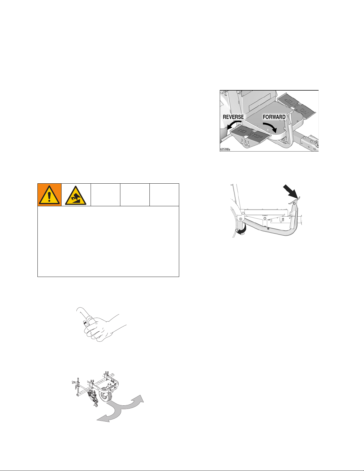
Do not step on forward/reverse pedals.
•
Make turns slowly. Do not make turns greater than 45°.
•
Loss of traction may occur going downhill.
•
Do not operate on slopes greater than 7.5°.
•
Do not carry passengers.
•
Do not tow.
•
Use with line striping or line removal equipment only.
•
Use appropriate traffic control in all traffic areas. Refer to manual on Uniform Traffic Control Devices (MUTCD), U.S.
Department of Transportation, Federal Highway Administration or local highway and transportation regulations.
ELECTRIC SHOCK HAZARD
This equipment must be grounded. Improper grounding, setup, or usage of the system can cause electric
shock.
• Turn off and disconnect power cord before servicing equipment.
• Connect only to grounded electrical outlets.
• Use only 3-wire extension cords.
• Ensure ground prongs are intact on power and extension cords.
• Do not expose to rain. Store indoors.
EQUIPMENT MISUSE HAZARD
Misuse can cause death or serious injury.
• Do not operate the unit when fatigued or under the influence of drugs or alcohol.
• Check equipment daily. Repair or replace worn or damaged parts immediately with genuine manufacturer’s
replacement parts only.
• Do not alter or modify equipment. Alterations or modifications may void agency approvals and create safety
hazards.
• Make sure all equipment is rated and approved for the environment in which you are using it.
• Use equipment only for its intended purpose. Call your distributor for information.
• Keep children and animals away from work area.
• Comply with all applicable safety regulations.
BURN HAZARD
Equipment surfaces and fluid that is heated can become very hot during operation. To avoid severe burns:
• Do not touch hot fluid or equipment.
BATTERY HAZARD
Lead-acid batteries produce explosive gases and contain sulfuric acid that can cause severe burns. To avoid
sparks and injury when handling or working with a lead-acid battery:
• Only use the battery type specified for use with the equipment. See Technical Data.
• Read and follow the battery manufacturer’s warnings.
• Exercise caution when working with metallic tools or conductors to prevent short circuits and sparks.
• Keep all sparks, flames, and cigarettes away from batteries.
• Always wear protective eyewear and protective equipment for face, hands, and body.
• If you have direct contact with battery fluid, flush with water and consult a physician immediately.
• Installation and maintenance must be performed by knowledgeable personnel only.
PERSONAL PROTECTIVE EQUIPMENT
Wear appropriate protective equipment when in the work area to help prevent serious injury, including eye
injury, hearing loss, inhalation of toxic fumes, and burns. Protective equipment includes but is not limited to:
• Protective eyewear, and hearing protection.
• Respirators, protective clothing, and gloves as recommended by the fluid and solvent manufacturer.
4 3A6623C
Component Identification
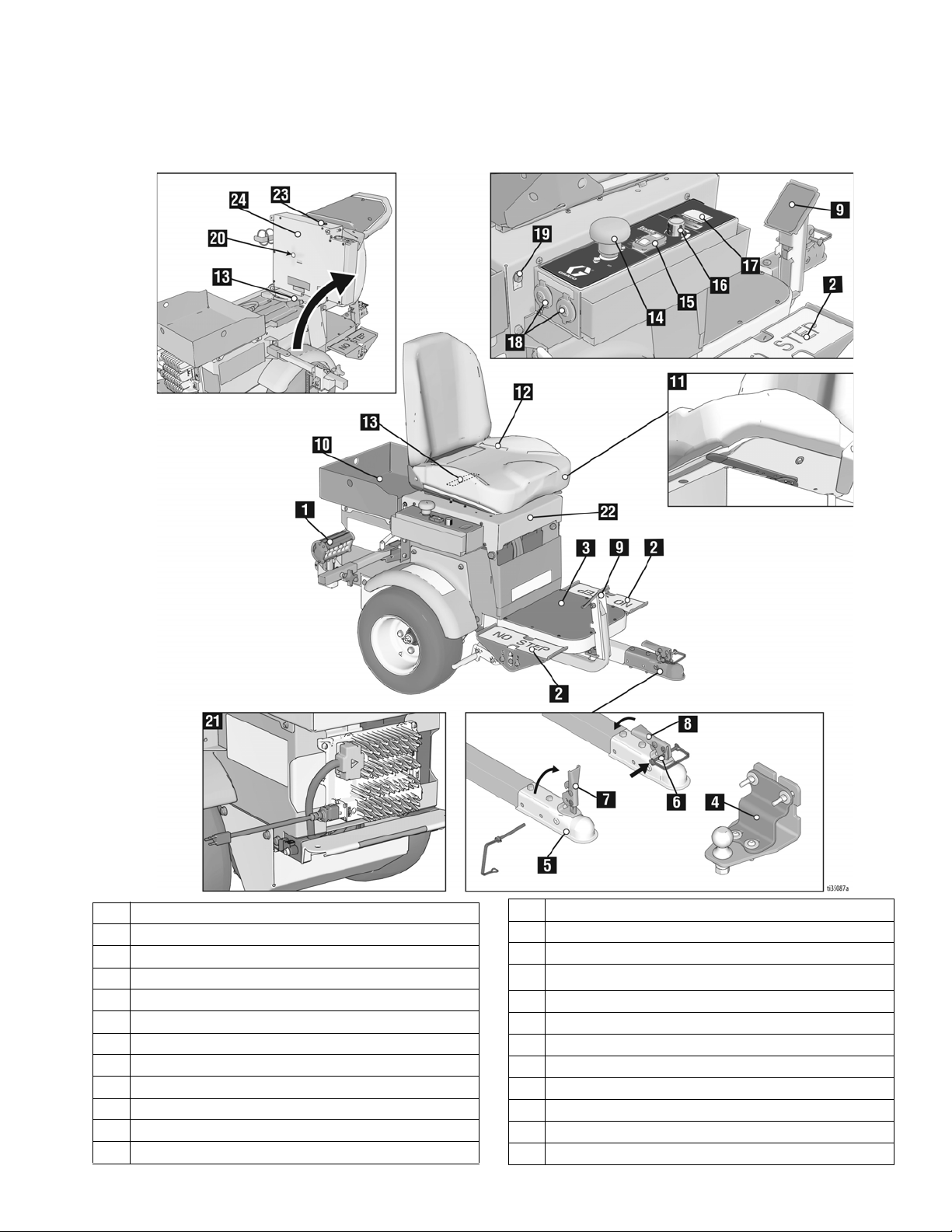
Component Identification
1 Headlight
2 Direction/Speed Pedals
3 Step Plate
4 Hitch
5 Coupler
6 Safety Pin Location
7 Handle Open
8 Handle Locked
9 Manual Brake
10 Tool Tray
11 Seat Adjustment
12 Operator Seat
3A6623C 5
13 Serial ID
14 Power Switch
15 Speed Switch
16
ExactMil
17 Voltage Meter
18 12V Aux. Power
19 Light Socket
20 Motor Controller Diagnostic Light
21 Battery Charger
22 Seat Lid
23 Buzzer
24 Seat Cover
™
Speed Control
Operation
ti11087a
ti10936a
M
ti11086a
ti11085a
Operation
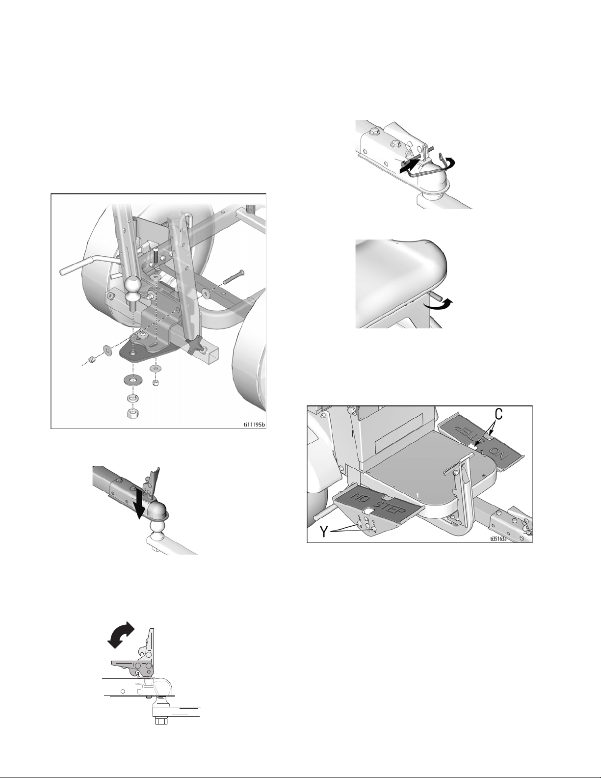
Setup
1. Install supplied ramp onto pallet.
2. Connect Hitch Receiver to line striping or line
removal equipment - Hitch Receiver Kit 25N787
Manual 3A6720.
5. Insert safety pin in latch
6. Adjust seat forward/backward with lever below seat.
7. Adjust height of pedals to desired position by
removing/replacing bolts (Y).
8. Loosen two bolts (C) on topside of pedals. Rotate
pedal to desired position. Tighten bolts.
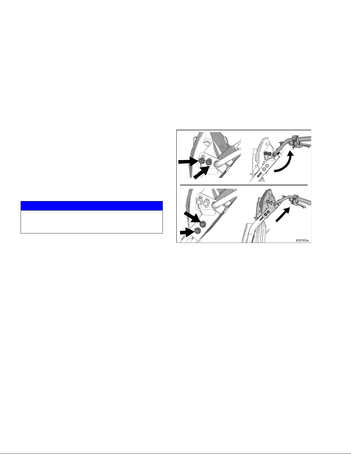
3. Install LineDriver coupler to striper or grinder hitch
ball.
4. Latch coupler to locked position (M).
NOTE: If coupler is too tight to latch or is loose after
latching, coupler needs adjustment. Refer to Hitch
Adjustment, page 13.
9. Continue onto Startup, page 7.
6 3A6623C
Operation
ti10937a
ti10935a
ti11009a
Startup
1. Check battery charge level. Charge if not fully
charged.
2. Sit on seat to actuate safety switch. Ensure pedals
are not depressed.
3. Disengage Manual Brake on LineDriver and
attached equipment.
4. Turn power switch ON. Buzzer will sound in a few
seconds.
5. Operate control to release attached equipment.
NOTE: Interlocks in the LineDriver control system
remove drive power if the Power Switch is OFF, the
Direction/Speed Pedals are engaged when switching
power ON, or the driver lifts themself off the seat.
FREEWHEEL HAZARD
Loss of drive power causes LineDriver to freewheel,
which allows it to roll freely.
• Stay fully seated in the driver’s seat while operating the LineDriver.
• If loss of drive power occurs while LineDriver is in
motion, use the Manual Brake to bring LineDriver
to a stop.
• Always engage Manual Brake before turning
Power Switch OFF or standing up from seat.
7. Move pedals to drive LineDriver, as shown below.
Switching from forward to reverse creates a braking
action.
NOTE: LineDriver stops when both feet are removed
from pedals.
8. Set Manual Brake when not operating LineDriver.
This prevents rolling when on an incline.
Operating on an Incline
• Engage the Manual Brake before turning the Power
Switch to OFF when parking on an incline.
NOTE: LineDriver motion is forward and reverse. Turns
are made with the striper or grinder.
• Turn the Power Switch to ON and allow the machine
to initialize before releasing the Manual Brake when
starting on an incline.
Enable ExactMil
™
Speed Control
ExactMil ensures a consistent paint thickness by holding
the speed steady.
6. Push striper or grinder handle bars to begin desired
turn.
1. Stop moving. Turn speed control knob all the way
counterclockwise.
2. Set Speed Switch to ExactMil position.
3. Depress foot pedal to go forward. Adjust speed control knob to desired speed setting.
NOTE: ExactMil speed control is only active when moving forward. Reverse speed is not impacted. ExactMil
speed control limits the maximum speed that can be
obtained with the pedal.
3A6623C 7
Operation
Disable ExactMil Speed Control
• Return Speed Switch to center position.
Enable ECO Mode
ECO Mode can be compared to half-throttle on a gas
powered unit. It is helpful when greater control is
needed, such as loading and unloading, driving in congested areas, and operating on slopes. It also extends
battery life.
• Set Speed Switch to ECO position.
NOTE: ECO Mode limits forward speed to 4 mph and
reverse speed to 2.6 mph.
Disable ECO Mode
• Return Speed Switch to center position.
12V Auxiliary Ports
• 12V auxiliary power ports are provided to power
accessories.
NOTICE
12V auxiliary ports must be used to power accessories.
Battery damage can result if other means are used to
power accessories.
Trailer Loading & Unloading
1. Always keep LineDriver connected to striper or
grinder.
2. Use a level surface to load and unload. Leave sufficient space behind ramps.
3. Use loading ramps sufficiently long and capable of
handling weight of unit and operator.
4. Adjust striper or grinder handlebar to highest position. Slide seat back as far as possible.
5. Use right foot to engage Manual Brake. Use left foot
to control speed. Use ECO Mode to limit speed.
6. Slowly drive straight up/down ramps (do not drive at
an angle).
7. Keep a firm grip on handlebars as the ramp is negotiated.
NOTE: Striper or grinder handlebars swing up/down as
the ramp is engaged/disengaged. Keep legs clear.
NOTE: Check Manual Brake clearance to tire and tire
pressure to ensure they are adjusted properly. Refer to
Manual Brake Adjustment or Replacement, page 11.
8 3A6623C
Operation
Charging the Batteries
Replace and charge battery only in well-ventilated
area and away from flammable or combustible materials, including paints and solvents. The charger may
become hot while charging. Do not touch. Refer to
Charger Manual for additional information.
The charger may be used any time the LineDriver is not
being used. When the batteries are fully charged, the
charger automatically stops. If the LineDriver is stored
for an extended period, the batteries may self-discharge
enough for the charger to automatically recharge the
batteries. For optimum battery life, always leave the
charger plugged in.
NOTICE
Lead acid batteries can self-discharge in as little as 3
months depending on storage temperatures. The hotter
the storage temperature, the faster the self-discharge
occurs. To prevent damage to the battery, it is important to keep the battery in a charged state.
Batteries are fully charged when leaving the factory.
Due to self-discharging of the battery, charge battery
before first use. It takes ~18 hours to charge a fully
depleted battery, and ~8 hours to charge the battery 3/4
full.
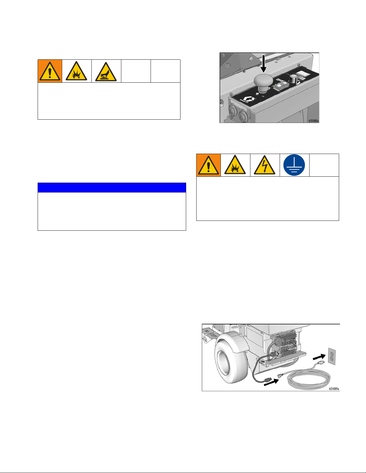
3. Ensure power switch is in OFF position.
4. Plug charging cord into charging port on the unit.
Connect an extension cord, per charger manual, to
the charging cord and plug it into wall power.
This equipment must be grounded to reduce the risk
of static sparking and electric shock. An electric
shock or static spark can cause fumes to ignite or
explode. An improper ground can cause electric
shock. A good ground provides an escape wire for
the electric current.
Always use an outlet that is properly installed and
grounded in accordance with all local codes and ordinances.
Do not modify the plug provided; if it does not fit the
outlet, have the proper outlet installed by a qualified
electrician.
NOTE: Battery life depends on the depth of discharge
per cycle. A battery that is discharged to 50% depth will
get over twice as many cycles in its life compared to it
being discharged to 100% depth each cycle.
1. Place unit in dry, well-ventilated area and away from
flammable or combustible materials, including
paints and solvents.
2. Position the driver so the wheels are on a true
grounded surface, not on pavement.
3A6623C 9
Power Requirements
• All models use the same battery charger. Refer to
Technical Specifications, page 32, for power
requirements.
Operation
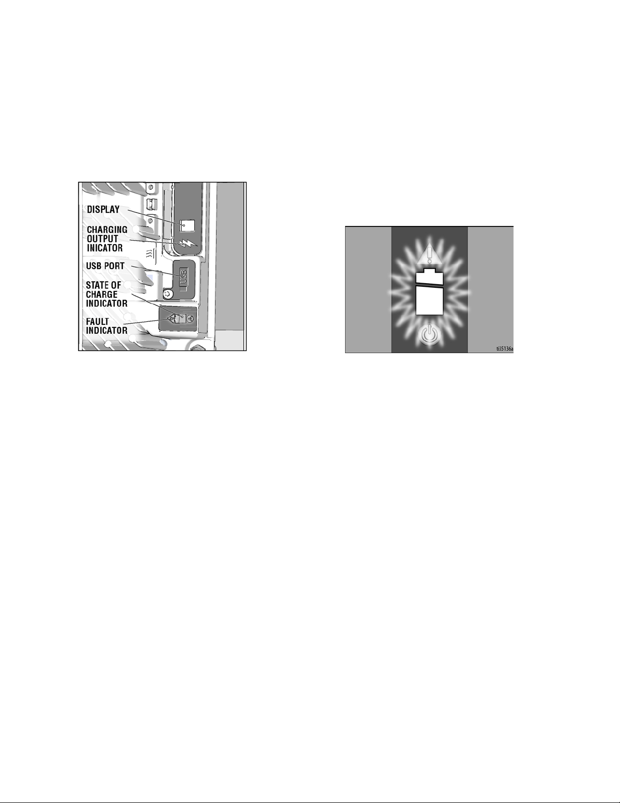
DISPLAY
CHARGING
OUTPUT
INICATOR
USB PORT
STATE OF
CHARGE
INDICATOR
FAULT
INDICATOR
ti35137a
5. The Charging Output Indicator means that the charger output is active.
6. When power is connected, charger will immediately
begin charging.
NOTE: Battery will charge to ~30 volts while charging
and then it will come back down to ~27 volts after fully
charging.
NOTE: The Charge Display may show codes to indicate
different conditions. Refer to charger manual for addi-
tional information.
• ‘F’ codes meaning that an internal fault condition
has caused charging to stop.
• ‘E’ codes meaning that an external error condition
has caused charging to stop.
7. When battery charge indicator is solid green, the
charge is complete.
10 3A6623C
Maintenance
Maintenance
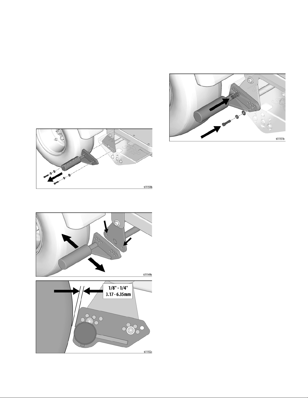
Manual Brake Adjustment or
Replacement
1. Block tires so LineDriver will not move. Release
Manual Brake.
2. Ensure power switch is in OFF position.
3. Inflate tires to operating pressure per tire sidewall.
Remove two bolts securing brake rod.
4. Select a hole pattern that positions the brake rod 1/8
to 1/4 in. from the tire.
5. Install two bolts and secure brake rod. Repeat for
second tire.
NOTE: Brake rods are not interchangeable from side to
side. Model shown in the graphic above is the right side
version.
3A6623C 11
 Loading...