

Page 1
Instructions - Parts
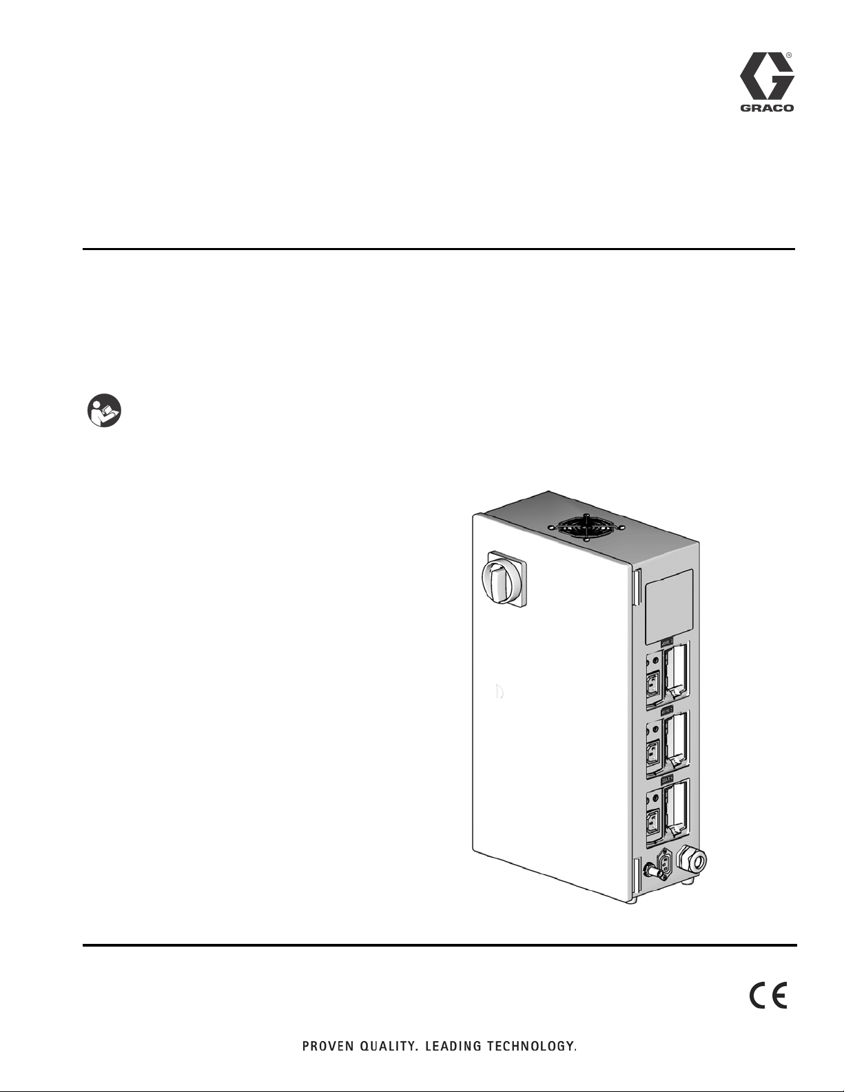
PR70 and PR70v
Integrated Heat
For controlling material temperature in heated tanks and hoses.
Models LC0250, LC0251,
LC0252, LC0253
Important Safety Instructions
Read all warnings and instructions in all supplied manuals. Save these instructions.
312761B
Assembly LC0252 Shown
ti12577a
Page 2
Supplied Manuals
Contents
Supplied Manuals . . . . . . . . . . . . . . . . . . . . . . . . . . 2
Warnings . . . . . . . . . . . . . . . . . . . . . . . . . . . . . . . . . 3
Component Identification . . . . . . . . . . . . . . . . . . . 4
Grounding . . . . . . . . . . . . . . . . . . . . . . . . . . . . . . . . 5
Installation . . . . . . . . . . . . . . . . . . . . . . . . . . . . . . . . 5
Connect Electrical Cord . . . . . . . . . . . . . . . . . . . 5
Install Low Power Temperature Control Modules 6
Connect 3-wire Module Power . . . . . . . . . . . . . . 6
Adjust Rotary Switch . . . . . . . . . . . . . . . . . . . . . . 7
Setup . . . . . . . . . . . . . . . . . . . . . . . . . . . . . . . . . . . . . 8
Cable Connections . . . . . . . . . . . . . . . . . . . . . . . 8
Operation . . . . . . . . . . . . . . . . . . . . . . . . . . . . . . . . 10
Maintenance . . . . . . . . . . . . . . . . . . . . . . . . . . . . . . 10
Install Upgrade Token . . . . . . . . . . . . . . . . . . . . 10
Clean . . . . . . . . . . . . . . . . . . . . . . . . . . . . . . . . . 10
Troubleshooting . . . . . . . . . . . . . . . . . . . . . . . . . . . 11
Circuit Breaker . . . . . . . . . . . . . . . . . . . . . . . . . 11
Diagnostic Information . . . . . . . . . . . . . . . . . . . 11
Simplified Wiring Schematic . . . . . . . . . . . . . . . 11
Wiring Schematic . . . . . . . . . . . . . . . . . . . . . . . 12
Parts . . . . . . . . . . . . . . . . . . . . . . . . . . . . . . . . . . . . 14
Circuit Breakers . . . . . . . . . . . . . . . . . . . . . . . . . 17
Technical Data . . . . . . . . . . . . . . . . . . . . . . . . . . . . 19
Dimensions . . . . . . . . . . . . . . . . . . . . . . . . . . . . 19
Graco Ohio Standard Warranty . . . . . . . . . . . . . . 20
Graco Ohio Information . . . . . . . . . . . . . . . . . . . . 20
Supplied Manuals
Assemblies with a Standard Display Module
include manual 312393. Assemblies with an
Advanced Display Module include manuals 312759
and 312760.
PR70 and PR70v Operation and Parts Manuals
Part Description
312393 PR70 with Standard Display Module Opera-
tion and Maintenance Manual
312759 PR70 and PR70v with Advanced Display
Module Operation and Maintenance Manual
312760 PR70 and PR70v with Advanced Display
Module Repair and Parts Manual
MD2 Dispense Valve Manual
Part Description
312185 MD2 Dispense Valve Instructions and Parts
Manual
PR70 and PR70v Feed Systems Manual
Part Description
312394 PR70 and PR70v Feed Systems Manual
PR70 and PR70v Integrated Heat Manual
Part Description
312761 PR70v Integrated Heat Instructions - Parts
Manual
2 312761B
Page 3
Warnings
Warnings
The following warnings are for the setup, use, grounding, maintenance, and repair of this equipment. The exclamation point symbol alerts you to a general warning and the hazard symbol refers to procedure-specific risk. Refer back
to these warnings. Additional, product-specific warnings may be found throughout the body of this manual where
applicable.
WARNING
ELECTRIC SHOCK HAZARD
This equipment must be grounded. Improper grounding, setup, or usage of the system can cause electric shock.
Equipment With Grounding Plug
• Turn off and disconnect power cord before servicing equipment.
• Use only grounded electrical outlets.
• Use only 3-wire extension cords.
• Ensure ground prongs are intact on power and extension cords.
• Do not expose to rain. Store indoors.
Hard-Wired Equipment
• Turn off and disconnect power at main switch before disconnecting any cables and before servicing
equipment.
• Connect only to grounded power source.
• All electrical wiring must be done by a qualified electrician and comply with all local codes and regulations.
EQUIPMENT MISUSE HAZARD
Misuse can cause death or serious injury.
• Do not operate the unit when fatigued or under the influence of drugs or alcohol.
• Do not exceed the maximum working pressure or temperature rating of the lowest rated system
component. See Technical Data in all equipment manuals.
• Use fluids and solvents that are compatible with equipment wetted parts. See Technical Data in all
equipment manuals. Read fluid and solvent manufacturer’s warnings. For complete information
about your material, request MSDS forms from distributor or retailer.
• Check equipment daily. Repair or replace worn or damaged parts immediately with genuine manufacturer’s replacement parts only.
• Do not alter or modify equipment.
• Use equipment only for its intended purpose. Call your distributor for information.
• Route hoses and cables away from traffic areas, sharp edges, moving parts, and hot surfaces.
• Do not kink or over bend hoses or use hoses to pull equipment.
• Keep children and animals away from work area.
• Comply with all applicable safety regulations.
312761B 3
Page 4
Component Identification
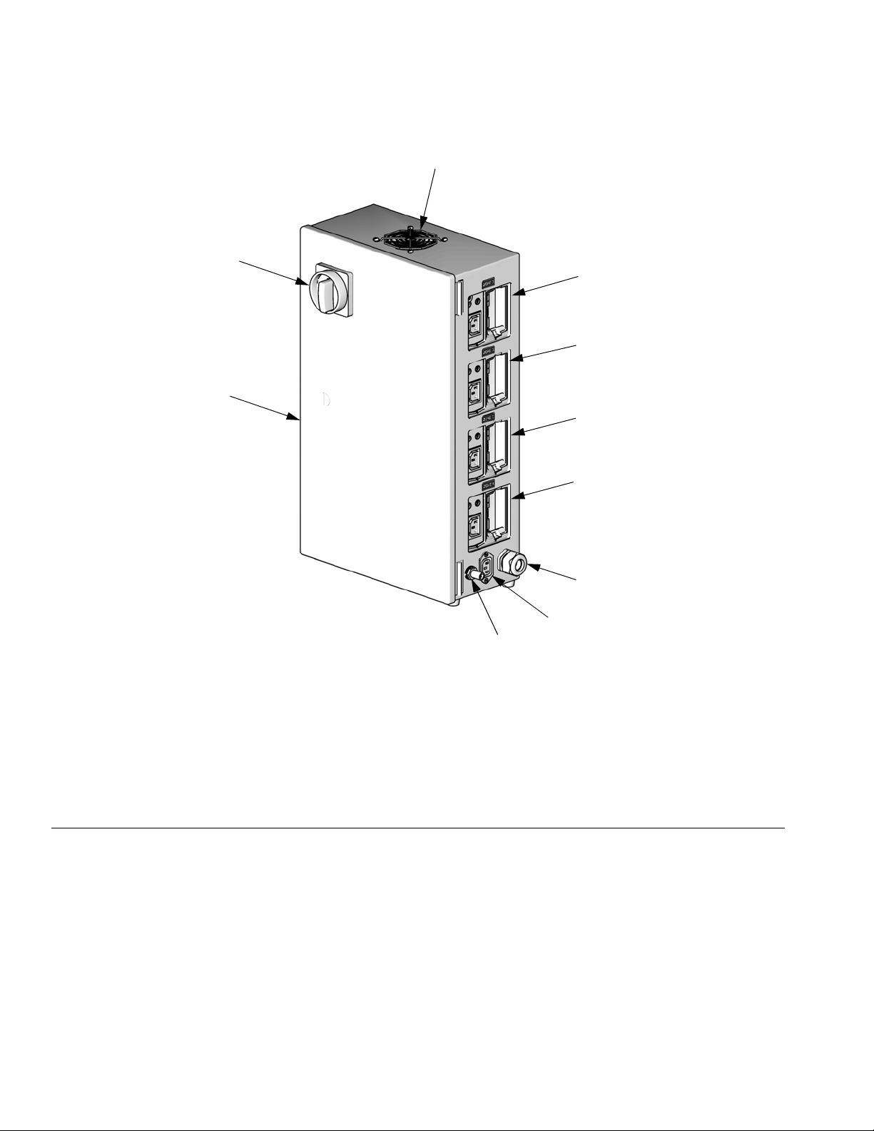
Component Identification
AE
AK
AF
AD
AC
AB
Assembly LC0253 Shown
FIG. 1: Heat Control Box
Key:
AA Zone 1
AB Zone 2
AC Zone 3
AD Zone 4
AE Electrical Disconnect Switch
AF Fan
AA
AG
ti12577a
AH
AJ
AG Integrated Heat Power Inlet
AH Integrated Heat Power Outlet
to Machine
AJ CAN Connection Output to
Machine
AK Heat Control Box
4 312761B
Page 5

Grounding
Grounding
This product must be grounded. In the event of an electrical short circuit, grounding reduces the risk of electric
shock by providing an escape wire for the electric current. This product is equipped with a chord having a
grounding wire. A 3-blade grounding plug must be
installed or the machine may be hard wired. The plug
must be plugged into an outlet that is properly installed
and grounded in accordance with all local codes and
ordinances.
Improper installation of the grounding plug is able to
result in a risk of electric shock. The wire with insulation
having an outer surface that is green with or without yellow stripes is the grounding wire. Do not modify the plug
provided; if it does not fit the outlet, have the proper outlet installed by a qualified electrician. Only connect the
product to an outlet having the same configuration as
the plug. Do not use an adapter with this product.
Installation
Connect Electrical Cord
appropriate gauge wire for the machine amperage.
See the following table.
Number of Zones
installed in Heat
Control Box
1 30 10 (2.59) / 3
2 30 10 (2.59) / 3
3 40 8 (3.26) / 3
4 40 8 (3.26) / 3
Install Plug
The equipment must be grounded. Grounding
reduces the risk of static and electric shock by providing an escape wire for the electrical current due to
static build up or in the event of a short circuit.
Improper installation of the grounding plug is able to
result in a risk of electric shock. The wire with insulation having an outer surface that is green with or without yellow stripes is the grounding wire.
2.
For machines that will not be hard-wired,
3-blade 240V, 1-phase grounding plug onto
cord (129). The machine must use a receptacle that
accepts the plug on the product.
For machines that will be hard-wired,
the machine. The grounding wire must be used.
Rating
(Amps)
Gauge (mm
Number of Wires
2
) /
install a
hard-wire
Machine may be hard-wired or installed using a
plug.
Improper wiring may cause electric shock or other
serious injury if work is not performed properly. Have
a qualified electrician perform any electrical work. Be
sure your installation complies with all National, State
and Local safety and fire codes.
1. Each machine comes with a permanent 10 ft power
cable without a plug. If a permanent extension cable
must be installed onto the existing cable or if an
extension cord is necessary, be sure to use the
312761B 5
Page 6
Installation
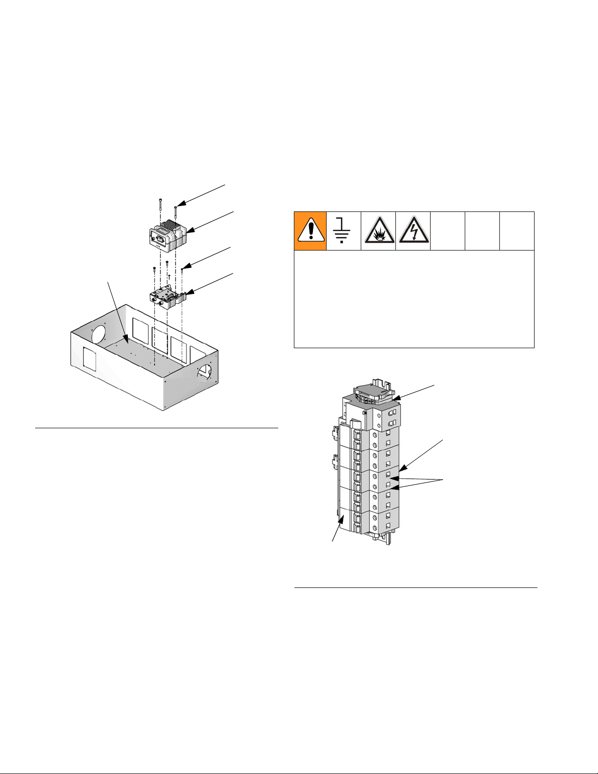
Install Low Power Temperature Control Modules
The low power temperature control modules are
installed in the Heat Control box at the factory. If a low
power temperature control module must be replaced,
perform the following procedure.
124a
124
119
120
125
8. Use two hex head cap screws (124a) to install low
power module (124) onto base module (125).
9. Change rotary switch position on new low power
temperature control module. See Adjust Rotary
Switch on page 7.
10. Reconnect CAN cables (113, 130) and power
cables.
Connect 3-wire Module Power
Connecting the power must be performed by a qualified electrician. The equipment must be grounded.
Grounding reduces the risk of static and electric shock
by providing an escape wire for the electrical current
due to static build up or in the event of a short circuit.
The wire with insulation having an outer surface that is
green with or without yellow stripes is the grounding
wire.
ti12703a
FIG. 2
Remove Old Low Power Temperate Control Module
1. On units with a grounding plug, unplug unit from
wall.
On hard-wired units, use facility power switch to
turn off incoming power.
2. Unplug data connection and power cables from low
power temperature control modules. Do not disconnect other end of cables.
3. Remove hex head cap screws (124a) from low
power temperature control module.
4. Remove low power module (124).
5. Remove four socket head cap screws (119).
6. Remove base module (125).
4
3
2
1
Main Power
Breaker
F
IG. 3: Breaker Numbering
116
141
141a
ti12627b
Install New Low Power Temperate Control Module
7. Use four socket head cap screws (119) to install
base module (125) onto enclosure back
panel (120).
6 312761B
Page 7

Installation
There is one breaker for each heated hose or heated
tank. The lower number breakers are used for the
heated tanks if installed. See F
IG. 3. For example, if
there are two heated tanks installed and two heated
hoses, breakers #1 and #2 are used for the heated
tanks and breakers #3 and #4 are used for the heated
hoses. If there is one heated tank and one heated hose,
then breaker #1 is used for the heated tank and breaker
#2 is used for the heated hose. Each breaker has a different rating so it is important that the correct breaker is
used.
The 3-wire module power is connected in the Heat Control box at the factory. The power cord (118) for each low
power temperature control module has a connector on
one end and three power leads on the other. The three
power leads must be connected to the appropriate
breaker (114) and ground terminal (116).
1. Connect the power cord connector to the low power
temperature control module.
2. Connect the green wire to any unused ground terminal block (116).
Set the rotary switch (S) to the specific selection according to the settings listed in the following table.
Low Power Temperature Control Module
Rotary Switch Location
S
ti12361a
F
IG. 4
Low Power Temperature Control Module
Rotary Switch Settings
3. Find the breaker with the same number as the module as shown in F
IG. 3 on page 6 and FIG. 6 on
page 9.
4. Connect the black and white wires to the
breaker (141) labeled with the same number as the
module. The black and white wires can connect to
either terminal (141a) in the same breaker (141).
Adjust Rotary Switch
The rotary switch setting must only be adjusted on
new low power temperature control modules after
installation.
The rotary switch setting indicates which zone number
the low power temperature control module will control in
the system. The low power temperature control module
uses a 16-position rotary switch.
The modules must always be set to the zone number shown on the label above the module.
Switch
Setting Zone
11
22
33
44
312761B 7
Page 8

Setup
Setup
Cable Connections
3
ti12356a
1
2
5
6
4
ti12357a
F
IG. 5: Low Power Temperature Control Module Cable Connections
1 Overtemperature Switch Connection
2 RTD Temperature Sensor Connection
3 Output Power Connection
4 DC Output Connection
5 Input Power Connection
6 CAN Connections
7Base
The overtemperature switch connection (1), RTD temperature sensor connection (2), and output power
connection (3) connect to the respective components of
a temperature control option. The display module must
be updated to specify which zone number is used with
which temperature control option. See the PR70 and
PR70v Operation manual referenced at the beginning of
this manual for more information.
7
8 312761B
Page 9

Data Cable Connections
130
130
130
Setup
4
3
2
1
ti12625a
113
F
IG. 6: Data Cable Connections
The low power temperate control modules must be connected together using the female-female CAN
cables (130) as shown in F
IG. 6. Then they must be con-
nected to the display module using the female-male
CAN cable (113).
312761B 9
Page 10

Operation
Operation
See the PR70 and PR70v Operation manual referenced
at the beginning of this manual for operating instructions.
Maintenance
Install Upgrade Token
1. Ensure system is inactive and control power is on.
2. Remove access cover (C).
C
4. Press and hold the left red token upload button (M)
for three seconds. The red indicator light (L) will
flash up to three seconds after the software is
uploaded.
5. Remove token (T).
6. Replace access cover (C).
7. Repeat procedure for all low power temperature
control modules.
8. Turn machine power off then on after all modules
are upgraded.
Clean
Keep heat sink fins clean at all times. Wipe the fins
clean with a dry cloth or clean them using compressed
air.
Do not use conductive cleaning solvents on the low
power temperature control modules.
ti12358a
F
IG. 7: Remove Access Cover
3. Insert and press token (T) firmly into slot.
There is no preferred orientation of token.
L
S
ti12359a
T
M
F
IG. 9: Clean Heat Sink Fins
Heat Sink Fins
ti12357a
F
IG. 8: Install Token
10 312761B
Page 11

Troubleshooting
Circuit Breaker
If the circuit breaker is tripped, manually flip the breaker
back to the “on” position. Find and correct the problem
before continuing operation.
Diagnostic Information
Module Status LEDs
7
Table 1: LED Status Signal
Signal Description
Troubleshooting
Green on Low power temperature control mod-
ule is powered up.
Yellow Internal communication in progress.
Red solid Low power temperature control mod-
ule failure.
Red flashing Software is updating.
Simplified Wiring Schematic
208-240V
50/60 Hz
1 phase
GFEP
Breaker #1
Circuit
FIG. 10: LED Signals
Circuit
Breaker #2
Circuit
Breaker #3
Circuit
Breaker #4
LED
Signals
ti12357a
Circuit
Breaker #5
Low Power
Fan
312761B 11
Temp Cont
Module #1
Low Power
Temp Cont
Module #2
Low Power
Temp Cont
Module #3
Low Power
Temp Cont
Module #4
Machine
Power
Page 12

Troubleshooting
Wiring Schematic
2
GFPE 112
1
NN
FIG. 11: Wiring Schematic, Page 1 of 2
12 312761B
Page 13

Troubleshooting
FIG. 12: Wiring Schematic, Page 2 of 2
312761B 13
Page 14

Parts
Parts
118
108, 107
121
124
105
117
102
101
130
144
104
103
127
128
119
125
126
120
113
132
114
129
115
135
134
116
133
135
102
106
146
145
1
1
1
141
116
115
123
131
117
110
122
136
198
121
ti12471b
111
1
14 312761B
112
Heated hose and heated tank circuit breakers shown for reference only. See
Circuit Breakers on page 17 for part numbers.
109
102
Assembly LC0252 Shown
Page 15

LC0253
LC0250
Control Box, Heat,
Ref Description
101 GUARD, fan,
80 mm x 80 mm
102 SCREW, panhead
machined
103 NUT, lock, hex 105334 105334 105334 105334 4
104 FAN, brushless,
80 x 80 x 25, 24 VDC
105 CONNECTOR, straight,
M8, 3-PIN, solder
106 SWITCH, disconnect,
3-pole, 40A
107 SHAFT, disconnect, elec-
tric
108 HANDLE, disconnect,
electric
109 FILTER, screen, fan, 80
mm x 80 mm
110 SCREW 120916 120916 120916 120916 2
111 FOOT, BUMPER 123698 123698 123698 123698 4
112 SCREW 120885 120885 120885 120885 4
113 CABLE, CAN, male /
female, 0.4 m
114 CONNECTOR, thru,
M12, male / female
115 BLOCK, end stop, termi-
nal, tan, 35 mm RA
116 BLOCK, terminal, spg,
4P, ground, 600V/20A
117 CORD, power, v-lock,
C14/C13, 10A
118 CORD, power, v-lock,
15P/C13, 10A
119 SCREW, socket head
cap, 10-32 x 0.62, stain-
less steel
120 PANEL, back, enclosure,
12 in.
PANEL, back, enclosure,
20 in.
121 ENCLOSURE,
12 x 12 x 6, 2 load
ENCLOSURE,
20 x 12 x 6, 4 load
122 GRIP, cord,
0.51 - 0.71, 3/4
GRIP, cord,
0.35 - 0.63, 3/4
123 SCREW, pan head
machined,
M5 - 0.8 x 12 mm
124 MODULE, low power,
Graco Control Architec-
ture
125 MODULE, Graco Control
Architecture, base
1 Load, 240V
121560 121560 121560 121560 1
105676 105676 105676 105676 10
121556 121556 121556 121556 1
121590 121590 121590 121590 1
121568 121568 121568 121568 1
121149 121149 121149 121149 1
121148 121148 121148 121148 1
121559 121559 121559 121559 1
121226 121226 121226 121226 1
121612 121612 121612 121612 1
123384 123384 123384 123384 2
123686
(Qty 3)
121599
(Qty 2)
121598
(Qty 1)
113003
(Qty 4)
121584 121584
121563 121563
121603 121603
121725 121725 121725 121725 2
256270
(Qty 1)
289697
(Qty 1)
LC0251
Control Box, Heat,
2 Load, 240V
123686
(Qty 3)
121599
(Qty 3)
121598
(Qty 2)
113003
(Qty 8)
256270
(Qty 2)
289697
(Qty 2)
LC0252
Control Box, Heat,
3 Load, 240V
123686
(Qty 4)
121599
(Qty 4)
121598
(Qty 3)
113003
(Qty 12)
121585 121585 1
121565 121565 1
121171 121171 1
256270
(Qty 3)
289697
(Qty 3)
Control Box,
Heat, 4 Load,
240V Qty
123686
(Qty 4)
121599
(Qty 5)
121598
(Qty 4)
113003
(Qty 16)
256270
(Qty 4)
289697
(Qty 4)
Parts
1
1
1
312761B 15
Page 16

Parts
LC0253
LC0250
Control Box, Heat,
Ref Description
126 † COVER, heat box 15U672 15U672 1
127 NUT, hex 110911
128 WASHER, plain #10 120907 120907 2
129 CORD, 10/3, 40A,
SOOW, CU, 600V
CORD, 8/3, 30A, SOOW,
CU, 600V
130 CABLE, CAN, 90 female /
90 female
131 RAIL, DIN 514014
132 GASKET, enclosure,
heat, Graco Control
Architecture
133 CONNECTOR, bus bar, 2
phase, 4 poles
CONNECTOR, bus bar, 2
phase, 6 poles
CONNECTOR, bus bar, 2
phase, 8 poles
CONNECTOR, bus bar, 2
phase, 10 poles
134 TERMINAL 121648 121648 121648 121648 2
135 CAP 121649 121649 121649 121649 2
136 CONNECTOR, power,
panel mount
137 LABEL, zone1 15V283 15V283 15V283 15V283 1
138 LABEL, zone2 15V284 15V284 15V284 1
139 LABEL, zone3
140 LABEL, zone4 15V286 1
141 CIRCUIT, breaker, 2-pole,
10A, C type
142† ENCLOSURE, Graco
Control Architecture, door
143 CABLE, CAN, M12 x
M12, 5P, female / female,
straight x right angle
144 TERMINAL, ring, #8
AWG, 1/4 in. stud
145 CIRCUIT, breaker, 63A,
GFI
146 BRACKET, disconnect,
40A
197†
198 PLATE, legend, serial
199†
LABEL, electric shock
number
PLUG, retainer
1 Load, 240V
065054 065054
(Qty 0.6)
121566
(Qty 1)
15U740 1
121558 121558 121558 121558 1
121634 121634 121634 121634 1
277674
(Qty 1)
121685 121685 121685 121685 1
123421 123421 123421 123421
123687 123687 123687 123687
16C235 16C235 16C235 16C235
XXXXX XXXXX XXXXX XXXXX
293564 293564 293564 293564
123699 123699 123699 123699
LC0251
Control Box, Heat,
2 Load, 240V
121597
(Qty 1)
514014
(Qty 0.83)
121566
(Qty 2)
15U741 1
277674
(Qty 2)
LC0252
Control Box, Heat,
3 Load, 240V
110911 2
121158 121158 12
121597
(Qty 2)
514014
(Qty 0.83)
121566
(Qty 3)
15U742 1
15V285 15V285 1
277674
(Qty 3)
Control Box,
Heat, 4 Load,
240V Qty
121597
(Qty 3)
514014
(Qty 0.83)
121566
(Qty 4)
15U743 1
277674
(Qty 4)
12
1
1
1
1
1
1
† Part not shown.
Replacement Danger and Warning labels, tags, and cards are available at no cost.
16 312761B
Page 17

Parts
Circuit Breakers
See the PR70 and PR70v Repair - Parts manual referenced at the beginning of this manual to find the heated
hose and heated tank assembly numbers for your system.
Heated Hose Circuit Breakers
Installed Heated
Hose Package Circuit Breaker
LC0881 121630
LC0882 121631
LC0883 121632
LC0884 121630
LC0885 121631
LC0886 121632
LC0887 121630
LC0888 121631
LC0889 121632
LC0890 121632
LC0891 121633
LC0190 121630
LC0191 121631
LC0192 121632
LC0193 121630
LC0194 121631
LC0195 121632
LC0196 121630
LC0197 121631
LC0198 121632
LC0199 121632
LC0200 121633
LC0201 121630
LC0202 121631
LC0203 121632
LC0204 121630
LC0205 121631
LC0206 121632
LC0207 121630
LC0208 121631
LC0209 121632
LC0210 121632
LC0211 121633
Heated Tank Assembly Circuit Breakers
Installed Heated
Tank Assembly Circuit Breaker
LC0237
LC0238
LC0254
LC0255
LC0259
LC0260
121633
121635
312761B 17
Page 18

Parts
18 312761B
Page 19

Technical Data
Technical Data
Electrical Power . . . . . . . . . . . . . . . . . . . . . . . . . . . . . . . . 208-240V 50/60 Hz, 1 phase for heat - 10 kW max.
(Qty 4) 2500W outputs
Weight . . . . . . . . . . . . . . . . . . . . . . . . . . . . . . . . . . . . . . . 30 lb (13.6 kg) - 1 and 2 Zone Models
50 lb (22.7 kg) - 3 and 4 Zone Models
Dimensions
C
A
Assembly LC0253 Shown
F
IG. 13: Dimensions
1 and 2 Zone
Assemblies
Ref
A (height) 12 (305) 20 (508)
B (width) 12 (305) 12 (305)
C (depth) 6 (152) 6 (152)
in. (mm)
3 and 4 Zone
Assemblies
in. (mm)
ti12626a
B
ti12628a
312761B 19
Page 20

Graco Ohio Standard Warranty
Graco warrants all equipment referenced in this document which is manufactured by Graco and bearing its name to be free from defects in
material and workmanship on the date of sale to the original purchaser for use. With the exception of any special, extended, or limited warranty
published by Graco, Graco will, for a period of twelve months from the date of sale, repair or replace any part of the equipment determined by
Graco to be defective. This warranty applies only when the equipment is installed, operated and maintained in accordance with Graco’s written
recommendations.
This warranty does not cover, and Graco shall not be liable for general wear and tear, or any malfunction, damage or wear caused by faulty
installation, misapplication, abrasion, corrosion, inadequate or improper maintenance, negligence, accident, tampering, or substitution of
non-Graco component parts. Nor shall Graco be liable for malfunction, damage or wear caused by the incompatibility of Graco equipment with
structures, accessories, equipment or materials not supplied by Graco, or the improper design, manufacture, installation, operation or
maintenance of structures, accessories, equipment or materials not supplied by Graco.
This warranty is conditioned upon the prepaid return of the equipment claimed to be defective to an authorized Graco distributor for verification of
the claimed defect. If the claimed defect is verified, Graco will repair or replace free of charge any defective parts. The equipment will be returned
to the original purchaser transportation prepaid. If inspection of the equipment does not disclose any defect in material or workmanship, repairs will
be made at a reasonable charge, which charges may include the costs of parts, labor, and transportation.
THIS WARRANTY IS EXCLUSIVE, AND IS IN LIEU OF ANY OTHER WARRANTIES, EXPRESS OR IMPLIED, INCLUDING BUT NOT LIMITED
TO WARRANTY OF MERCHANTABILITY OR WARRANTY OF FITNESS FOR A PARTICULAR PURPOSE.
Graco’s sole obligation and buyer’s sole remedy for any breach of warranty shall be as set forth above. The buyer agrees that no other remedy
(including, but not limited to, incidental or consequential damages for lost profits, lost sales, injury to person or property, or any other incidental or
consequential loss) shall be available. Any action for breach of warranty must be brought within two (2) years of the date of sale.
GRACO MAKES NO WARRANTY, AND DISCLAIMS ALL IMPLIED WARRANTIES OF MERCHANTABILITY AND FITNESS FOR A
PARTICULAR PURPOSE, IN CONNECTION WITH ACCESSORIES, EQUIPMENT, MATERIALS OR COMPONENTS SOLD BUT NOT
MANUFACTURED BY GRACO. These items sold, but not manufactured by Graco (such as electric motors, switches, hose, etc.), are subject to
the warranty, if any, of their manufacturer. Graco will provide purchaser with reasonable assistance in making any claim for breach of these
warranties.
In no event will Graco be liable for indirect, incidental, special or consequential damages resulting from Graco supplying equipment hereunder, or
the furnishing, performance, or use of any products or other goods sold hereto, whether due to a breach of contract, breach of warranty, the
negligence of Graco, or otherwise.
FOR GRACO CANADA CUSTOMERS
The Parties acknowledge that they have required that the present document, as well as all documents, notices and legal proceedings entered into,
given or instituted pursuant hereto or relating directly or indirectly hereto, be drawn up in English. Les parties reconnaissent avoir convenu que la
rédaction du présente document sera en Anglais, ainsi que tous documents, avis et procédures judiciaires exécutés, donnés ou intentés, à la suite
de ou en rapport, directement ou indirectement, avec les procédures concernées.
Graco Ohio Information
For the latest information about Graco products, visit www.graco.com.
TO PLACE AN ORDER,
Toll Free: 1-800-746-1334 or Fax: 330-966-3006
All written and visual data contained in this document reflects the latest product information available at the time of publication.
contact your Graco distributor or call to identify the nearest distributor.
Graco reserves the right to make changes at any time without notice.
This manual contains English. MM 312761
Graco Headquarters: Minneapolis
International Offices: Belgium, China, Japan, Korea
GRACO OHIO INC. 8400 PORT JACKSON AVE NW, NORTH CANTON, OH 44720
Copyright 2008, Graco Ohio Inc. is registered to I.S. EN ISO 9001
www.graco.com
Rev 9/2009
 Loading...