

Page 1
Instructions-Parts
3A0293C
Air Controls
Air controls for light and heavy duty Xtreme Sprayer carts. For professional use only.
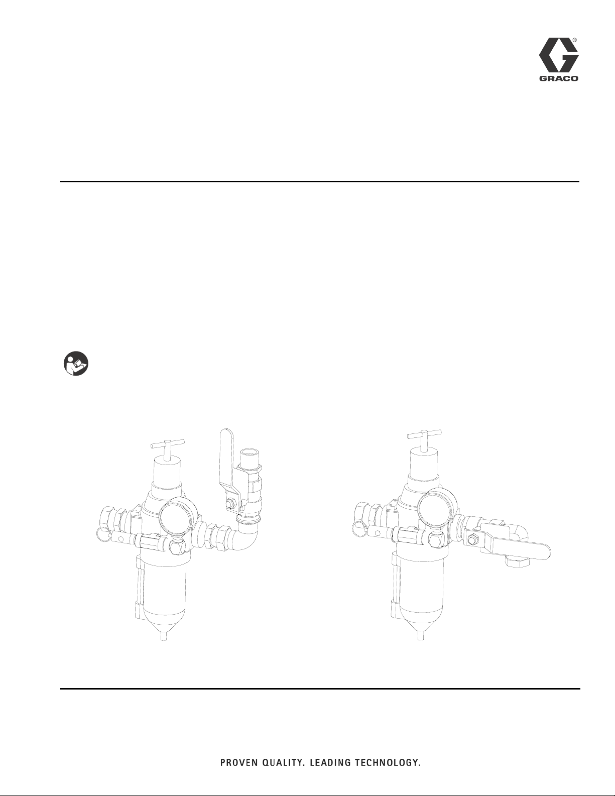
24E025
Air Controls for Light Duty Xtreme Package Carts
24E013
Air Controls for Heavy Duty Xtreme Package Carts
100 psi (0.7 MPa, 7 bar) Maximum Working Pressure
ENG
Important Safety Instructions
Read all warnings and instructions in this manual
and the Xtreme Packages manual. Save these
instructions.
24E025 24E013
r_24e025_3A0293_1a
r_24e013_3A0293_1a
Page 2
Installation
Installation
Prepare the Site
NOTE: Always use Genuine Graco Parts and Accessories, available from your Graco distributor. If you
supply your own accessories, be sure they are adequately sized and pressure rated for your system.
Bring a compressed air supply line from the air compressor to the pump location. Be sure all air hoses are
properly sized and pressure-rated for your system. Use
only electrically conductive hoses. The air hose should
have a 3/4 npsm(m) thread. Before installing any air line
components, blow out the air lines to remove scale and
other debris. Use pipe compound or tape sparingly and
only on male threads.
Install a bleed-type shutoff valve in the air line upstream
from all other air line components, to isolate them for
servicing.
Kit Components (page 7)
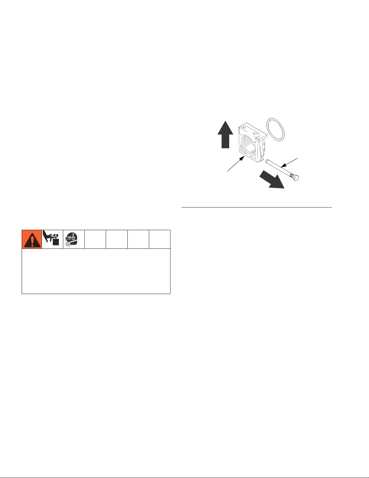
Using the Pipe Port Inserts
To open the pipe port insert (A), remove the insert pin
(S) and pull insert up in direction away from pin hole.
Install new insert and reinsert pin.
S
A
ti1249a
FIG. 1
Use the bleed-type master air valve (3) to relieve air
trapped between it and the pump when the valve is
closed. This helps reduce the risk of serious injury,
including fluid injection and splashing of fluid in the
eyes or on the skin, and injury from moving parts if
you are adjusting or repairing the pump.
Bleed-Type Master Air Valve (3)
Relieve air trapped between it and the air motor when
the valve is closed. Be sure the bleed valve is easily
accessible from the pump, and is located downstream
from the air filter/regulator (1). F
Air Filter/Regulator (1)
Controls pump speed and outlet pressure by adjusting
the air pressure to the pump. It also removes harmful
dirt and moisture from the compressed air supply.
Locate the regulator as close as possible to the equipment it serves, but upstream from the bleed-type master air valve (3). Install the regulator in the air line so the
air flow is in the direction of the arrow stamped on the
body. F
IG. 2.
IG. 2
2 3A0293C
Page 3
Installation
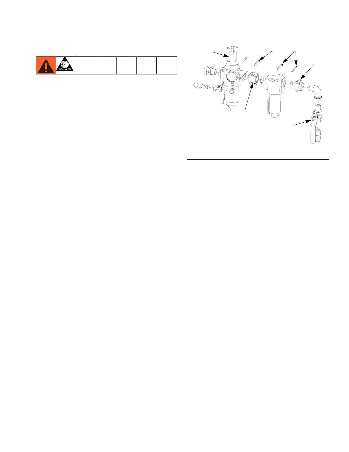
Adding a Lubricator (Accessory)
To add an accessory air line lubricator to the kit, you
must order Part No. 244841 Lubricator Accessory Kit.
1. Remove filter/regulator from mount bracket.
2. Remove the pin (B) from the outlet of the filter/regulator. F
3. Remove regulator cover.
4. Slide the threaded end insert off (13)with outlet fittings still attached.
5. Install the modular connector (2a) (with o-rings and
grease provided) between the filter/regulator and
the lubricator (L).
6. Install the threaded end insert (13) onto the outlet of
the lubricator (L) with o-ring and grease.
7. Install the three retaining pins (B).
NOTE: On light weight cart units only, replace the
3/4” npt pipe extension and the 3/4” npt f x f elbow
with the 3/4” npt f x m elbow supplied with kit
244841, refer to instructions (form 406512) included
with kit.
IG. 2.
1
2a
FIG. 2
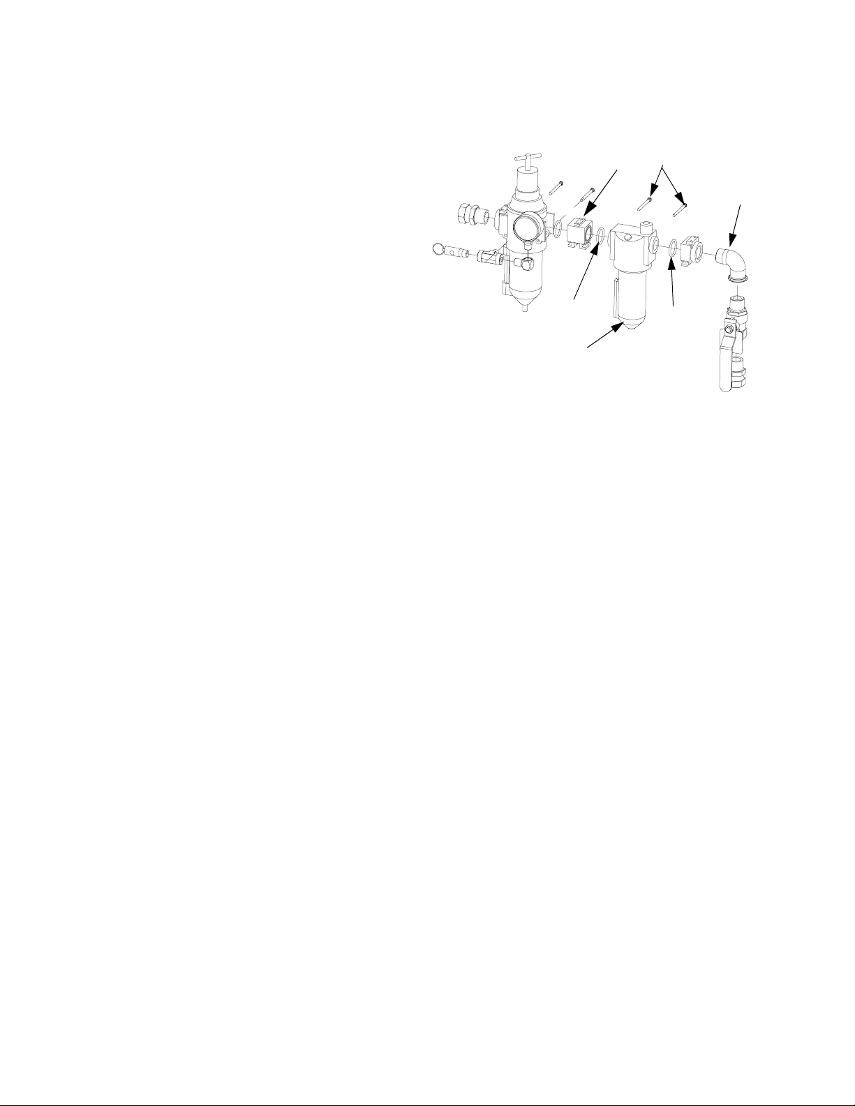
The lubricator meters oil into the moving air stream to
automatically lubricate air-operated motors. A manual
adjustment in the housing (F), Fig. 2, sets the oil drip
rate into the air stream, which can be monitored through
a sight glass. One to two drops of oil per minute is common. Use an oil rated at 50 to 200 SUS (ISO grade 7 to
46) at 100°F (38°C), such as Graco motor oil, Part No.
202659.
B
B
13
4
r_24e025_3A0293_4a
Refill Lubricator
1. Unscrew the fill plug (L, FIG. 2) and pour in the oil.
The lubricator’s capacity is 7 oz. (0.2 liter).
2. Check the oil level with the side sight glass. The
lubricator can be refilled with the system pressurized. However, always relieve the system pres-
sure before removing the bowl for any reason.
3A0293C 3
Page 4

Operation
Operation
Pressure Relief Procedure
1. Lock the gun trigger safety.
2. Close all bleed-type master air valves, including the
bleed-type master air valve (3), supplied in your system. F
IG. 2.
3. Turn the regulator T-handle all the way counterclockwise if you are removing the air filter/regulator (1)
bowl, or servicing the air filter/regulator.
4. Open any fluid shutoff valves.
5. Unlock the gun trigger safety.
6. Hold a metal part of the gun firmly to the side of a
grounded metal pail, and trigger the gun to relieve
pressure.
7. Lock the gun trigger safety.
8. Open any fluid drain valves (required in your system), having a container ready to catch the drainage.
Adjusting the Air Regulator
Use the bleed-type master air valve (3) to relieve air
trapped between it and the pump when the valve is
closed. This helps reduce the risk of serious injury,
including fluid injection and splashing of fluid in the
eyes or on the skin, and injury from moving parts if
you are adjusting or repairing the pump.
1. To increase the regulated air pressure, turn the
T-handle clockwise.
2. To decrease the regulated air pressure, turn the
T-handle counterclockwise.
3. To lock the regulator setting, tighten the jam nut.
4. Slowly open the air filter/regulator (1), F
the filter/regulator to control pump speed and fluid
pressure. Always use the lowest air pressure necessary to get the desired results. Higher pressures
cause premature tip and pump wear.
IG. 2. Use
9. Leave the drain valve(s) open until you are ready to
spray again.
If you suspect that the spray tip or hose is completely
clogged, or that pressure has not been fully relieved
after following the steps above, very slowly loosen the
tip guard retaining nut or hose end coupling and relieve
pressure gradually, then loosen completely. Now clear
the tip or hose.
4 3A0293C
Page 5

Repair
Repair
Air Regulator
Repair Kits are available. Refer to page 6.
Every day, drain contaminants from the bowl before
reaching the baffle level by opening the drain (D) at the
bottom of the bowl (B). See F
Clean the air filter regularly to maximize filtering efficiency and to avoid excessive pressure drop. Fully
relieve pressure to remove the bowl (B).
Clean the filter element and bowl using detergent and
water or denatured alcohol. Use compressed air to blow
out the filter body. Blow the filter element out from the
inside.
Service the regulator, if the regulator fails to operate,
operates roughly, or vibrates. Inspect all parts for wear
or damage. Replace damaged parts. Refer to page 7.
Lubricate the bearing area, all o-rings, adjusting screw
threads, and spring ends with no. 2 lithium-base grease.
See. F
IG. 3. Reassemble the regulator.
IG. 3.
Lubricator Service (Accessory)
An accessory Lubricator Kit is available. Order Part No.
244841. Repair Kits are available (refer to page 7) for an
accessory lubricator.
Clean the lubricator regularly to maximize efficiency.
Fully relieve pressure and remove the lubricator from
the air line.
Disassemble the lubricator.
Clean the parts with detergent and water or denatured
alcohol. Wipe dry with a clean, soft cloth.
Use compressed air to blow dirt and contaminants out of
the lubricator body. Inspect all parts for wear or damage.
Replace damaged parts.
Clean the sight glass (S) thoroughly. See Fig. 4. Do not
leave solvent residue in the sight glass as it may attack
or weaken the glass. If the sight glass appears damaged, replace it immediately.
Reassemble the lubricator.
3A0293C 5
Page 6

Repair Kits
Repair Kits
116521 Air Filter/Regulator C11034 Lubricator
1
Lubricate with no. 2
1
1
lithium-base grease.
Regulator Repair
Kit 116634
Bowl
Repair Kit
116672
Sight Dome Repair
Kit 116670
1
1
B
D
FIG. 3: 116521 Repair Kits
Bowl Replacement
Kit 116672
40 Micron Filter
Element Kit 116635
TI1251A
TI1252A
FIG. 4: C11034 Repair Kits
6 3A0293C
Page 7

Parts
24E025 Light Duty Air Controls
Parts
Ref.
No. Part No. Description Qty.
1 116521 REGULATOR, filter, air 1
2 160032 FITTING, nipple 1
3 113218 VALVE, ball, vented, 3/4 1
4 122327 ELBOW, street, pipe, 90° 1
5 157785 FITTING, swivel 2
6 108638 FITTING, pipe, tee 1
7 100840 FITTING, elbow, street 1
8 100960 GAUGE, press air 1
9* VALVE, safety 1
24E013 Heavy Duty Air Controls
Ref.
No. Part No. Description Qty.
1 116521 REGULATOR, filter, air 1
3 113218 VALVE, ball, vented, 3/4 1
5 157785 FITTING, swivel 1
6 108638 FITTING, pipe, tee 1
7 100840 FITTING, elbow, street 1
8 100960 GAUGE, press air 1
9* VALVE, safety 1
10 194545 CONNECTOR, bulkhead 1
11 160327 FITTING, union adapter, 90° 1
9*
9*
1
5
8
6
7
1
5
8
2
3
5
4
r_24e025_3a0293a_8
10
3
11
6
7
* Not included with air controls. Replace with appropriate part number from table below according to pump ratio.
Pump Ratio Part No. Description Pressure Relief
X90 116643 Safety Relief Valve 90 psi (0.6 MPa, 6.2 bar)
X25-X80 113498 Safety Relief Valve 110 psi (0.7 MPa, 7.6 bar)
3A0293C 7
r_24e025_3a0293a_9
Page 8
Parts
244841 Lubricator Conversion Kit
Ref.
No. Part No. Description Qty.
1 C11034 LUBRICATOR, air 1
2 116522 AIR CONTROL, conversion kit
(includes 2a-2c)
2a ADAPTER 1
2b PINS, retaining 2
2c O-RING 2
4 100549 ELBOW, street, 90°, 3/4 npt (m x f) 1
2a
2b
4
1
2c
2c
1
r_24e025_3A0293_4a
8 3A0293C
Page 9

Technical Data
Maximum air input pressure . . . . . . . . . . . . . . . . . . . . . . . 250 psi (1.7 MPa, 17.2 bar)
Air inlet size . . . . . . . . . . . . . . . . . . . . . . . . . . . . . . . . . . . 3/4 npsm(f)
Air outlet size . . . . . . . . . . . . . . . . . . . . . . . . . . . . . . . . . . 3/4 npt(f)
Gauge port size (air regulator) . . . . . . . . . . . . . . . . . . . . . 1/4 npt(f)
Air filter element . . . . . . . . . . . . . . . . . . . . . . . . . . . . . . . . 40 micron polypropylene screen
Maximum operating temperature 50°C (122°F)
MODEL 116521 AIR REGULATOR FLOW CURVE
80
(0.55, 5.5)
60
(0.41, 4.1)
40
(0.28, 2.8)
20
(0.14, 1.4)
Technical Data
OUTPUT PRESSURE (MPa, bar)
50
(1.120)
AIR FLOW AT INLET PRESSURE OF
100 PSI (0.7 MPa, BAR), 3/4 in. port,
100
(2.240)
and 40 micron element
150
(3.360)
200
(4.480)
(5.600)
250
3A0293C 9
Page 10

Graco Standard Warranty
Graco warrants all equipment referenced in this document which is manufactured by Graco and bearing its name to be free from defects in
material and workmanship on the date of sale to the original purchaser for use. With the exception of any special, extended, or limited warranty
published by Graco, Graco will, for a period of twelve months from the date of sale, repair or replace any part of the equipment determined by
Graco to be defective. This warranty applies only when the equipment is installed, operated and maintained in accordance with Graco’s written
recommendations.
This warranty does not cover, and Graco shall not be liable for general wear and tear, or any malfunction, damage or wear caused by faulty
installation, misapplication, abrasion, corrosion, inadequate or improper maintenance, negligence, accident, tampering, or substitution of
non-Graco component parts. Nor shall Graco be liable for malfunction, damage or wear caused by the incompatibility of Graco equipment with
structures, accessories, equipment or materials not supplied by Graco, or the improper design, manufacture, installation, operation or
maintenance of structures, accessories, equipment or materials not supplied by Graco.
This warranty is conditioned upon the prepaid return of the equipment claimed to be defective to an authorized Graco distributor for verification of
the claimed defect. If the claimed defect is verified, Graco will repair or replace free of charge any defective parts. The equipment will be returned
to the original purchaser transportation prepaid. If inspection of the equipment does not disclose any defect in material or workmanship, repairs will
be made at a reasonable charge, which charges may include the costs of parts, labor, and transportation.
THIS WARRANTY IS EXCLUSIVE, AND IS IN LIEU OF ANY OTHER WARRANTIES, EXPRESS OR IMPLIED, INCLUDING BUT NOT LIMITED
TO WARRANTY OF MERCHANTABILITY OR WARRANTY OF FITNESS FOR A PARTICULAR PURPOSE.
Graco’s sole obligation and buyer’s sole remedy for any breach of warranty shall be as set forth above. The buyer agrees that no other remedy
(including, but not limited to, incidental or consequential damages for lost profits, lost sales, injury to person or property, or any other incidental or
consequential loss) shall be available. Any action for breach of warranty must be brought within two (2) years of the date of sale.
GRACO MAKES NO WARRANTY, AND DISCLAIMS ALL IMPLIED WARRANTIES OF MERCHANTABILITY AND FITNESS FOR A
PARTICULAR PURPOSE, IN CONNECTION WITH ACCESSORIES, EQUIPMENT, MATERIALS OR COMPONENTS SOLD BUT NOT
MANUFACTURED BY GRACO. These items sold, but not manufactured by Graco (such as electric motors, switches, hose, etc.), are subject to
the warranty, if any, of their manufacturer. Graco will provide purchaser with reasonable assistance in making any claim for breach of these
warranties.
In no event will Graco be liable for indirect, incidental, special or consequential damages resulting from Graco supplying equipment hereunder, or
the furnishing, performance, or use of any products or other goods sold hereto, whether due to a breach of contract, breach of warranty, the
negligence of Graco, or otherwise.
FOR GRACO CANADA CUSTOMERS
The Parties acknowledge that they have required that the present document, as well as all documents, notices and legal proceedings entered into,
given or instituted pursuant hereto or relating directly or indirectly hereto, be drawn up in English. Les parties reconnaissent avoir convenu que la
rédaction du présente document sera en Anglais, ainsi que tous documents, avis et procédures judiciaires exécutés, donnés ou intentés, à la suite
de ou en rapport, directement ou indirectement, avec les procédures concernées.
Graco Information
For the latest information about Graco products, visit www.graco.com.
TO PLACE AN ORDER, contact your Graco distributor or call to identify the nearest distributor.
Phone: 612-623-6921 or Toll Free: 1-800-328-0211 Fax: 612-378-3505
All written and visual data contained in this document reflects the latest product information available at the time of publication.
Graco reserves the right to make changes at any time without notice.
Original instructions. This manual contains English. MM 3A0293
Graco Headquarters: Minneapolis
International Offices: Belgium, China, Japan, Korea
GRACO INC. P.O. BOX 1441 MINNEAPOLIS, MN 55440-1441
Copyright 2010, Graco Inc. is registered to ISO 9001
www.graco.com
Revised 03/2011
 Loading...