

Page 1
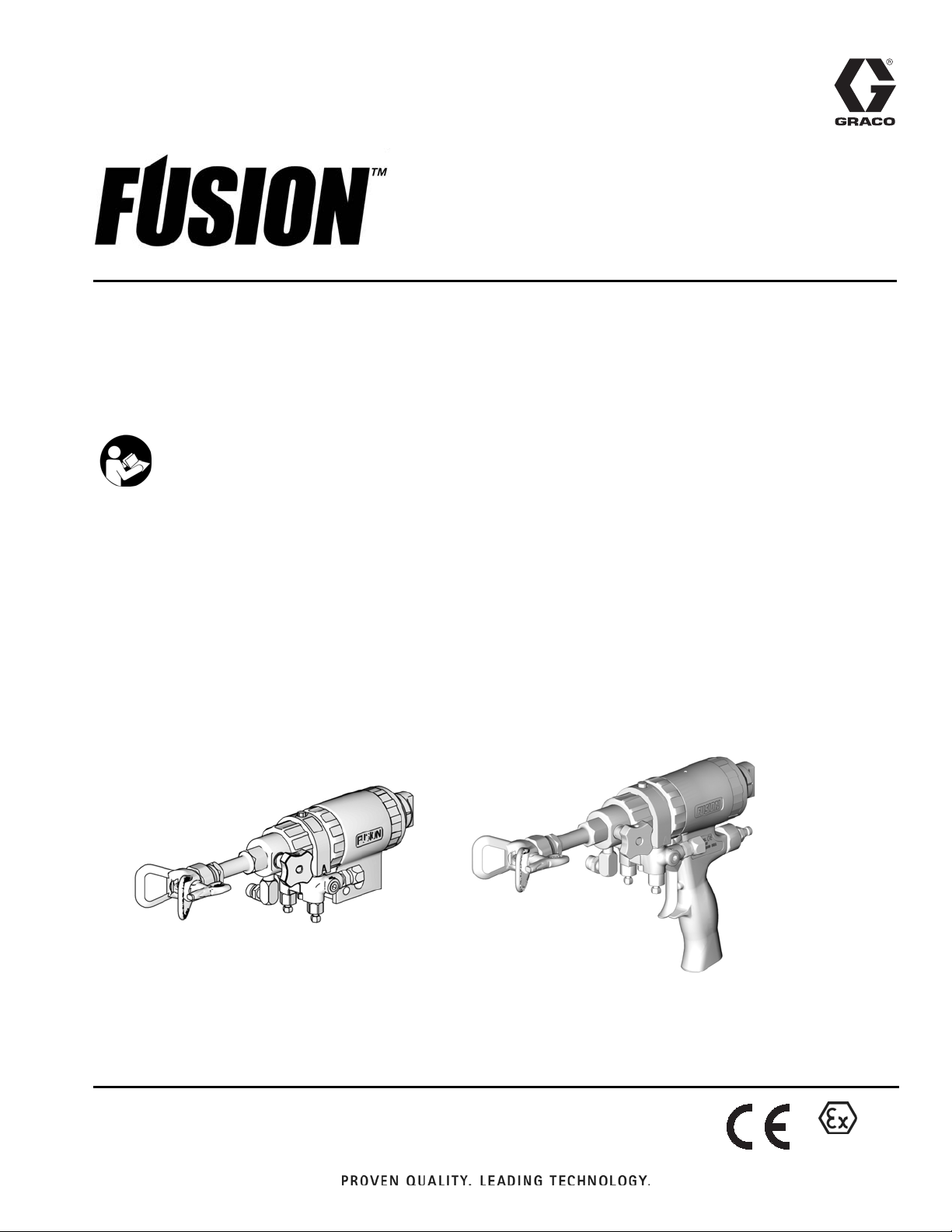
Instructions-Parts
310648P
Solvent Purge Plural Component Gun
For use with non-flammable foam and polyurea. For professional use
only. Not for use in explosive atmospheres.
Important Safety Instructions
Read all warnings and instructions in thismanual.
Save these instructions.
EN
248597, Series A
Solvent Purge Manual Spray Gun
248647, Series B
Machine Mount Spray Valve with Manual Solvent Purge
248603, Series A
Standard Mechanical Purge ConversionKit
3500 psi (24.2 MPa, 242 bar) Maximum Fluid Working Pressure
80-130 psi (0.55-0.9 MPa, 5.5-9.1 bar) Air Inlet Pressure Range
200°F (94°C) Maximum FluidTemperature
3500 psi (24.2 MPa, 242 bar) Maximum Solvent Working Pressure
TI5006c
TI4965b
II 2 G
Page 2

Contents
Manual Conventions ........................3
OverallView ...............................6
Important Isocyanate (ISO) Information ........7
Material Self-ignition ......................8
Keep Components A and B Separate .........8
Moisture Sensitivity of Isocyanates ...........8
Foam Resins with 245 fa Blowing Agents ......9
Changing Materials .......................9
Grounding ................................9
Piston Safety Lock ........................10
Loss of Air Pressure .......................10
Conversion Kit 248603 .....................11
Mounting an Automatic Gun .................12
Mounting to a rod .......................12
Mounting to a stationary support robotic arm . . 12
Connecting Airline and Accessories .........12
Setup ....................................13
Hand Drilling of Mix Modules ................15
To balance pressure and flow at the mix gun . . 15
CheckValve Filter Option .................15
Tools required ..........................15
Operation ................................17
Spraying ..............................17
Flushing with Solvent Purge Assembly .......17
Shutdown ................................18
Daily Shutdown .........................18
Shutdown for More than a Day .............18
Pressure Relief Procedure ..................19
Optional Configurations ....................21
Optional Fluid Manifold Position ............21
Optional Hose Position ...................22
Maintenance ..............................23
Supplied Tool Kit ........................23
Keep Gun Clean ........................23
As Needed ............................23
Daily .................................23
Weekly to Monthly .......................23
Flush Gun .............................24
Clean Outside of Gun ....................24
Clean Air Cap ..........................24
Clean SprayTip .........................24
Clean Muffler ...........................24
Clean Fluid Manifold .....................24
Clean Mixer ............................24
Clean Slip-Fit Polycarballoy Mix Module ......25
Troubleshooting ...........................26
Theory of Operation ......................28
Cutaway View ..........................29
Repair ...................................30
Tools Required ..........................30
Lubrication .............................30
Disassemble Front End ...................30
Reassemble Front End ...................
Slip-Fit Polycarballoy Mix Module ...........34
Rear Rod Seal ..........................36
Adjust Rear Rod Seal ....................37
CheckValves ...........................38
Piston and Purge Rod ....................39
Piston Safety Lock .......................41
AirValve...............................41
Solvent Purge Assembly ..................42
Static Mixer Assembly ....................43
Parts ....................................45
248597 and 248647 Solvent Purge Plural
Component Spray Guns, and 248603
Conversion Kit .......................45
248597 Solvent Purge Manual Spray Gun ....46
248597 Solvent Purge Manual Spray Gun ....47
248647 Machine Mount SprayValve
with Manual Solvent Purge .............48
248647 Machine Mount SprayValve
with Manual Solvent Purge .............49
Slip-Fit Polycarballoy Mix Module Kits ........50
GunandPalmGrips .....................50
Drill Bit Kits ............................51
Gun Repair Kits ...........................52
CheckValve Filter Screen Kits (10 per kit) ....52
DrillBitKit .............................52
Model 248647 Mounting Dimensions ..........53
Technical Data ............................54
Graco Standard Warranty ...................56
Graco Information .........................56
32
2 310648P
Page 3

Manual Conventions
Warning Caution
Manual Conventions
WARNING
A warning alerts you to possible serious injury or
death if you do not follow instructions.
Symbols, such as fluid injection (shown), alert you to a
specific hazard and direct you to read the indicated
hazard warnings on pages 4-5.
CAUTION
A caution alerts you to possible equipment damage or
destruction if you do not follow instructions.
Note
A note indicates additional helpful information.
Component Labels
Depending on chemistry and material manufacturer,
individual fluid components havedifferent labels. Sometimes (A) is the ISO or hardener. Sometimes (A) is the
RESIN or filled side. For the purpose of these valves
and this manual, (A) refers to the ISO, or hardener,
which will most often be the minor volume side. (B)
refers to the RESIN side, which normally contains the
fillers and is the major volume side.
310648P 3
Page 4
Warning
WARNING
PERSONAL PROTECTIVE EQUIPMENT
Always wear appropriate personal protective equipment and cover all skin when spraying, servicing
equipment, or when in the work area. Protective equipment helps prevent serious injury, including
long-term exposure; inhalation of toxic fumes, mists or vapors; allergic reaction; burns; eye injury and
hearing loss. This protective equipment includes but is not limited to:
• A properly fitting respirator,which may include a supplied-air respirator, chemically impermeable
gloves, protective clothing and foot coverings as recommended by the fluid manufacturer and local
regulatory authority.
• Protective eyewear and hearing protection.
TOXIC FLUID OR FUMES HAZARD
Toxic fluids or fumes can cause serious injury or death if splashed in the eyes or on skin, inhaled or
swallowed.
• Read Safety Data Sheet (SDS) for handling instructions and to know the specific hazards of the fluids you are using, including the effects of long-term exposure.
• When spraying, servicing equipment, or when in the work area, always keep work area well ventilated and always wear appropriate personal protective equipment. See PersonalProtective Equip-
ment warnings in this manual.
• Store hazardous fluid in approved containers, and dispose of it according to applicable guidelines.
FIRE AND EXPLOSION HAZARD
Flammable fumes, such as solvent and paint fumes, in work area can ignite or explode.To help prevent
fire and explosion:
• Use equipment only in well ventilated area.
• Eliminate all ignition sources, such as pilot lights, cigarettes, portable electric lamps, and plastic drop
cloths (potential static arc).
• Do not plug or unplug power cords or turn lights on or off when flammable fumes are present.
• Keep the work area free of debris, including solvent, rags, and gasoline.
• Ground equipment and conductive objects. See Grounding, page 9.
• Hold gun firmly to side of grounded pail when triggering into pail.
• Use only grounded hoses.
• If there is static sparking or you feel a shock, stop operation immediately. Do not use equipment
until you identify and correct the problem.
• Keep a fire extinguisher in the work area.
4 310648P
Page 5
Warning
WARNING
SKIN INJECTION HAZARD
High-pressure fluid from gun, hose leaks,or ruptured components will pierce skin. This maylook like just
a cut, but it is a serious injury that can result in amputation. Get immediate surgical treatment.
• Do not point the gun at anyone or at any part of the body.
• Do not put your hand over the spray tip.
• Do not stop or deflect leaks with your hand, body, glove, or rag.
• Do not “blow back” fluid; this is not an air spraysystem.
• Follow Pressure Relief Procedure, page 19, when you stop spraying and before cleaning, checking, or servicing equipment.
• Use lowest possible pressure when flushing, priming, or troubleshooting.
• Engage piston safety lock when not spraying.
• Tighten all fluid connections before operating the equipment.
• Check hoses, tubes, and couplings daily. Replace worn or damaged parts immediately. High pressure hose cannot be recoupled; replace the entire hose.
BURN HAZARD
Equipment surfaces and fluid that’s heated can become very hot during operation. To avoid severe
burns, do not touch hot fluid or equipment. Wait until equipment/fluid has cooled completely.
EQUIPMENT MISUSE HAZARD
Misuse can cause serious injury or death.
• For professional use only.
• Use equipment only for its intended purpose. Call your Graco distributor for information.
• Read manuals, warnings, tags, and labels before operating equipment. Follow instructions.
• Check equipment daily. Repair or replace worn or damaged parts immediately.
• Do not alter or modify equipment. Use only Graco parts and accessories.
• Do not exceed the maximum working pressure or temperature rating of the lowest rated system
component. SeeTechnical Data in all equipment manuals.
• Use fluids and solvents that are compatible with equipment wetted parts. See Technical Data in all
equipment manuals. Read fluid and solvent manufacturer’s warnings.
• Route hoses and cables away from traffic areas, sharp edges, moving parts, and hot surfaces.
• Do not kink or overbend hoses or use hoses to pull equipment.
• Comply with all applicable safety regulations.
PRESSURIZED ALUMINUM PARTS HAZARD
Do not use 1,1,1-trichloroethane, methylene chloride, other halogenated hydrocarbon solvents or fluids
containing such solvents in pressurized aluminum equipment. Such use can cause serious chemical
reaction and equipment rupture, and result in death, serious injury, and property damage.
310648P 5
Page 6
Overall View
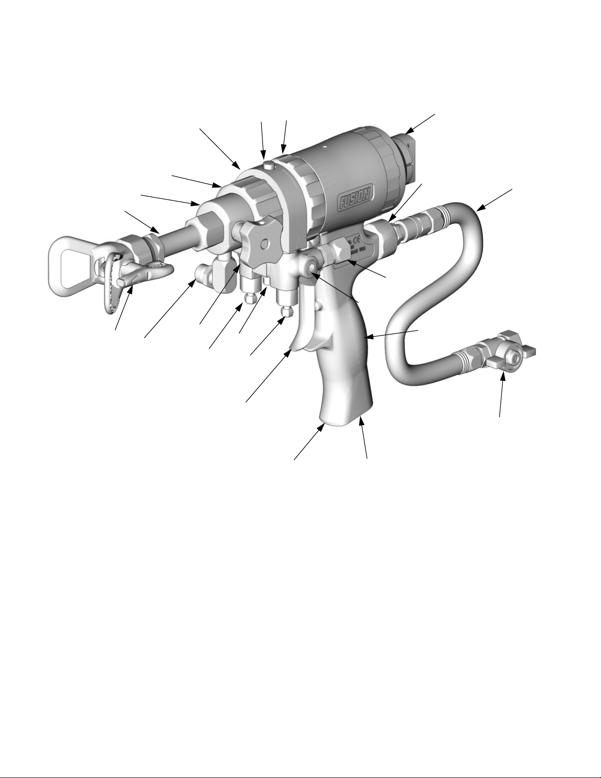
OverallView
K
P
L
F
C
M
D
T
W
R
N
X
Y
V
G
B
A
H
Key:
A A Side Fluid Valve (ISO)
B B Side Fluid Valve (RESIN)
C Air Cap
D Air Line Quick Coupler
E Muffler
F Fluid Housing
G Gun Fluid Manifold
H Handle
J Optional Air Inlet
K Cleanoff Air Valve
L Piston Safety Lock
M SolventPurge Assembly
S
U
J
N Optional Fluid Inlets (A Side Shown)
P Lock Ring
R Fluid Inlet Swivels (A Side Shown)
S Trigger
T Gun Air Whip Hose
U Air Valve
V Solvent Purge Valve
W Static Mixer
X RAC tip
Y Solvent Fluid Inlet
E
TI4966b
6 310648P
Page 7

Important Isocyanate (ISO) Information
Important Isocyanate (ISO) Information
Isocyanates (ISO) are catalysts used in two component materials.
Isocyanate Conditions
Spraying or dispensing fluids that contain isocyanates creates potentially harmful mists, vapors, and atomized particulates.
• Read and understand the fluid manufacturer’s warnings and Safety Data Sheet (SDS) to know specific
hazards and precautions related to isocyanates.
• Use of isocyanates involvespotentially hazardous procedures. Do not spraywith this equipment unless
you are trained, qualified, and have read and understood the information in this manual and in the fluid
manufacturer’s application instructions and SDS.
• Use of incorrectly maintained or mis-adjusted equipment may result in improperly cured material.which
could cause off gassing and offensive odors. Equipment must be carefully maintained and adjusted
according to instructions in the manual.
• To prevent inhalation of isocyanate mists, vapors and atomized particulates, everyone in the work area
mustwear appropriaterespiratory protection.Alwayswear aproperly fittingrespirator,which mayinclude
a supplied-air respirator.Ventilatethe workarea accordingto instructions inthe fluid manufacturer’sSDS.
• Avoid all skin contact with isocyanates. Everyone in the work area must wear chemically impermeable
gloves, protective clothing and foot coverings as recommended by the fluid manufacturer and local regulatory authority. Follow all fluid manufacturer recommendations, including those regarding handling of
contaminated clothing. After spraying, wash hands and face before eating or drinking.
• Hazard from exposureto isocyanates continues after spraying.Anyonewithout appropriate personal protective equipment must stay out of the work area during application and after application for the time
period specified by the fluid manufacturer. Generally this time period is at least 24 hours.
• Warn others who may enter work area of hazard from exposure to isocyanates. Follow the recommendations of the fluid manufacturer and local regulatory authority. Posting a placard such as the following
outside the work area is recommended:
TOXIC FUMES
HAZARD
DO NOT ENTER DURING
SPRAY FOAM APPLICATION
OR FOR ___ HOURS AFTER
APPLICATION IS COMPLETE
DO NOT ENTER UNTIL:
DATE:
TIME:
310648P 7
____________
____________
Page 8
Important Isocyanate (ISO) Information
For all applications except spray foam
Spraying or dispensing fluids that contain isocyanates
creates potentially harmful mists, vapors,and atomized
particulates.
• Read and understand the fluid manufacturer’s
warnings and Safety Data Sheet (SDS) to know
specific hazards and precautions related to isocyanates.
• Use of isocyanates involves potentially hazardous
procedures. Do not spray with this equipment
unless you are trained, qualified, and have read
and understood the information in this manual and
in the fluid manufacturer’s application instructions
and SDS.
• Use of incorrectly maintained or mis-adjusted
equipment may result in improperly cured material.
Equipment must be carefully maintained and
adjusted according to instructions in the manual.
• To prevent inhalation of isocyanate mists, vapors,
and atomized particulates, everyone in the work
area must wear appropriate respiratory protection.
Alwayswear a properly fitting respirator, which may
include a supplied-air respirator. Ventilate the work
area according to instructions in the fluid manufacturer’s SDS.
Avoid all skin contact with isocyanates. Everyone in
the work area must wear chemically impermeable
gloves, protective clothing and foot coverings as
recommended by the fluid manufacturer and local
regulatory authority. Follow all fluid manufacturer
recommendations,including those regardinghandling
of contaminated clothing. After spraying, wash hands
and face before eating or drinking.
Material Self-ignition
Keep Components A and B Separate
Cross-contamination can result incured material influid
lines which could cause serious injury or damage
equipment. To prevent cross-contamination:
• Never interchange component A and component B
wetted parts.
• Neveruse solventon oneside if ithas been contaminated from the other side.
Moisture Sensitivity of Isocyanates
Exposure to moisture (such as humidity) will cause ISO
to partially cure, forming small, hard, abrasive crystal
that becomesuspended in the fluid. Eventually a film will
form on the surface and the ISO will begin to gel,
increasing in viscosity.
NOTICE
Partially cured ISO will reduce performance and the
life of all wetted parts.
• Always use a sealed container with a desiccant
dryer in the vent,or a nitrogen atmosphere. Never
store ISO in an open container.
• Keep the ISO pump wet cup or reservoir (if
installed) filled with appropriate lubricant. The
lubricant creates a barrier between the ISO and
the atmosphere.
• Use only moisture-proof hoses compatible with
ISO.
• Never use reclaimed solvents, which may contain
moisture. Always keep solvent containers closed
when not in use.
• Always lubricate threaded parts with an appropriate lubricant when reassembling.
Some materials may become self-igniting if applied
too thick.Read material manufacturer’s warnings and
Safety Data Sheet (SDS).
8 310648P
NOTE:The amount of film formation and rate of crystallization varies depending on the blend of ISO, the
humidity, and the temperature.
Page 9

Grounding
Foam Resins with 245 fa Blowing Agents
Some foam blowing agents will froth at temperatures
above 90°F (33°C) when not under pressure, especially
if agitated. To reduce frothing, minimize preheating in a
circulation system.
Changing Materials
NOTICE
Changing the material types used in your equipment
requires special attention to avoid equipment damage
and downtime.
• When changing materials, flush the equipment
multiple times to ensure it is thoroughly clean.
• Always clean the fluid inlet strainers after flushing.
• Check with your material manufacturer for chemical compatibility.
• When changing between epoxies and urethanes
or polyureas, disassemble and clean all fluid components and change hoses. Epoxies often have
amines on the B (hardener) side. Polyureas often
have amines on the B (resin) side.
Grounding
WARNING
Read warnings, page 4.
Check your local electrical code and proportioner manual for detailed grounding instructions.
Solvent line must be Graco approved grounded hose.
Primary ground is through the grounded solvent supply
hose.
Ensure that solvent supply pump is properly grounded.
Ensure continuity from the spray tip to grounded solvent
hose when using static mixers and tips other than supplied with gun.
310648P 9
Page 10
Piston Safety Lock
Piston Safety Lock
Engage piston safety lock whenever you stop spraying, to avoid accidental triggering.
WARNING
Read warnings, page 5.
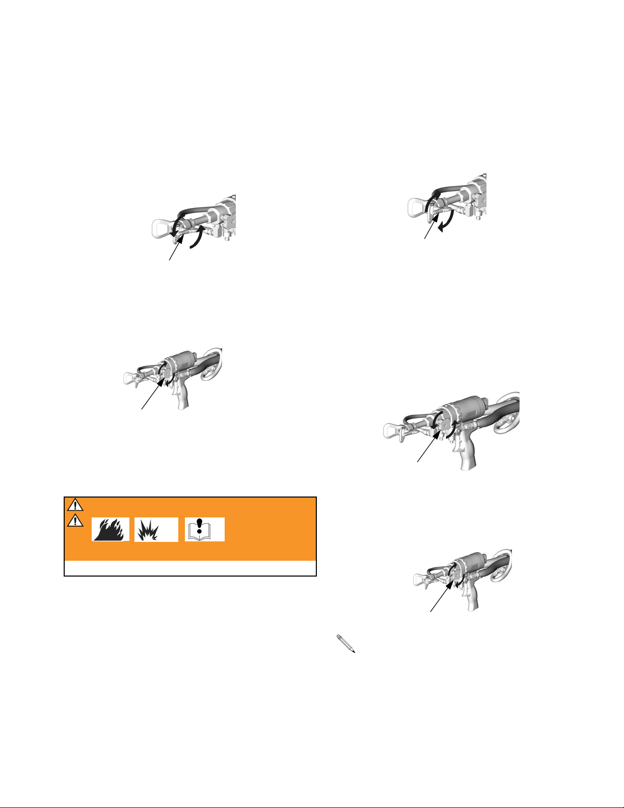
To engage piston safety lock: push knob in and turn
clockwise.When engaged, piston safety lock allows
some purge rod movement but shuts off fluid flow and
gun cannot spray.
TI3850a
To disengage piston safety lock: push knob in and
turn counterclockwise until it pops out.
Loss of Air Pressure
In event of loss of air pressure while gun is triggered,
gun will continue to spray. To shut off gun, do one of the
following:
• Push hard or hit end of safety lock, to engage piston
safety lock.
TI5003a
• Close fluid valves A and B.
TI4967b
TI3849a
10 310648P
Page 11
Conversion Kit 248603
A Standard Mechanical Purge Gun can be converted
into a Solvent Purge Gun with this kit.
1. Relieve pressure. See manual 309856.
2. Flush Gun, page 24.
Conversion Kit 248603
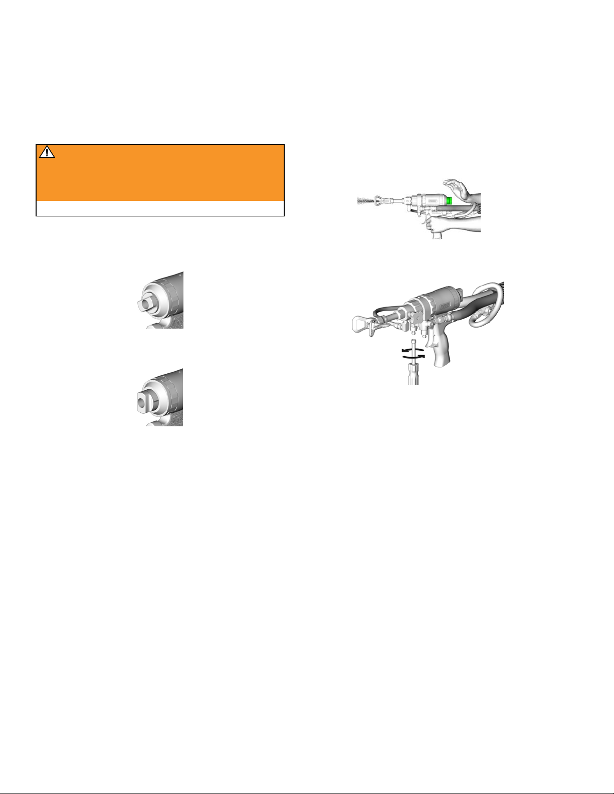
7. Liberallylubricate piston o-rings.Install spacer (61)
onto piston assembly. Reinstall piston. Shaft is
keyed for proper assembly. Push firmly to seat piston. Rotate piston/purge rod assembly clockwise
with nut driver until piston is fully seated.
3. Disassemble front end of gun. Refer to manual
309856.
4. Disassemble the piston and purge rod assembly
from the gun, see Piston and Purge Rod in manual 309856.
5. Remove purge rod (31) from assembly and place
spacer (62) onto purge rod.
31
62
61
61
TI4988a
Spacer (61) is optional. For more forward travelof
piston, remove spacer.
8. Install piston safety lock assembly until bottomed
out.
TI3847a
TI4989a
9. Reassemble the fluid housing onto the front end of
the gun. See Reassemble Front End, page 32,
6. Reassemble purge rod and piston assembly until
positive stop on purge rod spacer (62).
310648P 11
steps 1 through 6.
Page 12
Mounting an Automatic Gun
Mounting an Automatic Gun
Mounting to a rod Mounting to a stationary
support robotic arm
1. To mount the gun on a 1/2 in. diameter rod, insert
the bar (A) through the hole in the gun body as
shown.
ti5007b
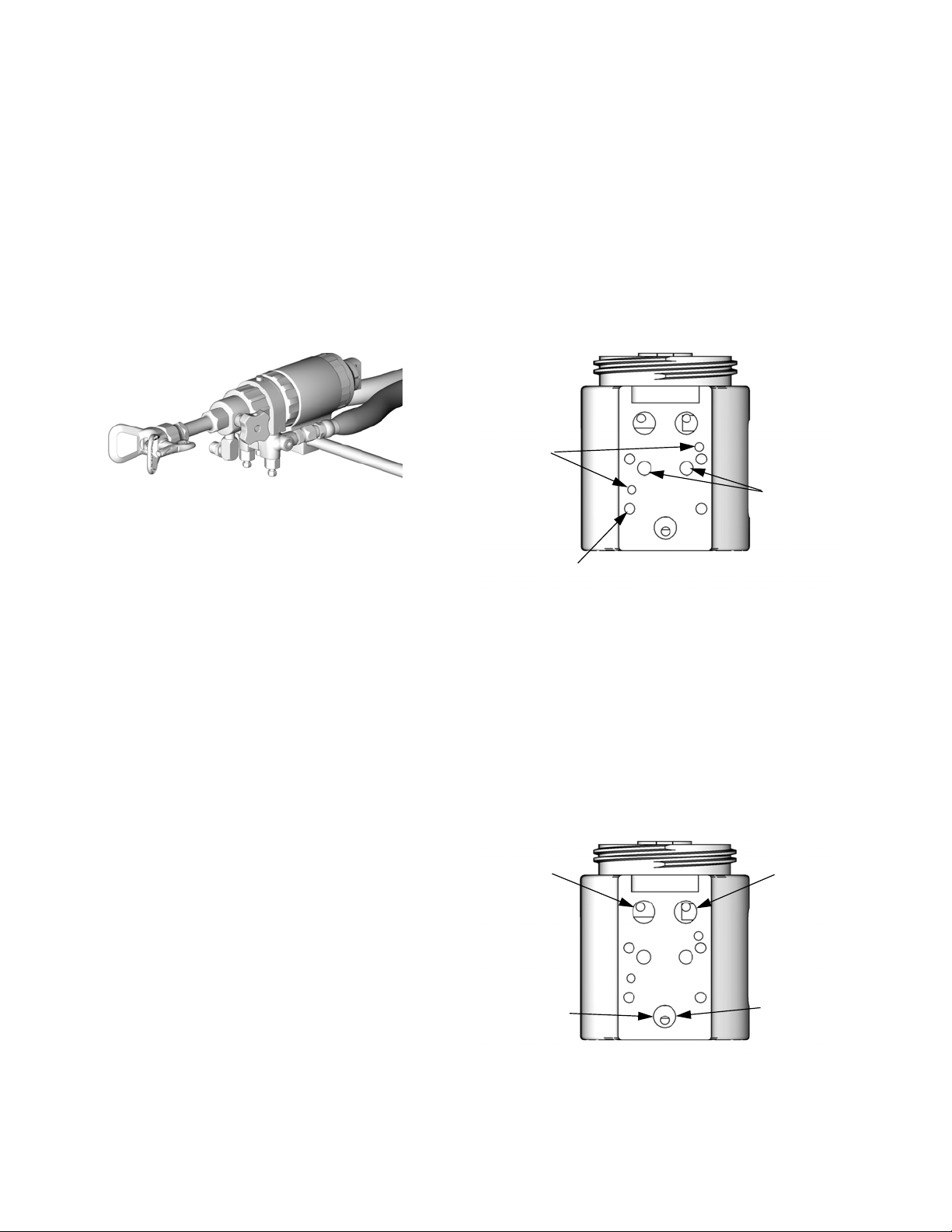
To mount gun to stationary support or robot arm, see
mounting hole dimensions, page 53.
Two .128 in.
alignment
pin holes
Four M5 x 0.08 in. (6.3 mm) holes
2. Secure the gun to the bar by tightening 1/4 in. - 20
mounting screws.
Connecting Airline and Accessories
P
I - Activation
P - Purge/Clean-off
O - Deactivation
I
O
Two 1/4 20 unc
holes
ti4751b
1. On the gun air supply line, install an air pressure
regulator.
• A minimum of 80 psi (0.55 MPA, 5.5 bar) air
pressure must be supplied to the gun for proper
operation.
• A four-wayair valve, which exhausts cylinder air
in both directions, is required.
2. On the gun air supply line, install a bleed-type air
shutoff valve downstream of the gun air regulator.
12 310648P
3. On the main air line, install a bleed-type air shutoff
valve.
Clean off air
Three 1/8 npt
ports (air
inlet)
I
P
O
I - Activation
P - Purge/Clean-off
O - Deactivation
Gun
actuation
Gun
deactuation
ti4751b
Page 13

Setup
Setup
1. Read Hand Drilling of Mix Modules, page 15,
before performing setup procedure.
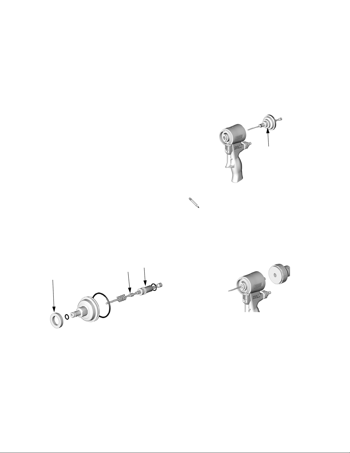
2. Assemble gaskets (40c), static mixer assembly
(40), o-ring (40d), adapter (41), and RAC tip and
guard (9, 63) assembly to fluid housing on front
end of gun.
40, 40d
41
9, 63
• Solvent purge knob (V) and inlet (Y) can be
rotated in any direction.
40c
VY
TI5033b
3. Close fluid valves A and B.
5. Engage piston safety lock (L), page 10.
L
TI3850a
6. Connect gun air whip hose (T) and air valve (U) to
main air hose. Attach fluid manifold (G) to gun.
T
G
To change position of fluid manifold or use
optional fluid inlets, see pages 21 and 22.
U
TI4968b
7. Connect air line to quick coupler (D). Turn on air.
Open air valve (U). Air valve (K) should be
screwed tight.There is no clean off air to adjust on
TI2411A
the solvent purge gun.
K
4. Connect A (ISO) and B (RESIN) fluid hoses to fluid
manifold (G).
B (RESIN)
G
U
D
J
A (ISO)
TI2417A
310648P 13
To use optional air inlet (J), see page 22.
TI4969b
Page 14

Setup
8. To adjust purge rod position, follow piston and
purge rod disassembly instruction on page 39.
9. Attach Gracoapproved groundedfluid supply hose
to solvent inlet (Y).
Make sure solvent purge valve (V) is closed before
pressurizing the solvent hose.
Y
To avoid getting mixed coating material in the solvent purge valve and line.
• Pressurize the solvent line before triggering the gun.
• Have an adequate solvent supply before
spraying.
• Keep air purged out of solvent hose.
• Install an accessory check valve at purge
valve inlet.
• Never trigger gun with solvent valve
open.
V
TI5004b
12. Disengage piston safety lock (L), page 10.
L
TI3849a
13. Turn RAC tip (X) to spray position.
X
TI5096b
14. Test spray onto cardboard. Adjust pressure,
temperature, or orifice size to get desired
results. If applying materials that are greater
than 1:1 ratio, follow the instructions for increasing orifice size, see Drilling of Mix Modules,
page 15.
10. Turn on proportioner.
TI3861a
11. Open B (RESIN) fluid valve. Then open A (ISO)
fluid valve.
15. Apply layer of lubricant over front of gun and
lock ring, or use gun cover to prevent overspray
buildup and ease disassembly.
16. Gun is ready to spray.
B
A
14 310648P
TI4970b
Page 15
Hand Drilling of Mix Modules
Hand Drilling of Mix Modules
To balance pressure and
flow at the mix gun
Graco only makes 1:1 ratio mix modules. When applying a material that is different than 1:1 it is necessary to
modify the mix module to allow more material through
the larger part side.
The actual size of the orifice required is dependent on
many factors such as material viscosity, shear, ratio tip
size, etc. For example, a 2:1 material by volume does
not necessarily require the diameter on the larger part
side to be doubled.
CheckValve Filter Option
See Check Valve Filter Screens, page 52. Gun is
shipped with 80 mesh filters on both the A and B check
valves. 40 mesh (quantity 2) and 60 mesh (quantity 2)
filters are included with the gun. For wider ratio materials it is advisable to decrease the filter size on the larger
part side to decrease pressure drop.
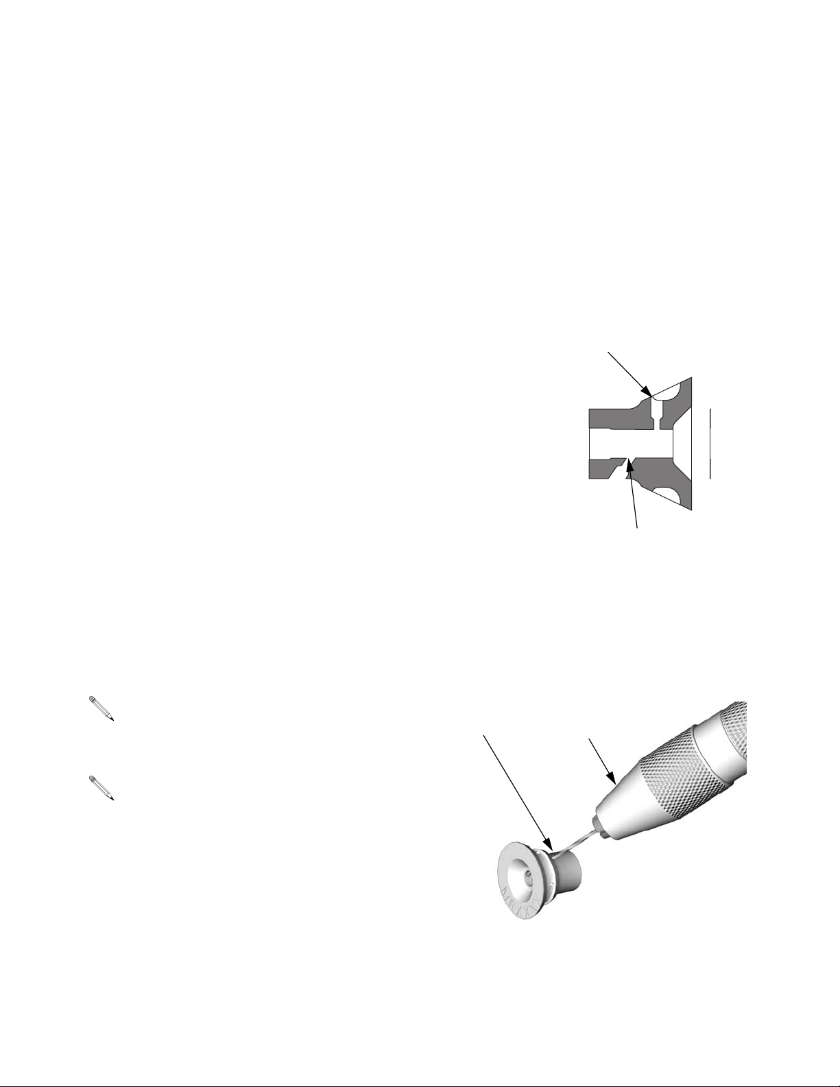
4. Locate the larger part side (typically the B [RES]
port at rear of Polycarballoy Mix Module).
Polycarballoy Mix Module cross section.
NOTE: View is not to scale.
A(ISO)
TI3876a
B (RES)
Mix Module
XF1313
Tools required
• Assorted Drill Bit Kit 119386
• Pin Vise 117661
Two XF1313 Polycarbolloy mix modules are
included with the gun. Additional mix modules are
available, see page 50.
Larger Modules XF3535, XF4747, XF5757 are
available but not included with gun.
1. Follow Pressure Relief Procedure, page 19.
2. Flush Gun, page 24.
3. Remove Polycarballoy Mix Module, see page 34.
5. Open up resin porting to raise ISO pressure. Start-
ing with the smallest drill bit size,drill into port. For
drill bit sizes, see Drill BitTable, page 16.
B (RES)
117661
Pin Vise
TI3862a
310648P 15
Page 16

Hand Drilling of Mix Modules
When drilling, be careful not to allow bit to come
in contact with ID of mix module.
The largest drill size that can be used on the
XF1313 mix module is #56. To get more flow,
order a larger mix module: XF3535, XF4747,
XF5757
6. Reassemble gun, page 34.
7. Check pressure gauges. A (ISO) and B (RES)
gauges should balance at the required pressure,
flow, and temperature operation points.
8. If ISO gauge still reads lower than the RESIN,
repeat steps 1 through 7. Use the next drill bit size
for drilling the B (RES) port on the mix module.
9. If you get the system pressure balanced but do not
have enough flow at the gun, drilling port A (ISO)
may be necessary. Drill port A (ISO) out to next
size. Repeat steps 1 through 8 to bring the pressure gauges back into balance.
Module Port Drill Bit Size
A
B
Drill BitTable
Drill Bit Sizes
# size Diameter (in.) Diameter (mm)
81 0.013 0.33
80 0.0135 0.34
79 0.0145 0.37
78 0.016 0.41
77 0.018 0.46
76 0.02 0.51
75 0.021 0.53
74 0.0225 0.57
73 0.024 0.61
72 0.025 0.64
71 0.026 0.66
70 0.028 0.71
69 0.0292 0.74
68 0.031 0.79
67 0.032 0.81
66 0.033 0.84
65 0.035 0.89
64 0.036 0.92
63 0.037 0.94
62 0.038 0.97
61 0.039 0.99
60 0.04 1.02
58 0.042 1.07
56 0.0465 1.18
A (ISO)
TI3863a
10. Repeat drilling until system pressures are bal-
anced.
11. After system pressures are balanced, record the
final drill bit sizes for each port in the chart
below. Use this information when it is time to
replace the Polycarballoy Mix Module.
16 310648P
Page 17
Operation
Operation
Spraying
1. To spray, turn RAC tip (X) to spray position.
X
2. Close solvent purge knob (V).
V
TI5004b
2. Turn RAC tip (X) to clean position.
TI5097b
X
TI5096b
3. Hold gun into a grounded metal pail, holding a
metal part of fluid manifold firmly to side of pail.
4. Open the solvent purge knob (V) to introduce sol-
vent to the static mixer assembly.
3. Trigger gun to spray.
WARNING
Read warnings page, 4.
Flushing with Solvent Purge Assembly
1. Detrigger the gun and engage safety lock.
V
TI5110b
5. When static mixer and tip are clean, close solvent
purge knob (V).
V
• For more thorough static mixer cleaning,
remove the spray tip.
• Minimize the amount of flushing time. Do not
atomize solvent.
TI5004b
310648P 17
Page 18

Shutdown
Shutdown
Daily Shutdown
1. Follow Pressure Relief Procedure, page 19.
2. Flush Gun, page 24.
Shutdown for More than a Day
1. Follow Pressure Relief Procedure, page 19.
2. Flush Gun, page 24.
18 310648P
Page 19

Pressure Relief Procedure
Pressure Relief Procedure
WARNING
Read warnings, page 5. Relieve pressure before
cleaning or repairing gun.
1. Engage piston safety lock (L), page 10.
L
TI3850a
Air supply is required for gun actuation. Do not
disconnect gun air supply until fluid pressure is
relieved.
2. Close fluid valves A and B. Leave air valve (U)
open.
4. Turn RAC tip (X) to clean position.
X
TI5097b
5. Trigger gun onto cardboard or into waste container
to relieve pressure.
TI5009a
B
U
A
TI5005b
3. Disengage piston safety lock (L), page 10.
L
TI3849a
310648P 19
Page 20

Pressure Relief Procedure
6. Engage piston safety lock (L), page 10.
L
TI3850a
WARNING
If fluid in the hose and proportioner is still under pressure, follow the Pressure Relief Procedure in the proportioner manual.
To relieve pressure in the hose after the gun is
removed, place the fluid manifold over containers, facing away from you. Very carefully open the fluid
valves. Under high pressure, fluid will spray sideways
from the fluid ports.
TI2484A
7. Flush static mixer and tip, see Flushing with Sol-
vent Purge Assembly, page 17.
8. Shut off air to solvent supply. Open solvent purge
knob (V) and relieve pressure in the solvent line.
V
20 310648P
TI5110b
Page 21

Optional Configurations
Optional Configurations
Optional Fluid Manifold Position
Fluid manifold is mounted to bottom of gun, with A side
on left, viewed from operator’sposition at back of gun. If
desired, manifold may be moved to top of gun. Doing
this will reposition A side parts (fluid inlet, check valve,
and fluid housing A side) to right.
CAUTION
To prevent cross-contamination of gun’s wetted parts,
do not interchange A component (isocyanate) and B
component (resin) parts.
1. Follow Pressure Relief Procedure, page 19.
2. Disconnect air (D) and remove fluid manifold (G).
P
F
3. Unscrew lock ring (P) until front end of gun is
loose.
4. Rotate fluid housing (F) 180° and retighten lock
ring very securely.
5. Attach fluid manifold. Connect air. Return gun to
service.
G
310648P 21
D
TI4968b
Page 22

Optional Configurations
Optional Hose Position
Fluid inlet swivels andair quick disconnect fitting point to
rear. If desired, these positions can be changed so
hoses travel downward.
Fluid Hoses
CAUTION
To prevent cross-contamination of gun’s wetted parts,
do not interchange A component (ISO) and B component (RESIN) parts.
1. Follow Pressure Relief Procedure, page 19. Also
relievesystem pressure and flush both fluid hoses,
see proportioner manual.
2. Disconnect air (D) and remove fluid manifold (G).
4. Apply threadsealant to plugs(Z), elbows (AA),and
male threads of swivels (R). Install elbows (V) in
optional inlets (N), facing down. Install swivels (A,
B) in elbows.Be sure to install A swivel(smaller) in
A side. Install plugs (Z) where swivels had been.
Torque all parts to 235-245 in-lb (26.6-27.7 N•m).
Z
R
N
AA
R
TI2646A
5. Connect appropriate hoses to A and B swivels.
Air Hose
1. Remove fitting (D) and plug (J). Reversepositions.
Apply thread sealant and torque to 125-135 in-lb
(14-15 N•m).
G
D
TI4968b
3. Disconnect fluid hoses from inlet swivels (A, B).
Remove swivels. Remove plugs from optional
inlets (N).
B
A
N
TI2417A
D
G
TI4965b
J
2. Attach fluid manifold (G). Connect air. Return gun
to service.
22 310648P
Page 23

Maintenance
Maintenance
SuppliedTool Kit
• Hex Nut Driver; 5/16
• Screwdriver; 1/8 blade
• #81, 60, 58, and 56 drill bits.
• 117661 Pin Vise; dual reversible chucks
Reversible
Reversible
• Drill Bit Kit 119386.
TI3864a
Keep Gun Clean
Keep gun clean with accessory gun cover 244915.
Applying a light coat of lubricant will make cleaning eas-
ier. Lubricate threads and outside of lock ring (11) to
ease disassembly. Use Fusion Gun Lubricant 118665.
3. Clean Muffler, page 24.
4. Clean Fluid Manifold, page 24.
5. Clean Slip-Fit Polycarballoy Mix Module, page
25.
Daily
Follow Shutdown, page 18.
Weekly to Monthly
1. Clean Check Valves, page 38. Check o-rings and
screens.
As Needed
1. Clean Outside of Gun, page 24.
2. Clean Air Cap, page 24.
2. Check that piston safety lock threaded connection
is tight, page 41.
310648P 23
Page 24

Maintenance
Flush Gun
If it is necessary to flush the mix module, use following
procedure.
WARNING
Read warnings, page 4.
1. Follow Pressure Relief Procedure, page 19.
2. Flush with a compatible solvent.
3. Flush into a grounded metal pail, holding a metal
part of fluid manifold firmly to side of pail. Use the
lowest possible fluid pressure when flushing.
Solvent Flush Kits 248139 and 248229 are available as accessories.
Clean Air Cap
Soak air cap in compatible solvent. If necessary, clean
gently with stiff brush.
Clean SprayTip
Clean spray tip with a solvent soaked brush. Clean front
of tip frequently to reduce fluid build up.Clean tip and tip
guard at the end of each work day.
Clean Muffler
A partially plugged muffler will slow gun actuation.
Remove and clean muffler with compatible solvent.
Clean Fluid Manifold
Clean fluid manifold sealing faces with compatible solvent and a brush whenever removed from gun. Be sure
to clean the two fluid ports (AB) in the top mating surface. Do not damage the flat sealing surfaces. Cover
with Fusion Lubricant 118665 if left exposed, to seal out
moisture.
Clean Outside of Gun
Wipe off outside of gun with compatible solvent.
CAUTION
Use N Methyl Pyrrolidone (NMP), Dynasolve CU-6,
Dzolv, or equivalent to soften cured material when
cleaning the outside of gun. Do not use as flushing
solvents.
AB
TI2411-1
Clean Mixer
The center mix element can be pressed out, front to
back, even if fully cured. The mix element can then be
cleaned with a wire brush.
24 310648P
Page 25

Clean Slip-Fit Polycarballoy Mix Module
1. Follow Pressure Relief Procedure, page 19.
2. Flush Gun, page 24.
Maintenance
TI3863a
3. Remove mix module, page 34.
CAUTION
To avoid damaging mix module, do not force drill bits
when cleaning impingement ports. Some ports are
offset or angled.
4. See FIG. 1 and FIG. 2. Clean mix module impinge-
ment ports (IP) with appropriate size drill (supplied). See identification chart under Drill Bit Kits,
page 51. See the recorded drill bit size from step
11 page 16.
• Component B (RES) impingement ports, at
rear of mix module, are angled toward front of
gun. See FIG.2.
• When cleaning do not scratch the sealing
edges and ports.
FIG. 1. Cleaning Component A (ISO) Ports
TI3862a
FIG. 2. Cleaning Component B (Resin) Ports
5. Reassemble, page 34.
310648P 25
Page 26

Troubleshooting
Troubleshooting
1. Follow Pressure Relief Procedure, page 19,
before checking or repairing gun.
2. Check all possible problems and causes before
disassembling gun.
CAUTION
To prevent cross-contamination of the gun’s wetted
parts, do not interchange A component (isocyanate)
and B component (resin) parts.
PROBLEM CAUSE SOLUTION
Gun does not fully actuate when triggered.
Fluid doesnot spraywhen gun is fully
actuated.
Gun actuates slowly or with delayed
action.
Purge rod will not actuate. No air pressure. Connect air supply.
Pressure imbalance. Plugged impingement ports. Clean, page 25. Reinstall mix mod-
Piston safety lock engaged. Disengage piston safety lock, page
10.
Plugged muffler (22). Clean, page 24.
Damaged air valve o-rings (24). Replace, page 41.
Closed fluid valves (12b). Open.
Plugged impingement ports. Clean, page 25.
Plugged check valves (36). Clean, page 38.
Plugged muffler (22). Clean, page 24.
Damaged piston o-rings (16, 19). Replace, page 39.
Dirty air valve, or damaged o-rings
(24).
Mix module nut (25) too tight. Loosen nut, then retighten, page 33.
Loose lock ring (11). Tighten, use tool if necessaryCon-
Low air pressure. Set air pressure above 80 psi (0.56
Buildup on purge rod (31). Clean purge rod.
Plugged check valves (36). Clean, page 38.
Viscosities not equal. Adjust temperature to compensate.
Clean air valve or replace o-rings,
page 41.
version Kit 248603, page 11.
MPa, 5.6 bar).
ule, page 34.
See Drilling of Mix Modules, page 15.
Ratio not equal. See Drilling of Mix Modules, page 15.
26 310648P
Page 27

PROBLEM CAUSE SOLUTION
Fluid does not shut off when fluid
Damaged fluid valves (12b). Replace.
valves are closed.
Air leakage around fluid housing. Damaged or missing o-ring (20). Replace.
Air leakage from piston safety lock. Damaged or missing o-rings (18). Replace, page 39.
Burst of air from muffler when gun is
Normal. No action required.
triggered.
Steady air leakage from muffler. Damaged air valve o-rings (24). Replace, page 41.
Damaged piston o-rings (16, 19). Replace, page 39.
Air leakage from front air valve. Damaged air valve o-rings (24). Replace, page 41.
Component B (resin) leak from fluid
Worn rear rod seal. Adjust Rear Rod Seal, page 37.
housing.
Cross Contamination of A and B
components.
Worn out mix module. Replace.
Sealing surface OD not clean. Clean sealing surface on fluid hous-
ing.
Air leakage from holes on solvent
purge assembly.
Cleanoff air valve open. Close cleanoff air valve tightly. Clea-
noff air valve should never be open
when using solvent purge gun.
Fluid leakage from holes on solvent
purge assembly.
Mix module nut is only handtight. Tighten mix module nut 1/12 with
wrench.
Troubleshooting
310648P 27
Page 28

Troubleshooting
Theory of Operation
GunTriggered (Fluid Spraying)
Purge rod (31) moves back, opening impingement ports
(IP). Components A and B combine in mix module (39).
Fluid mixes in static mixer chamber (40) and sprays
from RAC tip (9).
KEY
Fluid
31
IP
40
39
Gun Detriggered (Mechanical and Solvent Purging)
Purge rod (31) moves forward, closing impingement
ports (IP) and shutting off fluid flow.Rod pushes through
mix module (39), forcing out excess fluid and restoring
proper orifice diameter. Solvent purge knob (28f) is
opened, allowing solvent to flush out static mixer (40)
and tip (9).
KEY
Fluid
31
IP
28f
9
ti5099
40
9
39
28 310648P
ti5098
Page 29

CutawayView
Troubleshooting
63
40
28
36
48
25
44
39
19
21
31
62
61
3
18
14
16
9
12b
20
24
22
TI4992b
310648P 29
Page 30

Repair
Repair
Tools Required
Tools needed for complete gun repair:
• adjustable wrench
• flat head screwdriver (included)
• channel-lock pliers (2 pair)
• 5/16 hex nut driver (included)
• o-ring pick
• medium-strength Loctitep
• solvent or alcohol
Lubrication
Liberally lubricate all o-rings, seals, and threads with
Fusion Gun Lubricant, 118665. Lubricate threads and
outside of lock ring (11).
Disassemble Front End
WARNING
3. Remove RAC tip (9), static mixer (40) and solvent
purge assembly (28).
40
9
28
TI5002b
4. Remove mix module nut (25), using a wrench.
Remove front seal (46).
25
46
TI4986a
Read warnings, page 5. Proper attachment of front
end is critical. Do not operate gun if front end is loose
or lock ring is not snug against handle.
1. Follow Pressure Relief Procedure, page 19.
2. Flush Gun, page 24.
30 310648P
Page 31

5. Remove mix module (39).
39
Ti3846a
CAUTION
If lock ring (11) is stuck due to material buildup, do not
force it by turning entire front end. Locating tabs (Z)
may break off. Soak front of gun in solvent to soften
cured material and free lock ring.
CAUTION
To prevent damage to purge rod (31), always pull
front end straight off handle (1).
Repair
6. Unscrew lock ring (11) to remove front end and
mix module. Pull front end straight off handle.
11
Z
31
TI3865b
310648P 31
Page 32

Repair
Reassemble Front End
1. Checkthat o-rings (20, 21)are in position. Liberally
lubricate o-rings, threads of lock ring (11) and handle (1), and outside of lock ring.
11
21
TI3871a
2. Orient front end as required for desired fluid mani-
fold mounting (bottom mounting shown). Align
slots (Y) to engage tabs (Z).
Y
20
CAUTION
To prevent damage to purge rod (31), always slide
front end straight onto purge rod.
3. Carefully slide front end straight onto purge rod
(31). Screw lock ring (11) onto handle (1) as far as
possible by hand. Push on front end to ensure it is
properly seated. Continue screwing lock ring onto
handle until tightened very securely. When properly assembled, lock ring is snug against handle.
1
11
7
31
TI3866a
TI3871a
4. Push mix module (39) onto rod (31) as far as pos-
sible.
31
39
Z
TI3873a
7
TI3845a
32 310648P
Page 33

Repair
CAUTION
Do not overtighten mix module nut (25). Overtightening can deform impingement holes and cause slow
gun actuation.
5. Lubricate all threads and reassemble mix module
nut (25) fingertight. Tighten additional 1/12 turn
with wrench. Install front seal (46) on rod (31).
1/12 Turn
25
46
31
TI4986a
6. Reinstall solvent purge assembly (28). Lubricate
all threads.Install static mixer (40) and RAC tip (9).
Tighten with wrench.
40
9
28
TI5002b
310648P 33
Page 34

Repair
Slip-Fit Polycarballoy Mix Module
See page 50 for available Slip-Fit Polycarballoy Mix
Module sizes.
1. Follow Pressure Relief Procedure, page 19.
2. Flush Gun, page 24.
3. Remove fluid manifold (G). Leave air connected.
G
6. Disengage piston safety lock (L), page 10. Trigger
and detrigger gun once to release mix module (39)
from fluid housing (7). Remove mix module.
Engage piston safety lock.
11
39
7
If mix module (39) does not protrude from fluid
housing (7), slightly loosen then retighten lock
ring (11), to allow gripping of edge for removal.
L
TI3845a
7. Push mix module (39) onto rod (31) as far as pos-
sible.
TI4972b
4. Remove RAC tip and guard (9, 63), static mixer
(40), and solvent purge assembly (28).
9, 63
40
28
TI5032b
5. Remove mix module nut (25), using a wrench.
Remove front seal (46).
25
46
39
31
7
TI3845a
TI3843a
34 310648P
Page 35

Repair
CAUTION
Do not overtighten mix module nut (25). Overtightening can deform impingement holes and cause slow
gun actuation.
8. Lubricate all threads and reassemble mix module
nut (25) fingertight. Tighten additional 1/12 turn
with wrench. Install front seal (46) on rod (31).
1/12 Turn
25
46
TI4986a
9. Reinstall solvent purge assembly (28). Lubricate
all threads. Install static mixer (40) and RAC tip
and guard (9, 63).Tighten with wrench.
9, 63
40
28
TI5032b
10. Attach fluid manifold. Return gun to service.
310648P 35
Page 36

Repair
Rear Rod Seal
1. Follow Pressure Relief Procedure, page 19.
2. Flush Gun, page 24.
3. Remove fluid manifold (G). Leave air connected.
G
TI4972b
7. Reassemble newrear seal (46) in rear rod seal nut
(23). Lubricate threads and install in fluid housing
(7) with nut driver.
8. Reassemble Front End, page 32.
9. Attach fluid manifold. Connect air. Return gun to
service.
4. Disassemble Front End, page 30.
5. Remove rear rod seal nut (23) with nut driver (53).
53
23
TI3869a
6. Push out rear seal (46) with screwdriver (54).
54
46
TI3872a
36 310648P
Page 37

Adjust Rear Rod Seal
Repair
1. Follow Pressure Relief Procedure, page 19.
2. Flush Gun, page 24.
3. Remove fluid manifold (G). Leave air connected.
G
TI4972b
4. Disassemble Front End, page 30.
6. Remove fluid housing (7) from rod (31).
7. Reassemble Front End, page 32.
8. Attach fluid manifold. Return gun to service.
5. Assemble fluid housing (7) backwards onto lubri-
cated purge rod (31). Adjust rear rod seal nut (23)
with nut driver until drag is felt when sliding on rod.
7 31
23
TI3831a
310648P 37
Page 38

Repair
CheckValves
Before disassembling, press on ball (36c) to test
check valve for proper movement and spring
action.
1. Follow Pressure Relief Procedure, page 19.
2. Flush Gun, page 24.
3. Disconnect air (D) and remove fluid manifold (G).
Clean and inspect check valvemating surfaces
and fluid ports.
G
D
TI4968b
WARNING
Read warnings, page 4. Damaged check valve o-rings
(36f, 36g) may result in external leakage. Replace
o-rings if any damage is seen.
5. Slide filter (36d) off. Clean and inspect parts. Thor-
oughly inspect o-rings (36f, 36g). If necessary,
remove screw (36b) and disassemble check valve.
B
A
36b
36e
36c
36
Check valvefilters are available, see Check Valve
Filter Option page 15.
36d
36g
36a
36f
TI4987a
CAUTION
To prevent cross-contamination of the check valves,
do not interchange A component and B component
parts. The A component check valve is marked with
an A.
4. Pry out check valves (36) at notch.
6. Reassemble check valves. Screw (36b) should be
flush (within 1/16 in. or 1.5 mm) of housing (36a)
surface. Liberally lubricate o-rings (36f, 36g) and
carefully reinstall in fluid housing.
7. Attach fluid manifold. Connect air. Return gun to
service.
38 310648P
Page 39

Repair
Piston and Purge Rod
Spacer (61) is optional. For more forward travelof
piston, remove spacer. Using spacer (61) eliminates “spitting” when gun is closed. Removing
spacer (61) allows purge rod to travel further for
more efficient purging.
1. Follow Pressure Relief Procedure, page 19.
2. Flush Gun, page 24.
3. Disconnect air (D) and remove fluid manifold (G).
6. Pull purge rod to remove piston (32). Inspect pis-
ton o-ring (16) and shaft o-ring (19).
32
19
16
TI4988a
7. Inspect purge rod (31) for scratches or damage.
Unscrew rod from piston with nut driver. Inspect
o-ring (18). Liberally lubricate with Fusion Gun
Lubricant. To reassemble, thread purge rod (31)
into piston (32) until rod stops. Spacer (62) acts as
a positive stop.
32
31
62
18
G
D
TI4968b
4. Disassemble Front End, page 30.
5. Unscrew purge rod stop (15) to remove piston
safety lock assembly. Inspect o-rings (14, 18) in
place.
15
18
14
TI3847a
19
61
16
TI3848a
8. Liberallylubricate piston o-rings.Install spacer (61)
onto piston assembly. Reinstall piston. Shaft is
keyed for proper assembly. Push firmly to seat piston. Rotate piston/purge rod assembly clockwise
with nut driver until piston is fully seated.
TI4988a
310648P 39
Page 40

Repair
9. Install piston safety lock assembly until bottomed
out.
TI3847a
10. Reassemble Front End, page 32.
11. Attach fluid manifold. Connect air. Return gun to
service.
40 310648P
Page 41

Piston Safety Lock AirValve
Repair
1. Follow Pressure Relief Procedure, page 19.
2. Flush Gun, page 24.
3. Disconnect air (D) and remove fluid manifold (G).
G
D
TI4968b
4. Unscrew cap (10) from stop (15), using two pair of
channel-lock pliers. Inspect spring (17), safety
actuator (3), bushing (4), and o-rings (14, 18).
1. Follow Pressure Relief Procedure, page 19.
2. Flush Gun, page 24.
3. Disconnect air (D) and remove fluid manifold (G).
G
D
TI4968b
4. Unscrew air valve plug (2) and remove spring (26).
Using small screwdriver (54), push spool (27) out
from front. Inspect o-rings (24).
15
18
14
17
10
3, 4
TI3835b
5. Lubricate o-rings (14, 18) and piston safety lock
actuator (3), and reassemble. Use Fusion Gun
Lubricant 118665. Clean threads with solvent or
alcohol. Apply medium-strength Loctitep or equivalent to threads on stop (15) and cap (10), and
reassemble.
6. Attach fluid manifold. Connect air. Return gun to
service.
26
27
24
2
TI4990a
5. Liberally lubricate o-rings and reassemble. Use
Fusion Gun Lubricant 118665. Torque plug (2) to
125-135 in-lb (14-15 N•m).
6. Attach fluid manifold. Connect air. Return gun to
service.
310648P 41
Page 42

Repair
Solvent Purge Assembly
1. Follow Pressure Relief Procedure, page 19.
2. Flush Gun, page 24.
3. Disconnect air (D) and remove fluid manifold (G).
40
9, 63
G
D
TI4968b
4. Disassemble RAC tip and guard (9, 63), static
mixer (40), and solvent purge assembly (28) from
front end of gun.
6. Reassemble air cap (28b) to housing (28a), then
install (28c) and (28d) into housing (28a).
7. Assemble (28e). Lubricate packings. Slide (28h)
over assembled (28e) into groove and lubricate.
8. Assemble knob (28f) onto (28e). Assemble screws
(28g) and tighten with a 3/32 in. allen wrench.
9. To position correctly, turn knob (28f) fully counter
clockwise to the open position. Screw assembly
(28e) into housing (28a). Tighten using the wrench
flats on (28e).
10. Reassemble RAC tip and guard (9, 63) and
static mixer (40) to solvent purge assembly (28).
Tighten with wrench.
28
9, 63
40
28
TI5002b
9, 63
40
5. Disassemble Solvent Purge Assembly (28a-m).
Inspect parts for damage, replace if necessary.
28b
28m
28k
28j
28d
28a
28c
28h
28e
28f
28g
TI5035a
TI5033b
11. Attach fluid manifold. Connect air. Return gun to
service.
42 310648P
Page 43

Repair
Static Mixer Assembly
1. Follow Pressure Relief Procedure, page 19.
2. Flush Gun, page 24.
3. Disconnect air (D) and remove fluid manifold (G).
40
9, 63
G
D
TI4968b
6. Reassemble static mixer assembly (40a-e).
7. Reassemble RAC tip, guard (9, 63) and static
mixer (40) from solvent purge assembly (28).
28
9, 63
40
TI5033b
8. Attach fluid manifold. Connect air. Return gun to
service.
4. Disassemble RAC tip, guard (9, 63) and static
mixer (40) from solvent purge assembly (28).
28
TI5002b
9, 63
40
5. Disassemble static mixer housing (40a), mixer
(40b), gasket (40c), packing (40d), and adapter
(41). Inspect parts for damage, replace if necessary.
40b
40a
40d
41
40c
310648P 43
Page 44

Repair
44 310648P
Page 45

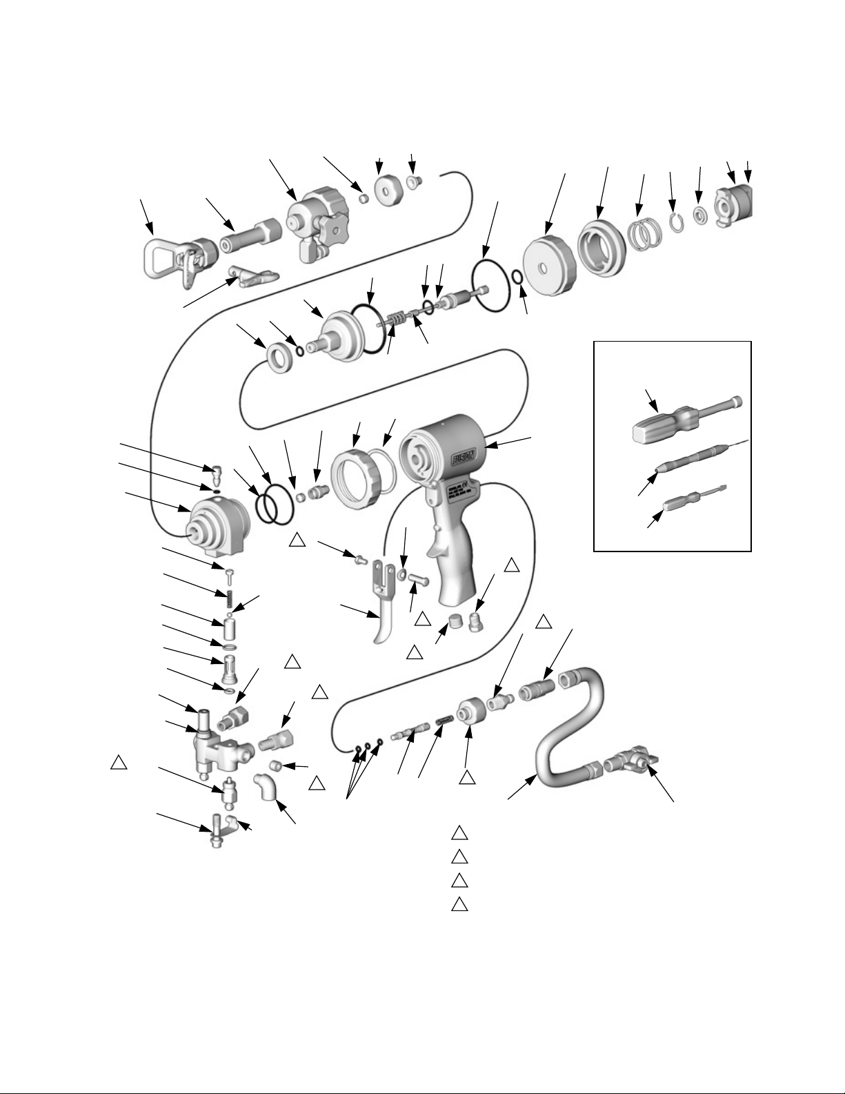
Parts
248597 and 248647 Solvent Purge Plural Component Spray Guns, and 248603 Conversion Kit
Parts
41
Ref. Part No. Description Qty.
28❖ 248643 SOLVENTPURGE ASSY.;
28a 15E111 . HOUSING 1
28b 15E130 . CAP, air 1
28c 113618 . GASKET, FFR 1
28d 15E137 . SEAT 1
28e 248641 . KIT, retainer 1
28f 15E114 . KNOB 1
28g 101366 . SCREW, set 2
28h 248648 . PACKING KIT, includes 6 o-rings 1
28j 191892 . ELBOW, 90° 1
28k 191872 . ADAPTER 1
28m 119796 . GASKET 1
40 248642 STATIC MIXER; includes items
40a 15E125 . HOUSING 1
40b 15E126 . MIXER, static 3 in. 1
40c 166969 . GASKET 1
40d 104892 . PACKING, o-ring 1
40d
Static Mixer Assembly
includes items 28a-28m
40a-40d
40a
40b
TI5034a
40c
28b
Solvent Purge Assembly
28m
28a
28c
28h
28d
28k
28j
1
1
28e
28g
TI5035a
28f
310648P 45
Page 46
Parts
248597 Solvent Purge Manual Spray Gun
‡44
‡*24
◆†‡7
63
†‡36b
‡36e
‡36d
‡*36g
†‡36a
†‡*36f
40
28❖
46*†‡ 25
39
18
31
14*★
15★
10★ 17★ 59★
60★
4★
3★
16*
32
9
61❖
19
18★
8
62❖
Supplied Tools
53
23‡
1
21*‡◆
46*†‡
35‡◆
11‡◆
20
34
TI3870a
54
36c‡
12e
56
5
2
4
22
13
2
6
29
1
1
30
1
48
12f
50
1
12c
1
24†‡
27
26
2
1
49
1
Torque to 125-135 in-lb (14-15 N•m).
2
Torque to 20-30 in-lb (2.3-3.4 N•m).
3
Torque to 32-40 ft-lb (43-54 N•m).
4
Torque to 35-45 in-lb (4-5 N•m).
51
TI4991b
‡36
†12a
12b
3
12d
12g
46 310648P
Page 47

248597 Solvent Purge Manual Spray Gun
Ref.
Ref.
No. Part No. Description Qty
1 248002 HANDLE 1
2 15B208 PLUG, air valve 1
3★ 15C374 ACTUATOR; safety 1
★ 15C390 BUSHING, safety 1
4
5 203953 SCREW; 10-24 x 3/8 in. (10 mm) 1
6 192272 PIN 1
7†‡◆ HOUSING, fluid 1
8 118145 SPRING, purge rod 1
9 XHD521 TIP, spray, RAC 1
10★ 15C373 CAP, rear 1
11‡◆
15B215 RING, lock 1
12 246012 MANIFOLD, fluid;
includes 12a-12g
12a† . MANIFOLD 1
12b 246356 . VALVE, fluid 2
12c 100139 . PLUG, pipe; 1/8-27 npt 2
12d 15B221 . BOLT; 5/16-24 1
12e 117634 . SWIVEL, B side; 1/8 npt(m) x
no. 6 JIC(f)
12f 117635 . SWIVEL, A side; 1/8 npt(m) x
no. 5 JIC(f)
12g 15B993 . SPRING, ring, lock 1
13 15B209 TRIGGER 1
14*★ 248136 O-RING, rod stop; package of 6 1
15★ 15C372 STOP, purge rod 1
16* 248135 O-RING, piston; package of 6 1
17★ 118144 SPRING, piston safety lock 1
18★ 248095 O-RING, purge rod; package of 6 1
19 248096 O-RING, piston shaft;
package of 6
20 248138 O-RING, housing, small;
package of 6
21‡◆* 248132 O-RING, housing, large;
package of 6
22 119626 MUFFLER 1
23‡ 15C378 NUT, rod seal, rear 1
24‡* 246354 O-RING; package of 6 1
25 15C377 NUT, mix module 1
26 117485 SPRING, air valve 1
27 15B202 SPOOL, air valve 1
28❖ SOLVENT PURGE ASSY.;
includes items 28a-j; see page 45
for parts
29 100721 PLUG, pipe; 1/4-18 npt 1
30 117509 QUICK-DISCONNECT, male, air;
1/4 npt(m)
31 248001 ROD, purge; includes 1 of item 18 1
32 15C371 PISTON 1
34 117661 VISE, pin; dual reversible chucks 1
35‡◆ 116550 RING, retaining 1
36‡ 246731 VALVE, check, A side; includes
36a-36g
246352 VALVE, check, B side; includes
36a-36g
36a‡† . HOUSING 1
36b‡† 15B214 . SCREW; 5/16-18 x
1/2 in. (13 mm)
36c‡ 104396 . BALL; carbide 1
36d‡ . SCREEN; see page 52 1
No. Part No. Description Qty
‡ 117490 . SPRING 1
36e
36f
‡* 248133 . O-RING, check valve face;
‡* 248129 . O-RING, check valve housing;
36g
37▲ 222385 TAG, warning; not shown 1
39 MODULE, mix, flat, direct impinge-
ment; see page 50
40 STATIC MIXER; includes items
40a-40d; see page 45 for parts
41 15E244 ADAPTER, static mixer;
see page 45
44‡
1
46
15C382 VALVE, cleanoff air 1
†‡* 248003 SEAL KIT, purge rod; includes 4
seals
48 117510 COUPLER, air line 1
49 15B772 HOSE, air; 1/4 npsm (fbe); 18 in.
(0.46 m)
50 112307 ELBOW, street;1/8 npt (m x f) 2
1
51 15B565 VALVE, ball; 1/4 npt (m x f) 1
53 117642 NUT DRIVER, hex; 5/16 1
1
54 118575 SCREWDRIVER; 1/8 blade 1
56 15C480 WASHER, wave 1
57■ 118665 LUBRICANT, Fusion Gun; 4 oz
(113 gram)
59★ 15D329 STOP, rod 1
60★ 115452 RING, retaining 1
61❖ 15E132 SPACER, piston 1
62❖ 15E133 SPACER, purge rod 1
63 XHD001 GUARD, tip 1
1
64 119386 DRILL BIT KIT, not shown 1
1
* These parts are only available in repair kits.To
1
select a kit, refer to Gun Repair Kits on page 52.
† These parts are not available singly.
‡ These parts are included in Front End Replacement
Kit 246875 (includes 1 of items 24 and 46).
★ These parts are included in Safety Stop Assembly
248028 (includes 1 of item 18).
▲ Replacement Danger and Warning labels, tags, and
1
cards are available at no cost.
■ Available in 248279 Kit, package of 10.
1
◆ Available in Fluid Housing Assembly Kit 248004.
❖ Available in Solvent Purge Conversion Kit 248603.
1
1
1
Parts
1
package of 6
1
package of 6
1
1
1
1
1
1
310648P 47
Page 48

Parts
248647 Machine Mount Spray Valve with Manual Solvent Purge
39
25
46*†‡
28
40
14*★
63
31
62❖
16*
15★
10★
17★
3★
4★
59★
60★
‡44
‡*24
†‡7
‡36;
see
detail
at right
†12a
9
61❖
19
8
35‡
11‡
32
18★
Check Valve
(36) Detail
1
†‡36b
23‡
21*‡
20
46*†‡
65
65
‡36e
‡36c
‡36d
*‡36g
†‡36a
*‡36f
12e
1
Supplied Tools
12f
1
53
12b
3
12d
12c
50
1
ti8661a
34
54
12g
1
Torque to 125-135 in-lb (14-15 N•m).
3
Torque to 32-40 ft-lb (43-54 N•m).
48 310648P
Page 49

248647 Machine Mount Spray Valve with Manual Solvent Purge
Ref.
Ref.
No. Part No. Description Qty
1 16H942 BODY, mechanical purge 1
★ 15C374 ACTUATOR; safety 1
3
4
★ 15C390 BUSHING, safety 1
7†‡◆ HOUSING, fluid 1
8 118145 SPRING, purge rod 1
9 XHD521 TIP, spray, RAC 1
10★ 15C373 CAP, rear 1
11‡◆
12 246012 MANIFOLD, fluid;
12a
12b 246356 . VALVE, fluid 2
12c 100139 . PLUG, pipe; 1/8-27 npt 2
12d 15B221 . BOLT; 5/16-24 1
12e 117634 . SWIVEL, B side; 1/8 npt(m) x
12f 117635 . SWIVEL, A side; 1/8 npt(m) x
12g 15B993 . SPRING, ring, lock 1
14*★ 248136 O-RING, rod stop; package of 6 1
15★ 15C372 STOP, purge rod 1
16* 248135 O-RING, piston; package of 6 1
17★ 118144 SPRING, piston safety lock 1
18★ 248095 O-RING, purge rod; package of 6 1
19 248096 O-RING, piston shaft;
20 248138 O-RING, housing, small;
21‡◆* 248132 O-RING, housing, large;
23‡ 15C378 NUT, rod seal, rear 1
24‡* 246354 O-RING; package of 6 1
25 15C377 NUT, mix module 1
28❖ SOLVENT PURGE ASSY.;
31 248001 ROD, purge; includes 1 of item 18 1
32 15C371 PISTON 1
34 117661 VISE, pin; dual reversible chucks 1
35‡◆ 116550 RING, retaining 1
36‡ 246731 VALVE, check, A side; includes
36a‡† . HOUSING 1
36b‡† 15B214 . SCREW; 5/16-18 x
36c‡ 104396 . BALL; carbide 1
36d‡ . SCREEN; see below 1
36e‡ 117490 . SPRING 1
36f‡* 248133 . O-RING, check valve face;
36g‡* 248129 . O-RING, check valve housing;
37▲ 222385 TAG, warning; not shown 1
15B215 RING, lock 1
includes 12a-12g
† . MANIFOLD 1
no. 6 JIC(f)
no. 5 JIC(f)
package of 6
package of 6
package of 6
includes items 28a-j; see page 45
for parts
36a-36g
246352 VALVE, check, B side; includes
36a-36g
1/2 in. (13 mm)
package of 6
package of 6
No. Part No. Description Qty
39 MODULE, mix, flat, direct impinge40 STATIC MIXER; includes items
41 15E244 ADAPTER, static mixer;
44‡
46†‡* 248003 SEAL KIT, purge rod; includes 4
1
50 112307 ELBOW, street;1/8 npt (m x f) 2
53 117642 NUT DRIVER, hex; 5/16 1
54 118575 SCREWDRIVER; 1/8 blade 1
57■ 118665 LUBRICANT, Fusion Gun; 4 oz
59★ 15D329 STOP, rod 1
1
60★ 115452 RING, retaining 1
61❖ 15E132 SPACER, piston 1
1
62❖ 15E133 SPACER, purge rod 1
63 XHD001 GUARD, tip 1
64 119386 DRILL BIT KIT, not shown 1
65 100139 PLUG, 1/8 NPT 3
* These parts are only available in repair kits.To
select a kit, refer to Gun Repair Kits, page 52.
1
† These parts are not available singly.
1
‡ These parts are included in Fluid Housing Assembly
1
1
1
1
1
1
1
Kit 246875 (includes 1 of items 24 and 46).
★ These parts are included in Safety Stop Assembly
248028 (includes 1 of item 18).
◆ Available in Fluid Housing Assembly Repair Kit
248004.
▲ Replacement Danger and Warning labels, tags, and
cards are available at no cost.
■ Available in 248279 Kit, package of 10.
Parts
1
ment, see page 50
1
40a-40d; see page 45 for parts
1
see page 45
15C382 VALVE, cleanoff air 1
1
seals
1
(113 gram)
310648P 49
Page 50

Parts
Slip-Fit Polycarballoy Mix Module Kits
Slip-Fit Polycarballoy Mix Module Part Numbering Code
Example
Part No.
XR3535 XR=Mechanical purge direct impingement, round pattern 35=Component A
XF3535 XF=Mechanical purge direct impingement, flat pattern
*** Some modules have multiple impingement ports (see below). Size is given as the equivalence of a single port.
FirstTwo Digits SecondTwo Dig-
its
impingement port
size (.035 in.).***
LastTwo Digits
35=Component B
impingement port
size (.035 in.).***
Direct Impingement Flat Pattern Guns
Slip-Fit Polycarballoy Mix Module
Kit (includes drill bits)
XF1313 1 #81 #67
XF1818 1 #77 #67
XF2323 1 #74 N/A
XF2929 1 #69 N/A
XF3535 2 #73 N/A
XF4747 2 #67 N/A
XF5757 3 #67 N/A
No. of Impingement
Ports
Impingement Port Drill
Bit Size, nominal**
Counterbore Drill
Bit Size, nominal**
**For further information, see identification chart under
Drill Bit Kits, page 51.
**For further information, see identification chart under
Drill Bit Kits, page 51.
Gun and Palm Grips
Applicator's comfort level with a spray gun is an essential part of the spray foam and polyurea installation process.The applicator's fatigue level can dramatically
affect the pattern and productivity of a project. 3M™
Gripping Material Technology is designed to:
• Reduce fatigue
• Provide comfort
• Give thermal protection
Gun Grips can be used alone to provide a strong secure
grip, or in combination with the Palm Grips to maximize
the comfort and anti-fatigueproperties and minimize the
applicator's grip strength.
Gun Grip Kit
Graco Gun Grips are designed to be used on Fusion
A, CS, or Probler®P2 Guns.
Kit Part No. Qty in Kit
17G542 10 Pack
17G543 50 Pack
17G544 100 Pack
Palm Grip Kit
Palm Grips are designed to adhere to any disposable/removable glove.
Kit Part No. Qty in Kit
17G545 10 Pack
17G546 50 Pack
17G547 100 Pack
®
50 310648P
Page 51

Drill Bit Kits
For cleaning gun ports and orifices and sizing mix module orifices. Illustrations are actual size, for comparison.
Not all sizes are used with your gun.
Parts
Kit Part No. Qty in Kit
Drill Bit Size
nominal in. mm
246623 3 #32 0.116 2.90
246810 3 7/64 0.109 2.77
246813 3 #39 .099 2.51
246812 3 #43 .089 2.26
246624 3 3/32 .094 2.39
246625 3 #44 .086 2.18
246811 3 2 mm .079 2.00
246626 6 #50 .070 1.78
246627 6 #53 .060 1.52
246809 6 #54 .055 1.40
246628 6 #55 .052 1.32
Illustration
246814* 6 #56 .046 1.18
246629* 6 #58 .042 1.07
246808* 6 #60 .040 1.02
246807† 6 #67 .032 0.81
246630† 6 #69 .029 0.74
246815† 6 #73 .024 0.61
276984† 6 #74 .023 0.57
246631† 6 #76 .020 0.51
246816† 6 #77 .018 0.46
246817* 6 #81 .013 0.33
* Included with gun, one each. † Included with gun in Drill Bit Kit 119386. Includes one of each.
310648P 51
Page 52

Gun Repair Kits
Gun Repair Kits
Read the chart left to right and top to bottom to find the quantity of each part in the kits.
Ref.
No.
14 248136 (6) 1
16 248135 (6) 1
18 248095 (6) 2
19 248096 (6) 1
20 248138 (6) 1
21 248132 (6) 1
24 246354 (6) 4*
28c 1
28h 248648 (6) 1
36f 248133 (6) 2 2
36g 248129 (6) 2 2
40c 1
40d 1
46 248003 (4) 2
Bulk O-ring
Kits, (qty)
246351
CheckValve
O-ring Kit
248887
Solvent Purge Gun
Complete O-ring Kit
*248647 only requires one #24. There will be three spares
when ordering the 248887 solvent purge gun complete o-ring
kit.
CheckValve Filter Screen Kits (10 per kit)
80 mesh filter screen is standard with gun.
246357 40 mesh (.015 in., 375 micron)
246358 60 mesh (.010 in., 238 micron)
246359 80 mesh (.007 in., 175 micron)
Drill Bit Kit
Drill Bit Kit 119386
20 piece drill bit set #61 - #80.
52 310648P
Page 53

Model 248647 Mounting Dimensions
Model 248647 Mounting Dimensions
Measurement Definition
in. (mm)
0.73
(18.54)
1.30 (33.0)
0.625 (15.88)
1.06 (26.92)
2 x 1/4-20
1 (25.4)
4xM5
3 x 1/8 npt
2x 0.127 (3.23)
ti4751b
0.625
(15.88)
310648P 53
Page 54

Technical Data
Technical Data
Category Data
Maximum Fluid Working Pressure 3500 psi (24.2 MPa, 242 bar)
Minimum Air Inlet Pressure 80 psi (0.55 MPa, 5.5 bar)
Maximum Air Inlet Pressure 130 psi (0.9 MPa, 9 bar)
Maximum Fluid Temperature 200° F (94° C)
Air Inlet Size 1/4 npt Quick Disconnect Nipple
Solvent Inlet Size 1/4-18 NPSM
A Component (ISO) Inlet Size -5 JIC; 1/2-20 UNF female swivel in 1/8 npt (f) port
B Component (Resin) Inlet Size -6 JIC; 9/16-18 UNF female swivel in 1/8 npt (f) port
Sound Pressure 70 dB(A), at 100 psi (0.7 MPa, 7 bar)
Sound Power, measured per ISO
9416-2
Length 9 in. (228 mm)
Height 8.1 in. (206 mm)
Width 3.5 in. (89 mm)
Weight 3.7 lb (1.68 kg)
Wetted Parts
79.9 dB(A), at 100 psi (0.7 MPa, 7 bar)
Aluminum, stainless steel, carbon steel, chemically resistant o-rings,
ultra-high molecular weight polyethylene (UHMWPE), Polycarballoy,
Nylon
Static Mixer 248642 Data
Inlet Thread 11/16-16 female straight thread
Outlet thread 11/16-16 male straight thread
Length 2.84 in. (72.2 mm)
Maximum Working Pressure 3500 psi (24.2 MPa, 242 bar)
Wetted Parts 303 stainless steel, Acetal plastic gaskets.
Disposable Static Mixer Adapter
15E244
Inlet Thread 11/16-16 female straight thread
Outlet thread 7/8-14 male straight thread with tapered bell
Usage Allows the use of disposable mixers, jackets, and RAC assemblies.
$OORWKHUEUDQGQDPHVRUPDUNVDUHXVHGIRULGHQWLILFDWLRQSXUSRVHVDQGDUHWUDGHPDUNVRIWKHLUUHVSHFWLYHRZQHUV
Data
54 310648P
Page 55

Technical Data
310648P 55
Page 56

Graco StandardWarranty
Graco warrants all equipment referenced in this document which is manufactured by Graco and bearing its name to be free from defects in
material and workmanship on the date of sale to the original purchaser for use. With the exception of any special, extended, or limited warranty
published by Graco, Graco will, for a period of twelve months from the date of sale, repair or replace any part of the equipment determined by
Graco to be defective.This warranty applies only when the equipment is installed, operated and maintained in accordance with Graco’s written
recommendations.
This warranty does not cover, and Graco shall not be liable for general wear and tear, or any malfunction, damage or wear caused by faulty
installation, misapplication, abrasion, corrosion, inadequate or improper maintenance, negligence, accident, tampering, or substitution of
non-Graco component parts. Nor shall Graco be liable for malfunction, damage or wear caused by the incompatibility of Graco equipment with
structures, accessories, equipment or materials not supplied by Graco, or the improper design, manufacture, installation, operation or
maintenance of structures, accessories, equipment or materials not supplied by Graco.
This warranty is conditioned upon the prepaid return of the equipment claimed to be defective to an authorized Graco distributor for verification of
the claimed defect. If the claimed defect is verified, Graco will repair or replace free of charge any defective parts. The equipment will be returned
to the original purchaser transportation prepaid. If inspection of the equipment does not disclose any defect in material or workmanship, repairs
will be made at a reasonable charge, which charges may include the costs of parts, labor, and transportation.
THISWARRANTY IS EXCLUSIVE, AND IS IN LIEU OF ANY OTHER WARRANTIES, EXPRESS OR IMPLIED, INCLUDING BUT NOT
LIMITEDTO WARRANTY OF MERCHANTABILITY OR WARRANTY OF FITNESS FOR A PARTICULAR PURPOSE.
Graco’s sole obligation and buyer’s sole remedy for any breach of warranty shall be as set forth above. The buyer agrees that no other remedy
(including, but not limited to, incidental or consequential damages for lost profits, lost sales, injury to person or property, or any other incidental or
consequential loss) shall be available. Any action for breach of warranty must be brought within two (2) years of the date of sale.
GRACO MAKES NO WARRANTY, AND DISCLAIMS ALL IMPLIED WARRANTIES OF MERCHANTABILITY AND FITNESS FOR A
PARTICULAR PURPOSE, IN CONNECTION WITH ACCESSORIES, EQUIPMENT, MATERIALS OR COMPONENTS SOLD BUT NOT
MANUFACTURED BY GRACO.These items sold, but not manufactured by Graco (such as electric motors, switches, hose, etc.), are subject to
the warranty, if any, of their manufacturer. Graco will provide purchaser with reasonable assistance in making any claim for breach of these
warranties.
In no event will Graco be liable for indirect, incidental, special or consequential damages resulting from Graco supplying equipment hereunder, or
the furnishing, performance, or use of any products or other goods sold hereto, whether due to a breach of contract, breach of warranty, the
negligence of Graco, or otherwise.
FOR GRACO CANADA CUSTOMERS
The Parties acknowledgethat they haverequired that the present document, as well as all documents, notices and legal proceedings entered into,
given or instituted pursuant hereto or relating directly or indirectly hereto, be drawn up in English. Les parties reconnaissent avoir convenuque la
rédaction du présente document sera en Anglais, ainsi que tous documents, avis et procédures judiciaires exécutés, donnés ou intentés, à la suite
de ou en rapport, directement ou indirectement, avec les procédures concernées.
Graco Information
For the latest information about Graco products, visit www.graco.com.
For patent information, see www.graco.com/patents.
TO PLACE AN ORDER, contact your Graco distributor or call to identify the nearest distributor.
Phone: 612-623-6921 or Toll Free: 1-800-328-0211 Fax: 612-378-3505
All written and visual data contained in this document reflects the latest product information available at the time of publication.
GRACO INC. AND SUBSIDIARIES • P.O. BOX 1441 • MINNEAPOLIS MN 55440-1441 • USA
Copyright 2004, Graco Inc. All Graco manufacturing locations are registered to ISO 9001.
Graco reserves the right to make changes at any time without notice.
Original instructions. This manual contains English. MM 310648
Graco Headquarters: Minneapolis
International Offices: Belgium, China, Japan, Korea
www.graco.com
Revision P, February 2016
 Loading...