

Page 1
Instructions–Parts List
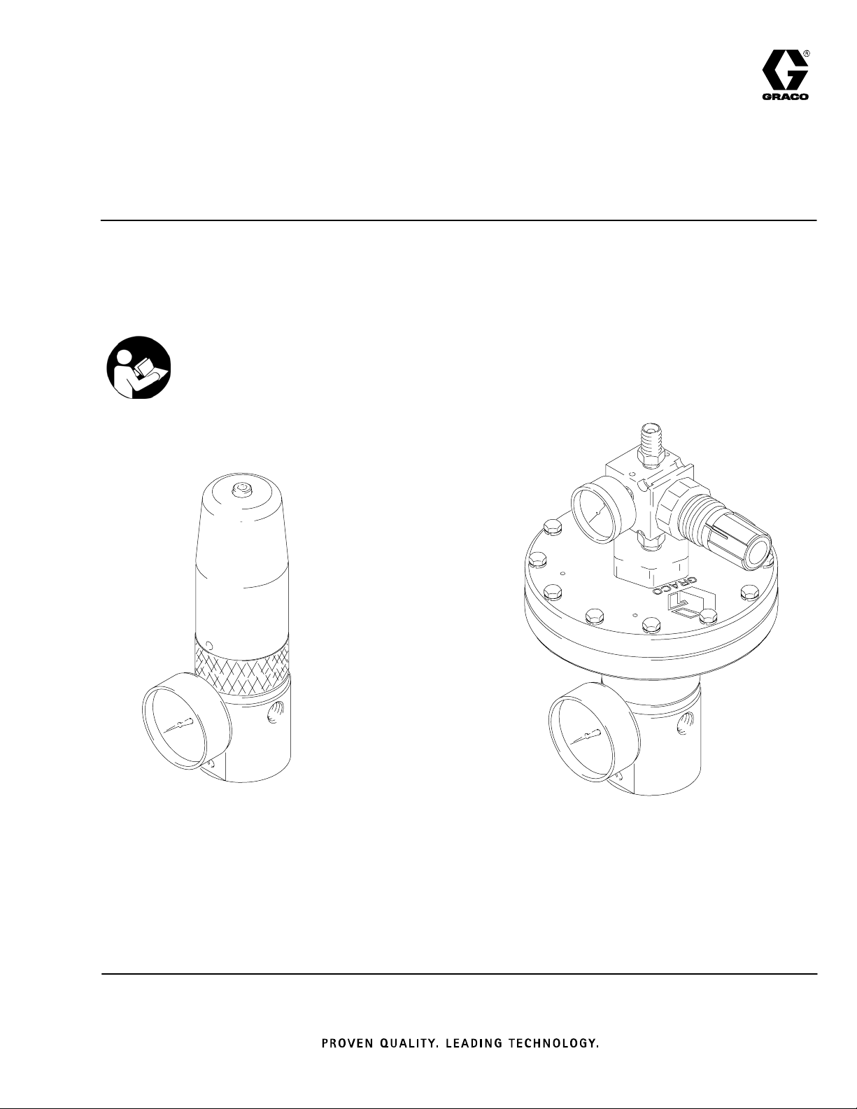
STAINLESS STEEL,
WATERBASE-COMPATIBLE, HIGH PRESSURE
Fluid Pressure Regulators
For precise downstream pressure and flow control.
Important Safety Instructions
Read all warnings and instructions in this manual.
Save these instructions.
See page 2 for List of Models and Table of Contents.
308647P
EN
Model 238890,
238892
(spring-operated)
U.S. Patent No. 4942899
06290
06288
Model 238894
(air-operated)
06540A
Page 2

Table of Contents
List of Models 2. . . . . . . . . . . . . . . . . . . . . . . . . . . . . . . . . .
Warnings 3. . . . . . . . . . . . . . . . . . . . . . . . . . . . . . . . . . . . . .
Installation 6. . . . . . . . . . . . . . . . . . . . . . . . . . . . . . . . . . . . .
Operation 8. . . . . . . . . . . . . . . . . . . . . . . . . . . . . . . . . . . . .
Troubleshooting 10. . . . . . . . . . . . . . . . . . . . . . . . . . . . . . .
Service 11. . . . . . . . . . . . . . . . . . . . . . . . . . . . . . . . . . . . . .
Parts
238889, 238890, 238891, and 238892 14. . . . . . . . . .
238893, 238894, 248090, and 255072 16. . . . . . . . . .
244734 18. . . . . . . . . . . . . . . . . . . . . . . . . . . . . . . . . . . . .
List of Models
Spring-Operated Models
Part No. Description Range
238889 with EZ Flush gauge port plug Medium
238890 with fluid pressure gauge Medium
238891 with EZ Flush gauge port plug High
238892 with fluid pressure gauge High
Technical Data 20. . . . . . . . . . . . . . . . . . . . . . . . . . . . . . . .
Performance Chart 21. . . . . . . . . . . . . . . . . . . . . . . . . . . .
Dimensional Drawings 23. . . . . . . . . . . . . . . . . . . . . . . . .
Graco Standard Warranty 24. . . . . . . . . . . . . . . . . . . . . .
Graco Information 24. . . . . . . . . . . . . . . . . . . . . . . . . . . . .
Maximum Fluid
Inlet Pressure
6000 psi
(41 MPa, 414 bar)
6000 psi
(41 MPa, 414 bar)
6000 psi
(41 MPa, 414 bar)
6000 psi
(41 MPa, 414 bar)
Regulated Fluid
Outlet Pressure
500–3000 psi
(3.4–21 MPa, 34–207 bar)
500–3000 psi
(3.4–21 MPa, 34–207 bar)
3000–5000 psi
(21–34 MPa, 207–345 bar)
3000–5000 psi
(21–34 MPa, 207–345 bar)
Air-Operated Models
Part No. Description Range
238893
238894
244734
248090
255072
2 308647
with EZ Flush gauge
port plug
with fluid pressure
gauge
with EZ Flush gauge
port plug
with fluid pressure
gauge (LASD)
high resolution with
fluid pressure gauge
Full
Full
Full
Full
Full
Maximum Inbound
Air Pressure
100 psi
(0.7 MPa, 7 bar)
100 psi
(0.7 MPa, 7 bar)
100 psi
(0.7 MPa, 7 bar)
100 psi
(0.7 MPa, 7 bar)
100 psi
(0.7 MPa, 7 bar)
Maximum Fluid
Inlet Pressure
6000 psi
(41 MPa, 414 bar)
6000 psi
(41 MPa, 414 bar)
6000 psi
(41 MPa, 414 bar)
6000 psi
(41 MPa, 414 bar)
6000 psi
(41 MPa, 414 bar)
Regulated Fluid
Outlet Pressure
500–4000 psi
(3.4–28 MPa, 34–276 bar)
500–4000 psi
(3.4–28 MPa, 34–276 bar)
500–4000 psi
(3.4–28 MPa, 34–276 bar)
500–4000 psi
(3.4–28 MPa, 34–276 bar)
500–2700 psi
(3.4–19 MPa, 34–190 bar)
Page 3

Symbols
Warning Symbol
WARNING
This symbol alerts you to the possibility of serious
injury or death if you do not follow the instructions.
WARNING
EQUIPMENT MISUSE HAZARD
Equipment misuse can cause the equipment to rupture or malfunction and result in serious injury.
INSTRUCTIONS
D This equipment is for professional use only.
D Read all instruction manuals, tags, and labels before operating the equipment.
D Use the equipment only for its intended purpose. If you are not sure, call your Graco distributor.
D Do not alter or modify this equipment. Use only genuine Graco parts and accessories.
D Check equipment daily. Repair or replace worn or damaged parts immediately.
Caution Symbol
CAUTION
This symbol alerts you to the possibility of damage to
or destruction of equipment if you do not follow the
instructions.
D Do not kink or over bend the hose or use the hose to pull equipment.
D Do not exceed the maximum working pressure of the lowest rated component in your system. Do
not exceed 6000 psi (41 MPa, 414 bar) maximum fluid inlet pressure of the regulator or the
maximum working pressure of the lowest-rated component in your system.
D Use fluids and solvents which are compatible with the equipment wetted parts. Refer to the
Technical Data section of all equipment manuals. Read the fluid and solvent manufacturer’s
warnings.
D Always wear protective eyewear, gloves, clothing, and respirator as recommended by the fluid and
solvent manufacturer.
D Comply with all applicable local, state, and national fire, electrical, and safety regulations.
3308647
Page 4
WARNING
SKIN INJECTION HAZARD
Spray from the gun, leaks, or ruptured components can inject fluid into your body and cause extremely
serious injury, including the need for amputation. Fluid splashed in the eyes or on the skin can also
cause serious injury.
D Fluid injected into the skin might look like just a cut, but it is a serious injury. Get immediate
surgical treatment.
D Do not point the gun at anyone or at any part of the body.
D Do not put your hand or fingers over the spray gun tip or extruder gun tip.
D Do not stop or deflect leaks with your hand, body, glove or rag.
D Always have the tip guard and the trigger guard on the gun when spraying.
D Check the gun diffuser operation weekly. Refer to the gun manual.
D Be sure the gun trigger safety operates before spraying.
D Lock the gun trigger safety when you stop dispensing.
D Follow the Pressure Relief Procedure on page 7 if the spray tip clogs and before cleaning,
checking, or servicing the equipment.
D Tighten all fluid connections before operating the equipment.
D Check the hoses, tubes, and couplings daily. Replace worn or damaged parts immediately. Do not
repair high pressure couplings; you must replace the entire hose.
D Fluid hoses must have spring guards on both ends to help protect them from rupture caused by
kinks or bends near the couplings.
HALOGENATED HYDROCARBON HAZARD
Never use 1,1,1–trichloroethane, methylene chloride, other halogenated hydrocarbon solvents, or
fluids containing such solvents in these regulators. In the unlikely event that there is a diaphragm
failure and the vent hole in the aluminum spring cap is plugged, a serious chemical reaction could
occur, with the possibility of explosion, which could cause death, serious injury, and/or substantial
property damage.
Consult your fluid suppliers to ensure that the fluids used are compatible with aluminum parts.
TOXIC FLUID HAZARD
Graco does not manufacture or supply the reactive chemical components that may be used in this
equipment and is not responsible for injury or property loss, damage, expense or claims (direct or
consequential) that arise from the use of such chemical components.
4 308647
Page 5

Notes
5308647
Page 6
Installation
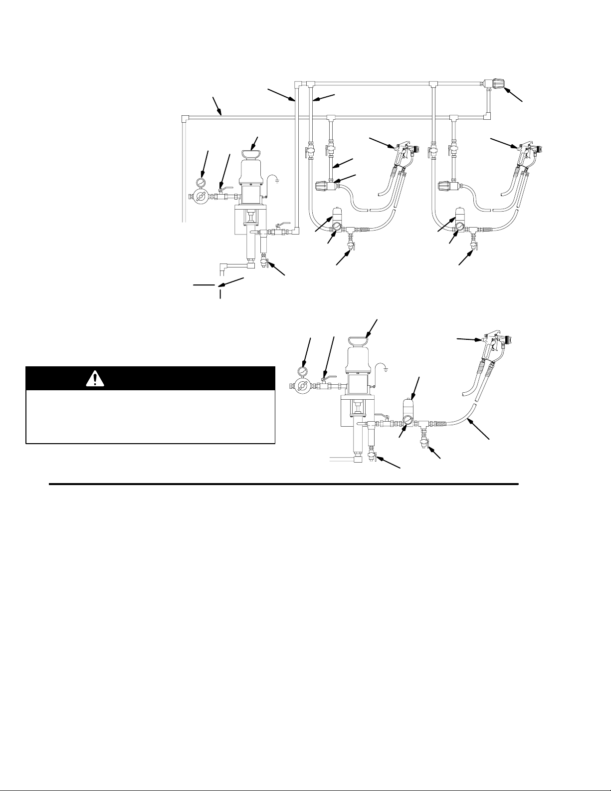
Multiple Circulating Spray Station
Key
A Air regulator
B Bleed-type master air valve
C Pump
D Fluid filter and drain valve
E Main fluid supply line
F Gun fluid supply line
G Fluid regulator
with fluid pressure gauge (H)
H Fluid pressure gauge
J Air-assisted airless spray gun
K Back pressure valve
L Fluid return line
M Main circulating line
N Fluid supply container
P Drain valve
WARNING
M
A
E
C
B
G
N
D
F
K
J
L
K
G
H
P
H
P
J
06461
Single Direct Spray Station
C
B
A
G
J
Do not use PTFE tape on pipe threads. Such use
could cause a hazardous condition due to loss of
grounding continuity. Also, if pieces of the tape break
off, the function of the regulator could be affected.
Fig. 1
The installations shown in Fig. 1 are only a guide for
selecting and installing a circulating or direct system;
they are not actual system designs. Contact your
Graco distributor for assistance in designing a system
to suit your needs.
NOTE: Before you install the regulator, thoroughly
flush the system to remove metal chips and other
contaminants. A fluid filter (D) of 60-mesh or finer
should always be installed upstream of the regulator.
Connections
Install the fluid regulator (G) in the spray gun fluid
supply line (F), as shown in the typical installation
drawings on this page. Connect only one spray gun
or dispensing valve to each fluid regulator.
H
D
Apply pipe sealant to the male pipe threads, and
connect the fluid supply line (F) to the fluid regulator’s
3/8 npt(f) inlet. Connect the line from the gun (J) to the
fluid regulator’s 3/8 npt(f) outlet. Install the gauge or
plug into the 1/4 npt(f) gauge port.
Make sure the direction of fluid flow agrees with the IN
and OUT markings on the regulator body.
P
F
06462
Flush the System
The regulator was tested in lightweight oil. Flush the
entire system with a solvent compatible with the fluid
being dispensed. Then test the system.
Mounting Bracket
A Mounting Bracket is available for mounting the
regulator. Order Part 222515 for the bracket and
mounting hardware.
6 308647
Page 7

Installation
Grounding the System
WARNING
FIRE AND EXPLOSION HAZARD
Before operating the fluid pressure
regulator, ground the system as
explained below.
Pump: Use a ground wire and clamp. Loosen the
grounding lug locknut (W) and washer (X). Insert one
end of a 1.5 mm@ (12 ga) minimum ground wire (Y)
into the slot in lug (Z) and tighten the locknut securely.
Connect the other end of the wire to a true earth
ground. Order Part 237569 Ground Wire and Clamp.
W
X
Y
Z
0864
Fig. 2
Air and fluid hoses: Use only electrically conductive
hoses.
Heaters, if used: See the heater instruction manual.
Air compressor: Follow manufacturer’s
recommendations.
Spray gun: Ground through connection to a properly
grounded fluid hose and pump.
Fluid supply container: Follow your local code.
Object being sprayed: Follow your local code.
Solvent pails used when flushing: Follow your local
code. Use only metal pails, which are conductive,
placed on a grounded surface. Do not place the pail on
a nonconductive surface, such as paper or cardboard,
which interrupts the grounding continuity.
To maintain grounding continuity when flushing or
relieving pressure, hold a metal part of the spray gun
firmly to the side of a grounded metal pail, then trigger
the gun.
Pressure Relief Procedure
WARNING
SKIN INJECTION HAZARD
The system pressure must be manually
relieved to prevent the system from
starting or spraying accidentally. Fluid
under high pressure can be injected through the
skin and cause serious injury. To reduce the risk of
an injury from injection, splashing fluid, or moving
parts, follow the Pressure Relief Procedure
whenever you
D Are instructed to relieve the pressure
D Stop spraying
D Check or service any of the system equipment
D Install or clean the spray tips
7308647
Page 8
Operation
Adjusting the System Pressure
CAUTION
D The new system must be cleaned and tested
thoroughly before admitting fluid to the regulator
to avoid contaminants clogging or damaging the
regulator.
D Always use the lowest possible air and fluid
pressures for your application. High pressures
can cause premature spray tip, regulator, and
pump wear.
NOTES:
D The fluid pressure regulator controls pressure
downstream from its outlet.
D If you are using an accessory fluid pressure gauge
(H in Fig. 1), relieve the spray gun line pressure
after you reduce the regulator pressure to ensure a
correct gauge reading.
2. Adjust the pump air pressure and fluid regulator for
the desired spray pattern. Use the lowest possible
air and fluid pressures for your application. For
optimum performance, the inbound fluid pressure
should be at least 500 psi (3.4 MPa, 34 bar) above
the regulated fluid pressure.
NOTE: Do not exceed a 2000 psi (14 MPa,
138 bar) pressure drop between the regulator inlet
and outlet. Excessive pressure drop will cause
premature regulator component wear.
For example: With 3500 psi (24.5 MPa, 245 bar)
to the regulator, the minimum regulated outlet
pressure would be 1500 psi (10.5 MPa, 105 bar).
3. In a circulating system, also adjust the back
pressure valve (K).
4. Record all the settings for future reference.
Cleaning the Regulator
1. Make a note of the proper way to adjust pressure,
from the following descriptions:
D On a spring-operated regulator, turn the
adjusting screw (10) counterclockwise to
decrease pressure and clockwise to increase
pressure to the spray gun or extruder gun.
D On an air-operated regulator, increase supply
air pressure to increase fluid pressure.
Decrease supply air pressure to decrease fluid
pressure. Supply air up to 100 psi (0.7 MPa,
7 bar). See the chart on page 20 for air versus
fluid pressure.
NOTE: Air-operated regulator Models 238893 and
238894 are provided with an air supply regulator
(31) to control the fluid set pressure. For
increased sensitivity in pressure set point
performance, an alternative air regulator, such as
Part 206197, may be used. This alternative air
regulator uses a sensitive diaphragm design to
maintain a higher, more accurate air pressure
setting.
Do not allow fluid to settle in the system.
Flush the regulator whenever the rest of the system is
flushed (see page 9). Before you flush the system,
follow the Pressure Relief Procedure on page 7,
then completely decrease the regulated fluid pressure.
See step 1 in Adjusting the System Pressure, at left.
Before you remove the regulator for thorough cleaning
and inspection, follow the Pressure Relief Procedure
on page 7. Then remove the regulator, clean it, and
inspect all parts.
8 308647
Page 9

Operation
Flushing
D Flush before changing colors, before fluid can dry in
the equipment, at the end of the day, before storing,
and before repairing equipment.
D Flush at the lowest pressure possible. Check
connectors for leaks and tighten as necessary.
D Flush with a fluid that is compatible with the fluid
being dispensed and the equipment wetted parts.
1. Record the pressure adjustment setting of the fluid
regulator before flushing.
2. Shut off the pump and relieve fluid pressure in the
system by triggering the gun and opening the back
pressure regulator or other bypass valve.
3. Never exceed the maximum working pressure of
the lowest rated system component. Remove the
gauge if the flushing pressure will exceed the
gauge range.
4. Open the fluid regulator fully.
a. Spring Operated Regulators Only: Open the
fluid regulator by turning the adjusting screw
(10) fully clockwise.
b. Air Operated Regulator Only: Increase the air
regulator setting to fully open the fluid
regulator. You will have to reset the fluid
regulator’s pressure setting after flushing.
5. Supply solvent to the system. Set pump to the
lowest possible pressure, and start pump.
6. Flush until thoroughly clean.
7. Adjust the fluid regulator to the desired setting.
a. Spring Operated Regulators Only: Turn the
adjustment screw (10) counterclockwise to
return to the desired pressure setting.
b. Air Operated Regulator Only: Adjust the air
regulator to return to the desired fluid pressure
setting.
9308647
Page 10

Troubleshooting
WARNING
To reduce the risk of serious bodily injury, including
skin injection, splashing in the eyes or on the skin,
or injury from moving parts, always follow the Pres-
sure Relief Procedure on page 5 whenever the
pump is shut off, before installing, cleaning, adjusting, removing, or servicing the valve or any part of
the system, and whenever you stop dispensing.
NOTE: Check all possible solutions in the chart below
before you disassemble the regulator.
Problem
No pressure regulation Damaged diaphragm Replace diaphragm.
No fluid flow Damaged valve actuator Replace valve actuator.
Pressure creeps above
setting
Pressure drops below
setting
Cause Solution
Leaking or dirty seat Replace cartridge, or clean seat.
Metal chip or contamination
between ball and seat
Damaged diaphragm Replace diaphragm.
Damaged o-ring or improper seal Replace the o-ring under the seat.
Damaged or clogged air regulator or
line (air-operated regulator only)
Leaking or dirty seat Replace cartridge, or clean seat.
Large change in inlet pressure Stabilize regulator inlet pressure.
Empty/clogged supply line Fill/flush supply line.
Damaged or clogged air regulator or
line (air-operated regulator only)
Replace cartridge, or clean seat area.
Clear obstruction in line. Service regulator if necessary.
Clear obstruction in line. Service regulator if necessary.
Using valve beyond its rated flow
capacity
Large change in inlet pressure Stabilize regulator inlet pressure.
Fluid leaks from spring
housing
Chatter Excessive pressure differential
10 308647
Loose fluid housing Tighten the four cap screws.
Damaged diaphragm Replace diaphragm.
between pump and gun
Excessive flow rate Reduce fluid flow through regulator.
Install valve for each spray gun or
dispensing valve.
Reduce pump pressure to not more than
2000 psi (14 MPa, 138 bar) greater than
required gun pressure.
Connect only one spray gun or dispensing valve to each fluid regulator.
Page 11

Service
Service Kits
For the Fluid Diaphragm Repair Kit, order Part 238747.
Parts included in this kit are marked with an asterisk,
for example (7*), in the Parts Drawings and Lists on
pages 14 and 16.
For the Cartridge Repair Kit, order Part 238748 for all
models except 248090. Parts included in this kit are
marked with a dagger, for example (3{), in the Parts
Drawings and Lists on pages 14 and 16.
For the Cartridge Repair Kit for 248090, order Part
248098. Parts included in this kit are marked with a
checkmark, for example (3n), in the Parts Drawings
and Lists on pages 14 and 16.
To convert from a spring-operated to an air-operated
regulator, order the Air-Operated Conversion Kit, Part
238749. Parts included in this kit are marked with a
double dagger, for example (37}), in the Parts
Drawings and Lists on pages 14 and 16.
NOTE: To convert from a medium-pressure-range,
spring-operated model to a high-pressure-range,
spring-operated model (or vice versa), order the
appropriate spring (11) from the Parts List on
page 15.
Installing the Air-Operated Conversion Kit
(See Parts Drawings on pages 14–16)
1. Relieve the pressure.
WARNING
To reduce the risk of serious injury whenever you
are instructed to relieve pressure, always follow the
Pressure Relief Procedure on page 7.
2. On the spring-operated regulator, turn the
adjusting screw (10) counterclockwise until it is
loose enough to fully relieve the spring tension.
3. Use a strap wrench or an equivalent wrench to
loosen and remove the spring cover (2), spring
retainers (6 and 27), and spring (11).
4. Place the stabilizing spring (22) of the air-operated
regulator on the piston rod (6). Install the
conversion kit assembly onto the backing plate (8).
Torque to 15 to 20 ft-lb (20 to 27 NSm).
5. Plumb an air line up to the 1/4 npt(m) threads of
the nipple (35) on the air regulator.
6. Flush the system (see page 9), and set the
regulator pressure by following the procedure in
Adjusting the System Pressure on page 8.
11308647
Page 12

Service
Replacing the Fluid Diaphragms
See Fig. 3, and follow the steps below. For parts that
are not called out in Fig. 3, see the Parts Drawing on
page 14.
1. Relieve the pressure, and remove the regulator
from the fluid line.
WARNING
To reduce the risk of serious injury whenever you
are instructed to relieve pressure, always follow the
Pressure Relief Procedure on page 7.
2. Turn the adjusting screw (10) counterclockwise
until it is loose to fully relieve the spring tension.
3. Remove the four base housing screws (9) from the
base housing (4), and pull the base housing free of
the backing plate (8).
4. Remove the diaphragm and valve actuator
subassembly (1, 7, 12, 13, and 19).
5. Clean and inspect the bore in the backing plate (8)
for wear, and replace it if necessary.
6. Remove the o-ring (17) from the groove in the
base housing (4), clean and inspect the base
housing, and replace if necessary.
7. Install a new o-ring (17) in the groove in the base
housing (4).
8. Lightly lubricate the backing plate (8) bore and
plunger (7) with a lithium-based grease.
9. Install the new, pre-assembled diaphragm
subassembly into the backing plate (8).
NOTE: The diaphragms will have a bow in them
before you install them.
10. Align the holes in the diaphragms with the backing
plate (8).
11. Install the backing plate/diaphragms assembly
over the base housing (4). Hold the backing plate
(8) tightly against the base housing, and install the
four base housing screws (9).
12. Torque the base housing screws (9) first to 20 to
25 ft-lb (27 to 34 NSm), then to 30 to 35 ft-lb (41 to
48 NSm) in the sequence shown in Fig. 3.
2
backing
plate (8)
diaphragm
and valve
actuator
subassembly
Fig. 3
10
cartridge
assembly
Torque Sequence for Regulator
17
3
5
Base Housing Screws (9)
4
4
2
9
1
3
06656
12 308647
Page 13

Service
Replacing the Cartridge
See Fig. 3, and follow the steps below. For parts that
are not called out in Fig. 3, see the Parts Drawing on
page 14.
CAUTION
Handle the hard carbide parts, which are the ball
(16), valve actuator (1), and valve seat (14), carefully
to avoid damaging them.
1. Relieve the pressure.
WARNING
To reduce the risk of serious injury whenever you
are instructed to relieve pressure, always follow the
Pressure Relief Procedure on page 7.
2. Remove the cartridge assembly by loosening the
valve housing (5) with a 6 mm hex wrench and
pulling the cartridge assembly out of the base
housing (4).
NOTE: The retaining nut (3) often loosens when
removing the cartridge assembly from the base
housing. Be sure to re–torque as described in
step 4.
3. Inspect and clean the internal walls of the base
housing (4).
NOTE: Be careful that you do not scrape or
gouge the internal walls of the base housing,
because they are sealing surfaces.
4. Re-torque the retaining nut (3) to 140 to 160 in-lb
(16 to 18 NSm).
NOTE: You must re-torque the retaining nut
before you install it in the base housing in step 5.
5. Install the new cartridge assembly in the base
housing (4), and torque the valve housing (5) to 30
to 35 ft-lb (41 to 48 NSm).
NOTE: The valve seat (14) is double sided and
may be reversed for extended life. The o-rings
(15, 18 and 20) and ball (16) must be replaced.
13308647
Page 14

Parts Drawing
Models 238889, 238890, 238891, and 238892
238889 with EZ Flush gauge port plug
238890 with fluid pressure gauge
Spring-Operated Regulator
500 to 3000 psi (3.4 to 21 MPa, 34 to 207 bar)
Regulated Fluid Outlet Pressure
10
6
2
3
6
27
238891 with EZ Flush gauge port plug
238892 with fluid pressure gauge
Spring-Operated Regulator
3000 to 5000 psi (21 to 34 MPa, 207 to 345 bar)
Regulated Fluid Outlet Pressure
7*
6
12*
13*
19*
1*
1
17*
29
30
4
6
11
6
8
DETAIL
Torque Sequence for Regulator
Base Housing Screws (9)
4
2
1
3
3{
2
14{
15{
28
9
5
20{
18{
7
7
16{
21{
5{
4
06289
Torque to 25 to 30 in-lb (2.8 to 3.4 NSm).
1
Torque to 140 to 160 in-lb (16 to 18 NSm).
2
Torque to 10 to 20 ft-lb (14 to 27 NSm).
3
Torque to 30 to 35 ft-lb (41 to 48 NSm).
4
Torque first to 20 to 25 ft-lb (27 to 34 NSm), then to 30 to 35
5
ft-lb (41 to 48 NSm) in the sequence shown in DETAIL at left.
Apply lithium-based grease when reassembling.
6
Apply a fluid-compatible grease to aid in reassembly.
7
14 308647
Page 15

Parts List
Models 238889, 238890, 238891, and 238892
Ref. Part No. Description Qty.
1 * ACTUATOR 1
2 238858 COVER, spring 1
3{ 191577 NUT, spring retainer 1
4 191578 BASE HOUSING; sst 1
5{ 191579 VALVE HOUSING; sst 1
6 191580 RETAINER, spring, guide 1
7 * PLUNGER, spring 1
8 191583 PLATE, backing 1
9 113623 BASE HOUSING SCREW,
cap, socket-head; M10 x 1.5 x 70 4
10 113624 ADJUSTING SCREW, cap,
socket-head; M8 x 1.25 x 45 1
11} 113625 SPRING, compression; red
for Models 238889 & 238890 1
113626 SPRING, compression; yellow
for Models 238891 & 238892 1
12 * DIAPHRAGM, regulator; TPE
cream colored 1
13 * DIAPHRAGM, regulator; PTFE
white 1
14{ 191914 SEAT, valve 1
15{ 113651 O-RING, packing; PTFE 1
16{ 112365 BALL 1
17* 109213 O-RING, packing; PTFE 025 1
Ref. Part No. Description Qty.
18{ 107079 O-RING, packing; PTFE 019 1
19 * O-RING, packing; PTFE 013 1
20{ 109450 O-RING, packing; PTFE 016 1
21{ 111858 SPRING, compression 1
23 113634 WRENCH, hex; 6 mm
(not shown) 1
27 191919 RETAINER, spring, sleeve 1
28 113641 GAUGE, pressure
for Model 238890 1
113654 GAUGE, pressure
for Model 238892 1
29 238896 PLUG, EZ Flush (includes Ref. 30)
for Models 238889 & 238891 1
30 107509 O-RING, packing; PTFE 007 1
* Included in Fluid Diaphragm Repair Kit 238747
{ Included in Cartridge Repair Kit 238748
} To convert to a higher or lower pressure range,
order one of the following compression springs:
113625 500 to 3000 psi
(3.4 to 21 MPa, 34 to 207 bar
113626 3000 to 5000 psi
(21 to 34 MPa, 207 to 345 bar)
15308647
Page 16

Parts Drawing
Models 238893, 238894, 248090, and 255072
}33
}28
8
}36
}37
}30
40
}35
}31
}34
32}
11}
238893 with EZ Flush gauge port plug
238894 with fluid pressure gauge
}2
3
248090 with fluid pressure gauge for
LASD material
255072 High Resolution
6
7
}6
Air-Operated Regulator
100 psi (0.7 MPa, 7 bar)
Maximum Inbound Air Pressure
500 to 4000 psi (3.4 to 28 MPa, 34 to 276 bar)
}22
Regulated Fluid Outlet Pressure
8
7*
7
12*
13*
19*
DETAIL OF MODEL 248090
41
42
4
39
1*
17*
1
38
4
42
41
}29
3
DETAIL
Torque Sequence for Regulator
Base Housing Screws (9)
4
2
1
3
25
3{n
2
14{n
15{n
20{n
5
9
18{n
7
7
25
16{n
21{n
5{n
4
06287
Torque to 25 to 30 in-lb (2.8 to 3.4 NSm).
1
Torque to 140 to 160 in-lb (16 to 18 NSm).
2
Torque to 15 to 20 ft-lb (20 to 27 NSm).
3
4
Torque to 30 to 35 ft-lb (41 to 48 NSm).
Torque first to 20 to 25 ft-lb (27 to 34 NSm), then to 30 to 35
5
ft-lb (41 to 48 NSm) in the sequence shown in DETAIL at left.
First torque to 30–33 in-lb (3.4–3.7 NSm) in alternating pattern
6
then torque to 68–72 in-lb (7.7–8.1 NSm) in alternating pattern.
Apply lithium-based grease when reassembling.
7
Torque to 75 to 80 in-lb (8.4 to 9.0 NSm).
8
16 308647
Page 17

Parts List
Models 238893, 238894, 248090, and 255072
Ref.
No. Part No. Description Qty.
1 * ACTUATOR 1
2} 191584 HOUSING ADAPTER 1
3{n 191577 NUT, spring retainer 1
4 191578 HOUSING, base, for Models
238893 and 238894 1
197952 HOUSING, base,
for Model 248090 1
15J923 HOUSING, base,
for Model 255072 1
5{n 191579 VALVE HOUSING, sst 1
15J924 VALVE HOUSING,
for Model 255072 1
6} 191585 ROD, piston, for Models 238893,
238894, and 248090 1
15J920 ROD, piston, for Model 255072 1
7 * PLUNGER, spring 1
8 191583 PLATE, backing 1
9 113623 BASE HOUSING SCREW,
cap, socket-head; M10 x 1.5 x 70 4
11}z 114104 SCREW, machine 12
12 * DIAPHRAGM, regulator; TPE
cream colored 1
13 * DIAPHRAGM, regulator; PTFE 1
white 1
14{n 191914 SEAT, valve 1
15{n 113651 O-RING, packing; PTFE 1
16{ 112365 BALL, for Models 238893 and
238894 1
16n 15D092 BALL, for Models 248090 and
255072 1
17* 109213 O-RING, packing; PTFE 025 1
18{n 107079 O-RING, packing; PTFE 019 1
19 * O-RING, packing; PTFE 013 1
20{n 109450 O-RING, packing; PTFE 016 1
Ref.
No. Part No. Description Qty.
21{n 111858 SPRING, compression 1
22} 160062 SPRING, stabilizing 1
25 113654 GAUGE, pressure
for Models 238894 and 248090 1
28}z ––– COVER, diaphragm 1
29}z ––– HOUSING, diaphragm 1
30} 100326 SCREW, machine 1
31} 110341 REGULATOR, air 1
32} 100403 PLUG, pipe 1
33} 108190 GAUGE, pressure, air 1
34} 103656 NIPPLE, pipe, hex 1
35} 151519 NIPPLE, reducing; 1/4 x 1/8 npt 1
36} 192194 WASHER, support 1
15J921 WASHER, for Model 255072 1
37}z 180979 DIAPHRAGM; nylon, for Models
238893, 238894, and 248090 1
38 238896 PLUG, EZ Flush (includes Ref. 39)
for Model 238893 1
39 107509 O-RING, packing; PTFE 007
for Model 238893 1
40 15J922 RING, diaphragm,
for Model 255072 1
41 198241 PLUG, pressure for Models
248090 and 255072 2
42 111457 PACKING, o-ring; PTFE 012 for
Models 248090 and 255072 2
* Included in Fluid Diaphragm Repair Kit 238747
{ Included in Cartridge Repair Kit 238748
} Included in Air-Operated Conversion Kit 238749
n Included in Cartridge Repair Kit 248098
z Included in Diaphragm Housing Repair Kit
16P596.
17308647
Page 18

Parts Drawing
Model 244734
40
11}
}28
244734 with EZ Flush gauge port plug
5
Air-Operated Regulator, Full Range
100 psi (0.7 MPa, 7 bar)
Maximum Inbound Air Pressure
500 to 4000 psi (3.4 to 28 MPa, 34 to 276 bar)
Regulated Fluid Outlet Pressure
}37
}30
8
8
}36
7*
6
}29
3
12*
13*
}2
3
6
}6
}22
Torque to 25 to 30 in-lb (2.8 to 3.4 NSm).
1
Torque to 140 to 160 in-lb (16 to 18 NSm).
2
Torque to 15 to 20 ft-lb (20 to 27 NSm).
3
4
Torque to 30 to 35 ft-lb (41 to 48 NSm).
First torque to 30–33 in-lb (3.4–3.7 NSm) in alternating pattern
5
then torque to 68–72 in-lb (7.7–8.1 NSm) in alternating pattern.
Apply lithium-based grease when reassembling.
6
Torque first to 20 to 25 ft-lb (27 to 34 NSm), then to 30 to 35
7
ft-lb (41 to 48 NSm) in the sequence shown in DETAIL at right.
Torque to 75 to 80 in-lb (8.4 to 9.0 NSm).
8
38
41
1*
42
39
3{
7
9
20{
18{
16{
5{
Torque Sequence for Regulator
Base Housing Screws (9)
DETAIL
2
19*
17*
14{
15{
21{
1
4
42
41
2
6
6
4
TI1373
3
18 308647
4
1
Page 19

Parts List
Model 244734
Ref.
No. Part No. Description Qty.
1 * ACTUATOR 1
2} 191584 HOUSING ADAPTER 1
3{ 191577 NUT, spring retainer 1
4 197952 REGULATOR HOUSING 1
5{ 191579 VALVE HOUSING; sst 1
6} 191585 ROD, piston 1
7 * PLUNGER, spring 1
8 191583 PLATE, backing 1
9 113623 BASE HOUSING SCREW,
cap, socket-head; M10 x 1.5 x 70 4
11}z 114104 SCREW, machine; 1/4–20 x 1.0 12
12 * DIAPHRAGM, regulator; PTE
cream colored 1
13 * DIAPHRAGM, regulator; PTFE
white 1
14{ 191914 SEAT, valve 1
15{ 113651 O-RING, packing; PTFE 1
16{ 15D092 BALL 1
17* 109213 O-RING, packing; PTFE 025 1
Ref.
No. Part No. Description Qty.
18{ 107079 O-RING, packing; PTFE 019 1
19 * O-RING, packing; PTFE 013 1
20{ 109450 O-RING, packing; PTFE 016 1
21{ 111858 SPRING, compression 1
22} 160062 SPRING, stabilizing 1
28}z ––– COVER, diaphragm 1
29}z ––– HOUSING, diaphragm 1
30} 100326 SCREW, machine; 1/4–20 x 1/2 1
36} 192194 WASHER, support 1
37}z 180979 DIAPHRAGM; nylon 1
38 238896 PLUG, EZ Flush (includes Ref. 39) 1
39 107509 O-RING, packing; PTFE 007 1
40 198171 FITTING, elbow 1
41 198241 PLUG, pressure 2
42 111457 PACKING, o-ring; PTFE 012 2
* Included in Fluid Diaphragm Repair Kit 238747
{ Included in Cartridge Repair Kit 248098
} Included in Air-Operated Conversion Kit 238749
z Included in Diaphragm Housing Repair Kit
16P596.
19308647
Page 20

Technical Data
fluid
Model 238890
spring operated, with
fluid pressure gauge
Model 238889
spring operated, with
EZ Flush plug
Maximum fluid
inlet pressure
Regulated fluid
outlet pressure
range
Maximum inbound
air pressure
Fluid inlet/outlet
size
Gauge port size 1/4 npt(f) 1/4 npt(f) 1/4 npt(f) 1/4 npt(f)
Fluid pressure
gauge (Models
238890, 238892,
and 238894)
Maximum flow
(in 65 cp material)
Maximum fluid
viscosity
Maximum operating temperature
Weight (with gauge) 7.0 lb (3.2 kg) 7.0 lb (3.2 kg) 11.7 lb (5.3 kg) 11.7 lb (5.3 kg)
Fluid diaphragms PTFE with TPE
Wetted parts (all
models)
Adjustment tool
(spring-operated
models)
6000 psi
(41 MPa, 414 bar)
500–3000 psi
(3.4–21 MPa,
34–207 bar)
–– –– 100 psi
3/8 npt(f) 3/8 npt(f) 3/8 npt(f)
0–3000 psi
(0–21 MPa,
0–207 bar)
2 gpm (7.6 lpm) 2 gpm (7.6 lpm) 2 gpm (7.6 lpm) 2 gpm (7.6 lpm)
up to 15,000 cp up to 15,000 cp up to 15,000 cp up to 15,000 cp
120_ F (50_ C) 120_ F (50_ C) 120_ F (50_ C) 120_ F (50_ C)
backing
304, 316, 17–4 passivated SST, nickel– and cobalt–bound tungsten carbide, PTFE for all
models; ceramic for model 248090, 244734, and 255072 only.
6 mm hex wrench 6 mm hex wrench –– ––
Model 238892
spring operated, with
fluid pressure gauge
Model 238891
spring operated, with
EZ Flush plug
6000 psi
(41 MPa, 414 bar)
3000–5000 psi
(21–34 MPa,
207–345 bar)
0–5000 psi
(0–34 MPa,
0–345 bar)
PTFE with TPE
backing
Models 238894,
248090, and 255072
air operated, with
pressure gauge
Model 238893
air operated, with EZ
Flush plug
6000 psi
(41 MPa, 414 bar)
500–4000 psi
(3.4–28 MPa,
34–276 bar)
(0.7 MPa, 7 bar)
1/2 npt(f) for 248090
0–5000 psi
(0–34 MPa,
0–345 bar)
PTFE with TPE
backing
Model 244734
air operated, with
pressure sensor
ports
6000 psi
(41 MPa, 414 bar)
500–4000 psi
(3.4–28 MPa,
34–276 bar)
100 psi
(0.7 MPa, 7 bar)
1/2 npt(f)
––
PTFE with TPE
backing
Air Requirements for Air-Operated Regulators
(Models 238893, 238894, 248090, and 255072)
The following table shows the approximate air pressure needed to regulate the air-operated regulator to a given
fluid outlet pressure.
Regulated Fluid Outlet Pressure
Models 238894, 248090,
and 255072 Model 255072
20 308647
Air Pressure
psi MPa bar psi MPa bar psi MPa bar
28 0.19 1.9 1000 7 69 550 4 40
49 0.34 3.4 2000 14 138 1150 8 80
70 0.48 4.8 3000 21 207 1800 12 120
90 0.62 6.2 4000 28 276 2450 17 170
100 0.68 6.8 4000 28 276 2700 19 190
Page 21

psi
(MPa, bar)
6000
(41, 414)
5000
(34, 345)
4000
(28, 276)
3000
(21, 207)
Performance Chart
Fluid Pressure Regulators,
Models 238889 through 238894 and 248090
2000
(14, 138)
REGULATED (outbound) FLUID PRESSURE
1000
(7, 69)
0
0.0 0.5 1.0 1.5 2.0
gpm
(lpm)
(1.9)
Test Conditions
Regulators tested in oil at 70_ F (21_ C) and at
6000 psi (41 MPa, 414 bar) inbound fluid pressure.
(3.8) (5.7) (7.6)
FLUID FLOW
Key
65 cp oil
3000 cp oil
21308647
Page 22

Notes
22 308647
Page 23

Dimensional Drawings
Models 238889 and 238891 with port plug
Models 238890 and 238892 with gauge
(spring operated)
3/8 npt
inlet
port
3/8 npt
outlet
port
1/4 npt
gauge
A
port
B
06290
1/4–20 UNC mounting holes,
1/2 in. (12 mm) deep (both sides)
Model 238893 with port plug
Model 238894 with gauge
Models 248090 and 255072 with gauge and
1/2 npt inlet and outlet ports
(air operated)
A Height: 10.0 in. (254 mm)
B Diameter of diaphragm cover: 7.0 in. (179 mm)
A Height: 8.9 in. (225 mm)
B Diameter of base housing: 2.65 in. (70 mm)
Model 244734
(air operated)
A Height: 8.1 in. (206 mm)
B Diameter of diaphragm cover: 7.0 in. (179 mm)
3/8 npt
(1/2 npt for
248090)
inlet port
A
B
06288
1/4 npt
gauge port
1/4–20 UNC mounting holes,
1/2 in. (12 mm) deep (both sides)
3/8 npt
(1/2 npt for 248090)
outlet port
A
1/2 npt
outlet
port
B
TI1372
1/4–20 UNC mounting holes,
1/2 in. (12 mm) deep (both sides)
1/2 npt
inlet port
23308647
Page 24

Graco Standard Warranty
Graco warrants all equipment referenced in this document which is manufactured by Graco and bearing its name to be free from
defects in material and workmanship on the date of sale to the original purchaser for use. With the exception of any special, extended,
or limited warranty published by Graco, Graco will, for a period of twelve months from the date of sale, repair or replace any part of the
equipment determined by Graco to be defective. This warranty applies only when the equipment is installed, operated and maintained
in accordance with Graco’s written recommendations.
This warranty does not cover, and Graco shall not be liable for general wear and tear, or any malfunction, damage or wear caused by
faulty installation, misapplication, abrasion, corrosion, inadequate or improper maintenance, negligence, accident, tampering, or
substitution of non-Graco component parts. Nor shall Graco be liable for malfunction, damage or wear caused by the incompatibility of
Graco equipment with structures, accessories, equipment or materials not supplied by Graco, or the improper design, manufacture,
installation, operation or maintenance of structures, accessories, equipment or materials not supplied by Graco.
This warranty is conditioned upon the prepaid return of the equipment claimed to be defective to an authorized Graco distributor for
verification of the claimed defect. If the claimed defect is verified, Graco will repair or replace free of charge any defective parts. The
equipment will be returned to the original purchaser transportation prepaid. If inspection of the equipment does not disclose any defect
in material or workmanship, repairs will be made at a reasonable charge, which charges may include the costs of parts, labor, and
transportation.
THIS WARRANTY IS EXCLUSIVE, AND IS IN LIEU OF ANY OTHER WARRANTIES, EXPRESS OR IMPLIED, INCLUDING BUT
NOT LIMITED TO WARRANTY OF MERCHANTABILITY OR WARRANTY OF FITNESS FOR A PARTICULAR PURPOSE.
Graco’s sole obligation and buyer’s sole remedy for any breach of warranty shall be as set forth above. The buyer agrees that no other
remedy (including, but not limited to, incidental or consequential damages for lost profits, lost sales, injury to person or property, or any
other incidental or consequential loss) shall be available. Any action for breach of warranty must be brought within two (2) years of the
date of sale.
GRACO MAKES NO WARRANTY, AND DISCLAIMS ALL IMPLIED WARRANTIES OF MERCHANTABILITY AND FITNESS FOR
A PARTICULAR PURPOSE, IN CONNECTION WITH ACCESSORIES, EQUIPMENT, MATERIALS OR COMPONENTS SOLD
BUT NOT MANUFACTURED BY GRACO. These items sold, but not manufactured by Graco (such as electric motors, switches,
hose, etc.), are subject to the warranty, if any, of their manufacturer. Graco will provide purchaser with reasonable assistance in
making any claim for breach of these warranties.
In no event will Graco be liable for indirect, incidental, special or consequential damages resulting from Graco supplying equipment
hereunder, or the furnishing, performance, or use of any products or other goods sold hereto, whether due to a breach of contract,
breach of warranty, the negligence of Graco, or otherwise.
FOR GRACO CANADA CUSTOMERS
The parties acknowledge that they have required that the present document, as well as all documents, notices and legal proceedings
entered into, given or instituted pursuant hereto or relating directly or indirectly hereto, be drawn up in English. Les parties
reconnaissent avoir convenu que la rédaction du présente document sera en Anglais, ainsi que tous documents, avis et procédures
judiciaires exécutés, donnés ou intentés à la suite de ou en rapport, directement ou indirectement, avec les procedures concernées.
Graco Information
For the latest information about Graco products, visit www.graco.com.
TO PLACE AN ORDER, contact your Graco distributor, or call one of the following numbers
to identify the distributor closest to you:
1–800–328–0211 Toll Free
612–623–6921
612–378–3505 Fax
All written and visual data contained in this document reflects the latest product information available at the time of publication.
Graco reserves the right to make changes at any time without notice.
For patent information, see www.graco.com/patents.
Original instructions. This manual contains English. MM 308647
Graco Headquarters: Minneapolis
International Offices: Belgium, China, Japan, Korea
GRACO INC. AND SUBSIDIARIES S P.O. BOX 1441 S MINNEAPOLIS MN 55440–1441 S USA
Copyright 1997, Graco Inc. All Graco manufacturing locations are registered to ISO 9001.
www.graco.com
Revised April 2012
24 308647
 Loading...