

Page 1
Instructions
Single Acting and Double Acting Paint Spray Guns for
RoadLazer
Model: 238377 (Single-acting gun)
Model: 24G980 (Double-acting gun)
Maximum Working Pressure 3000 psi (21 MPa, 210 bar)
Important Safety Instructions
Read all warnings and instructions in this
manual. Save these instructions.
™
RoadPak™ Line Striping System
- For the application of road marking paints and coatings -
- For professional use only -
238377
24G980
308613E
ENG
05952b
II 2 G
ti16339a
T5
Page 2
Warnings
Warnings
The following warnings are for the setup, use, grounding, maintenance, and repair of this equipment. The exclamation point symbol alerts you to a general warning and the hazard symbols refer to procedure-specific risks. When
these symbols appear in the body of this manual, refer back to these Warnings. Product-specific hazard symbols and
warnings not covered in this section may appear throughout the body of this manual where applicable.
WARNING
WARNINGWARNINGWARNING
FIRE AND EXPLOSION HAZARD
Flammable fumes, such as solvent and paint fumes, in work area can ignite or explode. To help prevent
fire and explosion:
• Do not spray flammable or combustible materials near an open flame or sources of ignition such as
cigarettes, motors, and electrical equipment.
• Paint or solvent flowing through the equipment is able to result in static electricity. Static electricity
creates a risk of fire or explosion in the presence of paint or solvent fumes. All parts of the spray
system, including the pump, hose assembly, spray gun, and objects in and around the spray area shall
be properly grounded to protect against static discharge and sparks. Use Graco conductive or
grounded high-pressure airless paint sprayer hoses.
• Do not clean with materials having flash points lower than 70° F (21° C). Use water-based material or
mineral spirits-type material only. For complete information about your fluid, request the MSDS from
the fluid distributor or retailer.
• Verify that all containers and collection systems are grounded to prevent static discharge.
SKIN INJECTION HAZARD
High-pressure fluid from dispensing device, hose leaks, or ruptured components will pierce skin. This may
look like just a cut, but it is a serious injury that can result in amputation. Get immediate surgical
treatment.
+
• Do not point dispensing device at anyone or at any part of the body.
• Do not put your hand over the fluid outlet.
• Do not stop or deflect leaks with your hand, body, glove, or rag.
• Follow the Pressure Relief Procedure when you stop dispensing and before cleaning, checking, or
servicing equipment.
• Tighten all fluid connections before operating the equipment.
• Check hoses and couplings daily. Replace worn or damaged parts immediately.
2 308613E
Page 3
Warnings
WARNING
WARNINGWARNINGWARNING
EQUIPMENT MISUSE HAZARD
Misuse can cause death or serious injury.
• Do not operate the unit when fatigued or under the influence of drugs or alcohol.
• Do not exceed the maximum working pressure or temperature rating of the lowest rated system
component. See Technical Dat a in all equipment manuals.
• Use fluids and solvents that are compatible with equipment wetted parts. See Technical Data in all
equipment manuals. Read fluid and solvent manufacturer’s warnings. For complete information about
your material, request MSDS from distributor or retailer.
• Do not leave the work area while equipment is energized or under pressure. Turn off all equipment and
follow the Pressure Relief Procedure when equipment is not in use.
• Check equipment daily. Repair or replace worn or damaged parts immediately with genuine
manufacturer’s replacement parts only.
• Do not alter or modify equipment.
• Use equipment only for its intended purpose. Call your distributor for information.
• Route hoses and cables away from traffic areas, sharp edges, moving parts, and hot surfaces.
• Do not kink or over bend hoses or use hoses to pull equipment.
• Keep children and animals away from work area.
• Comply with all applicable safety regulations.
TOXIC FLUID OR FUMES HAZARD
Toxic fluids or fumes can cause serious injury or death if splashed in the eyes or on skin, inhaled, or
swallowed.
• Read MSDSs to know the specific hazards of the fluids you are using.
• Store hazardous fluid in approved containers, and dispose of it according to applicable guidelines.
308613E 3
Page 4
Installation
Installation
Accessories are available from Graco. Be sure all
accessories are properly sized to withstand the pressures in the system.
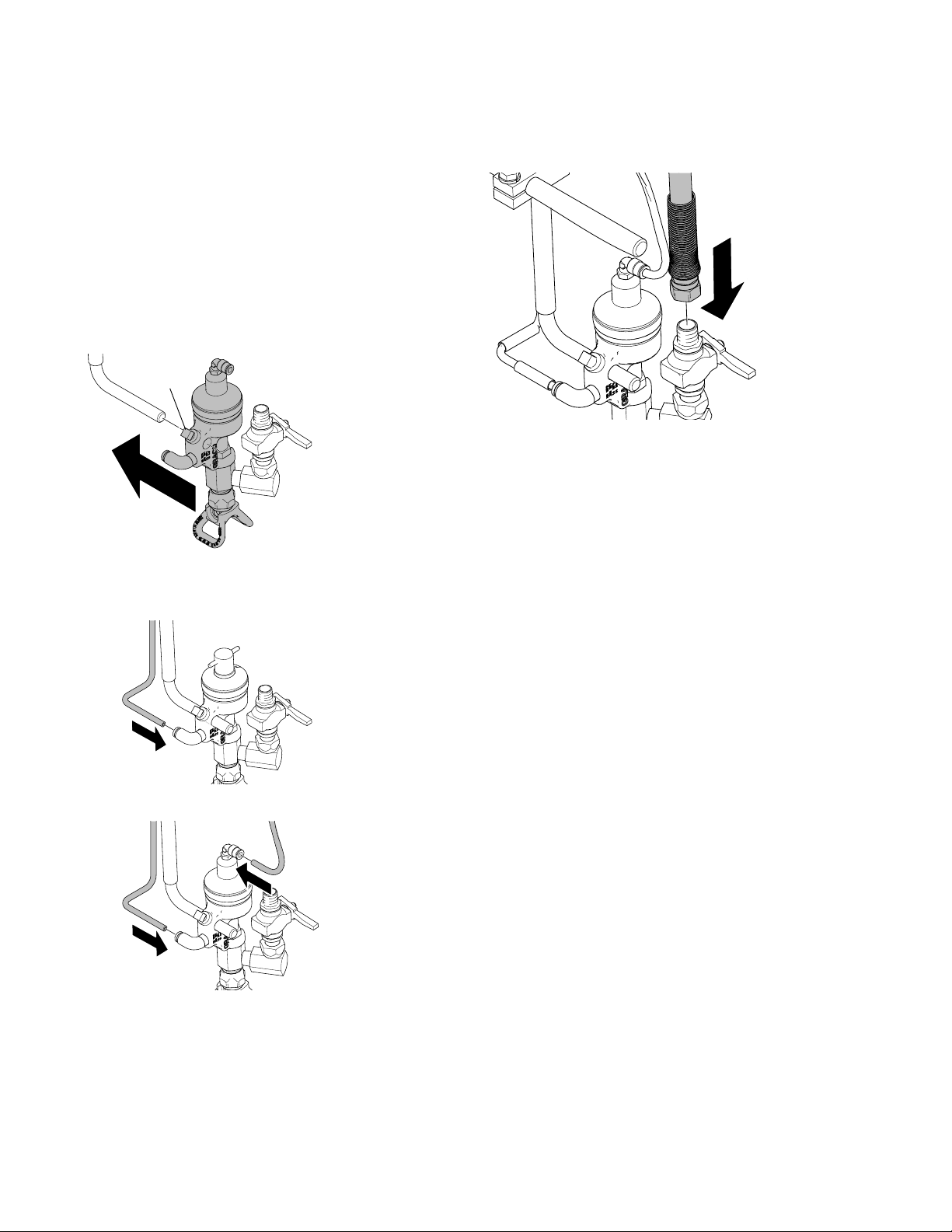
Mount Valve
Mount the valve on a 0.50 in. (12.7 mm) diameter rod on
a mounting fixture or a dispensing machine. The paint
gun has a clamping set screw (6) for mounting.
6
ti16341a
Connect the Air Lines
Connect Fluid Lines
ti16343a
Connect a grounded fluid line from the pump to the fluid
adapter of the paint spray gun. You should install a fluid
pressure regulator to control fluid pressure to the paint
spray gun. The regulator enables you to control fluid
pressure more accurately than by regulating hydraulic
pressure to the pump.
Install a fluid filter to remove particles and sediment
which may clog the tip.
Install a manual ball valve to shut off fluid flow to spray
gun.
ti16776a
Single-Acting Gun
ti16342a
Double-Acting Gun
Clean all lines and connections of dirt, burrs, etc. and
blow them out with clean air before connecting them to
the system. Install an air filter in the air supply line to
remove harmful dirt and moisture from the compressed
air.
Grounding
Proper grounding is essential to maintaining a safe system.
To reduce the risk of static sparking, ground the pump,
paint spray gun, and all other system equipment.
1. Pump: Use a ground wire and clamp.
2. Air compressors and hydraulic power supplies:
Follow manufacturer’s recommendations.
3. Air and fluid hoses connected to the pump: Use
only grounded hoses with a maximum of 500 feet
(150 m) combined hose length to ensure grounding
continuity.
4. Dispensing valve: Obtain grounding through connection to a properly grounded fluid hose and pump.
5. Fluid supply container: According to local code.
6. All solvent pails used when flushing: Ground
according to local code. Use only metal pails, which
are conductive. Do not place the pail on a non conductive surface, such as paper or cardboard, which
interrupts the grounding continuity.
4 308613E
Page 5

Operation
Operation
Adjustments
Set the actuating air to at least 75 psi (5.2 bar) and start
the pump. Set the pump speed and pressure to obtain the
desired flow rate. Always use the lowest pump speed necessary to achieve desired results.
Pressure Relief Procedure
FLUID INJECTION HAZARD
To reduce the risk of serious bodily injury, including
fluid injection, splashing in the eyes or on the skin, or
injury from moving parts, always follow this procedure
whenever you shut off the pump, when checking or
servicing any part of the dispensing system, when
installing, cleaning, or changing part of the valve and
whenever you stop dispensing.
Application Data
1. Shut off the power to the pump.
2. Close the bleed-type master air valve (required with
air-powered pumps).
3. Actuate the dispensing valve to relieve pressure.
4. Open the pump drain valve (required in your system) to
help relieve fluid pressure in the displacement pump.
Actuating the dispensing valve to relieve pressure may
not be sufficient. Have a container ready to catch the
drainage.
5. Leave the drain valve(s) open until you are ready to
dispense again.
If you suspect that the dispensing valve or hose is completely clogged, or that pressure has not been fully relieved
after following the steps above, very slowly loosen the
hose end coupling and relieve pressure gradually, then
completely loosen. Then clear the valve or hose.
APPLICATION
RECOMMENDATIONS*
3
(5)
Paint Tip Size
For a 4 inch (101 mm)
wide line
For a 6 inch (152 mm)
wide line
For a 12 inch (304 mm)
wide line
Operating Pressure
psi (bar)
Paint S ystem
* Coverage may vary depending on paint used.
433
LL5333
539
LL5439
643 649
1500-2000
(102)
4
(6)
433
LL5333
539
LL5439
1500-2000
(102)
TRAVEL SPEED IN MILES PER HOUR (KPH)
Based on 15 mils (.381 mm) wet paint
5
(8)
439 439 443
543
LL5443
1500-2000
(102)
6
(10)
549 559 561 565
1500-2000
(102)
7
(11)
LL5343
1500-2000
(102)
8
(12)
443
LL5343
1500-2000
(102)
9
(14)
445 449 453 457
1500-2000
(102)
10
(16)
1500-2000
(102)
11
(18)
1500-2000
(102)
12
(19)
1500-2000
(102)
308613E 5
Page 6

Maintenance
Maintenance
Clean Dispensing Valve and System Daily
NOTICE
Be sure that the solvent you use is compatible with the
fluid being dispensed to avoid clogging the fluid passages in the valve.
An important part of the care and maintenance of your
automatic dispensing valve is proper flushing. Flush the
valve daily with a compatible solvent until all traces of
fluid are removed from the valve passages. Perform
Pressure Relief Procedure, page 5 before flushing.
Clean the outside surfaces of the valve by wiping with a
soft cloth dampened with a compatible solvent.
NOTICE
Never immerse the entire dispensing valve in solvent.
Immersing in solvent removes lubricants and can
damage packings.
Service
Needle, Seat and Packings
To clean or replace the needle, its seat or packings (16,
17, 18), proceed as follows:
1. Perform Pressure Relief Procedure, page 5.
2. Remove valve housing:
a. Remove cap and spring.
b. Loosen nut.
ti16179a
c. Pull down housing and needle assembly to
expose needle shaft.
To remove a hardened particle from the orifice, blow air
through the orifice from the front.
Oil Dispensing Valve Daily
Before each use, lubricate with a spray of oil inside the
protection tube (13) to prevent fluid buildup on these
parts. Any buildup could damage the valve packings
(16, 17, 18).
ti16355a
Double-Acting Gun
5954b
Single-Acting Gun
ti16180a
d. Slide needle through air piston to remove.
ti16192a
3. Remove RAC guard.
ti16344a
6 308613E
Page 7

Service
4. Use an open-end wrench to remove valve seat from
valve housing.
ti16345a
5. Remove gun needle from valve body.
ti16347a
6. Remove packing nut from the valve body.
8. Clean all parts.
ti16194a
9. Lubricate and install gun needle into valve body.
ti16349a
10. Install packings (16, 17, 18, 20) on gun needle.
16
18
17
20
ti16350a
11. Install packing nut and hand-tighten into valve body.
ti16346a
7. Remove packings (16, 17, 18, 20) from valve body.
16
18
17
20
ti16351a
ti16348a
308613E 7
Page 8

Service
12. Install seat valve into valve housing.
ti16352a
13. Install valve body. Tighten nut.
ti16196a
ti16193a
14. Install RAC guard.
ti16353a
Air Piston, Spring and Seal
Perform Pressure Relief Procedure, page 5. Remove
valve as explained on page 6. Remove air cylinder cap,
take out spring and pull out the piston. Clean and
inspect all parts. Check the piston o-rings (see note 1)
carefully. Lubricate all parts with a light waterproof
grease and reassemble with valve using new parts as
necessary.
Single-Acting
238377
1
Double-Acting
24G980
1
ti16999a
1
1
ti16792a
8 308613E
Page 9

Replacement Parts and Kits (Double Acting Gun 24G980)
Replacement Parts and Kits (Double Acting Gun 24G980)
24
8
9
25
11
10
12
13
15
27
(Not included)
14
4
3
26
(Not included)
16
17
18
Ref. Part Description Qty.
1 243161 GUARD, RAC 1
*2 206987 SEAT, valve 1
3 101748 PLUG, pipe, 3/8 npt 1
4 166470 HOUSING, valve 1
5 166847 HOUSING, valve 1
6 101554 SET SCREW, cup point 1
7 166848 CAP, air cylinder 1
8 16G764 SPRING, helical compression 1
9 16G169 GUIDE, spring 1
10 164741 PISTON, air 1
*11 156593 O-RING, nitrile rubber 1
*12 155685 O-RING, nitrile rubber 1
*13 191195 TUBE, protection 1
14 191174 NUT, packing 1
15 102300 NUT, 9/16-18 nf 1
6
5
23
19
20
2
18
1
ti16354a
Ref. Part Description Qty.
*16 166255 GLAND, packing 1
*17 166258 PACKING, valve 1
*18 181523 PACKING, valve 2
*19 220194 NEEDLE, gun 1
*20 167730 GASKET, copper 1
21 164737 SCREW, adjusting 1
22 164736 PIN, handle 1
23 FITTING 1
24 FITTING 1
25 C20179 O-RING 1
26 207123 UNION, swivel, 90 deg (not included)
27 24F607 VALVE, ball, 3/8 npt, e-nickel plt
(not included)
* Included in Repair Kit 238399. Order separately.
308613E 9
Page 10

Replacement Parts and Kits (Single Acting Gun 238377)
Replacement Parts and Kits (Single Acting Gun 238377)
7
21
22
8
9
11
10
13
15
28
(Not included)
26
(Not included)
Ref. Part Description Qty.
1 243161 GUARD, RAC 1
*2 206987 SEAT, valve 1
3 101748 PLUG, pipe, 3/8 npt 1
4 166470 HOUSING, valve 1
5 166847 HOUSING, valve 1
6 101554 SET SCREW, cup point 1
7 166848 CAP, air cylinder 1
8 114060 SPRING, helical compression 1
9 164740 GUIDE, spring 1
10 164741 PISTON, air 1
*11 156593 O-RING, nitrile rubber 1
*12 155685 O-RING, nitrile rubber 1
*13 191195 TUBE, protection 1
14
3
16
17
12
6
5
4
18
19
20
2
1
5953b
Ref. Part Description Qty.
14 191174 NUT, packing 1
15 102300 NUT, 9/16-18 nf 1
*16 166255 GLAND, packing 1
*17 166258 PACKING, valve 1
*18 181523 PACKING, valve 2
*19 220194 NEEDLE, gun 1
*20 167730 GASKET, copper 1
21 164737 SCREW, adjusting 1
22 164736 PIN, handle 1
26 207123 UNION, swivel, 90 deg (not included)
28 238694 VALVE, ball (not included)
* Included in Repair Kit 238399. Order separately.
10 308613E
Page 11

Troubleshooting
Troubleshooting
Problem Cause Solution
Uneven spray pattern Fluid pressure too low Increased pressure to pump, or adjust
fluid pressure regulator
Spray gun will not stop spraying Fluid pressure too high Reduce pressure to pump, or adjust
fluid pressure regulator
Fluid needle binding Clean, repair
Piston packing binding Repair
Obstructed or worn needle seat Clean or replace
Spray gun will not spray Pump not operating Refer to separate pump manual
Fluid line clogged Clear
Fluid valve closed Open
Clogged orifice or needle seat Clean
No trigger or actuator air pressure Check, clean air lines
Worn or dry piston packings Replace
Technical Data
Single Acting Paint Gun
238377
Maximum working pressure 3000 psi (210 bar)
Operating pressure of air actuated trigger:
Minimum
Maximum
Fluid connections two 3/8 npt(f) ports
Air connection 1/4 npt(f) air inlet
Wetted parts 303 & 416 Series Stainless Steel, Tungsten Carbide, Copper,
Operating temperature 32° - 120° F
Sound pressure level 84.6 dB
Sound power level 90.9 dB
50 psi (3 bar)
200 psi (12 bar)
Acetal Homopolymer, Leather
(0° - 49° C)
Double Acting Paint Gun
24G980
75 psi (5)
200 psi (12)
*Measurements at 2900 psi (200 bar) per ISO 3744
308613E 11
Page 12

Graco Standard Warranty
Graco warrants all equipment referenced in this document which is manufactured by Graco and bearing its name to be free from defects in
material and workmanship on the date of sale to the original purchaser for use. With the exception of any special, extended, or limited warranty
published by Graco, Graco will, for a period of twelve months from the date of sale, repair or replace any part of the equipment determined by
Graco to be defective. This warranty applies only when the equipment is installed, operated and maintained in accordance with Graco’s written
recommendations.
This warranty does not cover, and Graco shall not be liable for general wear and tear, or any malfunction, damage or wear caused by faulty
installation, misapplication, abrasion, corrosion, inadequate or improper maintenance, negligence, accident, tampering, or substitution of
non-Graco component parts. Nor shall Graco be liable for malfunction, damage or wear caused by the incompatibility of Graco equipment with
structures, accessories, equipment or materials not supplied by Graco, or the improper design, manufacture, installation, operation or
maintenance of structures, accessories, equipment or materials not supplied by Graco.
This warranty is conditioned upon the prepaid return of the equipment claimed to be defective to an authorized Graco distributor for verification of
the claimed defect. If the claimed defect is verified, Graco will repair or replace free of charge any defective parts. The equipment will be returned
to the original purchaser transportation prepaid. If inspection of the equipment does not disclose any defect in material or workmanship, repairs will
be made at a reasonable charge, which charges may include the costs of parts, labor, and transportation.
THIS WARRANTY IS EXCLUSIVE, AND IS IN LIEU OF ANY OTHER WARRANTIES, EXPRESS OR IMPLIED, INCLUDING BUT NOT LIMITED
TO WARRANTY OF MERCHANTABILITY OR WARRANTY OF FITNESS FOR A PARTICULAR PURPOSE.
Graco’s sole obligation and buyer’s sole remedy for any breach of warranty shall be as set forth above. The buyer agrees that no other remedy
(including, but not limited to, incidental or consequential damages for lost profits, lost sales, injury to person or property, or any other incidental or
consequential loss) shall be available. Any action for breach of warranty must be brought within two (2) years of the date of sale.
GRACO MAKES NO WARRANTY, AND DISCLAIMS ALL IMPLIED WARRANTIES OF MERCHANTABILITY AND FITNESS FOR A
PARTICULAR PURPOSE, IN CONNECTION WITH ACCESSORIES, EQUIPMENT, MATERIALS OR COMPONENTS SOLD BUT NOT
MANUFACTURED BY GRACO. These items sold, but not manufactured by Graco (such as electric motors, switches, hose, etc.), are subject to
the warranty, if any, of their manufacturer. Graco will provide purchaser with reasonable assistance in making any claim for breach of these
warranties.
In no event will Graco be liable for indirect, incidental, special or consequential damages resulting from Graco supplying equipment hereunder, or
the furnishing, performance, or use of any products or other goods sold hereto, whether due to a breach of contract, breach of warranty, the
negligence of Graco, or otherwise.
FOR GRACO CANADA CUSTOMERS
The Parties acknowledge that they have required that the present document, as well as all documents, notices and legal proceedings entered into,
given or instituted pursuant hereto or relating directly or indirectly hereto, be drawn up in English. Les parties reconnaissent avoir convenu que la
rédaction du présente document sera en Anglais, ainsi que tous documents, avis et procédures judiciaires exécutés, donnés ou intentés, à la suite
de ou en rapport, directement ou indirectement, avec les procédures concernées.
Graco Information
For the latest information about Graco products, visit www.graco.com.
TO PLACE AN ORDER, contact your Graco distributor or call 1-800-690-2894 to identify the nearest distributor.
All written and visual data contained in this document reflects the latest product information available at the time of publication.
Graco reserves the right to make changes at any time without notice.
Original instructions. This manual contains English. MM 308613
Graco Headquarters: Minneapolis
International Offices: Belgium, China, Japan, Korea
GRACO INC. P.O. BOX 1441 MINNEAPOLIS, MN 55440-1441
Copyright 2010, Graco Inc. is registered to ISO 9001
www.graco.com
Revised 02/2011
 Loading...