

Page 1
INSTRUCTIONS-PARTS
LIST
308–626
This
manual contains important
warnings and information.
READ AND KEEP FOR REFERENCE.
INSTRUCTIONS
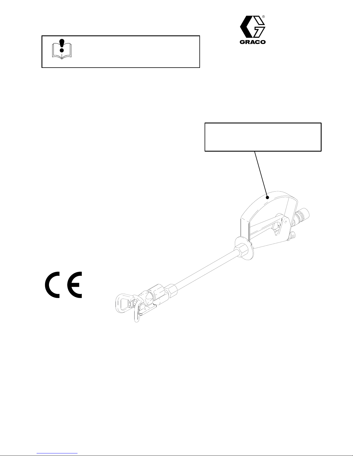
HYDRA-SPRAY
POLE GUN
3000 psi (210 bar) Maximum Working Pressure
Model 238–311, Series A
1
foot (300 mm) length
Model 238–312, Series A
2
feet (600 mm) length
Model 238–313, Series A
3
feet (910 mm) length
Model 238–314, Series A
4
feet (1.2 m) length
Supercedes Rev. A
WARNING
KEEP CLEAR OF NOZZLE
READ INSTRUCTION MANUAL CAREFULLY
- HIGH PRESSURE
Rev. B
Model 238–316, Series A
6
feet (1.8 m) length
Model 238–318, Series A
8
feet (2.4 m) length
GRACO INC. P.O. BOX 1441
MINNEAPOLIS, MN
Graco
Inc. is registered to I.S. EN ISO 9001
55440–1441
Page 2
Table
of Contents
Symbols 2.
Installation 6
Required
Electrical
Operation 7
Pressure
How
Startup 8
How
How
Lubrication 8
How
How
. . . . . . . . . . . . . . . . . . . . . . . . . . . . . . . . . . . . .
. . . . . . . . . . . . . . . . . . . . . . . . . . . . . . . . . . .
Accessories6. . . . . . . . . . . . . . . . . . . . . . . .
Grounding6. . . . . . . . . . . . . . . . . . . . . . . . .
. . . . . . . . . . . . . . . . . . . . . . . . . . . . . . . . . . . . .
Relief Procedure7. . . . . . . . . . . . . . . . . . . .
to Use the Safety Knob7. . . . . . . . . . . . . . . . . .
. . . . . . . . . . . . . . . . . . . . . . . . . . . . . . . . . . . . .
to Adjust the Spray Pattern8. . . . . . . . . . . . . . .
to Adjust the T
. . . . . . . . . . . . . . . . . . . . . . . . . . . . . . . . .
to Clear or Clean a Clogged Spray T
to Flush the Gun9. . . . . . . . . . . . . . . . . . . . . . . .
rigger Tension 8.
. . . . . . . . . . . .
ip 9.
. . . .
Symbols
Warning Symbol
WARNING
Service 10
Parts 14
Technical
Graco
The
. . . . . . . . . . . . . . . . . . . . . . . . . . . . . . . . . . . . . .
Troubleshooting 10
Adjust
the Needle
Packing,
Graco W
Seal, & Needle Replacement
. . . . . . . . . . . . . . . . . . . . . . . . . . . . . . . . . . . . . . . .
Data
Phone Number
. . . . . . . . . . . . . . . . . . . . . . . . . . . .
. . . . . . . . . . . . . . . . . . . . . . . . .
. . . . . . .
. . . . . . . . . . . . . . . . . . . . . . . . . . . . . .
. . . . . . . . . . . . . . . . . . . . . . .
arranty and Disclaimers
. . . . . . . .
10.
12.
16.
16.
16.
Caution Symbol
CAUTION
This
symbol alerts you to the possibility of serious
injury or death if you do not follow the instructions.
This
symbol alerts you to the possibility of damage to
or destruction of equipment if you do not follow the
instructions.
WARNING
HAZARD OF USING FLUIDS CONT
Never use 1,1,1-trichloroethane, methylene chloride, other halogenated hydrocarbon solvents or fluids contain
ing such solvents in this equipment. Such use could result in a serious chemical reaction, with the possibility of
explosion, which could cause death, serious injury and/or substantial property damage.
Consult your fluid suppliers to ensure that the fluids being used are compatible with aluminum and zinc parts.
AINING HALOGENA
TED HYDROCARBONS
WARNING
RECOIL HAZARD
Due
to the high pressure fluid emitted, a strong recoil action may occur when you trigger this gun. If
you are unprepared, your hand could be forced back toward your body or you could lose your balance
and fall, resulting in serious injury
.
-
2
308–626
Page 3

Notes
308–626
3
Page 4
WARNING
INJECTION HAZARD
Spray
from the spray gun, hose leaks or ruptured components can inject fluid into your body and
cause extremely serious injury
skin can also cause can also cause serious injury
D
Fluid injected into the skin might look like just a cut, but it is a serious injury. Get immediate medi
cal attention.
D
Do not point the spray gun at anyone or any part of the body
D
Do not put hand or fingers over the spray tip.
D
Do not stop or deflect fluid leaks with your hand, body
D
Do not “blow back” fluid; this is not an air spray system.
D
Always have the tip guard and the trigger guard on the spray gun (if so equipped)
when spraying.
D
Check the spray gun dif
D
Be sure the spray gun safety knob operates before operating the gun.
, including the need for amputation. Splashing fluid in the eyes or on the
.
.
, glove or rag.
fuser (if so equipped) operation weekly
. Refer to the gun manual.
-
D
Lock the spray gun safety knob when you stop spraying.
D
Follow the
stop spraying, check, clean or service any system equipment, or install or change spray tips.
D T
ighten all fluid connections before each use.
D
Check the hoses, tubes and couplings daily
nently coupled hoses cannot be repaired.
D
Handle and route hoses and tubes carefully. Keep hoses and tubes away from moving parts and
hot surfaces. Do not use the hoses to pull equipment. Do not expose Graco hoses to temperatures
above 180
Pressure Relief Procedure
_F (82_
C) or below –40
_F (–40_C).
on page 7 when you are instructed to relieve pressure,
. Replace worn or damaged parts immediately
. Perma
TOXIC FLUID HAZARD
Hazardous
splashed in the eyes or on the skin or if the fumes are inhaled.
D
Know the specific hazards of the fluid you are using.
D
Store hazardous fluid in an approved container
state and national guidelines.
D
Dress appropriately for your application. W
personal respirator
fluids or toxic fumes can cause a serious injury or death if the fluid is swallowed or
. Dispose hazardous fluid according to all local,
ear protective eyewear
, gloves and clothing.
, noise protection for the ears, a
-
4
308–626
Page 5
WARNING
FIRE AND EXPLOSION HAZARD
INSTRUCTIONS
Improper
result in fire or explosion and serious injury
D
D
D
D
D
D
D
D
D
grounding, poor air ventilation, open flames, or sparks can cause a hazardous condition and
.
Ground the equipment and the object being sprayed. See
Provide fresh air ventilation to avoid the buildup of flammable fumes from solvent or the fluid being
sprayed.
Extinguish all the open flames or pilot lights in the spray area.
Electrically disconnect all the equipment in the spray area.
Keep the spray area free of debris, including solvent, rags, and gasoline.
Do not turn on or of
Do not smoke in the spray area.
Do not operate a gasoline engine in the spray area.
If there is any static sparking while using the equipment,
correct the problem.
f any light switch in the spray area while operating or if fumes are present.
Electrical Grounding
stop spraying immediately
on page 6.
. Identify and
EQUIPMENT MISUSE HAZARD
Equipment
in serious injury
misuse can cause the equipment to rupture, malfunction, or start unexpectedly and result
.
D
This equipment is for professional use only
D
Read all instruction manuals, tags, and labels before operating the equipment.
D
Use the equipment only for its intended purpose. If you are uncertain about the usage, call your
distributor.
D
Do not alter or modify this equipment. Use only genuine Graco parts and accessories.
D
Check the equipment daily
D
Do not exceed the maximum working pressure of the lowest rated system component. This equip
ment has a
D
Route the hoses away from the traffic areas, sharp edges, moving parts, and hot surfaces. Do not
expose Graco hoses to temperatures above 160
D
Do not use the hoses to pull the equipment.
D
Use fluids or solvents that are compatible with the equipment wetted parts. See the
Data
section of all the equipment manuals. Read the fluid and solvent manufacturer’s warnings.
D
Fluid hoses must have spring guards on both ends to protect them from rupture caused by kinks or
bends near the couplings.
D
Comply with all applicable local, state and national fire, electrical and other safety regulations.
3000 psi (207 bar) maximum working pressure.
. Repair or replace worn or damaged parts immediately
.
_F (65_
C) or below –40
.
_F (–40_C).
Technical
-
D Wear hearing protection when operating this equipment.
308–626
5
Page 6

Installation
Installation
NOTE:
reference numbers on the figures and parts drawing.
1.
2.
Numbers in parentheses in the text refer to
Connect a grounded fluid hose to the gun fluid
inlet.
Without the spray tip installed, start the pump or
sprayer and flush and prime it according to the
pump or sprayer instructions.
WARNING
INJECTION HAZARD
T
o reduce the risk of a serious injury
always follow the
cedure on page 7 whenever you are
instructed to relieve the pressure.
Pressure Relief Pro
,
Required Accessories
WARNING
INJECTION
Y
our spray system must have a bleedtype master air valve and a fluid drain
valve. These two accessories help re
duce the risk of serious injury
tion, splashing in the eyes or on the skin, or injury
from moving parts, if you are adjusting or repairing
the pump or gun.
1. The
-
2. The
bleed-type master air valve
pumps only) relieves air trapped between this
valve and the pump after the air regulator is shut
off. T
rapped air can cause the pump to cycle
unexpectedly.
fluid drain valve
sure in the displacement pump, hose and gun;
triggering the gun to relieve pressure may not be
sufficient.
HAZARD
-
, including fluid injec
(air-powered
assists in relieving fluid pres
-
-
3.
Relieve the pressure.
4.
Insert SwirchTip. Guide seat into retaining nut and
turn until it fits cylinder
down. Screw nut snugly onto gun, holding orange
guard in desired direction. T
with a wrench.Cylinder handle must be in full spray
position. Make sure switch is inserted completely
before operating. Replace gasket and seat when
ever a SwitchT
5.
Strain the fluid you are spraying if it contains
particles which clog the spray tip.
ip wears out. See Fig. 1.
. Drop in gasket and press
ighten retaining nut
"
Electrical Grounding
WARNING
FIRE
AND EXPLOSION HAZARD
T
o reduce the risk of static sparking,
which can cause a fire or explosion and
result in serious injury
shock, and property damage, always
-
D
Read and follow the warnings in FIRE and
EXPLOSION HAZARD on page 5.
D Provide
the
D
Have a trained and qualified person perform all
electrical wiring.
D
Comply with all applicable local, state and
national fire, electrical and other safety
regulations.
1.
Provide electrical grounding for the
sprayer
follow these precautions.
electrical grounding continuity
entire spray system as instructed below
as instructed in its separate manual.
, including electric
throughout
.
pump or
t
!
Fig. 1
6
308–626
2.
Provide electrical grounding for the
sor or hydraulic power supply
local code and the manufacturer’s recommenda
tions.
air compres
according to the
Continued on page 7.
-
-
Page 7

Installation
Electrical Grounding contrinued from page 6.
3.
Use only electrically conductive
maximum of 500 feet (150 m) combined hose
length to ensure grounding continuity
4.
Obtain electrical grounding continuity for the
gun
by connecting it to a properly grounding fluid
hose and pump or sprayer
5.
Provide electrical grounding for these components
according to the local code: the
fluid hoses
.
.
fluid supply
Operation
Pressure Relief Procedure
WARNING
INJECTION
T
o reduce the risk of serious injury
cluding fluid injection, splashing in the
eyes or on skin, or injury from moving
parts, always follow this procedure whenever the
spray equipment is shut of
icing any part of spray system, when installing,
cleaning or changing spray tips and whenever you
stop spraying.
HAZARD
, in
f, when checking or serv
with a
spray
-
-
container
the solvent pails used when flushing.
metal pails, which are conductive. Do not place the
pail on a non-conductive surface, such as paper or
cardboard, which interrupts the grounding continu
ity.
6. To maintain grounding continuity when flush-
ing or relieving pressure, always hold a metal
part of the gun firmly to the side of a
metal pail, then trigger the gun.
, the
object being sprayed,
and
all of
Use only
grounded
WARNING
INJECTION HAZARD
The wallet-sized warning card provided
with this gun should be kept with the op
erator at all times. The card contains
important treatment information should a fluid injec
tion injury occur
no charge from Graco, Inc.
How to Use the Safety Knob
. Additional cards are available at
-
-
-
1.
Lock the gun safety knob.
2.
Shut of
any air bleed valves in the system.
3.
Unlock the gun safety knob.
4.
Hold a metal part of the gun firmly to the side of a
grounded
gun to relieve pressure.
5.
Lock the gun safety knob.
6.
Open the pump drain valve to help relieve fluid
pressure in the pump, hose and gun. T
the gun to relieve pressure may not be suf
Have a container ready to catch the drainage.
7.
Leave the drain valve open until you are ready to
spray again.
If you suspect that the spray tip or hose is completely
clogged or that pressure has not been fully relieved
after following the steps above, V
loosen the tip guard retaining nut or hose end coupling
and relieve pressure gradually
Now clear the tip or hose obstruction.
f the power supply to the pump and open
metal waste container
, and trigger the
riggering
ficient.
ER
Y SLOWL
, then loosen completely
Y
To
lock the safety knob (A), turn the knob fully clock
wise; this locks the needle in the forward position. T
unlock the safety knob, turn the knob fully counter
clockwise. See Fig. 2.
Fig. 2
.
o
-
A
04884
308–626
7
Page 8

Operation
WARNING
INJECTION HAZARD
T
o reduce the risk of a serious injury
always follow the
cedure on page 7 whenever you are
instructed to relieve the pressure.
Pressure Relief Pro
WARNING
INJECTION HAZARD
T
o reduce the risk of a fluid injection
injury
, do not operate the gun with the tip
guard or trigger guard removed.
Startup
1.
Start the pump. Adjust the fluid pressure so the
spray is completely atomized. Always use the
lowest pressure necessary to get the desired
results. Higher pressure may not improve the
spray pattern and will cause premature tip and
pump wear
.
How to Adjust the Spray Pattern
1. Relieve
,
-
2.
Loosen the tip guard retaining nut (B).
3. T
horizontal pattern and vertically (A) for a vertical
pattern. T
Fig. 3.
4.
The spray tip orifice size and spray angle deter
mines the coverage and size of the pattern. When
more coverage is needed, use a larger spray tip
rather than increasing the fluid pressure.
the pressure.
urn the tip guard/tip groove horizontally(C) for a
ighten the tip guard retaining nut. See
-
CAUTION
The openings in the tip guard are designed to
reduce paint buildup on the guard while spraying.
Any damage to the sharp edges of the openings
causes paint to collect at that area. T
aging the tip guard, do not hang the gun by the tip
guard.
How to Adjust the Trigger Tension
o avoid dam
-
2.
If adjusting the pressure does not give a good
spray pattern, try another size tip. Relieve the
pressure before changing a spray tip.
3.
Use a full-open, full-close trigger action. Hold the
gun about 14 inches (350 mm) from and at right
angles to the work surface. Don’t swing the gun in
an arc. Practice to find the best length and speed
of stroke.
AB
1
C
Fig. 3
D
The spray tip is shown
1
in the vertical position.
06654
Turn
the hex part of the trigger safety (B) in or out to
adjust the trigger tension. See Fig 4.
Lubrication
Oil the exposed part of the valve rod (16) and trigger
pivot (14) daily
gun, remove the tension adjusting screw (3), and pull
out the valve rod. See Fig. 6, page 7. Clean and oil the
exposed part of the valve rod all the way back to the
packing screw (20).
Fig. 4
. See Fig. 4. Whenever you clean the
Oil daily at
1
this point.
B
14
1
16
1
04884
8
308–626
Page 9

Operation
WARNING
INJECTION HAZARD
T
o reduce the risk of an injection or
splashing fluid in the eyes or on skin,
follow these precautions before remving,
cleaning or changing a spray tip or tip guard.
D
Do not hold your hand, body
the spray tip when cleaning or checking a
clogged tip.
D
Always point the gun toward the ground or into
a waste container when checking to see if the
spray tip is cleared.
D
Do not try to “blow back” paint; this is NOT an
air spray gun.
D
Follow the
7 before wiping the fluid buildup of
spray tip, before removing the tip guard or the
spray tip, and whenever you are instructed to
relieve the pressure.
Pressure Relief Procedure
How to Clear or Clean a
Clogged Spray Tip.
, or rag in front of
f the gun or
on page
CAUTION
Do not soak the entire gun in solvent. Prolonged
exposure to solvent can ruin the packings.
How to Flush the Gun.
Always
done spraying for the day and before the fluid being
sprayed can dry or set up in the gun.
flush the gun thoroughly whenever you are
WARNING
FIRE AND EXPLOSION HAZARD
T
o reduce the risk of a serious injury
from fluid injection, static sparking, or
splashing fluid in the eyes on or the skin,
follow these precautions when flushing.
D
Be sure the entire system and the flushing pails
are properly grounded. Refer to
Grounding
D
Remove the spray tip from the gun.
on page 6.
Electrical
NOTE: Clean the tip frequently during the daily opera
tion and at the end of the work day
fluid buildup from drying and clogging the spray tip.
1.
Relieve the pressure.
2. Engage the trigger safety latch.
3. Use a solventĆsoaked brush to clean the tip.
4. Rotate the RAC IV tip handle (D)180
5.
Start the pump.
6. Disengage the trigger safety latch. Trigger the
gun into a pail or onto the ground to remove clog.
7. Engage the trigger safety latch. Rotate the tip
handle to the spraying position.
8. If the tip is still clogged, lock the gun trigger
safety, shut off the sprayer and disconnect the
power source, and open the pressure drain valve
to relieve pressure. Clean the spray tip.
. This helps keep
_. See Fig. 3.
D
-
Use the lowest possible fluid pressure.
D
Maintain firm metal-to-metal contact between
the gun and pail during flushing.
D
Follow the
7 whenever you are instructed to relieve
pressure.
1.
Use a solvent that is compatible with the wetted
parts in the gun and the rest of the system, as well
as with the material being sprayed.
2.
Follow the flushing instructions for your spray
system or pump.
3.
If you are flushing with water
a rust inhibitor to protect the gun and packings
from corrosion.
4.
If necessary
passages thoroughly with a soft bristle brush.
Pressure Relief Procedure
, follow the water with
, disassemble the gun and clean all
on page
308–626
9
Page 10

Service
Troubleshooting.
Problem Solution
The gun continues to
spray after the trigger is
released.
Fluid is leaking past the
packings.
Fluid is leaking around
the swivel housing (9).
Adjust the needle. See
page 10. If necessary
disassemble and repair
the gun.
T
ighten the packing
screw (20) if it is loose.
Replace worn or dam
aged packings (15) or
the needle, as needed.
Replace the swivel. See
page NO
WARNING
INJECTION HAZARD
T
o reduce the risk of a serious injury
always follow the
cedure on page 7 whenever you are
instructed to relieve the pressure.
Pressure Relief Pro
21
TAG.
Adjust the Needle.
WARNING
,
serious injury
-
,
-
35
fluid in the eyes or on the skin. Be sure that the
needle assembly is properly adjusted, as instructed
below.
1.
Relieve the pressure. Disconnect the fluid hose.
2.
Check the free play of the trigger
(21) with a finger; it should move 1/8 to 5/16 inch
(3.2 to 7.9 mm). See Fig. 5. If not, adjust as de
scribed below
Grasp the hex (C) of the safety knob (35) with an
3.
1
1/16 inch open end wrench and unscrew the knob
assembly from the gun body
4. Squeeze the trigger to move the adjusting nut (19)
out, and then loosen the cap screw (3). See Fig. 6.
Unscrew
INJECTION
Improper needle adjustment may allow
the gun to be triggered even when the
safety knob is locked, which can result in
, including fluid injection and splashing
the adjusting nut (19) just a few turns.
HAZARD
. Lift the trigger
-
.
.
Fig. 5
04885
1
C
FREE
PLA
1/8 to 5/16 in.
(3 to 8 mm)
Y
04884
5.
Push the adjusting nut forward as far as possible.
Y
ou should feel the valve stem (28) contact the
seat (31). This indicates proper contact to stop the
flow of fluid.
6. T
urn the adjusting nut (19) in until the proper free
play is obtained. Squeeze the trigger to move the
adjusting nut out and tighten the cap screw (3).
7.
Screw on the safety knob (35).
10
308–626
Page 11

WARNING
INJECTION HAZARD
T
o reduce the risk of a serious injury
always follow the
cedure on page 7 whenever you are
instructed to relieve the pressure.
Swivel Kit
Pressure Relief Pro
Service
,
-
NOTE: Swivel
and 40.
Kit 238–310 contains items 7, 28, 31
40
34
31*{
7*{
7*{
12
16
to 20–25 ft-lb
Torque
1
(27–34 N
2
Apply anaerobic adhesive
25
1
Sm)
23{
2
28*{
Fig. 6
29
A
14
21
30
23{
22
35
3
19
6{
1
24
20
17{
15
18{
8
06655
308–626
11
Page 12

Service
WARNING
INJECTION HAZARD
T
o reduce the risk of a serious injury
always follow the
cedure on page 7 whenever you are
instructed to relieve the pressure.
Pressure Relief Pro
Packing, Seal, & Needle Replacement
NOTE: Repair
the gun. Parts included in the kit are marked with a
dagger (for example (5{), in the text and drawings.
The needle assembly is not included.
1.
Relieve the pressure. Disconnect the fluid hose.
2.
Unscrew the extension tube nut (A) from the
swivel housing (9). Remove the valve seat (31
and gaskets (7{). See Fig. 7.
3.
Unscrew access plug (10) and remove gasket (5
Remove the nozzle screw (27).
4.
5.
Unscrew the tube adapter (25) from the front of the
gun body (22) and pull the extension tube (30)
over the needle assembly
Kit 214–822 is available for repacking
.
,
{)
11.
Carefully remove the v-packings (15{) and the
glands (17{, 18{) from the back of the gun body
using a hooked pick.
-
{).
12. Clean all parts with a compatible solvent. Dry them
and
inspect for damage. Replace parts as needed.
13.
Install the screw (27) in the top of the swivel
housing (9). Install the new seal (13{), washer (6
and the spring (4). Place the new gasket (5
the access plug (10). Install the plug and torque it
to 22 to 23 ft-lb (20 to 31 N
14.
Be sure the needle assembly is the correct length.
See the DET
loosen the nut (12) and screw the valve rod (16) in
or out as needed. Tighten the nut (12).
15.
Lubricate the smooth shaft of the valve rod (16)
Insert the threaded end of the needle assembly
through the front of the gun.
16.
One at a time, slide the new male gland (18
six v-packings (15
ings facing the front of the gun body–
back of the valve rod (16). Slide the packings into
the packing cavity
(17{
) and press it gently into the packing cavity to
help seat the packings.
AIL in Fig. 6. If adjustment is needed,
{)
. Insert the new female gland
Sm).
–with the lips of the v-pack
onto the
,
{)
{) on
{) and
-
Unscrew the pivot (14) and remove the trigger (21).
6.
7.
Grasp the safety knob (35) hex with an 1
open end wrench. Unscrew it from the gun body
(22).
8. Grasp
9.
10.
the adjusting nut (19) flats
wrench and pull it out far enough to loosen the cap
screw
(3) with a 3/32 inch socket head wrench.
Unscrew the packing screw (20) with a 3/8 inch
open end wrench.
Carefully push the valve rod (16) assembly out the
front of the valve.
with an adjustable
1/16 inch
CAUTION
Handle the valve seat (31{) and valve stem (28
carefully to avoid damaging the hard carbide
portion of these parts.
{)
17. Screw
18. Install
19.
20.
21. Slide
22. T
23.
the packing screw (20) loosely into the cavity
the trigger (21) and pivot (14).
Place a new washer (6{) on the valve rod and
thread the adjusting nut (19) onto it. Hold the
adjusting nut with an adjustable wrench. Thread
the cap screw (3) a few turns into the nut.
Place a new gasket (23{) on each side of the front
of the trigger guard (24). Screw the tube adapter
(25) into the front of the valve. T
to 20 to 25 ft-lb (27 to 34 N
the extension tube (30) over the needle assem
bly
and
screw it onto the tube adapter (25). Screw the
tube
nut (A) onto the swivel housing (9).
ighten the packing screw (20) just enough to stop
leakage; over-tightening results in leaking.
Before using the gun, follow the procedure for
Adjust the Needle
, page 10.
orque the adapter
Sm).
.
-
12
308–626
Page 13

34
40
Service
7*{
31*{
7*{
16
Torque
1
2
to 20–25 ft-lb
(27–34 N
Apply anaerobic adhesive
Sm)
23{
25
1
NEEDLE
ASSEMBL
28*{
Y DET
29
AIL
30
A
21
14
8.84
in.
20.84 in.
32.84 in.
44.84 in.(1138.94 mm)
68.91 in.
92.91 in.
(224.54 mm)
(529.34 mm)
(834.24 mm)
(1750.21 mm)
(2359.81 mm)
12
23{
(Model 238–31
(Model 238–312)
(Model 238–313)
(Model 238–314)
(Model 238–316)
(Model 238–318)
22
2
35
3
19
6{
1
24
20
17{
15
18{
8
06655
1)
28 29 12 16
Fig.
7
308–626
04887
13
Page 14

34
40
Parts
7*{
31*{
7*{
to 20–25 ft-lb
Torque
1
(27–34 N
2
Apply anaerobic adhesive
23{
25
1
Sm)
28*{
29
A
14
21
30
23{
12
22
16
24aY
2
35
3
19
6{
1
24
20
17{
15
18{
8
06655
14
308–626
Page 15

Parts
Use Only Genuine Graco Parts and Accessories
Model 238–311, Series A
1
foot (300 mm) length
Includes items 1 to 39 as indicated.
Model 238–312, Series A
2
feet (600 mm) length
Includes items 1 to 39 as indicated.
Model 238–313, Series A
3
feet (910 mm) length
Includes items 1 to 39 as indicated.
Ref
No.
1 110–037 SCREW
3 104–301
7{ 160–671 GASKET
8 162–453
12 162–623 NUT
14 165–086 SCREW
15{ 165–672 V-P
16 165–673
17{ 165–674
18{ 165–675
19n 165–676 NUT
20 165–677 SCREW
21 190–654
22 165–679 BODY
23{ 168–845 GASKET
24 224–707
24aY 170–239 . W
25 168–847
28{ 218–903
29
Part No.
205–132
205–034
205–134
237–773
237–774
237–775
Description Qty
, rh head machine
#10-24 x 1/2
CAP SCREW
#5-40 x 5/8”
NIPPLE, hex; 1/4 npsm x 1/4 npt,
1-3/16” long
, lock
ACKING;
ROD, valve
GLAND, female
GLAND, male
, adjusting
TRIGGER, valve
, valve
GUARD, trigger;
Includes item 24a
ARNING PLA
ADAPTER, tube
STEM, valve
STEM, extension
, socket head;
, copper
, handle pivot
PTFEr 6
, packing
, copper
For model 238–313
For model 238–316
For model 238–318
For model 238–31
For model 238–312
For model 238–314
TE 1
1
Model 238–314, Series A
4
feet (1.2 m) length
Includes items 1 to 39 as indicated.
Model 238–316, Series A
6
feet (1.8 m) length
Includes items 1 to 39 as indicated.
Model 238–318, Series A
8
feet (2.4 m) length
Includes items 1 to 39 as indicated.
Ref.
No.
30
1
1
2
1
31{ 218–902 SEAT
1
34 237–859
1
35 210–170
36Y 222–385
1
38Y 172–479 T
1
39Y 172–478 T
1
40 238–310 KIT
1
1
1
1
{
2
1
Y
1
1
n
1
1
1
1
1
1
Part No.
205–131
205–035
205–133
237–776
237–777
237–778
Description Qty.
TUBE, extension
For model 238–313
For model 238–316
For model 238–318
For model 238–31
For model 238–312
For model 238–314
GUARD, tip
SAFETY KNOB, trigger
CARD, warning (not shown)
AG, instruction (not shown)
AG, instruction (not shown)
Includes 7, 28 and 31
These parts are also included in Valve Packing
and Seal Repair Kit 214–822
purchased separately
Replacement Danger and W
cards are available at no cost.
Keep these spare parts on hand to reduce down
time.
, needle valve
, swivel
.
arning labels, tags and
1
, which may be
1
1
1
1
1
1
1
1
1
1
1
1
1
308–626
15
Page 16

Technical
Data
Maximum
W
Fluid Valve Orifice Size
Fluid
Fluid
Wetted
Height
Weight
Model
Model
Model
WARRANTY
Graco
the date of sale
warranty,
tive.
ommendations.
This warranty does not cover
misapplication, abrasion, corrosion, inadequate or improper maintenance, negligence, accident, tampering, or substitution of
non–Graco component parts. Nor shall Graco be liable for malfunction, damage or wear caused by the incompatibility with Graco
equipment of structures, accessories, equipment or materials not supplied by Graco, or the improper design, manufacture, instal
lation, operation or maintenance of structures, accessories, equipment or materials not supplied by Graco.
This warranty is conditioned upon the prepaid return of the equipment claimed to be defective to an authorized Graco distributor
for verification of the claim. If the claimed defect is verified, Graco will repair or replace free of charge any defective parts. The
equipment will be returned to the original purchaser transportation prepaid. If inspection of the equipment does not disclose any
defect in material or workmanship, repairs will be made at a reasonable charge, which charges may include the costs of parts,
labor and transportation.
DISCLAIMERS AND LIMITATIONS
The terms of this warranty constitute purchaser’s sole and exclusive remedy and are in lieu of any other warranties (express or
implied),
liabilities, including product liabilities, based on negligence or strict liability
tial damages or loss is expressly excluded and denied. In no case shall Graco’
Any action for breach of warranty must be brought within two (2) years of the date of sale.
EQUIPMENT NOT COVERED BY GRACO WARRANTY
Graco makes no warranty
respect to accessories, equipment, materials, or components sold but not manufactured by Graco. These items sold, but not
manufactured by Graco (such as electric motor
Graco will provide purchaser with reasonable assistance in making any claim for breach of these warranties.
Fluid
orking Pressure
Inlet
.
. . . . . . . . . . . . . . . . . . . . . . . . . . . . .
Outlet
.
. . . . . . . . . . . . . . . . . . . . . . . . . . . . . .
Parts
.
. . . . . . . . . . . . . . . . . . . . . . . .
205–129
204–979
205–130
The
warrants all equipment manufactured by it and bearing its name to be free from defects in material and workmanship on
by an authorized Graco distributor to the original purchaser for use. As purchaser’s sole remedy for breach of this
Graco will, for a period of twelve months from the date of sale, repair or replace any part of the equipment proven defec
This warranty applies only when the equipment is installed, operated and maintained in accordance with Graco’
including warranty of merchantability or warranty of fitness for a particular purpose
.
. . . . . . . . . . . .
.
. . . .
.
. . . . . . . .
Aluminum, Tungsten Carbide,
Stainless
Steel, PTFE,r Brass, Delrin
.
. . . . . . . . . . . . . . . . . . . .
.
. . . . . . . . . . . . . . . . . . . .
.
. . . . . . . . . . . . . . . . . . . .
Graco Warranty and Disclaimers
, and Graco shall not be liable for
, and disclaims all implied
3000 psi (210 bar)
0.188 in. (4.78 mm) dia.
1/4 npsm
1/4 npt
Steel, Zinc-plated
r
5 inches (127 mm)
2 lb (0.9 kg)
4 lb (1.8 kg)
6 lb (2.7 kg)
warranties of merchantability and fitness for a particular purpose
, switches, hose, etc.) are subject to the warranty
Sound
Data
Sound Pressure Level
Sound
Power Level
*
Measured while spraying waterbase paint – gravity
1.36 through a 517 tip at 3,000 psi (207 bar).
Per
ISO 3744. Sound levels experienced
due
to pole gun length.
Graco
.
. . . . . . . . . . . . . . . . .
.
. . . . . . . . . . . . . . . . . . .
Phone
78 dB(A)*
87 dB(A)*
may be lower
Number
TO
PLACE AN ORDER
utor
, or call this number to identify the distributor
closest to you:
, any malfunction, damage or wear caused by faulty installation,
. Every form of liability for direct, special or consequen
1–800–367–4023 T
s liability exceed the amount of the purchase price.
, contact your Graco distrib
oll Free
s written rec-
, and of any non–contractual
, if any
, of their manufacturer
-
, with
.
-
-
-
All information, illustrations and specifications in this document are based on the latest product information available at the time
of publication. The right is reserved to make changes at any time without notice.
Foreign Offices:
Belgium, Canada, England, Korea, Switzerland, France, Germany
Sales Offices:
GRACO INC. P.O. BOX 1441
e1996–1998
16
308–626
Graco Inc. 308–626 Rev. B March 1998 PRINTED IN U.S.A.
Atlanta, Chicago, Detroit, Los Angeles
MINNEAPOLIS, MN
http://www.graco.com
, Hong Kong, Japan
55440–1441
 Loading...