

Page 1
Instructions
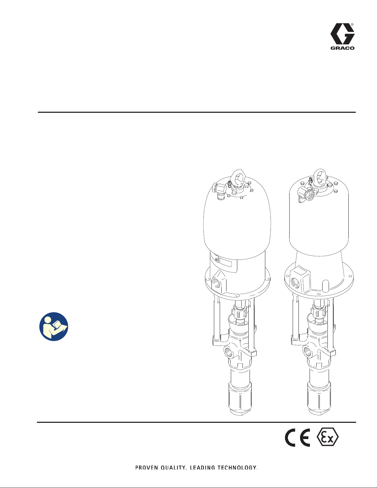
Dura-Flo® 1200 Pumps
Stainless Steel
For dispensing non-corrosive and non-abrasive oils and lubricants only. For professional
use only.
237516 Pump, Series A, 21:1 Ratio,
®
with Bulldog
2100 psi (14.5 MPa, 145 bar) Maximum Fluid Working
Pressure
100 psi (0.7 MPa, 7 bar) Maximum Air Input Working
Pressure
Air Motor
Model 237516
308360D
EN
Model 237517
237517 Pump, Series A, 13:1 Ratio,
®
with Senator
1300 psi (9 MPa, 90 bar) Maximum Fluid Working
Pressure
100 psi (0.7 MPa, 7 bar) Maximum Air Inlet Working
Pressure
Air Motor
See page 24 for model information, including maximum
working pressure and approvals.
Important Safety Instructions
Read all warnings and instructions in this
manual before using the equipment.
Save these instructions.
04143
04140
II 2 G
Page 2

Contents
Related Manuals . . . . . . . . . . . . . . . . . . . . . . . . . . . . 2
Warnings . . . . . . . . . . . . . . . . . . . . . . . . . . . . . . . . . . 3
Installation. . . . . . . . . . . . . . . . . . . . . . . . . . . . . . . . . 5
Grounding . . . . . . . . . . . . . . . . . . . . . . . . . . . . . . 5
Accessories . . . . . . . . . . . . . . . . . . . . . . . . . . . . . 5
Flush Before Using Equipment . . . . . . . . . . . . . . 6
Typical Installation . . . . . . . . . . . . . . . . . . . . . . . . 7
Operation. . . . . . . . . . . . . . . . . . . . . . . . . . . . . . . . . . 8
Pressure Relief Procedure. . . . . . . . . . . . . . . . . . 8
Flush the Equipment . . . . . . . . . . . . . . . . . . . . . . 8
Packing Nut . . . . . . . . . . . . . . . . . . . . . . . . . . . . . 9
Start and Adjust the Pump . . . . . . . . . . . . . . . . . . 9
Shutdown and Care for the Pump . . . . . . . . . . . 10
Troubleshooting . . . . . . . . . . . . . . . . . . . . . . . . . . . 11
Related Manuals
Manual in
English
311827 Dura-Flo Lowers
307049 Bulldog Air Motor
307592 Senator and Quiet Senator Air Motors
Description
Maintenance . . . . . . . . . . . . . . . . . . . . . . . . . . . . . . 12
Required Tools . . . . . . . . . . . . . . . . . . . . . . . . . . 12
Disconnect the Displacement Pump. . . . . . . . . . 12
Connect the Displacement Pump . . . . . . . . . . . . 12
Disassemble the Displacement Pump . . . . . . . . 14
Assemble the Displacement Pump. . . . . . . . . . . 16
Parts . . . . . . . . . . . . . . . . . . . . . . . . . . . . . . . . . . . . . 19
Packing Kits . . . . . . . . . . . . . . . . . . . . . . . . . . . . 21
Performance Charts . . . . . . . . . . . . . . . . . . . . . . . . 22
Model 237516 Bulldog Pump . . . . . . . . . . . . . . . 22
Model 237517 Senator Pump. . . . . . . . . . . . . . . 22
Dimensions . . . . . . . . . . . . . . . . . . . . . . . . . . . . . . . 23
Mounting Hole Layout. . . . . . . . . . . . . . . . . . . . . 23
Technical Specifications . . . . . . . . . . . . . . . . . . . . 24
California Proposition 65 . . . . . . . . . . . . . . . . . . . . 25
Graco Standard Warranty . . . . . . . . . . . . . . . . . . . 26
2 308360D
Page 3
Warnings
Warnings
The following warnings are for the setup, use, grounding, maintenance, and repair of this equipment. The
exclamation point symbol alerts you to a general warning and the hazard symbols refer to procedure-specific risks.
When these symbols appear in the body of this manual or on warning labels, refer back to these Warnings.
Product-specific hazard symbols and warnings not covered in this section may appear throughout the body of this
manual where applicable.
WARNING
EQUIPMENT MISUSE HAZARD
Misuse can cause death or serious injury.
• Do not operate the unit when fatigued or under the influence of drugs or alcohol.
• Do not exceed the maximum working pressure or temperature rating of the lowest rated system
component. See Technical Specifications in all equipment manuals.
• Use fluids and solvents that are compatible with equipment wetted parts. See Technical
Specifications in all equipment manuals. Read fluid and solvent manufacturer’s warnings. For
complete information about your material, request Safety Data Sheets (SDSs) from distributor or
retailer.
• Do not leave the work area while equipment is energized or under pressure.
• Turn off all equipment and follow the Pressure Relief Procedure when equipment is not in use.
• Check equipment daily. Repair or replace worn or damaged parts immediately with genuine
manufacturer’s replacement parts only.
• Do not alter or modify equipment. Alterations or modifications may void agency approvals and create
safety hazards.
• Make sure all equipment is rated and approved for the environment in which you are using it.
• Use equipment only for its intended purpose. Call your distributor for information.
• Route hoses and cables away from traffic areas, sharp edges, moving parts, and hot surfaces.
• Do not kink or over bend hoses or use hoses to pull equipment.
• Keep children and animals away from work area.
• Comply with all applicable safety regulations.
SKIN INJECTION HAZARD
High-pressure fluid from gun, hose leaks, or ruptured components will pierce skin. This may look like
just a cut, but it is a serious injury that can result in amputation. Get immediate surgical treatment.
• Do not spray without tip guard and trigger guard installed.
• Engage trigger lock when not spraying.
• Do not point gun at anyone or at any part of the body.
• Do not put your hand over the spray tip.
• Do not stop or deflect leaks with your hand, body, glove, or rag.
• Follow the Pressure Relief Procedure when you stop spraying and before cleaning, checking, or
servicing equipment.
• Tighten all fluid connections before operating the equipment.
• Check hoses and couplings daily. Replace worn or damaged parts immediately.
308360D 3
Page 4
Warnings
WARNING
MOVING PARTS HAZARD
Moving parts can pinch, cut or amputate fingers and other body parts.
• Keep clear of moving parts.
• Do not operate equipment with protective guards or covers removed.
• Equipment can start without warning. Before checking, moving, or servicing equipment, follow the
Pressure Relief Procedure and disconnect all power sources.
FIRE AND EXPLOSION HAZARD
Flammable fumes, such as solvent and paint fumes, in work area can ignite or explode. Paint or
solvent flowing through the equipment can cause static sparking. To help prevent fire and explosion:
• Use equipment only in well-ventilated area.
• Eliminate all ignition sources; such as pilot lights, cigarettes, portable electric lamps, and plastic drop
cloths (potential static sparking).
• Ground all equipment in the work area. See Grounding instructions.
• Never spray or flush solvent at high pressure.
• Keep work area free of debris, including solvent, rags and gasoline.
• Do not plug or unplug power cords, or turn power or light switches on or off when flammable fumes
are present.
• Use only grounded hoses.
• Hold gun firmly to side of grounded pail when triggering into pail. Do not use pail liners unless they
are anti-static or conductive.
• Stop operation immediately if static sparking occurs or you feel a shock. Do not use equipment until
you identify and correct the problem.
• Keep a working fire extinguisher in the work area.
TOXIC FLUID OR FUMES HAZARD
Toxic fluids or fumes can cause serious injury or death if splashed in the eyes or on skin, inhaled, or
swallowed.
• Read Safety Data Sheets (SDSs) to know the specific hazards of the fluids you are using.
• Store hazardous fluid in approved containers, and dispose of it according to applicable guidelines.
PERSONAL PROTECTIVE EQUIPMENT
Wear appropriate protective equipment when in the work area to help prevent serious injury, including
eye injury, hearing loss, inhalation of toxic fumes, and burns. Protective equipment includes but is not
limited to:
• Protective eyewear, and hearing protection.
• Respirators, protective clothing, and gloves as recommended by the fluid and solvent manufacturer.
4 308360D
Page 5
Installation
Installation
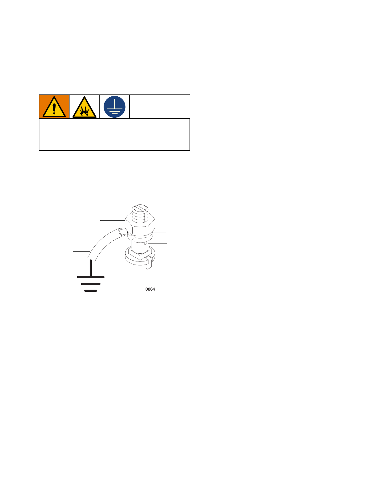
Grounding
The equipment must be grounded to reduce the risk
of static sparking. Static sparking can cause fumes to
ignite or explode. Grounding provides an escape wire
for the electric current.
Pump: use ground wire and clamp (supplied). Loosen
grounding lug locknut (LL) and washer (LW). Insert one
end of a 1.5 mm2 (12 ga) minimum ground wire end
(GW) into lug (LS) slot and tighten locknut securely.
Connect ground clamp to a true earth ground. Order
part 237569 ground wire and clamp.
LL
LW
LS
GE
Object being sprayed: follow local code.
Solvent pails used when flushing: follow local code.
Use only conductive metal pails, placed on a grounded
surface. Do not place the pail on a nonconductive
surface, such as paper or cardboard, which interrupts
grounding continuity.
To maintain grounding continuity when flushing or
relieving pressure: hold metal part of the spray
gun/dispense valve firmly to the side of a grounded
metal pail, then trigger the gun/valve.
Accessories
Install the following accessories in the order shown in
FIG. 1, page 7, using adapters as necessary. Contact
your Graco representative or Graco Technical
Assistance for assistance in designing a system to suit
your needs.
Air and Fluid Hoses
Air and fluid hoses: use only electrically conductive
hoses. Check electrical resistance of hoses. If total
resistance to ground exceeds 29 megaohms, replace
hose immediately.
Air compressor: follow manufacturer’s
recommendations.
Spray gun: ground through connection to a properly
grounded fluid hose and pump.
Fluid supply container: follow local code.
Be sure all air hoses (H) and fluid hoses (N and P) are
properly sized and pressure-rated for your system. Use
only electrically conductive hoses. Fluid hoses must
have spring guards on both ends. Use a whip hose (P)
and a swivel (R) between the main fluid hose (N) and
the gun (S) to allow freer gun movement
Mounting Accessories
Mount the pump (A) to suit the type of installation
planned. FIG. 1, page 7, illustrates a wall mount system.
See Dimensions and Mounting Hole Layout, page 23.
If you are using a floor stand, refer to its separate
manual for installation and operation instructions.
308360D 5
Page 6
Installation
Air Line
• Air line lubricator (D): provides automatic air
motor lubrication.
• Bleed-type master air valve (E): required in your
system to relieve air trapped between it and the air
motor when the valve is closed.
NOTE: Be sure the valve is easily accessible from the
pump and located downstream from the air regulator.
Trapped air can cause the pump to cycle
unexpectedly, which could result in serious injury from
splashing or moving parts.
• Air regulator (F): controls pump speed and outlet
pressure by adjusting the air pressure to the pump.
NOTE: Locate the regulator close to the pump, but
upstream from the bleed-type master air valve.
• Pump runaway valve (C): senses when the pump
is running too fast and automatically shuts off the air
to the motor. A pump which runs too fast can be
seriously damaged.
• Air manifold (G): has a 3/4 npsm(f) swivel air inlet.
It mounts to the pump support bracket, and provides
ports for connecting lines to air-powered
accessories.
• Air line filter (J): removes harmful dirt and moisture
from the compressed air supply. Also, install a drain
valve (W) at the bottom of each air line drop, to
drain off moisture.
• Second bleed-type air valve (K): isolates the air
line accessories for servicing.
Fluid Line
• Fluid filter (L): with a 60 mesh (250 micron)
stainless steel element to filter particles from the
fluid as it leaves the pump.
• Fluid drain valve (M): required in your system, to
relieve fluid pressure in the hose and gun.
• Gun (S): to dispense fluid.
NOTE: The gun shown in FIG. 1, page 7, is an airless
spray gun for light to medium viscosity fluids.
• Fluid line swivel (R): for easier gun movement.
• Suction kit (T): enables the pump to draw fluid from
a container.
NOTICE
To prevent intake valve damage, always apply PTFE
tape to the female threads of the intake valve before
connecting a suction hose or fitting to the intake.
Flush Before Using Equipment
The equipment was tested with lightweight oil, which is
left in the fluid passages to protect parts. To avoid
contaminating your fluid with oil, flush the equipment
with a compatible solvent before using the equipment.
See Flush the Equipment, page 8.
NOTE: Locate upstream from all other air line
accessories.
6 308360D
Page 7
Typical Installation
Installation
W
J
C
H
K
Main Air Line
D
E
F
G
Y
A
S
R
B
P
L
M
N
T
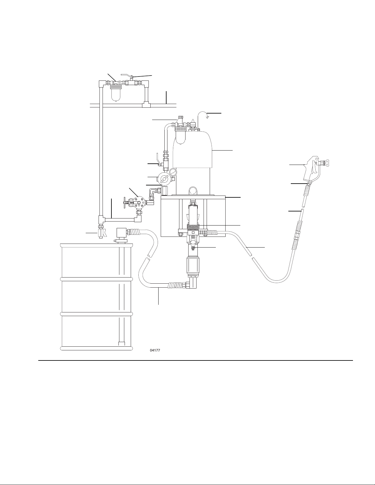
FIG. 1: Typical Installation
Key:
A Pump
B Wall bracket
C Pump runaway valve
D Air line lubricator
E Bleed-type master air valve (required for pump)
F Pump air regulator
G Air manifold
H Electrically conductive air supply hose
J Air line filter
K Bleed-type master air valve (for accessories)
308360D 7
Key:
L Fluid filter
M Fluid drain valve (required)
N Electrically conductive fluid supply hose
P Fluid whip hose
R Gun swivel
S Airless spray gun
T Suction kit
Y Ground wire and clamp (required, see
Grounding, page 5, for installation instructions)
W Air line drain valve
Page 8
Operation
Operation
Pressure Relief Procedure
Follow the Pressure Relief Procedure whenever
you see this symbol.
This equipment stays pressurized until pressure is
manually relieved. To help prevent serious injury from
pressurized fluid, such as skin injection, splashing
fluid and moving parts, follow the Pressure Relief
Procedure when you stop spraying and before
cleaning, checking, or servicing the equipment.
1. Engage trigger lock.
2. Shut off the air supply to the pump.
3. Close the bleed-type master air valve.
4. Disengage the trigger lock.
5. Hold a metal part of the gun firmly to a grounded
metal pail. Trigger the gun to relieve pressure.
Flush the Equipment
To avoid fire and explosion, always ground equipment
and waste container. To avoid static sparking and
injury from splashing, always flush at the lowest
possible pressure.
• Flush before fluid can dry in the equipment, at the
end of the day, before storing, and before repairing
equipment.
• Flush at the lowest pressure possible. Check
connectors for leaks and tighten as necessary.
• Flush with a fluid that is compatible with the fluid
being dispensed and the equipment wetted parts.
1. Perform Pressure Relief Procedure, page 8.
2. Remove spray tip from the gun.
3. Hold a metal part of the gun firmly to a grounded
metal pail.
4. Start the pump.
5. Trigger the gun until clean solvent dispenses.
6. Engage the trigger lock.
7. Open all fluid drain valves in the system, having a
waste container ready to catch drainage. Leave
drain valve(s) open until you are ready to spray
again.
8. If you suspect the spray tip or hose is clogged or
that pressure has not been fully relieved:
a. VERY SLOWLY loosen the tip guard retaining
nut or the hose end coupling to relieve pressure
gradually.
b. Loosen the nut or the coupling completely.
c. Clear the obstruction in the hose or tip.
8 308360D
6. Perform Pressure Relief Procedure, page 8.
Page 9

Operation
Packing Nut
Before starting, fill the packing nut (2) 1/3 full with Graco
Throat Seal Liquid (TSLTM) or compatible solvent.
The packing nut is torqued at the factory and is ready for
operation, If it becomes loose and there is leaking from
the throat packings:
1. Perform the Pressure Relief Procedure, page 8.
2. Torque the packing nut (2) to 136-149 N•m
(100-110 ft-lb) with the supplied wrench (110).
NOTE: Do not overtighten the packing nut.
Model 237516
Shown
Start and Adjust the Pump
1. Connect the suction kit (T) to the pump fluid inlet.
Place the tube into the fluid supply.
NOTICE
To prevent intake valve damage, always apply PTFE
tape to the female threads of the intake valve before
connecting a suction hose or fitting to the intake.
2. Close the air regulator (F).
3. Open the pump bleed-type master air valve (E).
4. Hold a metal part of the gun (S) firmly to the side of
a grounded metal pail and hold the trigger open.
5. Slowly open the regulator until the pump starts.
To reduce the risk of over-pressurizing your system,
which could cause rupture and serious injury, never
exceed the specified Maximum Air Input Pressure to
the pump (see Technical Specifications, pages
24-25).
1
Torque to
1
136-149 N•m
(100-110 ft-lb)
6. Cycle the pump slowly until all air is pushed out and
the pump and hoses are fully primed.
7. Release the gun trigger, engage the trigger safety
lock. The pump should stall against pressure.
8. If the pump fails to prime properly, open the drain
110
2
valve (M). Use the drain valve as a priming valve
until the fluid flows from the valve. Close the valve.
NOTE: When changing fluid containers with the hose
and gun already primed, open the drain valve (M) to
help prime the pump and vent air before it enters the
hose. Close the drain valve when all air is eliminated.
NOTICE
Do not allow the pump to run dry. It will quickly
accelerate to a high speed, causing damage. If your
pump is running too fast, stop it immediately and
check the fluid supply. If the container is empty and
air has been pumped into the lines, refill the container
04143
and prime the pump and the lines, or flush and leave
it filled with a compatible solvent. Eliminate all air
from the fluid system.
9. With the pump and lines primed, and with adequate
air pressure and volume supplied, the pump will
start and stop as you open and close the gun. In a
308360D 9
Page 10

Operation
circulating system, the pump will speed up or slow
down on demand, until the air supply is shut off.
10. Use the air regulator (F) to control pump speed and
fluid pressure.
NOTICE
Always use the lowest air pressure necessary to get
the desired results. Higher pressures cause
premature tip and pump wear.
Shutdown and Care for the Pump
1. Follow the Pressure Relief Procedure, page 8.
2. Follow Flush the Equipment, page 8.
NOTICE
Always flush the pump before the fluid dries on the
displacement rod and causes damage.
NOTICE
For overnight shutdown, stop the pump at the bottom
of its stroke to prevent fluid from drying on the
exposed displacement rod and damaging the throat
packings.
10 308360D
Page 11
Troubleshooting
1. Follow Pressure Relief Procedure, page 8, before
checking or repairing the pump.
Troubleshooting
To determine if the fluid hose or gun is obstructed:
1. Perform the Pressure Relief Procedure, page 8.
2. Disconnect the fluid hose and place a container at
the pump fluid outlet to catch any fluid.
3. Turn on the air just enough to start the pump. If the
pump starts when the air is turned on, the
obstruction is in the fluid hose or gun.
2. Check all possible problems and causes before
disassembling pump.
Problem Cause Solution
The pump fails to operate. The air line is restricted or the air
line is inadequate; valves are closed
or clogged.
The fluid hose or gun is obstructed;
the fluid hose ID is too small.
Fluid has dried on the displacement
rod.
Motor parts are dirty, worn, or
damaged.
The pump operates, but the output
is low on both strokes.
The air line is restricted or the air
line is inadequate; valves are closed
or clogged.
The fluid hose or gun is obstructed;
the fluid hose ID is too small.
The packings in the displacement
pump are worn.
NOTE: If you experience air motor icing, call Graco
Technical Assistance.
Clear the line; increase the air
supply. Check that the valves are
open.
Open, clear*; use a hose with a
larger ID.
Clean the rod; always stop the pump
at the bottom of its stroke; keep the
wet-cup 1/3 filled with a compatible
solvent.
Clean or repair; see the separate
motor manual.
Clear the line; increase the air
supply. Check that the valves are
open.
Open, clear*; use a hose with a
larger ID.
Replace the packings.
The pump operates, but the output
is low on the downstroke.
The pump operates, but the output
is low on the upstroke.
Erratic or accelerated pump speed. The fluid supply is exhausted. Refill the supply and prime the
308360D 11
The intake valve is held open or
worn.
The piston valve or packings are
held open or worn.
The piston valve or packings are
held open or worn.
The intake valve is held open or
worn.
Clear the valve; service.
Clear the valve; replace the
packings.
pump.
Clear the valve; replace the
packings.
Clear the valve; service.
Page 12

Maintenance
Maintenance
Required Tools
• Set of adjustable wrenches
• Large pipe wrench
• Torque wrench
• Rubber mallet
• O-ring pack
• Large vise
• Thread lubricant
• Thread sealant
Disconnect the Displacement Pump
To prevent injury from crushing or pinching, always
use at least two people when lifting, moving, or
disconnecting the pump. When disconnecting the
pump, be sure to securely brace the pump, or have
two people hold it while another person disconnects
it.
If the pump is on a cart, slowly tip the cart backward
until the handle rests on the ground, then disconnect
the displacement pump.
1. Follow Flush the Equipment, page 8.
2. Follow the Pressure Relief Procedure, page 8.
b. Hold the tie rod flats with a wrench to keep the
rods from turning. Unscrew the nuts (108) from
the tie rods (105). Carefully remove the
displacement pump (109) from the motor (101).
Connect the Displacement Pump
To prevent injury from crushing or pinching, always
use at least two people when lifting, moving, or
disconnecting the pump. When disconnecting the
pump, be sure to securely brace the pump, or have
two people hold it while another person disconnects
it.
If the pump is on a cart, slowly tip the cart backward
until the handle rests on the ground, then disconnect
the displacement pump.
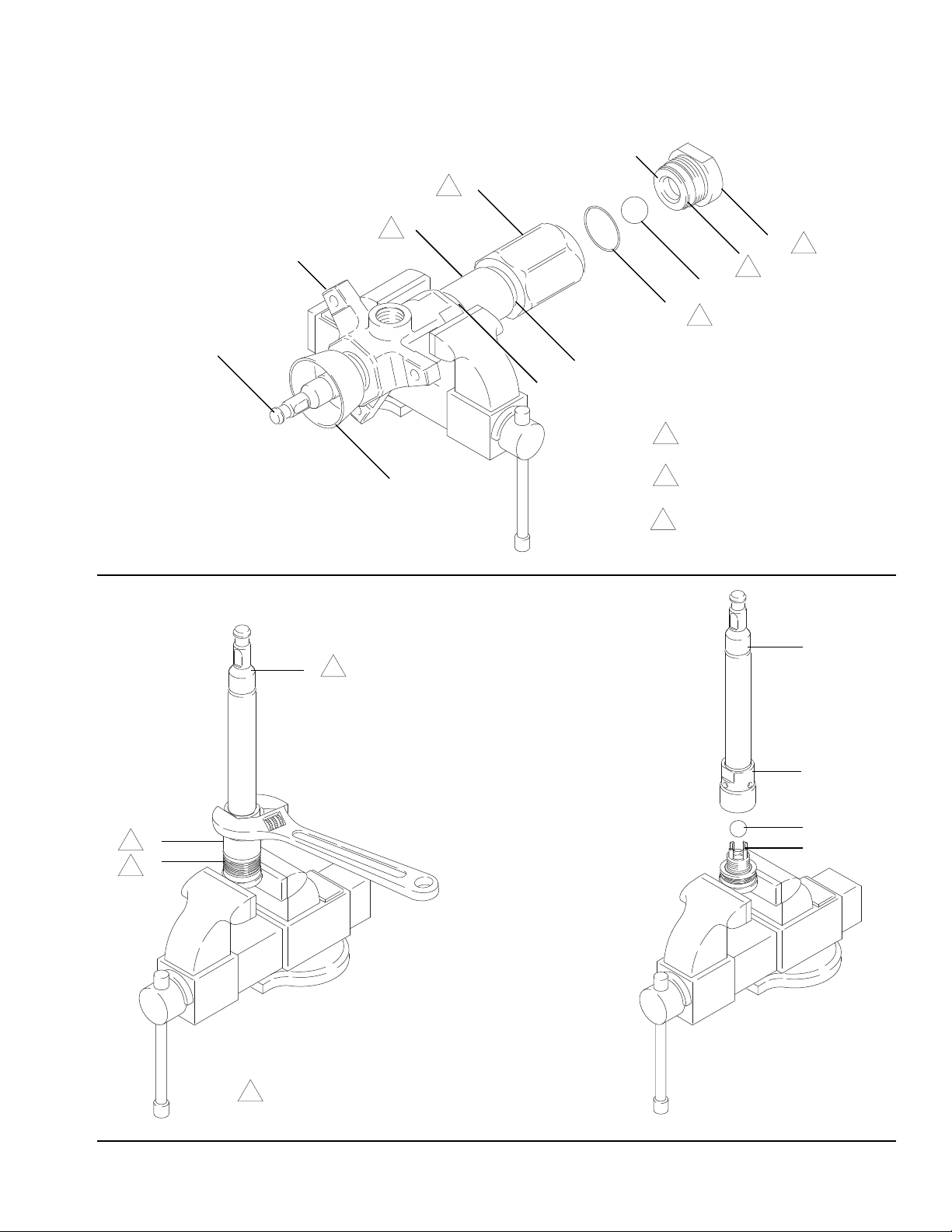
1. Make sure the coupling nut (106) and the coupling
collars (107) are in place on the displacement rod.
2. Align the pump fluid outlet (U) with the motor air inlet
(V). Position the displacement pump (109) on the tie
rods.
NOTE: Use at least two people to hold the displacement
pump while another reconnects it to the motor.
3. Screw the nuts (108) onto the tie rods (105). Torque
the nuts to 81-89 N•m (60-66 ft-lb).
3. Disconnect the air hose and fluid hose.
4. Disconnect the displacement pump (109) from the
motor (101).
NOTE: Note the relative position of the pump’s fluid
outlet (U) to the air inlet (V) of the motor. If the motor
does not require servicing, leave it attached to its
mounting.
a. Using an adjustable wrench (or hammer and
punch), unscrew the coupling nut (106) from the
motor shaft (MS). Do not lose or drop the
coupling collars.
12 308360D
4. Screw the coupling nut onto the motor shaft (MS)
loosely. Hold the motor shaft flats with a wrench to
keep it from turning. Use an adjustable wrench to
torque the coupling nut to 196–210 N•m (145–155
ft-lb).
5. Reconnect all hoses. Reconnect the ground wire if it
was disconnected. Fill the packing nut (2) 1/3 full of
TSL or compatible solvent.
6. Turn on the air supply. Run the pump slowly to
ensure proper operation.
7. Before returning the pump to production, relieve the
pressure and torque the packing nut to 136–149
N•m (100–110 ft-lb).
Page 13

Model 237516 Shown
Maintenance
V
101
Torque to 136–149 N•m
1
(100–110 ft-lb)
Torque to 196–210 N•m
2
(145–155 ft-lb)
3
Torque to 81–89 N•m
(60–66 ft-lb)
FIG. 2
MS
110
107
105
3
106
2
1
2
1
108
3
109
U
308360D 13
Page 14

Maintenance
Disassemble the Displacement Pump
When disassembling the pump, lay out all the removed
parts in sequence, to ease reassembly.
NOTE: Packing Repair Kits are available. For the best
results, use all the new parts in the kit. Kit parts are
marked with *. You can also convert the pump to
different packing materials. See Packing Kits, page 21.
1. Place the pump lengthwise in a large vise, with the
jaws on the outlet housing (7) as shown in FIG. 3,
page 15. Using the supplied wrench (110), loosen,
but do not remove, the packing nut (2).
2. Apply a pipe wrench to the flats of the intake valve
(19) from the intake housing (18). Be careful to
catch the intake ball (17) as you remove the intake
valve, so that it does not fall and suffer damage.
Remove the seal (8) from the intake valve. Inspect
the ball and the seat (BS) of the intake valve for
wear or damage.
3. Apply a pipe wrench to the hex of the valve housing
(18). The pump assembly may separate at joint A or
joint B.
NOTICE
To reduced the possibility of damage to the rod (1)
and cylinder (9), always use a rubber mallet to drive
the rod out of the cylinder. Never use a hammer to
drive out the rod,
• If the assembly separates at joint A:
a. Unscrew the valve housing (18) from the
cylinder.
b. Using a rubber mallet, drive the displacement
rod (1) and piston assembly out of the outlet
housing (7) and cylinder (9) until the piston
comes free. Pull the rod and piston from the
cylinder, being careful not to scratch the parts.
c. Unscrew the cylinder (9) from the outlet housing
(7), using a pipe wrench.
d. Remove the two seals (8) from the cylinder.
Shine a light into the cylinder (9) to inspect the
inner surface for scoring or wear.
• If the assembly separates at joint B:
a. Unscrew the cylinder (9) and valve housing (18)
from the outlet housing (7).
b. Gently pull the cylinder and valve housing
straight out of the outlet housing; the
displacement rod (1) and piston assembly will
come out with these parts.
c. Place the valve housing (18) in the vise and
unscrew the cylinder (9) from the housing, using
a pipe wrench. The displacement rod (1) and
piston assembly will remain in the cylinder.
d. Using a rubber mallet, drive the displacement
rod (1) and piston assembly out of the cylinder
(9) until the piston comes free. Pull the rod and
piston from the cylinder, being careful not to
scratch the parts.
e. Remove the two seals (8) from the cylinder.
Shine a light into the cylinder (9) to inspect the
inner surface for scoring or wear.
f. Proceed to step 6.
4. Place the flats of the piston seat housing (16) in a
vise, as shown in FIG. 4, page 15.
5. Using an adjustable wrench, unscrew the piston ball
housing (10) from the piston seat housing. Be
careful to catch the piston ball (11) as you separate
the piston seat housing and ball housing, so that it
does not fall and suffer damage.
6. Examine the displacement rod (1) for scratches or
other damage. Only if the rod needs replacement,
unscrew it from the piston ball housing (10), using
an adjustable wrench on the flats of the rod.
7. Remove the glands and v-packings (PV) from the
piston seat housing (16). Inspect the ball (11), and
the seat (PS) and guides (PG) on the housing for
wear or damage. See FIG. 5, page 18.
8. Unscrew the packing nut (2) from the outlet housing
(7). Remove the glands and v-packings (OV). See
FIG. 5, page 18.
9. Clean all parts with a compatible solvent and
inspect them for wear or damage.
e. Proceed to step 6.
14 308360D
Page 15
Maintenance
BS
18
1
9
1
7
19
3
2
17*
8*
2
FIG. 3
1
Joint A
Joint B
Torque to 325–353 N•m
1
(240–260 ft-lb).
Lubricate.
2
03794A
2
3
Torque to 190–217 N•m
(140–160 ft-lb).
1
1
1
10
11*
10
1
16
1
Torque to 386–407 N•m
1
(285–300 ft-lb).
16
03793A
FIG. 4
308360D 15
Page 16

Maintenance
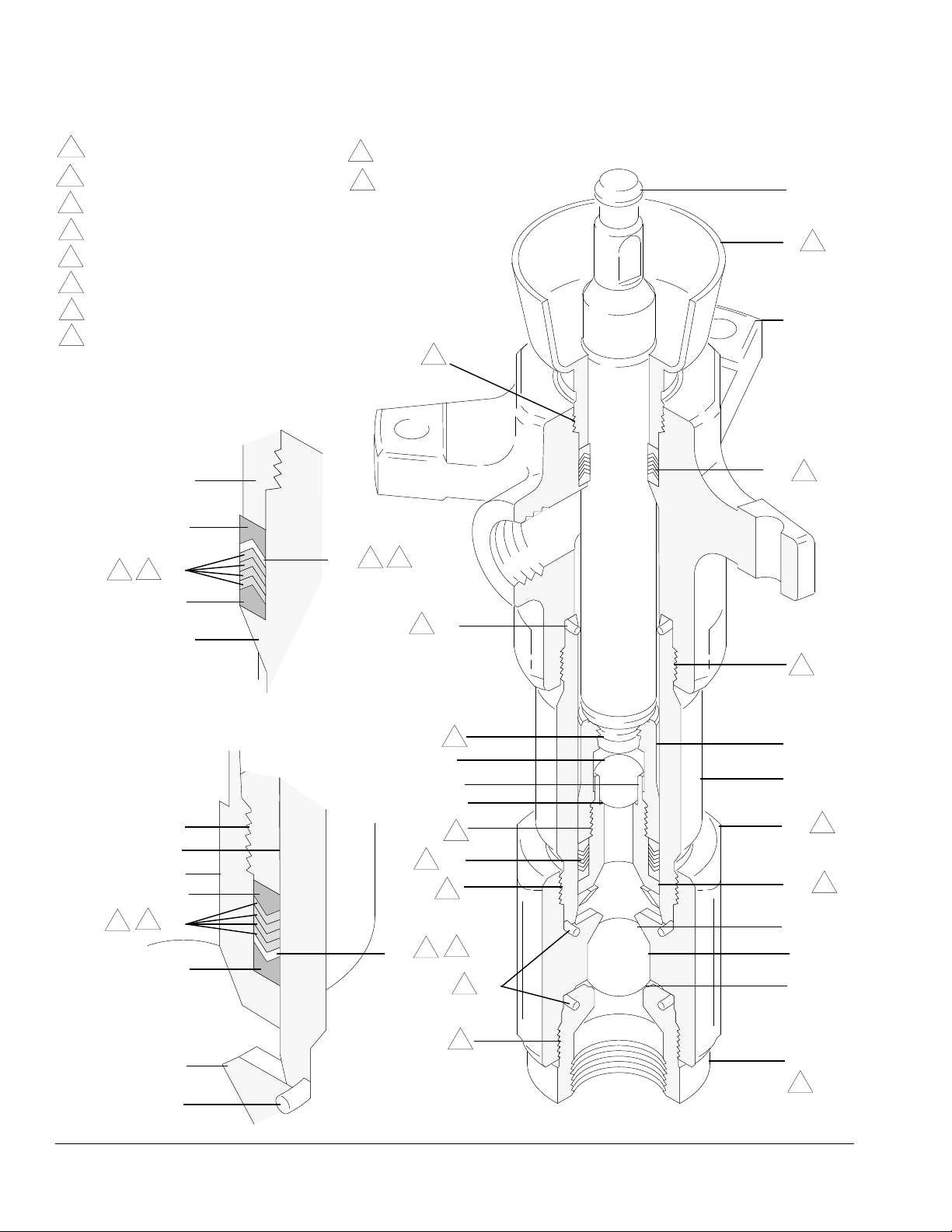
Assemble the Displacement Pump
NOTICE
All rebuild kits are supplied with anti-seize. Failure to
apply anti-seize during the reassembly process
greatly increases the chances of galling.
1. If it was necessary to remove the piston ball
housing (10) from the displacement rod (1):
a. Clean the threads of the rod and the ball
housing apply anti-seize (20*).
b. Screw the ball housing onto the rod, hand tight.
c. Place the flats of the piston ball housing in a
vise and torque the rod to 386–407 N•m (285–
300 ft-lb). See FIG. 5, page 18.
2. For standard displacement pump 237514, place
the piston packings on the piston seat housing (16)
in the following order, with the lips of the v-packings
facing up (see the Piston Packing Stack Detail in
FIG. 5, page 18):
- the female gland (15*)
- one PTFE v-packing (14*)
- four leather v-packings (12*)
- the male gland (13*)
NOTE: If your pump uses an optional packing
configuration, or you want to convert the pump to a
different packing material, see Packing Kits, page 21.
3. Place the flats of the piston seat housing (16) in a
vise.
4. Place the ball (11*) on the housing and apply
anti-seize (20*) to threads. Screw the piston ball
housing (10) onto the piston seat housing hand
tight, then torque to 386–407 N•m (285–300 ft-lb).
See FIG. 4, page 15.
NOTE: If your pump uses an optional packing
configuration, or you want to convert the pump to a
different packing material, see Packing Kits, page 21.
6. Apply anti-seize (20*) and install the packing nut (2)
loosely into the outlet housing (7).
7. Lubricate the piston packings. Slide the
displacement rod (1) and piston assembly down into
the cylinder (9).
NOTE: The cylinder is symmetrical, so either end may
face up.
8. Use a rubber mallet to drive the rod into the cylinder,
until the piston seat housing (16) is near the bottom
of the cylinder.
9. Install the seal (8*) on the top of the cylinder (9).
Lubricate the seal and apply anti seize (20*) to
threads of the cylinder.
10. Place the outlet housing (7) in a vise, as shown in
FIG. 5, page 18.
11. Slide the displacement rod (1) up into the outlet
housing, then screw the cylinder (9) into the outlet
housing hand tight.
NOTE: The threads will engage easily until the seal (8*)
contacts the sealing surface of the outlet housing. The
top of the rod will protrude from the packing nut (2).
12. Install the seal (8*) on the bottom of the cylinder (9).
Lubricate the seal and apply anti seize (20*) to
threads of the cylinder.
13. With the beveled ball stop surfaces (SS) facing
down (see FIG. 5, page 18), screw the intake
housing (18) onto the cylinder hand tight.
NOTE: The threads will engage easily until the seal
contacts the sealing surface of the intake housing.
5. For standard displacement pump 237514,
lubricate the throat packings and place them in the
outlet housing (7) in the following order with the lips
of the v-packings facing down (see the Throat
Packing Stack Detail in FIG. 5, page 18):
- the male gland (6*)
- four leather v-packings (3*)
- one PTFE v-packing (5*)
- the female gland (4*)
16 308360D
14. Install the seal (8*) on the intake valve (19).
Lubricate the seal and apply anti seize (20*) to
threads of the intake valve.
15. Place the intake ball (17*) in the intake housing (18),
then screw the intake valve into the intake housing
hand tight.
NOTE: The threads will engage easily until the seal
contacts the sealing surface of the intake housing.
Page 17

Maintenance
16. Using a pipe wrench, torque the intake housing (18)
to 325–353 N•m (240–260 ft-lb). This will torque
both cylinder joints (A and B). See FIG. 3, page 15.
17. Using a pipe wrench, torque the intake valve (19) to
190–217 N•m (140–150 ft-lb). See FIG. 3, page 15.
18. Torque the packing nut (2) to 136–149 N•m (100–
110 ft-lb).
19. Follow Connect the Displacement Pump, page
12.
308360D 17
Page 18
Maintenance
Torque to 136–149 N•m (100–110 ft-lb).
1
Torque to 325–353 N•m (240–260 ft-lb).
2
Torque to 386–407 N•m (285–300 ft-lb).
3
Lubricate.
4
Lips face up.
5
Lips face down.
6
See Throat Packing Detail at left.
7
See Piston Packing Detail at left.
8
Throat Packing Stack Detail
(Displacement Pump 237515 Shown. See
Packing Kits, page 21 for options.)
2 (Ref)
Torque to 190–217 N•m (140–160 ft-lb).
9
Apply anti-seize (123174).
10
10
OV
1
2
1
7
7
*4
*3
4
6
*6
7 (Ref)
Piston Packing Stack Detail
(Displacement Pump 237515 Shown.
See Packing Kits, page 21 for options.)
10 (Ref)
9 (Ref)
16 (Ref)
*13
*12
4
5
*15
5*
4
6
*8
4
10
3
10
*11
PG
9
PS
2
10
PV
8
10
18
16
3
SS
4
5
14*
*8
4
17*
BS
10
18 (Ref)
19
9
*8 (Ref)
FIG. 5
03634
18 308360D
Page 19

Parts
Parts
237516 Pump, Series A
21:1 Ratio, with Bulldog Air Motor
101
†105
107†
106†
102
110†
237517 Pump, Series A
13:1 Ratio, with Senator Air Motor
101
†105
102
107†
110†
106†
†108
Ref. Part Description Qty.
101 208356 AIR MOTOR, Bulldog, See 307–049 for
parts
176529 LABEL, warning
102
105† 190000 ROD, tie; 224 mm (8.82 in.) shoulder to
shoulder
106† 186925 NUT, coupling
107† 184129 COLLAR, coupling
108† 106166 NUT, hex; M16 x 2.0
109 237514 PUMP, displacement. See page 19 for
parts
110† 112887 WRENCH, spanner
Replacement safety labels, tags, and cards are available at no
cost.
† These parts are included in Connection Kit 235417. For applications
requiring stainless steel tie rods, order Connection Kit 235418.
109
†108
Ref. Part Description Qty.
101 217540 AIR MOTOR, Senator, See 307–592
1
for parts
1
3
1
2
3
1
1
176529 LABEL, warning
102
105† 190000 ROD, tie; 224 mm (8.82 in.) shoulder to
shoulder
106† 186925 NUT, coupling
107† 184129 COLLAR, coupling
108† 106166 NUT, hex; M16 x 2.0
109 237514 PUMP, displacement. See page 19 for
parts
110† 112887 WRENCH, spanner
Replacement safety labels, tags, and cards are available at no
cost.
† These parts are included in Connection Kit 235417. For applications
requiring stainless steel tie rods, order Connection Kit 235418.
109
1
1
3
1
2
3
1
1
308360D 19
Page 20

Parts
Throat Packing Stack (see
Packing Kits, page 21)
2
10
11*
7
2
Piston Packing Stack
(see Packing Kits,
page 21)
16
8*
1
18
*8
8*
17*
9
19
03630
NOTE: The parts listed on this page are common to all
displacement pumps covered in this manual. Refer to
page 21 for the different packing configurations
available.
Ref. Part Description Qty.
1 184487 ROD, displacement; stainless steel
2 236582 PACKING NUT; stainless steel
7 237186 HOUSING, outlet; stainless steel
8* 109499 SEAL; PTFE
9 184540 CYLINDER; stainless steel
10 189409 HOUSING, ball, piston; stainless steel
11* 102972 BALL, piston; stainless steel; 0.875 in.
(22.2 mm) diameter
Ref. Part Description Qty.
16 222951 HOUSING, seat, piston valve; stainless
steel with tungsten carbide seat
17* 108001 BALL, intake; stainless steel; 1.5 in.
(38.1 mm) diameter
18 189396 HOUSING, intake; stainless steel
1
19 236588 VALVE, intake; stainless steel with
1
1
22 101748 PLUG, pipe, socket hd; 3/8 npt
2
24 172477 TAG, warning (not shown)
1
25 172479 TAG, warning (not shown)
1
* Parts included in Repair Kit 237178, which may be purchased
1
separately for standard Displacement Pump 237514. See page 20.
They are also included in Optional Kits 237179, 237180, and 237713.
Replacement safety labels, tags, and cards are available at no cost.
tungsten carbide seat
20 308360D
1
1
1
1
1
1
1
Page 21

Packing Kits
Leather Packing Kit 237178, for Standard Displacement Pump 237514, Series A
Parts
Ref. Part Description Qty.
3* 184309 V-PACKING, throat; leather
4* 184179 GLAND, throat, female; stainless steel
5* 109309 V-PACKING, throat; PTFE
6* 184229 GLAND, throat, male; stainless steel
12* 184310 V-PACKING, piston; leather
13* 184230 GLAND, piston, male; stainless steel
14* 109310 V-PACKING, piston; PTFE
15* 184180 GLAND, piston, female; stainless steel
20* 123174 ANTI-SEIZE (not shown)
Throat Packings:
4
1
1
1
4
Lips Face Down
*4
*5
*3
1
1
1
*6
1
Piston Packings:
Lips Face Up
*13
*12
*15
14*
0805
0806
PTFE Packing Kit 237179, for Optional Displacement Pump 236490, Series A
Ref. Part Description Qty.
4* 184179 GLAND, throat, female; stainless steel
5* 109309 V-PACKING, throat; PTFE
6* 184229 GLAND, throat, male; stainless steel
13* 184230 GLAND, piston, male; stainless steel
14* 109310 V-PACKING, piston; PTFE
15* 184180 GLAND, piston, female; stainless steel
20* 123174 ANTI-SEIZE (not shown)
1
5
1
1
5
1
1
Throat Packings:
Lips Face Down
*4
*5
*6
Piston Packings:
Lips Face Up
*13
*14
*15
0805
0806
UHMWPE and Leather Packing Kit 237180, for Optional Displacement Pump 237515, Series A
Ref. Part Description Qty.
3* 184309 V-PACKING, throat; leather
4* 184179 GLAND, throat, female; stainless steel
5* 109259 V-PACKING, throat; UHMWPE
6* 184229 GLAND, throat, male; stainless steel
12* 184310 V-PACKING, piston; leather
13* 184230 GLAND, piston, male; stainless steel
14* 109260 V-PACKING, piston; UHMWPE
15* 184180 GLAND, piston, female; stainless steel
20* 123174 ANTI-SEIZE (not shown)
2
1
3
1
2
1
3
1
1
UHMWPE and PTFE-Packing Kit 237713 (Optional)
Ref. Part Description Qty.
3* 184309 V-PACKING, throat; leather
4* 184179 GLAND, throat, female; stainless steel
5* 109259 V-PACKING, throat; UHMWPE
6* 184229 GLAND, throat, male; stainless steel
12* 184310 V-PACKING, piston; leather
13* 184230 GLAND, piston, male; stainless steel
14* 109260 V-PACKING, piston; UHMWPE
15* 184180 GLAND, piston, female; stainless steel
20* 123174 ANTI-SEIZE (not shown)
2
1
3
1
2
1
3
1
1
Throat Packings:
Lips Face Down
*4
*5
*6
Throat Packings:
Lips Face Down
*4
*5
*3
*6
Piston Packings:
Lips Face Up
*13
*14
*15
Piston Packings:
Lips Face Up
*13
*14
*15
*12
*12
0805
0806
0805
0806
* Parts are included in Repair Kits 237178, 237179, 237180, or 237713 (purchase separately). Kits also include parts 8*, 11*, and 17*.
308360D 21
Page 22

Performance Charts
0
0
0
Performance Charts
To find Fluid Outlet Pressure (psi/bar) at a specific
fluid flow (gpm/lpm):
1. Locate desired flow along bottom of chart.
2. Follow vertical line up to intersection with selected
fluid outlet pressure curve (black). Follow left to
scale to read fluid outlet pressure.
To find Pump Air Consumption (m3/scfm) at a
specific fluid flow (gpm/lpm) and air pressure
(psi/bar):
1. Locate desired flow along bottom of chart.
2. Read vertical line up to intersection with selected air
consumption curve (gray). Follow right to scale to
read air consumption.
Key
Black Curve Fluid Outlet Pressure
Gray Curve Air Consumption
A 7 bar (100 psi) Air Pressure
B 4.9 bar (70 psi) Air Pressure
C 2.8 bar (40 psi) Air Pressure
NOTE: Recommended pump speed for continuous
operation (to shaded area) is 60 cpm.
Model 237516 Bulldog Pump
psi
bar
175
140
105
70
FLUID PRESSURE
35
gpm
lpm
12.5 50 75
A
B
C
FLUID FLOW (NUMBER 10 WEIGHT OIL)
25
7.6
cycles/min
37.5
15.2
62.5
60
A
B
C
19.0
Model 237517 Senator Pump
scfm
3
m
/min
250
7.00
200
5.60
150
4.20
100
2.80
50
1.40
22.811.43.8
psi
bar
105
12.5 50 75
A
70
cycles/min
37.5
25
60
62.5
scfm
3
m
/min
150
4.2
100
2.8
B
FLUID PRESSURE
35
C
A
B
50
1.4
C
gpm
lpm
7.6
FLUID FLOW (NUMBER 10 WEIGHT OIL)
15.2
19.0
22.811.43.8
22 308360D
Page 23

Dimensions
G
Performance Charts
Mounting Hole Layout
94.28 mm
(3.712 in.)
101.6 mm
(4.0 in.)
94.28 mm
(3.712 in.)
C
50.8 mm
(2.0 in.)
A
Three M16 x
D
B
2.0
Holes
88 mm
(3.464 in.)
F
E
04143
Pump Model A B C D E F G
237516 1134 mm
(44.65 in.)
237517 1138 mm
(44.80 in.)
590 mm
(23.23 in.)
590 mm
(23.23 in.)
544 mm
(21.42 in.)
548 mm
(21.57 in.)
257 mm
(10.12 in.)
257 mm
(10.12 in.)
2 in. np(f) 1 in. np(f) 3/4 npsm(f)
2 in. np(f) 1 in. np(f) 3/4 npsm(f)
11.1 mm
(0.437 in.)
DIA (4)
0653
308360D 23
Page 24

Technical Specifications
Technical Specifications
Model 237516 Bulldog Pump
US Metric
Ratio 21:1
Maximum fluid working pressure 2100 psi 145 bar
Maximum air input pressure 100 psi 7 bar
Pump cycles per 3.8 liters (1 gal.) 12.5
Fluid flow at 60 cycles/min 4.6 gpm 17.4 lpm
Air motor piston effective area
Stroke length 4.75 in. 120 mm
Displacement pump effective area
Maximum pump operating temperature 180 °F 82 °C
Air inlet size 3/4 npsm(f)
Fluid inlet size 2 in. npt(f)
Fluid outlet size 1 in. npt(f)
Weight 240 lb 109 kg
Wetted parts
Noise (dBa)
Maximum sound pressure 94 dBa @ 100 psi (0.7MPa, 7 bar)
Sound pressure measured 3.3 feet (1 meter)
from equipment.
2
38 in.
1.86 in.
316, 440 and 17–4 PH Grades of Stainless Steel; Tungsten
2
Carbide; PTFE; Glass-Filled PTFE; Leather
248 cm
12 cm
2
2
Sound power measured per ISO-3744.
Notes
All trademarks or registered trademarks are the property of their respective owners.
24 308360D
Page 25

Model 237517 Senator Pump
US Metric
Ratio 13:1
Maximum fluid working pressure 1300 psi 90 bar
Maximum air input pressure 100 psi 7 bar
Pump cycles per 3.8 liters (1 gal.) 12.5
Fluid flow at 60 cycles/min 4.6 gpm 17.4 lpm
Air motor piston effective area
Stroke length 4.75 in. 120 mm
Displacement pump effective area
Maximum pump operating temperature 180 °F 82 °C
Air inlet size 3/4 npsm(f)
Fluid inlet size 2 in. npt(f)
Fluid outlet size 1 in. npt(f)
Weight 240 lb 109 kg
Wetted parts
Noise (dBa)
Maximum sound pressure 93 dBa at 100 psi (0.7MPa, 7 bar)
Sound pressure measured 3.3 feet (1 meter)
from equipment.
2
24 in.
1.86 in.
316, 440 and 17–4 PH Grades of Stainless Steel; Tungsten
2
Carbide; PTFE; Glass-Filled PTFE; Leather
154 cm
12 cm
2
2
California Proposition 65
Sound power measured per ISO-3744.
Notes
All trademarks or registered trademarks are the property of their respective owners.
California Proposition 65
CALIFORNIA RESIDENTS
WARNING: Cancer and reproductive harm – www.P65warnings.ca.gov.
308360D 25
Page 26

Graco Standard Warranty
Graco warrants all equipment referenced in this document which is manufactured by Graco and bearing its name to be free from defects in
material and workmanship on the date of sale to the original purchaser for use. With the exception of any special, extended, or limited warranty
published by Graco, Graco will, for a period of twelve months from the date of sale, repair or replace any part of the equipment determined by
Graco to be defective. This warranty applies only when the equipment is installed, operated and maintained in accordance with Graco’s written
recommendations.
This warranty does not cover, and Graco shall not be liable for general wear and tear, or any malfunction, damage or wear caused by faulty
installation, misapplication, abrasion, corrosion, inadequate or improper maintenance, negligence, accident, tampering, or substitution of
non-Graco component parts. Nor shall Graco be liable for malfunction, damage or wear caused by the incompatibility of Graco equipment with
structures, accessories, equipment or materials not supplied by Graco, or the improper design, manufacture, installation, operation or
maintenance of structures, accessories, equipment or materials not supplied by Graco.
This warranty is conditioned upon the prepaid return of the equipment claimed to be defective to an authorized Graco distributor for verification of
the claimed defect. If the claimed defect is verified, Graco will repair or replace free of charge any defective parts. The equipment will be returned
to the original purchaser transportation prepaid. If inspection of the equipment does not disclose any defect in material or workmanship, repairs
will be made at a reasonable charge, which charges may include the costs of parts, labor, and transportation.
THIS WARRANTY IS EXCLUSIVE, AND IS IN LIEU OF ANY OTHER WARRANTIES, EXPRESS OR IMPLIED, INCLUDING BUT NOT
LIMITED TO WARRANTY OF MERCHANTABILITY OR WARRANTY OF FITNESS FOR A PARTICULAR PURPOSE.
Graco’s sole obligation and buyer’s sole remedy for any breach of warranty shall be as set forth above. The buyer agrees that no other remedy
(including, but not limited to, incidental or consequential damages for lost profits, lost sales, injury to person or property, or any other incidental or
consequential loss) shall be available. Any action for breach of warranty must be brought within two (2) years of the date of sale.
GRACO MAKES NO WARRANTY, AND DISCLAIMS ALL IMPLIED WARRANTIES OF MERCHANTABILITY AND FITNESS FOR A
PARTICULAR PURPOSE, IN CONNECTION WITH ACCESSORIES, EQUIPMENT, MATERIALS OR COMPONENTS SOLD BUT NOT
MANUFACTURED BY GRACO. These items sold, but not manufactured by Graco (such as electric motors, switches, hose, etc.), are subject to
the warranty, if any, of their manufacturer. Graco will provide purchaser with reasonable assistance in making any claim for breach of these
warranties.
In no event will Graco be liable for indirect, incidental, special or consequential damages resulting from Graco supplying equipment hereunder, or
the furnishing, performance, or use of any products or other goods sold hereto, whether due to a breach of contract, breach of warranty, the
negligence of Graco, or otherwise.
FOR GRACO CANADA CUSTOMERS
The Parties acknowledge that they have required that the present document, as well as all documents, notices and legal proceedings entered into,
given or instituted pursuant hereto or relating directly or indirectly hereto, be drawn up in English. Les parties reconnaissent avoir convenu que la
rédaction du présente document sera en Anglais, ainsi que tous documents, avis et procédures judiciaires exécutés, donnés ou intentés, à la suite
de ou en rapport, directement ou indirectement, avec les procédures concernées.
Graco Information
For the latest information about Graco products, visit www.graco.com.
For patent information, see www.graco.com/patents.
TO PLACE AN ORDER, contact your Graco distributor or call to identify the nearest distributor.
Phone: 612-623-6921 or Toll Free: 1-800-328-0211, Fax: 612-378-3505
All written and visual data contained in this document reflects the latest product information available at the time of publication.
GRACO INC. AND SUBSIDIARIES • P.O. BOX 1441 • MINNEAPOLIS MN 55440-1441 • USA
Copyright 2021, Graco Inc. All Graco manufacturing locations are registered to ISO 9001.
Graco reserves the right to make changes at any time without notice.
Original instructions. This manual contains English. MM 308360
Graco Headquarters: Minneapolis
International Offices: Belgium, China, Japan, Korea
www.graco.com
Revision D,
March 2021
 Loading...