

Page 1
844-241-9499
Operational video.
http://graco.com/hhsupport
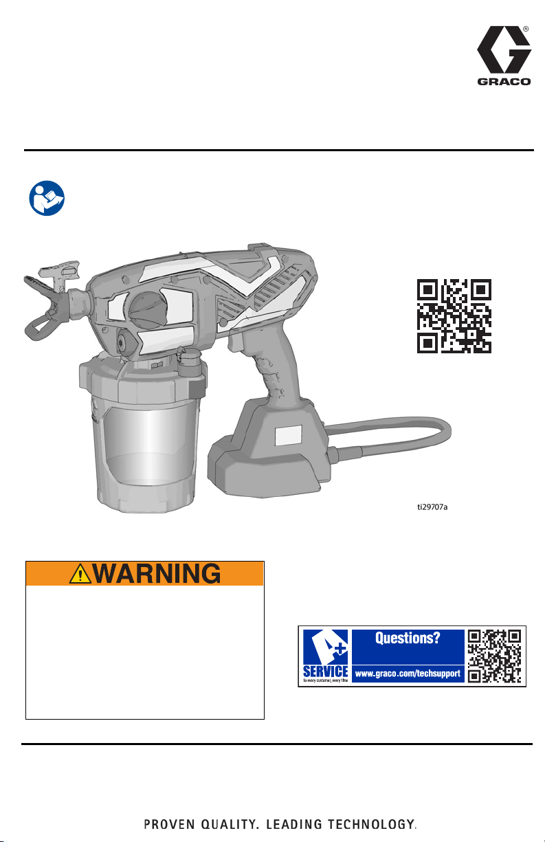
Operation, Parts
Corded Airless
HandHeld Sprayers
Important Safety Instructions
Read all warnings and instructions in this manual and on the unit. Be familiar with the
controls and the proper usage of the equipment. Save these instructions.
3A4433D
EN
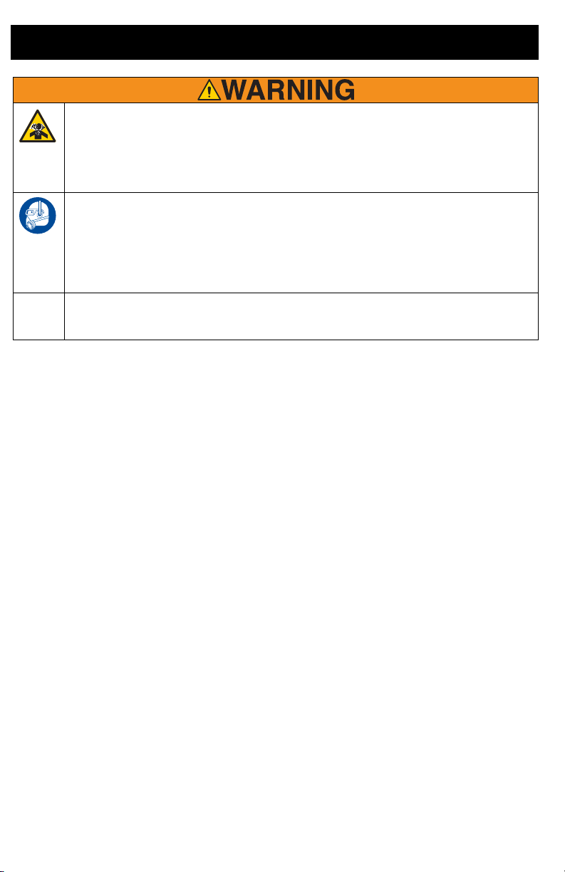
FIRE AND EXPLOSION HAZARD
Use only non-flammable or water-based
materials, or non-flammable paint thinners. Do
not use materials having flash points below
100°F (38°C). This includes, but is not limited to,
acetone, xylene, toluene, and naphtha. For
more information about your material, request
Safety Data Sheet (SDS) from the supplier.
Use oil-based materials outdoors or in a
well-ventilated indoor area with a flow of fresh air.
For portable spray applications of water-based and oil-based
non-flammable architectural paints and coatings only.
Not approved for use in explosive atmospheres or hazardous locations.
Page 2

Contents
Contents
Models – Corded Airless HandHelds . . . . . . . . . . . . . . . . . . . . . . . . . . . . . . . 3
Important User Information . . . . . . . . . . . . . . . . . . . . . . . . . . . . . . . . . . . . . . . 4
Warnings . . . . . . . . . . . . . . . . . . . . . . . . . . . . . . . . . . . . . . . . . . . . . . . . . . . . . . 5
Know Your Sprayer . . . . . . . . . . . . . . . . . . . . . . . . . . . . . . . . . . . . . . . . . . . . . . 9
Start Up . . . . . . . . . . . . . . . . . . . . . . . . . . . . . . . . . . . . . . . . . . . . . . . . . . . . . . 10
Pressure Relief Procedure . . . . . . . . . . . . . . . . . . . . . . . . . . . . . . . . . . . . . 10
Starting a New Job . . . . . . . . . . . . . . . . . . . . . . . . . . . . . . . . . . . . . . . . . . . 10
Refilling FlexLiner . . . . . . . . . . . . . . . . . . . . . . . . . . . . . . . . . . . . . . . . . . . . 13
How to Spray . . . . . . . . . . . . . . . . . . . . . . . . . . . . . . . . . . . . . . . . . . . . . . . . . . 14
Speed Control . . . . . . . . . . . . . . . . . . . . . . . . . . . . . . . . . . . . . . . . . . . . . . . 14
Tip and Pressure Selection . . . . . . . . . . . . . . . . . . . . . . . . . . . . . . . . . . . . . 14
Spray Techniques . . . . . . . . . . . . . . . . . . . . . . . . . . . . . . . . . . . . . . . . . . . . 14
Triggering Sprayer . . . . . . . . . . . . . . . . . . . . . . . . . . . . . . . . . . . . . . . . . . . 15
Aiming Sprayer . . . . . . . . . . . . . . . . . . . . . . . . . . . . . . . . . . . . . . . . . . . . . . 15
Spray Pattern Quality . . . . . . . . . . . . . . . . . . . . . . . . . . . . . . . . . . . . . . . . . 16
Clear Tip Clog . . . . . . . . . . . . . . . . . . . . . . . . . . . . . . . . . . . . . . . . . . . . . . . 16
Cleanup . . . . . . . . . . . . . . . . . . . . . . . . . . . . . . . . . . . . . . . . . . . . . . . . . . . . . . 18
Cleaning Sprayer . . . . . . . . . . . . . . . . . . . . . . . . . . . . . . . . . . . . . . . . . . . . 18
Cleaning VacuValve . . . . . . . . . . . . . . . . . . . . . . . . . . . . . . . . . . . . . . . . . . 21
Storage . . . . . . . . . . . . . . . . . . . . . . . . . . . . . . . . . . . . . . . . . . . . . . . . . . . . . . . 22
Common Procedures . . . . . . . . . . . . . . . . . . . . . . . . . . . . . . . . . . . . . . . . . . . 23
Spray Tip Installation . . . . . . . . . . . . . . . . . . . . . . . . . . . . . . . . . . . . . . . . . 23
Flush a New Sprayer . . . . . . . . . . . . . . . . . . . . . . . . . . . . . . . . . . . . . . . . . 23
Reference . . . . . . . . . . . . . . . . . . . . . . . . . . . . . . . . . . . . . . . . . . . . . . . . . . . . . 26
Spray Tip Selection . . . . . . . . . . . . . . . . . . . . . . . . . . . . . . . . . . . . . . . . . . . 26
Cleaning Fluid Compatibility . . . . . . . . . . . . . . . . . . . . . . . . . . . . . . . . . . . . 27
Static Grounding Instructions (Oil-Based materials) . . . . . . . . . . . . . . . . . . 27
Maintenance . . . . . . . . . . . . . . . . . . . . . . . . . . . . . . . . . . . . . . . . . . . . . . . . . . 28
Cleaning Outlet Valves . . . . . . . . . . . . . . . . . . . . . . . . . . . . . . . . . . . . . . . . 28
Replacement Parts . . . . . . . . . . . . . . . . . . . . . . . . . . . . . . . . . . . . . . . . . . . . . 30
Parts List . . . . . . . . . . . . . . . . . . . . . . . . . . . . . . . . . . . . . . . . . . . . . . . . . . . 31
Troubleshooting . . . . . . . . . . . . . . . . . . . . . . . . . . . . . . . . . . . . . . . . . . . . . . . 32
Technical Specifications . . . . . . . . . . . . . . . . . . . . . . . . . . . . . . . . . . . . . . . . 37
Graco Limited Warranty . . . . . . . . . . . . . . . . . . . . . . . . . . . . . . . . . . . . . . . . . 39
Certified to CAN/CSA C22.2 No. 68
2 3A4433D
110474
Conforms to UL 1450
Page 3

Models – Corded Airless HandHelds
Models – Corded Airless HandHelds
Model Sprayer Name Voltage Tip Family Tip Size
17M359 Ultra 120V FFLPxxx
0.008 – 0.016 in. (0.20 – 0.41 mm)17N162 Ultimate 120V FFLPxxx
17N163 TC Pro 120V TCPxxx
Operating pressure range: 500-2000 psi (35 – 138 bar, 3.5 MPa – 14 MPa)
3A4433D 3
Page 4

Important User Information
Important User Information
Thank You for Your Purchase!
Before using your sprayer read this Owners Manual for complete instructions on proper use and
safety warnings.
Congratulations! You have purchased a high-quality paint sprayer made by Graco Inc. This
sprayer is designed to provide superior spray performance with water-based and oil-based
(mineral spirit-type) architectural paints and coatings. This user information is intended to help
you understand the types of materials that can be used with your sprayer.
Please read the information on the material container label to determine if it can be used with
your sprayer. Ask for a Safety Data Sheet (SDS) from your supplier. The container label and
SDS will explain the contents of the material and the specific precautions related to it.
Paints, coatings and clean-up materials generally fit
into one of the following 3 basic categories:
WATER-BASED: The container label should indicate that the material can be
cleaned up with soap and water. Your sprayer is compatible with this type of
material. Your sprayer is NOT compatible with harsh cleaners such as chlorine
bleach.
OIL-BASED: The container label should indicate that the material is
COMBUSTIBILE and can be cleaned up with mineral spirits or non-flammable paint
thinner. The SDS must indicate that the flash point of the material is above 100°F
(38°C). Your sprayer is compatible with this type of material. Use oil-based material
outdoors or in a well-ventilated indoor area with a flow of fresh air. See the safety
warnings in this manual.
FLAMMABLE: This type of material contains flammable solvents such as xylene,
toluene, naphtha, MEK, lacquer thinner, acetone, denatured alcohol, and
turpentine. The container label should indicate that this material is
FLAMMABLE. This type of material is NOT compatible with your sprayer
and CANNOT be used.
4 3A4433D
Page 5
Warnings
ti3509b
Conductor Size Length
AWG (American Wire Gauge) Metric Maximum
18
1.0 mm
2
50 ft. (15 m)
16
1.5 mm
2
100 ft. (30 m)
14
2.5 mm
2
200 ft. (61 m)
Warnings
The following warnings are for the setup, use, maintenance, and repair of this equipment. The
exclamation point symbol alerts you to a general warning and the hazard symbols refer to
procedure-specific risks. When these symbols appear in the body of this manual or on warning labels,
refer back to these Warnings. Product-specific hazard symbols and warnings not covered in this
section may appear throughout the body of this manual where applicable.
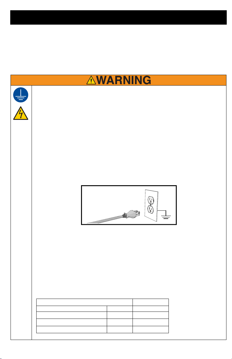
GROUNDING
This product must be grounded. In the event of an electrical short circuit, grounding reduces
the risk of electric shock by providing an escape wire for the electric current. This product is
equipped with a cord having a grounding wire with an appropriate grounding plug. The plug
must be plugged into an outlet that is properly installed and grounded in accordance with all
local codes and ordinances.
• Improper installation of the grounding plug is able to result in a risk of electric shock.
• When repair or replacement of the cord or plug is required, do not connect the grounding
wire to either flat blade terminal.
• The wire with insulation having an outer surface that is green with or without yellow stripes
is the grounding wire.
• Check with a qualified electrician or serviceman when the grounding instructions are not
completely understood, or when in doubt as to whether the product is properly grounded.
• Do not modify the plug provided; if it does not fit the outlet, have the proper outlet installed
by a qualified electrician.
• This product is for use on a nominal 120V circuit and has a grounding plug similar to the
plug illustrated below.
• Only connect the product to an outlet having the same configuration as the plug.
• Do not use an adapter with this product.
Extension Cords:
•
Use only a 3-wire extension cord that has a grounding plug and a grounding receptacle that
accepts the plug on the product.
• An undersized cord results in a drop in line voltage and loss of power and
overheating.When in doubt use the next heavier gauge. The smaller the gauge number the
heavier the cord.
• When using the sprayer outdoors, use an extension cord suitable for outdoor use.
•
Make sure your extension cord is not damaged. When using an extension cord, be sure to
use a cord heavy enough to carry the current that your sprayer draws. See chart for
appropriate sizes and lengths:
3A4433D 5
Page 6
Warnings
FIRE AND EXPLOSION HAZARD
Flammable fumes, such as solvent and paint fumes, in work area can ignite or explode. To help
prevent fire and explosion:
• Sprayer generates sparks. Do not spray or flush with flammable liquids.
• Do not spray or clean with materials having a flash point lower than 100° F (38° C).
• Use only non-flammable or water-based materials, or non-flammable paint thinners.
• Keep spray area well-ventilated. Keep a good supply of fresh air moving through the area.
• When spraying oil-based material, use outdoors or in a well-ventilated indoor area with a
flow of fresh air.
• Do not spray combustible materials near an open flame or sources of ignition such as
cigarettes, motors, and electrical equipment.
• Paint or solvent flowing through the equipment is able to result in static electricity. Static
electricity creates a risk of fire or explosion in the presence of paint or solvent fumes.
• Keep sprayer at least 10 in. (25 cm) away from objects while spraying or flushing.
• Verify all containers and collection systems are grounded to prevent static discharge.
• Connect to a grounded outlet and use grounded extension cords. Do not use a 3 to 2
adapter.
• Do not use paints or solvents containing halogenated hydrocarbons.
• Do not smoke in the spray area.
• Do not operate light switches, engines, or similar spark producing products in the spray
area.
• Keep area clean and free of paint or solvent containers, rags, and other flammable
materials.
• Know the contents of the paints and solvents being sprayed. Read all Safety Data Sheets
(SDS) and container labels provided with the paints and solvents. Follow the paint and
solvents manufacturer’s safety instructions.
• Fire extinguisher equipment shall be present and working.
ELECTRIC SHOCK HAZARD
This equipment must be grounded. Improper grounding, setup, or usage of the system can
cause electric shock.
• Turn off and disconnect power cord before servicing equipment.
• Connect only to grounded electrical outlets.
• Use only 3-wire extension cords.
• Ensure ground prongs are intact on power and extension cords.
• Do not expose to rain. Store indoors.
6 3A4433D
Page 7
Warnings
SKIN INJECTION HAZARD
High-pressure spray is able to inject toxins into the body and cause serious bodily injury. In the
event that injection occurs, get immediate surgical treatment.
• Do not aim the sprayer at, or spray any person or animal.
• Keep hands and other body parts away from the discharge. For example, do not try to stop
leaks with any part of the body.
• Disconnect power when not spraying.
• Always use the spray tip guard. Do not spray without spray tip guard in place. Use only
Graco spray tips.
• Use caution when cleaning and changing spray tips. In the case where the spray tip clogs
while spraying, follow the Pressure Relief Procedure, page 10 for relieving the pressure
before removing the spray tip to clean.
• Do not leave the unit energized or under pressure while unattended. Unplug the sprayer
and follow the Pressure Relief Procedure, page 10 when the equipment is unattended
or not in use and before servicing, cleaning, or removing parts.
• Check parts for signs of damage. Replace any damaged parts.
• This system is capable of producing 2000 psi (138 bar, 14 MPa). Use replacement parts
or accessories that are rated a minimum of 2000 psi (
• Do not carry the unit with a finger on the trigger.
• Verify that all connections are secure before operating the unit.
• Know how to stop the unit and bleed pressure quickly. Be thoroughly familiar with the
controls.
EQUIPMENT MISUSE HAZARD
Misuse can cause death or serious injury.
• Always wear appropriate gloves, eye protection, and a respirator or mask when painting.
• Do not operate or spray near children. Keep children away from equipment at all times.
• Do not overreach or stand on an unstable support. Keep effective footing and balance at
all times.
• Stay alert and watch what you are doing.
• Do not operate the unit when fatigued or under the influence of drugs or alcohol.
• Do not alter or modify equipment. Alterations or modifications may void agency approvals
and create safety hazards.
• Use only in dry locations. Do not expose to water or rain.
• Use in well-lit areas.
•
Make sure all equipment is rated and approved for the environment in which you are using it.
PRESSURIZED ALUMINUM PARTS HAZARD
Use of fluids that are incompatible with aluminum in pressurized equipment can cause serious
chemical reaction and equipment rupture. Failure to follow this warning can result in death,
serious injury, or property damage.
• Do not use 1,1,1-trichloroethane, methylene chloride, other halogenated hydrocarbon
solvents or fluids containing such solvents.
• Do not use chlorine bleach.
• Many other fluids may contain chemicals that can react with aluminum. Contact your
material supplier for compatibility.
138 bar, 14 MPa).
3A4433D 7
Page 8
Warnings
TOXIC FLUID OR FUMES HAZARD
Toxic fluids or fumes can cause serious injury or death if splashed in the eyes or on skin,
inhaled, or swallowed.
• Read Safety Data Sheets (SDSs) to know the specific hazards of the fluids you are using.
• Store hazardous fluid in approved containers, and dispose of it according to applicable
guidelines.
PERSONAL PROTECTIVE EQUIPMENT
Wear appropriate protective equipment when in the work area to help prevent serious injury,
including eye injury, hearing loss, inhalation of toxic fumes, and burns. This protective
equipment includes but is not limited to:
• Protective eye-wear, and hearing protection.
• Respirators, protective clothing, and gloves as recommended by the fluid and solvent
manufacturer.
CALIFORNIA PROPOSITION 65
This product contains a chemical known to the State of California to cause cancer, birth defects
or other reproductive harm. Wash hands after handling.
8 3A4433D
Page 9
Know Your Sprayer
A
SPRAY PRIME
D
E
L
GM K
T
T
F
B
C
ti29712a
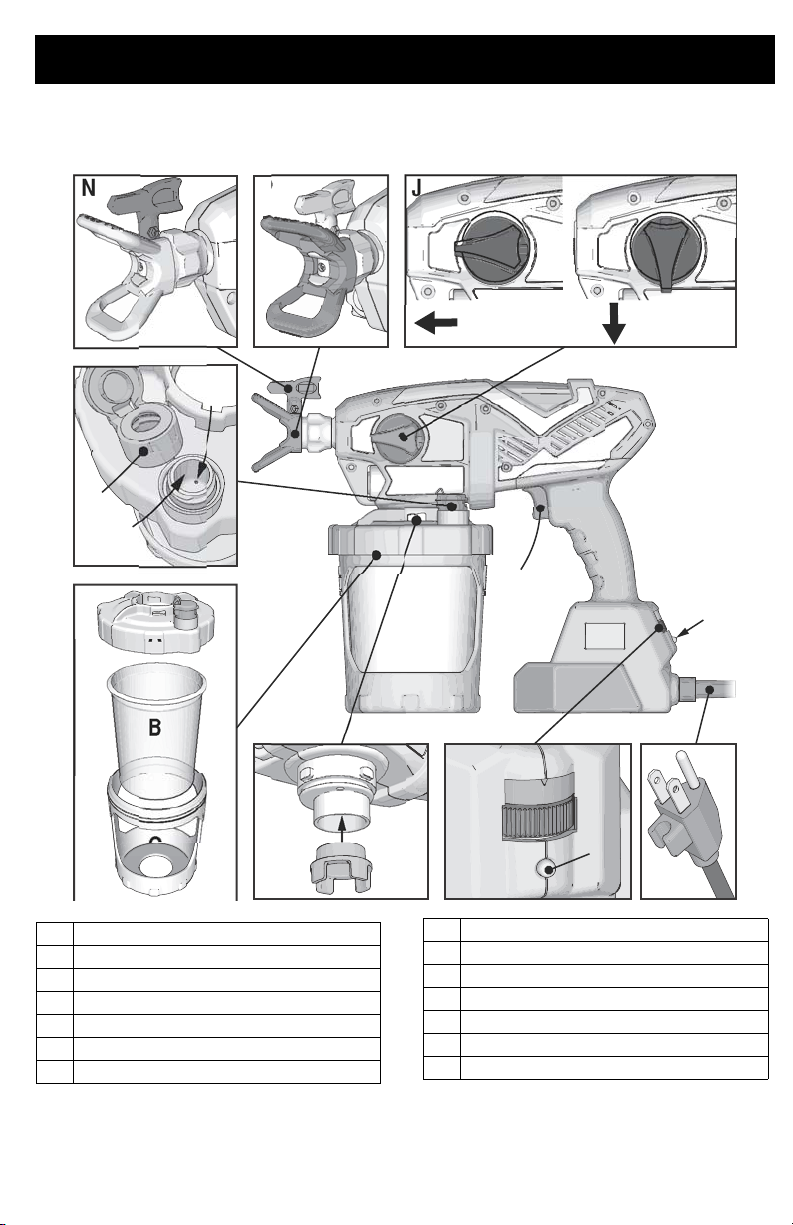
Know Your Sprayer
N
PJ
A Cup Cover
B FlexLiner
C Cup Support
D VacuValve Cap
E VacuValve Air Hole
F VacuValve Reservoir
G Pump Filter
3A4433D 9
J Prime Pump/Spray Knob
KPower Cord
L Sprayer Trigger
M Speed Control, ProControl II
N Spray Tip. Reverse-A-Clean (RAC)
P Spray Tip Guard
T
Diagnostic Light
Page 10
Start Up
ti26894a
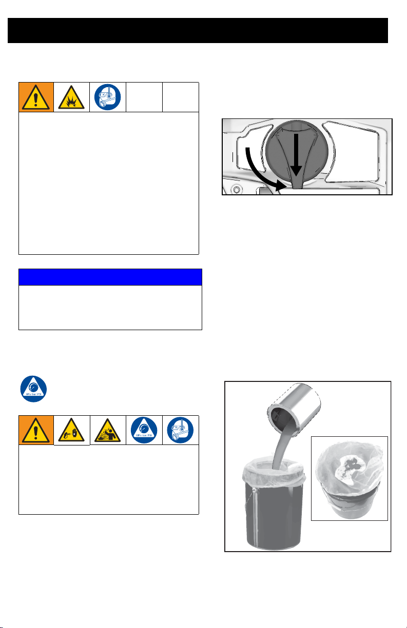
Start Up
Use only oil-based (non-flammable) or
water-based materials, or non-flammable
paint thinners. Do not use materials having
flash points below 100°F (38°C).
Do not use materials which state
“FLAMMABLE” on the packaging. For
more information about your material,
request SDS from distributor or retailer.
When spraying oil-based material, use
outdoors or in a well-ventilated indoor area
with a flow of fresh air.
Keep spray area well-ventilated. Keep a
good supply of fresh air moving through the
area.
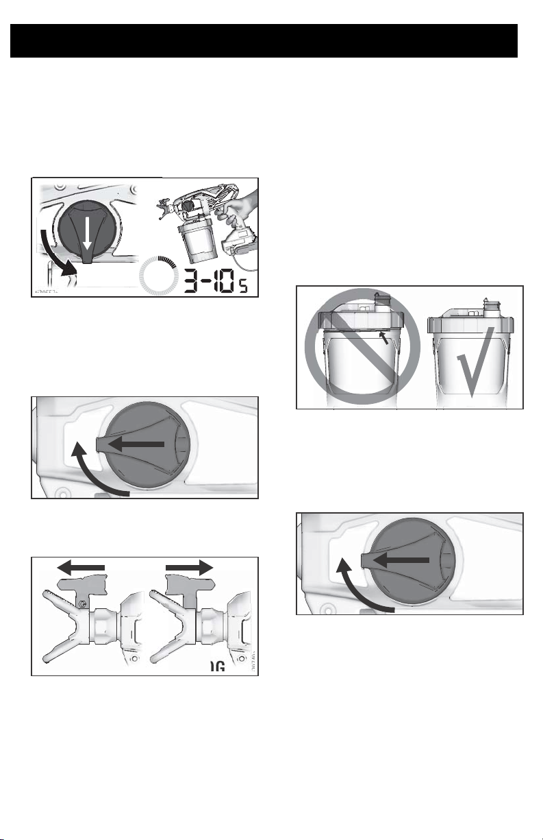
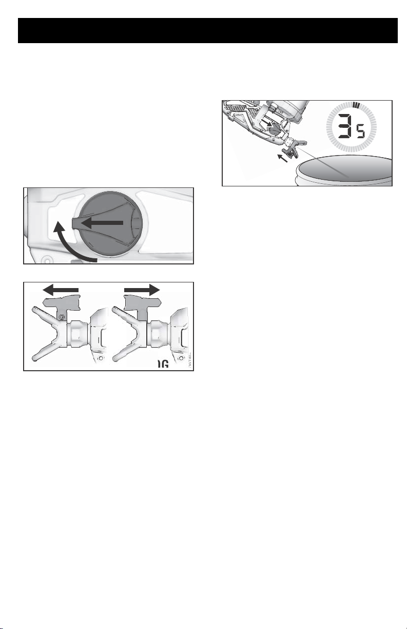
2. Turn Prime Pump/Spray Knob down to
PRIME PUMP position to relieve
pressure.
ti29755a
Starting a New Job
If you are using the sprayer for the very first
time, see Flush a New Sprayer, page 23.
NOTICE
Your sprayer is
cleaners such as chlorine bleach. Using
these cleaners will cause damage to the
sprayer.
NOT
compatible with harsh
Pressure Relief Procedure
Follow the Pressure Relief
Procedure whenever you see this
symbol.
This sprayer builds up an internal pressure
of 2000 psi (14 MPa, 138 bar) during use.
Follow this Pressure Relief Procedure
whenever you stop spraying and before
cleaning, checking, servicing, or
transporting equipment to prevent serious
injury.
1. Disconnect power (unplug power cord).
Strain the Paint
Previously opened paint may contain dried
paint or other debris. To avoid priming
problems and tip clogs it is advisable to strain
the paint before using. Paint strainers are
available where paint is sold. Stretch a paint
strainer over a clean pail and pour the paint
through the strainer to capture any dried paint
and debris before spraying.
10 3A4433D
Page 11
Start Up
ti23361a
ti29719a
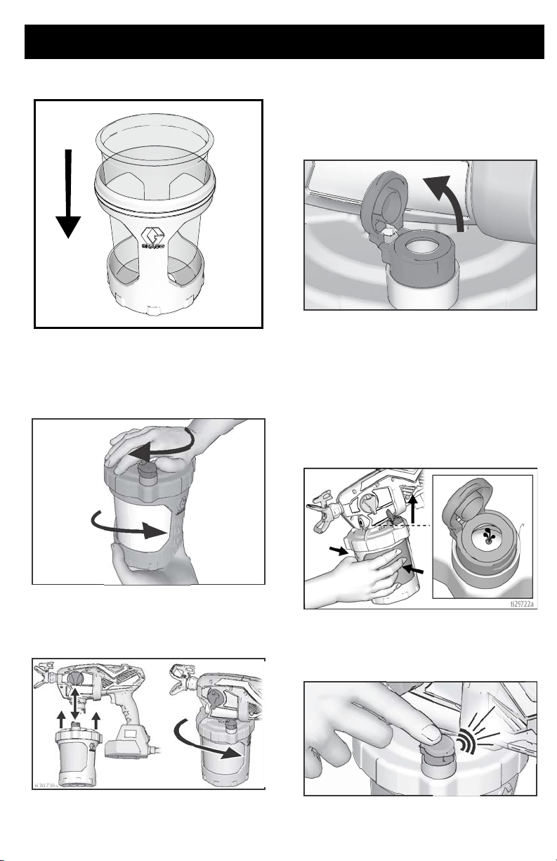
1. Install FlexLiner in the cup support.
2. Fill FlexLiner with material. Securely
tighten cup cover onto cup support.
proper sprayer operation lid must seal
tightly with the cup.
For
4. The VacuValve is an important part of
your new sprayer. It is used to evacuate
the air out of the FlexLiner. Your sprayer
will not spray if there is air in the
FlexLiner.
ti29721a
5. Open VacuValve cap.
Tilt the sprayer so
the VacuValve is the highest point,
causing any air in the FlexLiner to rise to
the VacuValve. Gently squeeze the
FlexLiner to evacuate all air through the
VacuValve air hole. Once you see
material enter the VacuValve reservoir,
all air should be evacuated from the
FlexLiner.
3. Align VacuValve on cup cover with
Prime Pump/Spray knob. Push cup
assembly onto sprayer and twist to lock.
6. Stop squeezing the FlexLiner and snap
the VacuValve cap closed. You will hear
the cap click when it is closed properly.
ti29720a
ti29723a
3A4433D 11
Page 12
Start Up
ti29739a
ti29741a
ti29739a
7. Plug sprayer into power source.
8. Turn Prime Pump/Spray knob down to
Prime Pump position. Turn spray tip to
UNCLOG position. To fill sprayer with
fluid, point sprayer into a waste area and
hold the trigger in for
ti30557a
9. Air from pump may have entered the
FlexLiner during priming. Repeat Steps
4 – 6 to ensure all air is evacuated.
10. Turn Prime Pump/Spray knob forward to
spray position.
3 – 10 seconds.
If sprayer does not spray, try one of
the steps below:
•
Make certain there is only one FlexLiner
in cup support. It is possible for two liners
to nest tightly together and appear as
only one.
• Make certain the cup cover is properly
threaded to the cup support. If threads
are visible below the cup cover when
tight, then the cover is cross-threaded.
Fully remove the cup cover and reinstall
to the cup support so no threads are
visible when tight.
• Repeat steps 2 – 6 on pages 11 – 11 to
ensure all the air is evacuated from the
FlexLiner.
• Make certain the Prime Pump/Spray
knob is in the Spray position.
11. Make certain spray tip is in the spray
position.
•
If sprayer still does not spray, see
Sprayer Diagnostics
SPRAY UNCLOG
12. You are now ready to spray.
NOTE: For best results; to evacuate all
material from the FlexLiner when the material
is nearly gone, gently squeeze the bottom of
the FlexLiner to push the last of the material
up to the cup lid.
12 3A4433D
ti29740a
material sprays while upside down there
is air in the cup. Repeat steps above.
•
Replace VacuValve cap. Two new
VacuValve caps came with your sprayer.
, page 32. If
Page 13

Refilling FlexLiner
If sprayer runs out of paint simply separate
the cup support from the cup cover/sprayer
and refill the FlexLiner.
1. Unplug sprayer from power source and
open the VacuValve to allow air into the
FlexLiner.
2. Separate the cup support from the
cover/sprayer.
down on a flat surface. This will keep the
wet paint in the cup cover.
Set the sprayer upside
cup
Start Up
ti29742a
3. Follow steps 2 – 12 in Starting a New
Job, page 10.
3A4433D 13
Page 14

How to Spray
How to Spray
Speed Control
Take a few moments prior to spraying and
review these simple tips to ensure your
spraying project is a success.
NOTE: For proper sprayer operation use only
a tip from the same tip family that came with
your sprayer.
Sprayer Name Tip Family Tip Part No.
Ultra FFLP FFLPxxx
Ultimate FFLP FFLPxxx
TC Pro TCP TCPxxx
Tip and Pressure Selection
See table for recommended spray pressure for your material. Refer to paint (material) can for
manufacturer’s recommendations.
Interior
Stains/
Interior &
Exterior
Clears
Speed Control 1 – 5 6 – 10 6 – 10 6 – 10 6 – 10 6 – 10
Tip hole Size
0.008 in. (0.20 mm)
0.010 in. (0.25 mm)
0.012 in. (0.30 mm)
0.014 in. (0.36 mm)
0.016 in. (0.41 mm)
Exterior
Solid Stains Primers Enamels
The speed control allows for infinite pressure
adjustment. To reduce overspray, always
start at lowest speed setting and increase
speed to the minimum setting that results in
an acceptable spray pattern.
Coatings
Interior
Latex
Paints
Exterior
Latex
Paints
ti29773a
Spray Techniques
Use a piece of scrap cardboard to practice
these basic spraying techniques before you
begin spraying the surface.
• Hold sprayer 12 in. (30 cm) from surface
and aim straight at surface. Tilting the
sprayer to direct the spray angle causes
an uneven finish.
14 3A4433D
• Flex wrist to keep sprayer pointed
straight. Fanning sprayer to direct spray
at angle causes uneven finish.
NOTE: How fast you move the sprayer will
affect spray application. If material is uneven,
you are moving too fast. If material drips, you
are moving too slow. See Troubleshooting,
page 32.
Page 15

How to Spray
ti29743a
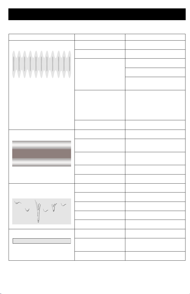
EVEN
FINISH
12 in.
UNEVEN
FINISH
THICK
THIN
(30 cm)
ti29744a
EVEN FINISH
THICK THINTHIN
ti29745a
Triggering Sprayer
Pull trigger after starting stroke. Release
trigger before end of stroke. Sprayer must be
moving when trigger is pulled and released.
ti30015a
Aiming Sprayer
Aim sprayer at bottom edge of previous
stroke, overlapping each stroke by half.
Rotating the spray tip guard changes the
3A4433D 15
pattern to either the vertical or horizontal
orientations.
Page 16

How to Spray
ti29746a
GOOD PATTERN
BAD PATTERN
TAILS
TAILS
When spraying vertical corners turn spray tip
guard to the horizontal orientation and move
sprayer up and down.
Spray Pattern Quality
A good spray pattern is evenly distributed as
it hits the surface.
• Spray should be atomized (evenly
distributed, no gaps at edges).
Clear Tip Clog
In the event that particles or debris clog the
spray tip, this sprayer is designed with a
reversible spray tip that quickly and easily
clears the particles without disassembling the
sprayer. See for Strain the Paint, page 10 for
additional information.
1. To unclog spray tip, turn Prime
Pump/Spray knob down to Prime Pump
position.
ti29755a
2. Reverse spray tip to UNCLOG position.
SPRAY UNCLOG
ti29754a
If tails persist when spraying at the highest
spray pressure:
• Spray tip may be worn. See Tip and
Pressure Selection, page 14.
• A smaller spray tip may be needed.
• Material may need to be thinned. Follow
manufacturers recommendations.
16 3A4433D
3. Set speed control to 10.
ti29773a
ti29740a
Page 17

How to Spray
4. Aim sprayer at waste area, turn Prime
Pump/Spray knob forward to spray
position. Pull trigger to clear clog.
ti29774a
5.
Turn Prime Pump/Spray knob down to
Prime position.
SPRAY position. Turn Prime
Pump/Spray knob forward to SPRAY
position, and resume spraying.
6. If spray tip is still clogged, you may have
to repeat steps 1
spray tip assembly. See Spray Tip
Installation, page 23.
Rotate spray tip back to
– 5, or replace with new
3A4433D 17
Page 18
Cleanup
ti29756a
Cleanup
Use only oil-based (non-flammable) or
water-based materials, or non-flammable
paint thinners. Do not use materials having
flash points below 100°F (38°C).
Do not use materials which state
“FLAMMABLE” on the packaging. For
more information about your material,
request SDS from distributor or retailer.
Clean in a well-ventilated area. Keep a
good supply of fresh air moving through the
area.
To avoid serious injury or damage to
equipment, do not expose the sprayer
electronics to cleaning fluids. Keep sprayer
at least 10 in. (25 cm) above the rim of the
container when cleaning.
Cleaning Sprayer
Cleaning your sprayer properly and after
every spray job is of the utmost importance!
Proper care and maintenance will make your
paint sprayer last and work for you trouble
free.
See
Cleaning Fluid Compatibility,
and
page 27
(Oil-Based materials), page 27
information when using oil-based materials.
1. Turn Prime Pump/Spray knob to Prime
Pump to relieve pressure.
2. Open the VacuValve to allow air into the
FlexLiner.
3. Separate the cup support with FlexLiner
from the cup cover/sprayer.
18 3A4433D
Static Grounding Instructions
for additional
4. Set the sprayer upside down on a flat
surface. This will keep the wet paint in
the cup cover. Return excess material to
original container. Hold the FlexLiner in
place when pouring.
ti29759a
Page 19
5. You can either dispose of the used
ti29756b
ti29767a
FlexLiner and install a new FlexLiner or
clean a used FlexLiner.
6. To clean the sprayer, fill FlexLiner
approximately half-full with appropriate
cleaning fluid (warm water or mineral
spirits).
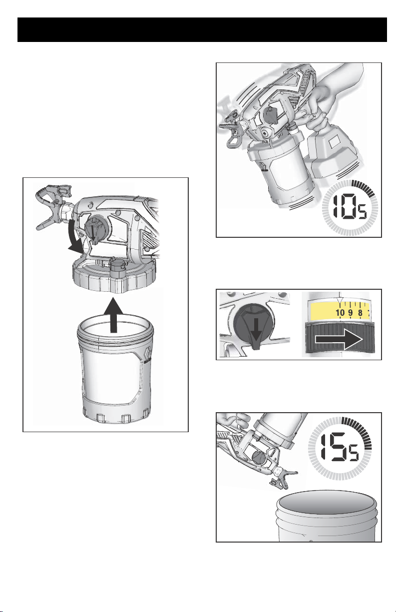
7. Securely tighten cup support with
FlexLiner to cup cover/sprayer and close
VacuValve.
Cleanup
ti29760b
9. Make certain the Prime Pump/Spray
knob is in the Prime Pump position
(pointed down). Set speed control to 10.
10. Turn the sprayer upside down and point
the sprayer into a waste pail. Pull the
trigger for 15 seconds.
8. To clean the cup cover and pump filter
and shake the entire sprayer for ten
seconds.
3A4433D 19
ti29766a
Page 20
Cleanup
ti30231a
11. Turn Prime Pump/Spray knob forward to
SPRAY position.
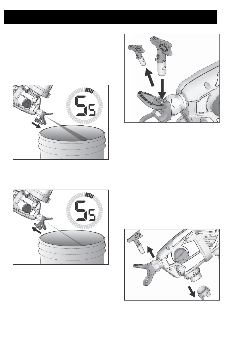
12. While holding the sprayer upside down
point the sprayer into a waste pail.
a. With the spray tip in the SPRAY
position, pull the trigger for five
seconds. Release the trigger.
b. Reverse the spray tip to UNCLOG
position, pull the trigger for five
seconds. Release the trigger.
ti29768a
14. Remove cup assembly and discard used
fluid. Dispose of used cleaning fluid
properly.
15. Replace cleaning fluid and repeat steps
6 – 14 until spray output is clean.
IMPORTANT! For best results, do not spray
more than one cup of water through the tip
while cleaning. If more flushing is needed,
remove the tip from the sprayer to avoid
excessive wear.
16. Remove spray tip, spray tip guard, and
pump filter. Clean with appropriate
cleaning fluid (water or mineral spirits). A
soft brush can be used to loosen and
remove dried material if needed.
ti30232a
13. If second spray tip was used, remove
cleaned spray tip from spray tip guard
and install second spray tip. See
Tip Installation
, page 23. Repeat steps
11 and 12 to clean second spray tip.
Spray
ti29769a
20 3A4433D
Page 21
Cleanup
ti23372a
ti23406a
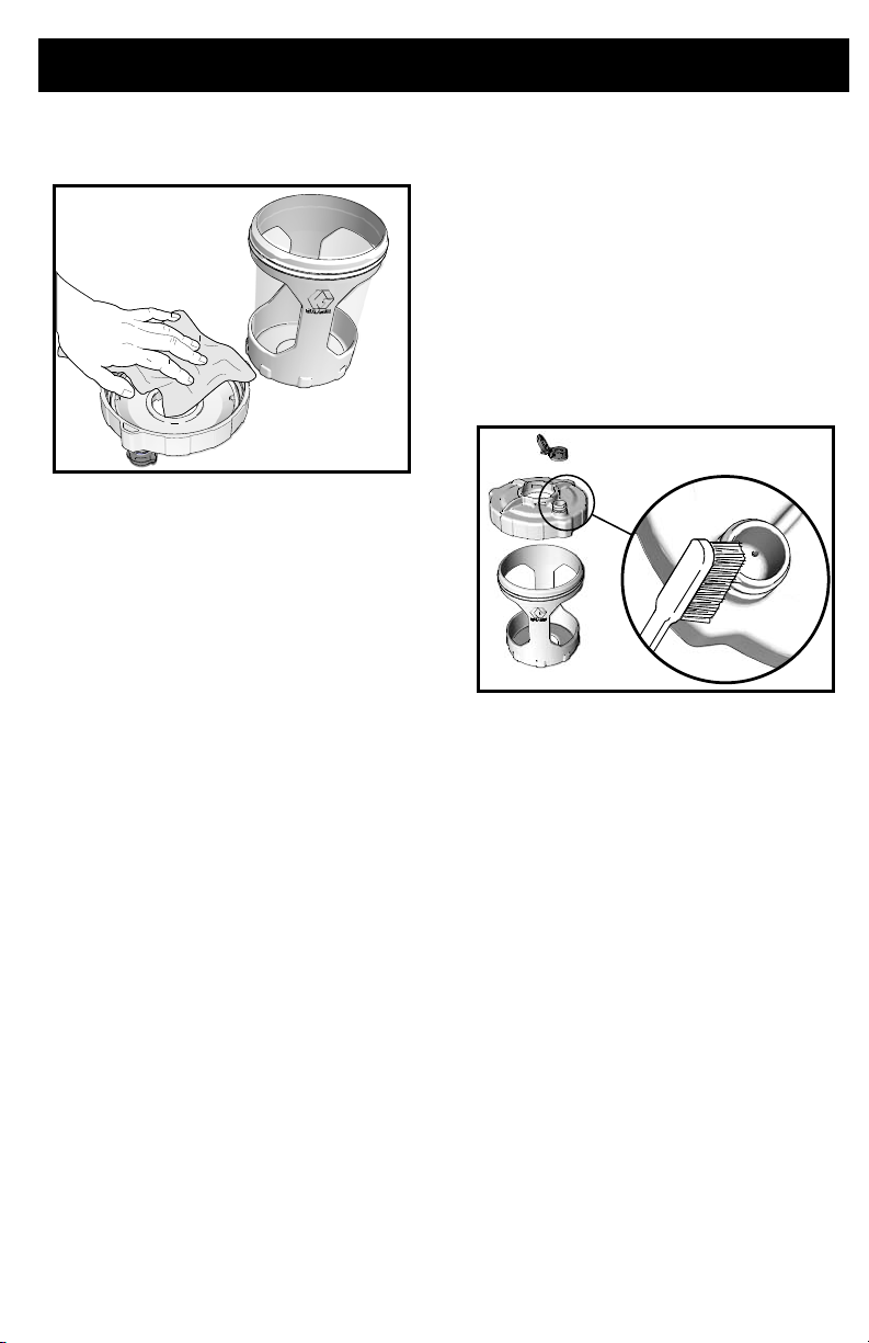
17. Use a soft cloth to clean the cup support
and cup cover.
Cleaning VacuValve
The VacuValve is an important part of your
sprayer and it should be cleaned after every
use.
1. Remove VacuValve cap from cup cover
and clean it.
2. Clean VacuValve reservoir in lid.
3. Clean VacuValve air hole. If VacuValve
air hole becomes clogged, use a paper
clip to clean the hole.
3A4433D 21
Page 22
Storage
ti29770a
ti29771a
Storage
With proper storage, the sprayer will be ready
to use the next time it is needed.
NOTICE
Failure to store sprayer with Pump Armor
can result in operational problems the next
time you spray. Always circulate Pump
Armor through the sprayer after cleaning.
Water or solvents other than mineral
spirits left in the sprayer will corrode
and damage the pump.
Pump Armor fluid protects the sprayer while
in storage. It helps protect sprayer against
freezing and corrosion when not in use.
1. Clean the sprayer and cup assembly.
See Cleanup, page 18.
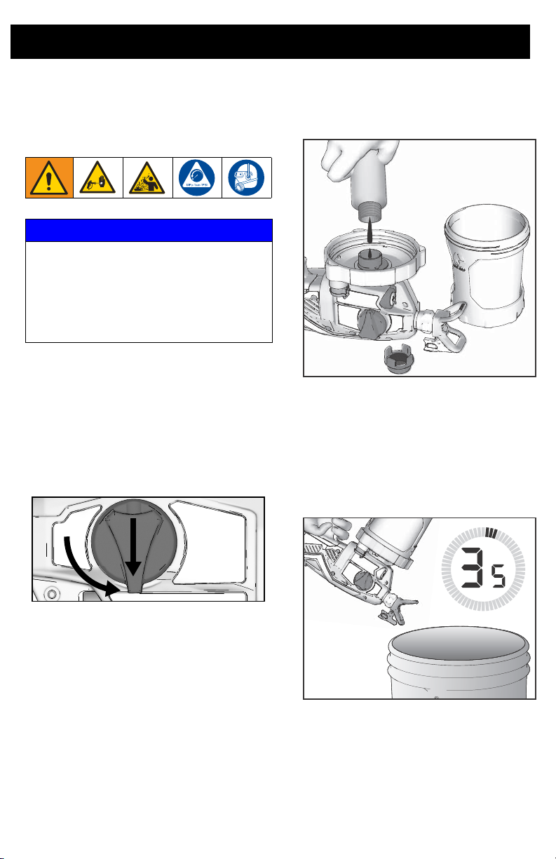
2. Turn Prime Pump/Spray knob down to
the Prime Pump position. Make certain
that VacuValve cap is closed.
5. With the sprayer upside-down pour
approximately 2 oz. (60 ml) PUMP
ARMOR into pump opening.
6. Install a clean pump filter into pump
opening.
7. With sprayer upside-down attach cup
support with FlexLiner to sprayer.
8. Holding sprayer upside-down over a
waste container, pull sprayer trigger for
three seconds.
ti29755a
3. Separate the cup support with FlexLiner
from the cup cover/sprayer. Set the
sprayer upside down on a flat surface.
4. Remove pump filter from pump opening.
Turn Prime Pump/Spray knob forward to
9.
spray position. Remove cup assembly
and pour any remaining Pump Armour
back into Pump Armor bottle. Replace
child-resistant cap and tighten securely
for storage.
10. Store sprayer indoors in a cool, dry place.
Store in an
22 3A4433D
upright position only
.
Page 23
Common Procedures
ti24653a
C
B
A
ti24664a
ti29775a
Common Procedures
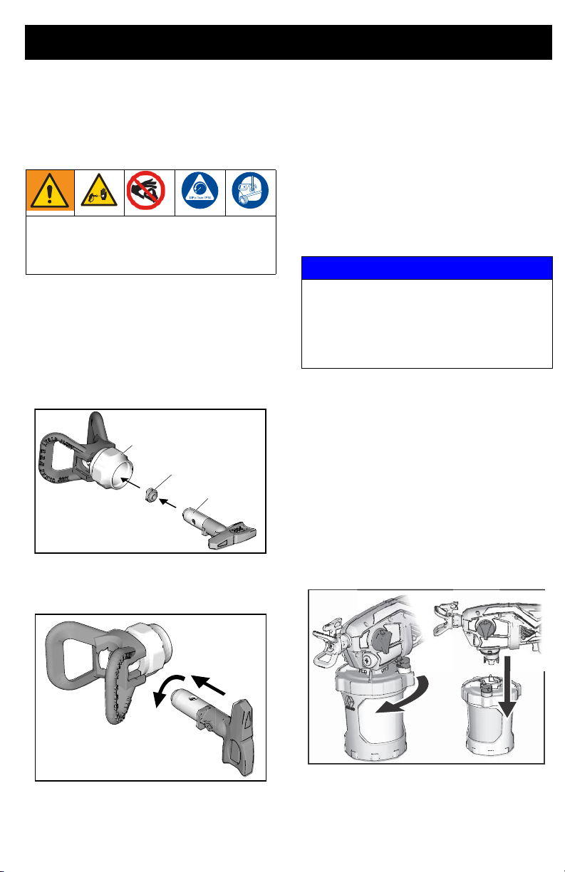
Spray Tip Installation
To avoid serious injury from skin injection
do not put your hand in front of the spray tip
when installing or removing the spray tip
and tip guard.
To prevent spray tip leaks make certain spray
tip and tip guard are installed properly.
1. Perform Pressure Relief Procedure,
page 10.
2.
Use spray tip (A) to insert seal (B)
into tip guard (C).
3. Insert Spray Tip. Spray tip must be
pushed all the way into the tip guard.
4. Screw spray tip and tip guard assembly
onto the gun and hand tighten.
• Spray tips wear with use and abrasive
paint and need periodic replacement.
• If the spray pattern is poor, you may have
a worn spray tip. Replace spray tip. See
Spray Pattern Diagnostics, page 35.
NOTICE
Spray tips must be cleaned or stored in
appropriate cleaning fluid (water or mineral
spirits) immediately after use to ensure
material is not allowed to dry in spray tip.
Failure to do so will result in damage to the
spray tip. See Cleanup, page 18.
Flush a New Sprayer
This sprayer arrives from the factory with a
small amount of test material in the system.
is important that you flush this material
from the sprayer before using it for the first
time.
See
Cleaning Fluid Compatibility
page 27 and
(Oil-Based materials)
information when using oil-based materials.
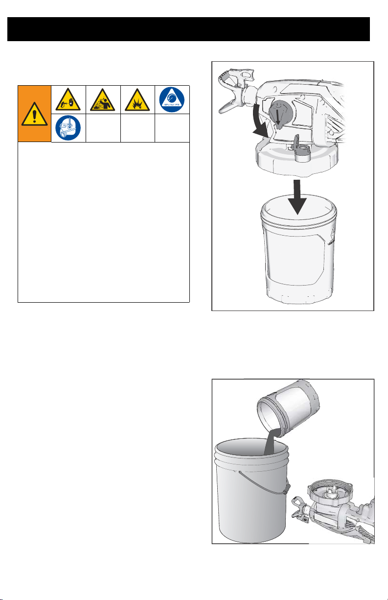
1. Remove cup assembly from the sprayer
by turning and pulling down.
Static Grounding Instructions
, page 27 for additional
It
,
3A4433D 23
Page 24
Common Procedures
ti23676a
ti23361a
ti23383a
ti29719a
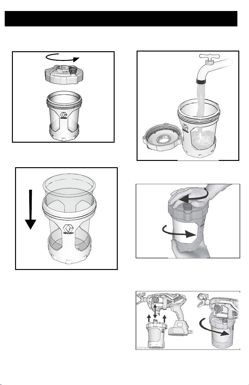
2. Unscrew cup cover from the cup
support.
3. Make certain FlexLiner is in the cup
support.
4. Fill FlexLiner with cleaning fluid. See
Cleaning Fluid Compatibility, page 27
5. Securely tighten cup cover onto cup
support.
.
6. Align VacuValve on cup cover with Prime
Pump/Spray knob. Push cup assembly
onto sprayer and twist to lock.
ti29720a
24 3A4433D
Page 25
Common Procedures
ti29739a
7. Plug sprayer into power source.
8. Make certain the Prime Pump/Spray
knob is in the Prime Pump position
(pointed down). Set speed control to 10.
9. Turn the sprayer upside down and point
the sprayer into a waste pail. Pull the
trigger for three seconds.
10. Turn Prime Pump/Spray knob forward to
SPRAY position. Rotate spray tip 180
degrees to UNCLOG position.
11. While holding the sprayer upside down
point the sprayer into a waste pail. Pull
the trigger for three seconds.
ti29776a
IMPORTANT! For best results, do not spray
more than one cup of water through the tip
while cleaning. If more flushing is needed,
remove the tip from the sprayer to avoid
excessive wear.
12.
Sprayer is now flushed and ready for
use. See Start Up, page 10.
IMPORTANT! The motor has a built-in
feature to protect itself from overuse. If the
motor stops, the thermal switch has tripped.
Do not return sprayer to store. The motor
will operate normally after cooling for 20-30
minutes.
SPRAY UNCLOG
3A4433D 25
ti29740a
Page 26

Reference
ti29772a
412 tip has 8-10 in.
(20-25 cm) fan width.
412 tip has a
0.012 in.
hole size.
Reference
Spray Tip Selection
Spray tips come in a variety of hole sizes for
spraying a range of fluids. Your sprayer
includes a tip for use in most paint spraying
applications. Use the coatings table on page
14 to determine the range of recommended
tip hole sizes for each fluid type. If you need
a tip other than the one supplied, see How to
Spray, page 14.
NOTE: For proper sprayer operation use only
a tip from the same tip family that came with
your sprayer.
Hints:
•
As you spray, the tip wears and
enlarges. Starting with a tip hole size
smaller than the maximum will allow you
to spray within the rated flow capacity of
the sprayer.
• Use larger tip hole sizes with thicker
coatings and smaller tip hole sizes with
thinner coatings.
• Tips wear with use and need periodic
replacement.
• Tip hole size controls flow rate - the
amount of paint that comes out of the
gun.
Fan Width
Fan width is the size of the spray pattern,
which determines the area covered with each
stroke.
Hints:
•
Select a fan width best suited to the
surface being sprayed.
• Wider fans provide better coverage on
broad, open surfaces.
• Narrower fans provide better control on
small, confined surfaces.
Understanding Tip Number
The last three digits of tip part number (i.e.:
) contains information about hole size
xxx412
and fan width on surface when gun is held 12
in. (30.5 cm) from surface being sprayed.
26 3A4433D
First digit when doubled = approximate fan width.
Last two digits = tip hole size in thousands of an inch.
For an 8 to 10 in. (203 to 254 mm) fan width and 0.010
(0.25 mm) hole size, order Part No.
…410.
Page 27

Reference
Cleaning Fluid Compatibility
Oil- or Water-Based Materials
•
When spraying water-based materials,
flush the system thoroughly with water.
• When spraying oil-based materials,
flush the system thoroughly with mineral
spirits or compatible, oil-based flushing
solvent.
• To spray water-based materials after
spraying oil-based materials, flush the
system thoroughly with water first. The
water flowing out of drain tube should
be clear and solvent-free before you
begin spraying the water-based material.
• To spray oil-based materials after
spraying water-based materials, flush
the system thoroughly with mineral spirits or a compatible oil-based flushing
solvent first. The solvent flowing out of
the drain tube should not contain any
water. When flushing with solvents
always follow Static Grounding
Instructions (Oil-Based materials),
page 27.
• To avoid fluid splashing back on your
skin or into your eyes, always aim gun at
inside wall of pail.
Static Grounding Instructions (Oil-Based materials)
The equipment must be grounded to
reduce the risk of static sparking and
electric shock. An electric or static spark
can cause fumes to ignite or explode. An
improper ground can cause electric shock.
A good ground provides an escape wire for
the electric current.
Always use a metal pail for oil-based
materials requiring flushing with compatible
oil-based flushing solvents when sprayer is
flushed or pressure is relieved.
Follow local code. Use only conductive metal
pails, placed on a grounded surface such as
concrete.
Do not place pail on a non-conductive surface
such as paper or cardboard which interrupts
grounding continuity.
3A4433D 27
Page 28

Maintenance
Maintenance
Routine maintenance is important to ensure proper operation of your sprayer.
Activity Interval
Inspect pump filter. Daily or each time you spray
Inspect enclosure vents for blockage.
Inspect pump inlet holes located under pump filter for blockage.
Cleaning Outlet Valves
Dirt and debris in the outlet valve assemblies
may affect sprayer performance and require
cleaning.
1. To clean the three outlet valves, remove
two pump plugs and front valve. Remove
pump plugs with 8mm or 5/16” Allen
wrench.
Do not push outlet valves all the way into
the valve plugs or front valve. If outlet
valves are pushed all the way into the valve
plugs or front valve the sprayer will spray
with reduced performance.
a. Make certain o-rings are on the
2. Clean outlet valve assemblies with warm
water or mineral spirits.
3. Check ball should move freely against
the spring in the retainer.
4. If outlet valve assembly was removed
from the valve plug, assemble as shown.
Leave a space between the end of the
plug or front valve and shoulder on the
outlet valve assembly.
b. Install two pump plugs and front
Daily or each time you spray
Each time the sprayer is cleaned
NOTICE
valve plugs and front valve.
valve. Install pump plugs with 8mm
or 5/16” Allen wrench. Torque outlet
valve and pump plugs, see page 30
for torques.
28 3A4433D
Page 29

Notes
Notes
3A4433D 29
Page 30

Replacement Parts
3
4
1
2
7
Ref. Torque Ref. Torque
10 in-lb (1.1 N•m) 55-65 in-lb (6.2 - 7.3 N•m)
8-10 in-lb (0.9 - 1.1 N•m) 5-7 in-lb (0.6 - 0.8 N•m)
10-15 in-lb (1.1 - 1.7 N•m)
14273
Replacement Parts
30 3A4433D
Page 31

Replacement Parts
Parts List
Ref. Sprayer Name Part # Description
1 All 17P185 Kit, pump assembly includes 4, 9, 11, 25
3
4All17P183 Kit, outlet valve repair includes 3 of 4a, 2 of 4b, 2 of 50, 1 of 51
4a All Outlet valve assembly
4b All Outlet valve plug
9 All 17P098 Prime Pump/Spray valve includes 18, 37
11 All 16Y425 O-ring
12 All 17P176 Kit, Smartcontrol with enclosure includes 31, 34, 7 of 37, 52
13 All 17N515 Lid, cup includes 1 of 19
14
15
16
17 All 17M879 Plug, cup lid, not shipped with sprayer (not shown)
18 All 17M882 Prime Pump/Spray knob
19 All 17P712 VacuValve cap (3-pack)
20
25 All 17P174 Kit, front valve includes 51
29
30
31 All 17P234 Kit, enclosure, cover includes 7 of 37
34 All 17P099 Motor, AC 120V
36 All 17P501 Kit, tip seat and seal (5-pack)
37 All 17R614 Screw, cross-head
37a All 128726 Screw, cross-head
40
50 All 17M394 O-ring
51 All 125119 O-ring
- - - 24D386 Pump Armor, included with sprayer 4 oz (not shown)
- - - 244168 Pump Armor, not shipped with sprayer 8 oz (not shown)
52 All 17P676 Kit, warning labels
53 All
Replacement Danger and Warning labels, tags, and cards are available at no cost.
All 17P554 Filter. pump, 60 mesh, 3 pack
All 17P555 Filter. pump, 100 mesh, 3 pack
All 17A226 FlexLiner, 32 oz. (3-pack)
All 17P212 FlexLiner, 32 oz. (25-pack)
All 17F005 FlexLiner, 42 oz. (3-pack)
All 17P549 FlexLiner, 42 oz. (25-pack)
Ultra, Ultimate 17N392 Support, cup, 32 oz.
TC Pro 16W846 Support, cup, 32 oz.
17P550 Kit, cup support, lid and plug 32 oz. includes 13, 1 of 14, 15,
17P552 Kit, cup support, lid and plug 42 oz. includes 13, 1 of 14, 15,
Ultra 17P659 Kit, label, brand, Ultra
Ultimate 17P661 Kit, label, brand, Ultimate
TC Pro 17P662 Kit, label, brand, TC Pro
Ultra, Ultimate 246215 Guard, spray tip, FFLP
TC Pro 17P574 Guard, spray tip, TCP
Ultra, Ultimate FFLP514 Spray tip, FFLP 514
TC Pro TCP514 Spray tip, TC P514
Ultra, Ultimate
TC Pro
17M883 Case, storage (not shown)
17N194 Case, storage (not shown)
179960 Medical Alert Card, English, Spanish, French (not shown)
17, 1 of 19
17, 1 of 19
(not shown)
3A4433D 31
Page 32
Troubleshooting
844-241-9499
Troubleshooting
Check everything in this Troubleshooting
Table before you bring the sprayer to an
authorized service center.
Sprayer Diagnostics
Problem Cause Solution
Sprayer makes no sound
when trigger is pulled
Diagnostic light does not blink when
the spray is first plugged in. Indicates
no power to the sprayer.
Diagnostic light blinks once when the
sprayer is first plugged in. Indicates
power to the sprayer.
Diagnostic light blinks four times
when the trigger is pulled. Indicates a
locked rotor condition.
Verify power to the sprayer.
Replace
enclosure.
Motor has overheated, wait
20–30 minutes for the motor to
cool.
Motor brushes are worn, replace
motor.
Replace pump and/or motor
assembly.
Smartcontrol with
32 3A4433D
Page 33
Troubleshooting
Problem Cause Solution
Sprayer makes sound but
no material is sprayed
when trigger is pulled
Sprayer is not primed. Prime the pump. See Starting a
Prime Pump/Spray knob is in PRIME
PUMP position.
Spray tip is not in SPRAY position. Turn spray tip to SPRAY
Spray tip is clogged. See Clear Tip Clog, page 16.
Debris in paint. See Strain the Paint, page 10.
Pump filter plugged. See step 16 on page 20
Speed control is set too low. Increase speed until unit sprays.
No or low material in material cup. Refill FlexLiner with material and
Pump has reached the end of its life. Replace pump assembly.
Diagnostic light blinks four times
when the trigger is pulled. Indicates a
locked rotor condition.
New Job, page 10.
Make certain there is only one
FlexLiner in the cup support.
Make certain the cup cover is
properly threaded to the cup
support. If threads are visible
below the cup cover when tight,
fully remove and reinstall to the
cup support so no threads are
visible when tight.
Make certain the cup cover is
tightened to cup support. For
proper sprayer operation lid must
seal tightly with the cup.
Make certain the cup assembly is
properly locked on the sprayer.
Make certain all the air is out of
the FlexLiner and the VacuValve
is properly closed.
Clean VacuValve reservoir and
air hole. See Cleaning
VacuValve, page 21.
Replace VacuValve.
Clean Sprayer. See Cleanup,
page 18.
Outlet valves are not installed
properly. See Cleaning Outlet
Valves, page 28.
Turn Prime Pump/Spray knob
forward to SPRAY position.
position.
prime the pump. See Refilling
FlexLiner, page 13.
Replace pump and/or motor
assembly.
3A4433D 33
Page 34
Troubleshooting
Problem Cause Solution
Sprayer sprays with poor
results
Sprayer runs
intermittently or very slow
Pump will spray paint but
will not spray water
Paint leaks out of the cup
threads.
Spray tip is partially clogged. See Clear Tip Clog, page 16
Spray tip is not in correct position Rotate spray tip to SPRAY
Incorrect spray tip for application of
material.
Spray tip is worn or damaged Replace spray tip. See Spray
Material being sprayed is aerated
because it was shaken.
Material being sprayed is too cold to
spray.
Outlet valves are dirty or worn. Remove two pump plugs and
Pump has reached the end of its life. Replace pump assembly.
Fluid has gotten into the sprayer. Allow the sprayer to dry out.
Pump has reached the end of its life. Replace pump assembly.
Cup not properly seated.
.
position.
Install different size spray tip.
See Tip and Pressure
Selection, page 14.
Tip Installation, page 23.
Do NOT shake material. Stir the
material or check the
manufacturer’s recommendation
for the material being sprayed.
Warm material.
front valve to gain access to the
three outlet valves. Clean outlet
valves. Outlet valves are not
installed properly. See Cleaning
Outlet Valves, page 28.
Replace if necessary.
Replace motor and/or
Smartcontrol with enclosure.
Make certain that there is only
one FlexLiner in cup support.
Make certain the cup cover is
properly threaded to the cup
support. If threads are visible
below the cup support when
tight, fully remove the cup cover
and reinstall to the cup support
so no threads are visible when
tight.
Make certain the cup cover is
tightened to cup support. For
proper sprayer operation lid must
seal tightly with the cup.
Avoid flexing or pushing on the
cup support when you evacuate
the air out of the FlexLiner.
Avoid pulling down on the
FlexLiner when you evacuate the
air out of the FlexLiner.
Make certain there is no damage
to the FlexLiner lip or the cup
cover gasket.
Make certain that the FlexLiner
lip and cup cover gasket is free of
debris and dried paint.
Replace FlexLiner.
34 3A4433D
Page 35
Spray Pattern Diagnostics
Problem Cause Solution
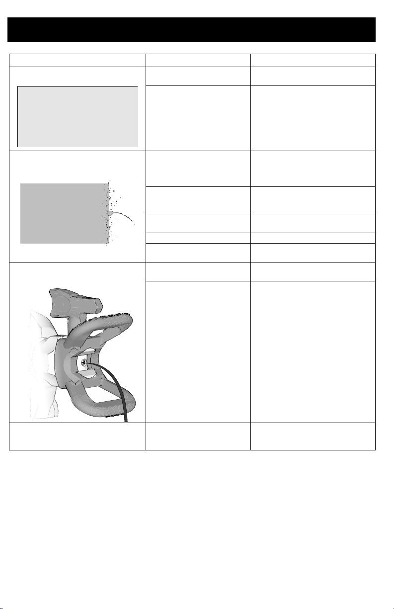
Spray pattern is uneven: Operator is moving too
Spray pattern has tails: Speed control is set too
Spray pattern has
dripping/sagging:
Spray pattern is too narrow: Sprayer is too close to
fast while spraying.
Spray tip is clogged. Unclog spray tip or clean spray
Material difficult to
atomize.
Outlet valves are dirty or
worn.
Pump has reached the end
of its life.
low.
Material may need to be
thinned.
Incorrect spray tip for
application of material.
Material not compatible
with sprayer.
Spray tip is worn or
damaged.
Operator is moving too
slowly while spraying.
Sprayer is too close to
target surface.
Holding trigger while
changing spray direction.
Speed control is set too
high.
Spray tip is worn or
damaged.
target surface.
Incorrect spray tip for
application of material.
Spray tip is worn or
damaged.
Troubleshooting
Slow speed of movement.
tip see Clear Tip Clog, page 16.
Increase speed control until
desired pattern is achieved.
Hold sprayer farther away from
surface.
Switch to different spray tip. See
Tip and Pressure Selection,
page 14.
Remove two pump plugs and
front valve to gain access to the
three outlet valves. Clean outlet
valves. Outlet valves are not
installed properly. See Cleaning
Outlet Valves, page 28.
Replace if necessary.
Replace pump assembly.
Increase speed until desired
pattern is achieved.
Thin material follow paint
manufacturer’s
recommendations.
Install different size spray tip.
See Tip and Pressure
Selection, page 14.
Switch material.
Replace spray tip. See Spray
Tip Installation, page 23.
Move sprayer faster while
spraying.
Move sprayer away from
surface 12 in. (30 cm)
Release trigger when changing
directions.
Decrease speed until desired
pattern is achieved.
Replace spray tip. See Spray
Tip Installation, page 23.
Move sprayer away from
surface 12 in. (30 cm)
Install different size spray tip.
See Tip and Pressure
Selection, page 14.
Replace spray tip. See Spray
Tip Installation, page 23.
3A4433D 35
Page 36
Troubleshooting
ti30016a
Problem Cause Solution
Spray pattern is too wide: Sprayer is too far away
from target surface.
Incorrect spray tip for
application of material.
Move sprayer closer to surface.
Install different size spray tip.
See Tip and Pressure
Selection, page 14.
Spray pattern “spits” at the
beginning or end of pattern:
Spray tip continues to drip or ooze
material after trigger is released:
Material leaks around spray tip
guard or spray tip handle
Excess material has
accumulated on spray tip
guard assembly or spray
tip is partially clogged.
Spray tip not inserted
completely into spray tip
guard.
Spray tip is worn. Replace spray tip. See Spray
Sprayer is dirty Flush sprayer.
Front valve has reached
the end of its life.
Spray tip is worn. Replace spray tip. See Spray
Spray tip not inserted
completely into spray tip
guard.
Spray tip seal and seat are
damaged or not properly
installed.
Clean spray tip guard. See
Clear Tip Clog, page 16.
See Spray Tip Installation,
page 23.
Tip Installation, page 23.
Replace front valve assembly.
Tip Installation, page 23.
See Spray Tip Installation,
page 23.
See Spray Tip Installation,
page 23.
36 3A4433D
Page 37

Technical Specifications
Technical Specifications
HandHeld Sprayer
U.S. Metric
Max Working Pressure 2000 psi 14 MPa, 138bar
Maximum Amperage 3.6 Amps 3.6 Amps
Weight
Dimensions:
Length
Width
Height
Storage Temperature Range 32° to 113° F 0° to 45° C
Operating Temperature Range 40° to 90° F 4° to 32° C
Storage Humidity Range 0% to 95% relative humidity, non-condensing
Sound Pressure Level
Sound Power Level
Vibration level (measured in
accordance with EN50580:2012)
Power Cord 18 AWG, 3-wire
Length
Electrical Power Requirement 120 Vac, 60 Hz, 15A, 1 Ø
Maximum tip orifice
† 90.0 dBa, Uncertainty K = 0.5 dBa
Uncertainty = 0.3 ft/s
Pump damage will occur if fluid freezes in pump.
Damage to plastic parts may result if impact occurs in low temperature conditions.
Changes in paint viscosity at very low or very high temperatures can affect sprayer
performance.
† All readings were taken within the priming mode at the assumed operator position. Sound
power levels were tested to ISO 3741 at 3.3 feet (1m).
4.6 lb 2.1 kg
14.0 in. 36.1 cm
5 in. 12.7 cm
10.5 in. 26.7 cm
85.1 dBa
Vibration total value
= 21.5 ft/s
a
h
18 in. 45.7 cm
0.016 in. 0.41 mm
2
2
Vibration total value
Uncertainty = 0.1 m/s
ah = 6.5 m/s
2
1.0 mm
, 3-wire
2
2
3A4433D 37
Page 38

Notes
Notes
38 3A4433D
Page 39

Graco Limited Warranty
Graco Limited Warranty
Graco warrants all equipment referenced in this document which is manufactured by Graco and bearing
its name to be free from defects in material and workmanship on the date of sale to the original purchaser
for use. With the exception of any special, extended, or limited warranty published by Graco, Graco will,
for a period of twelve months from the date of sale, repair or replace any part of the equipment
determined by Graco to be defective. This warranty applies only when the equipment is installed,
operated and maintained in accordance with Graco’s written recommendations.
This warranty does not cover, and Graco shall not be liable for general wear and tear, or any malfunction,
damage or wear caused by faulty installation, misapplication, abrasion, corrosion, inadequate or
improper maintenance, negligence, accident, tampering, or substitution of non-Graco component parts.
Nor shall Graco be liable for malfunction, damage or wear caused by the incompatibility of Graco
equipment with structures, accessories, equipment or materials not supplied by Graco, or the improper
design, manufacture, installation, operation or maintenance of structures, accessories, equipment or
materials not supplied by Graco.
This warranty is conditioned upon the prepaid return of the equipment claimed to be defective to an
authorized Graco distributor for verification of the claimed defect. If the claimed defect is verified, Graco
will repair or replace free of charge any defective parts. The equipment will be returned to the original
purchaser transportation prepaid. If inspection of the equipment does not disclose any defect in material
or workmanship, repairs will be made at a reasonable charge, which charges may include the costs of
parts, labor, and transportation.
THIS WARRANTY IS EXCLUSIVE, AND IS IN LIEU OF ANY OTHER WARRANTIES, EXPRESS OR
IMPLIED, INCLUDING BUT NOT LIMITED TO WARRANTY OF MERCHANTABILITY OR WARRANTY
OF FITNESS FOR A PARTICULAR PURPOSE.
Graco’s sole obligation and buyer’s sole remedy for any breach of warranty shall be as set forth above.
The buyer agrees that no other remedy (including, but not limited to, incidental or consequential
damages for lost profits, lost sales, injury to person or property, or any other incidental or consequential
loss) shall be available. Any action for breach of warranty must be brought within two (2) years of the
date of sale.
GRACO MAKES NO WARRANTY, AND DISCLAIMS ALL IMPLIED WARRANTIES OF
MERCHANTABILITY AND FITNESS FOR A PARTICULAR PURPOSE, IN CONNECTION WITH
ACCESSORIES, EQUIPMENT, MATERIALS OR COMPONENTS SOLD BUT NOT MANUFACTURED
BY GRACO. These items sold, but not manufactured by Graco (such as electric motors, switches, hose,
etc.), are subject to the warranty, if any, of their manufacturer. Graco will provide purchaser with
reasonable assistance in making any claim for breach of these warranties.
In no event will Graco be liable for indirect, incidental, special or consequential damages resulting from
Graco supplying equipment hereunder, or the furnishing, performance, or use of any products or other
goods sold hereto, whether due to a breach of contract, breach of warranty, the negligence of Graco, or
otherwise.
FOR GRACO CANADA CUSTOMERS
The Parties acknowledge that they have required that the present document, as well as all documents,
notices and legal proceedings entered into, given or instituted pursuant hereto or relating directly or
indirectly hereto, be drawn up in English. Les parties reconnaissent avoir convenu que la rédaction du
présente document sera en Anglais, ainsi que tous documents, avis et procédures judiciaires exécutés,
donnés ou intentés, à la suite de ou en rapport, directement ou indirectement, avec les procédures
concernées.
3A4433D 39
Page 40

Graco Information
For the latest information about Graco products, visit www.graco.com.
For patent information, see www.graco.com/patents.
TO PLACE AN ORDER, contact your Graco distributor or call 1-888-541-9788 to identify the nearest
distributor.
All written and visual data contained in this document reflects the latest product information available at
Graco reserves the right to make changes at any time without notice.
Original instructions. This manual contains English. MM 3A4433
the time of publication.
Graco Headquarters: Minneapolis
International Offices: Belgium, China, Japan, Korea
GRACO INC. AND SUBSIDIARIES • P.O. BOX 1441 • MINNEAPOLIS MN 55440-1441 • USA
Copyright 2016, Graco Inc. All Graco manufacturing locations are registered to ISO 9001.
www.graco.com
Revision D, December 2017
 Loading...