

Page 1

B
OM−01228−05
August 9, 2006
Rev. B 07-15-08
INSTALLATION, OPERATION,
AND MAINTENANCE MANUAL
WITH PARTS LIST
UNIT SERIES PUMP
MODEL
UNIT 608
tankleenor
r
THE GORMAN-RUPP COMPANY MANSFIELD, OHIO
www.grpumps.com
GORMAN-RUPP OF CANADA LIMITED ST. THOMAS, ONTARIO, CANADA Printed in U.S.A.
2006 The Gorman-Rupp Company
Page 2

Register your new
Gorman-Rupp pump online at
www.grpumps.com/register.
Valid serial number and e-mail address required.
RECORD YOUR PUMP MODEL AND SERIAL NUMBER
Please record your pump model and serial number in the
spaces provided below. Your Gorman-Rupp distributor
needs this information when you require parts or service.
Pump Model:
Serial Number:
Page 3

TABLE OF CONTENTS
INTRODUCTION PAGE I − 1. . . . . . . . . . . . . . . . . . . . . . . . . . . . . . . . . . . . . . . . . . . . . . . . .
SAFETY - SECTION A PAGE A − 1. . . . . . . . . . . . . . . . . . . . . . . . . . . . . . . . . . . . . . . . . . . .
INSTALLATION − SECTION B PAGE B − 1. . . . . . . . . . . . . . . . . . . . . . . . . . . . . . . . . . . .
Pump Dimensions PAGE B − 1. . . . . . . . . . . . . . . . . . . . . . . . . . . . . . . . . . . . . . . . . . . . . . . . . . . . .
PREINSTALLATION INSPECTION PAGE B − 1. . . . . . . . . . . . . . . . . . . . . . . . . . . . . . . . . . . . . . . . . . . .
UNIT INSTALLATION PAGE B − 2. . . . . . . . . . . . . . . . . . . . . . . . . . . . . . . . . . . . . . . . . . . . . . . . . . . . . . .
Lifting PAGE B − 2. . . . . . . . . . . . . . . . . . . . . . . . . . . . . . . . . . . . . . . . . . . . . . . . . . . . . . . . . . . . . . . . .
Mounting PAGE B − 2. . . . . . . . . . . . . . . . . . . . . . . . . . . . . . . . . . . . . . . . . . . . . . . . . . . . . . . . . . . . .
Specifications PAGE B − 2. . . . . . . . . . . . . . . . . . . . . . . . . . . . . . . . . . . . . . . . . . . . . . . . . . . . . . . . .
Positioning Unit and Setup PAGE B − 2. . . . . . . . . . . . . . . . . . . . . . . . . . . . . . . . . . . . . . . . . . . . . .
Line Configuration PAGE B − 5. . . . . . . . . . . . . . . . . . . . . . . . . . . . . . . . . . . . . . . . . . . . . . . . . . . . . .
Hose Connections PAGE B − 5. . . . . . . . . . . . . . . . . . . . . . . . . . . . . . . . . . . . . . . . . . . . . . . . . . . . .
SUCTION LINES PAGE B − 6. . . . . . . . . . . . . . . . . . . . . . . . . . . . . . . . . . . . . . . . . . . . . . . . . . . . . . . . . . .
Suction Line Positioning PAGE B − 6. . . . . . . . . . . . . . . . . . . . . . . . . . . . . . . . . . . . . . . . . . . . . . . .
DISCHARGE LINES PAGE B − 6. . . . . . . . . . . . . . . . . . . . . . . . . . . . . . . . . . . . . . . . . . . . . . . . . . . . . . . .
Siphoning PAGE B − 6. . . . . . . . . . . . . . . . . . . . . . . . . . . . . . . . . . . . . . . . . . . . . . . . . . . . . . . . . . . . .
Valves PAGE B − 6. . . . . . . . . . . . . . . . . . . . . . . . . . . . . . . . . . . . . . . . . . . . . . . . . . . . . . . . . . . . . . . .
OPERATION − SECTION C PAGE C − 1. . . . . . . . . . . . . . . . . . . . . . . . . . . . . . . . . . . . . .
PRIMING PAGE C − 1. . . . . . . . . . . . . . . . . . . . . . . . . . . . . . . . . . . . . . . . . . . . . . . . . . . . . . . . . . . . . . . . .
Leakage PAGE C − 1. . . . . . . . . . . . . . . . . . . . . . . . . . . . . . . . . . . . . . . . . . . . . . . . . . . . . . . . . . . . . .
Liquid Temperature And Overheating PAGE C − 2. . . . . . . . . . . . . . . . . . . . . . . . . . . . . . . . . . . . .
OPERATION PAGE C − 2. . . . . . . . . . . . . . . . . . . . . . . . . . . . . . . . . . . . . . . . . . . . . . . . . . . . . . . . . . . . . .
STOPPING PAGE C − 3. . . . . . . . . . . . . . . . . . . . . . . . . . . . . . . . . . . . . . . . . . . . . . . . . . . . . . . . . . . . . . . .
Cold Weather Preservation PAGE C − 3. . . . . . . . . . . . . . . . . . . . . . . . . . . . . . . . . . . . . . . . . . . . . .
TROUBLESHOOTING − SECTION D PAGE D − 1. . . . . . . . . . . . . . . . . . . . . . . . . . . . . .
PREVENTIVE MAINTENANCE PAGE D − 3. . . . . . . . . . . . . . . . . . . . . . . . . . . . . . . . . . . . . . . . . . . . . . .
PUMP MAINTENANCE AND REPAIR - SECTION E PAGE E − 1. . . . . . . . . . . . . . . . .
STANDARD PERFORMANCE PAGE E − 1. . . . . . . . . . . . . . . . . . . . . . . . . . . . . . . . . . . . . . . . . . . . . . .
PARTS LISTS:
UNIT 608 tankleenor PAGE E − 3. . . . . . . . . . . . . . . . . . . . . . . . . . . . . . . . . . . . . . . . . . . . . . . . . .
PPO (UNIT 608) PAGE E − 5. . . . . . . . . . . . . . . . . . . . . . . . . . . . . . . . . . . . . . . . . . . . . . . . . . . . . . . .
13559 Eductor Valve Assembly PAGE E − 7. . . . . . . . . . . . . . . . . . . . . . . . . . . . . . . . . . . . . . . . . .
41331−009 Reel Assembly PAGE E − 9. . . . . . . . . . . . . . . . . . . . . . . . . . . . . . . . . . . . . . . . . . . . . .
46341−428 Hose Assembly PAGE E − 11. . . . . . . . . . . . . . . . . . . . . . . . . . . . . . . . . . . . . . . . . . . . .
46312−009 Standpipe Assembly PAGE E − 12. . . . . . . . . . . . . . . . . . . . . . . . . . . . . . . . . . . . . . . .
PUMP AND SEAL DISASSEMBLY AND REASSEMBLY PAGE E − 13. . . . . . . . . . . . . . . . . . . . . . . . .
Pump Disassembly PAGE E − 13. . . . . . . . . . . . . . . . . . . . . . . . . . . . . . . . . . . . . . . . . . . . . . . . . . . . .
Impeller Removal PAGE E − 13. . . . . . . . . . . . . . . . . . . . . . . . . . . . . . . . . . . . . . . . . . . . . . . . . . . . . .
Seal Removal and Disassembly PAGE E − 14. . . . . . . . . . . . . . . . . . . . . . . . . . . . . . . . . . . . . . . . . .
Seal Reassembly and Installation PAGE E − 14. . . . . . . . . . . . . . . . . . . . . . . . . . . . . . . . . . . . . . . .
Impeller Installation PAGE E − 15. . . . . . . . . . . . . . . . . . . . . . . . . . . . . . . . . . . . . . . . . . . . . . . . . . . . .
i
Page 4

TABLE OF CONTENTS
(continued)
Pump Reassembly PAGE E − 16. . . . . . . . . . . . . . . . . . . . . . . . . . . . . . . . . . . . . . . . . . . . . . . . . . . . .
Final Pump Assembly PAGE E − 16. . . . . . . . . . . . . . . . . . . . . . . . . . . . . . . . . . . . . . . . . . . . . . . . . .
LUBRICATION PAGE E − 16. . . . . . . . . . . . . . . . . . . . . . . . . . . . . . . . . . . . . . . . . . . . . . . . . . . . . . . . . . . . .
Seal Assembly PAGE E − 16. . . . . . . . . . . . . . . . . . . . . . . . . . . . . . . . . . . . . . . . . . . . . . . . . . . . . . . . .
EDUCTOR VALVE DISASSEMBLY AND REASSEMBLY PAGE E − 17. . . . . . . . . . . . . . . . . . . . . . . . .
Eductor Valve Disassembly PAGE E − 17. . . . . . . . . . . . . . . . . . . . . . . . . . . . . . . . . . . . . . . . . . . . . .
Eductor Valve Reassembly PAGE E − 17. . . . . . . . . . . . . . . . . . . . . . . . . . . . . . . . . . . . . . . . . . . . . .
HOSE AND REEL DISASSEMBLY AND REASSEMBLY PAGE E − 17. . . . . . . . . . . . . . . . . . . . . . . . .
Hose Disassembly PAGE E − 17. . . . . . . . . . . . . . . . . . . . . . . . . . . . . . . . . . . . . . . . . . . . . . . . . . . . .
Reel Disassembly PAGE E − 18. . . . . . . . . . . . . . . . . . . . . . . . . . . . . . . . . . . . . . . . . . . . . . . . . . . . . .
Reel Reassembly PAGE E − 18. . . . . . . . . . . . . . . . . . . . . . . . . . . . . . . . . . . . . . . . . . . . . . . . . . . . . .
Hose Reassembly PAGE E − 19. . . . . . . . . . . . . . . . . . . . . . . . . . . . . . . . . . . . . . . . . . . . . . . . . . . . . .
STANDPIPE DISASSEMBLY AND REASSEMBLY PAGE E − 19. . . . . . . . . . . . . . . . . . . . . . . . . . . . . .
Standpipe Disassembly PAGE E − 19. . . . . . . . . . . . . . . . . . . . . . . . . . . . . . . . . . . . . . . . . . . . . . . . .
ii
Page 5
UNIT SERIES
OM−01228
INTRODUCTION
Thank You for purchasing a Gorman-Rupp pump.
Read this manual carefully to learn how to safely
install and operate your pump. Failure to do so
could result in personal injury or damage to the
pump.
The Unit 608 tankleenor is designed to permit
quick, efficient cleaning of below-ground petroleum sotrage tanks without disturbing the product
or disrupting service. The cleaning system is capable of extracting gel precipitates, rust, water or other contaminants that present problems in fuel storage.
The tankleenor incorporates portable, lightweight components allowing one man operation.
The system utilizes an 0-Series self-priming centrifugal pump that is close-coupled to a single-phase
explosion-proof electric motor equipped with 50
feet of grounded power cable.
If there are any questions regarding the pump or
its application which are not covered in this manual or in other literature accompanying this unit,
please contact your Gorman-Rupp distributor, or:
The Gorman-Rupp Company
P.O. Box 1217
Mansfield, Ohio 44901−1217
Phone: (419) 755−1011
or:
Gorman-Rupp of Canada Limited
70 Burwell Road
St. Thomas, Ontario N5P 3R7
Phone: (519) 631−2870
For information or technical assistance on the electric motor, contact the motor manufacturer’s local
dealer or representative.
Because pump installations are seldom identical,
this manual cannot possibly provide detailed instructions and precautions for every aspect of
each specific application. Therefore, it is the responsibility of the owner/installer of the pump to
ensure that applications not addressed in this
manual are performed only after establishing that
neither operator safety nor pump integrity are compromised by the installation. Pumps and related
equipment must be installed and operated according to all national, local and industry standards.
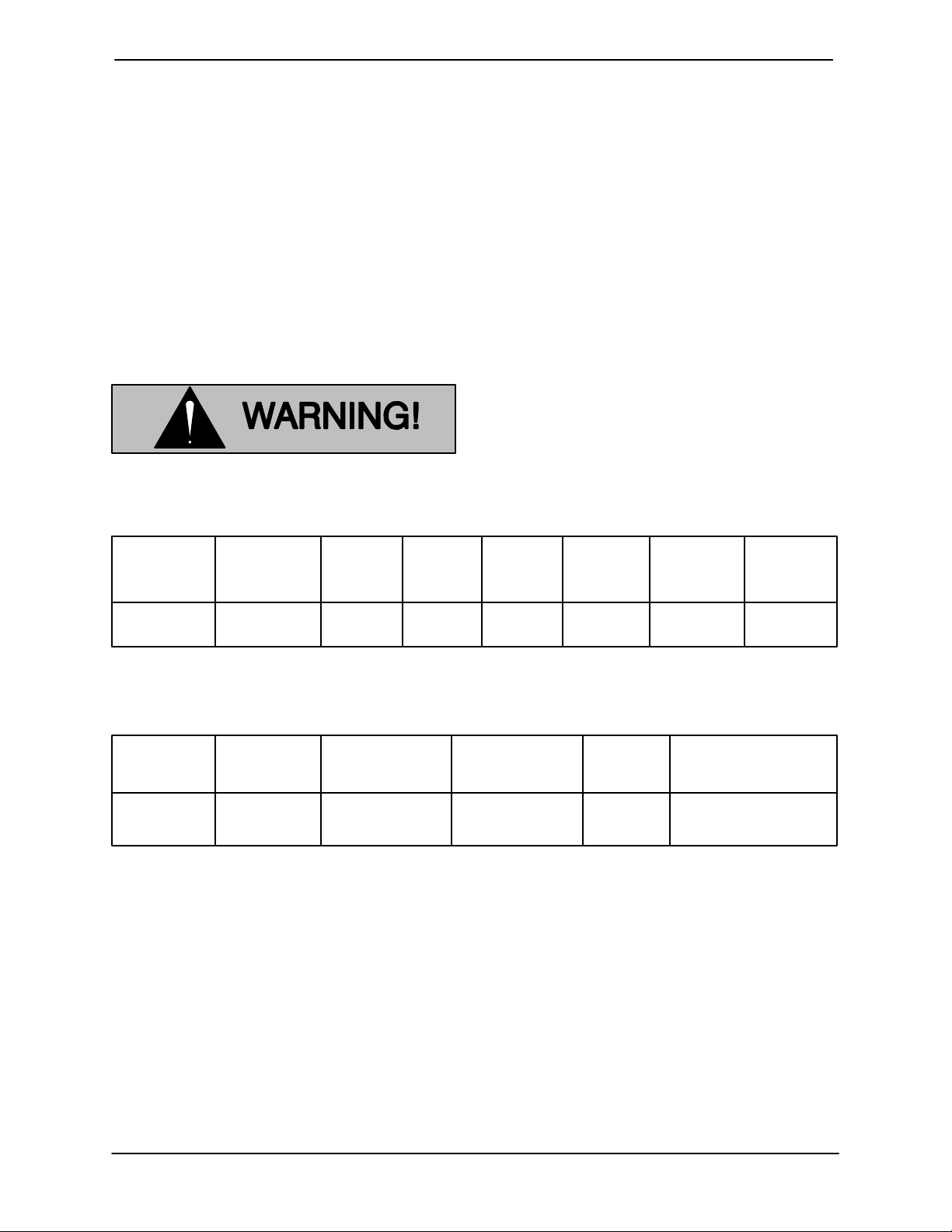
The following are used to alert maintenance personnel to procedures which require special attention, to those which could damage equipment, and
to those which could be dangerous to personnel:
Immediate hazards which WILL result in
severe personal injury or death. These
instructions describe the procedure required and the injury which will result
from failure to follow the procedure.
Hazards or unsafe practices which
COULD result in severe personal injury
or death. These instructions describe
the procedure required and the injury
which could result from failure to follow
the procedure.
Hazards or unsafe practices which COULD
result in minor personal injury or product
or property damage. These instructions
describe the requirements and the possible damage which could result from failure
to follow the procedure.
NOTE
Instructions to aid in installation, operation,and
maintenance, or which clarify a procedure.
PAGE I − 1INTRODUCTION
Page 6
UNIT SERIES
SAFETY - SECTION A
This information applies to operation
and maintenance of the UNIT 608 tankleenorr. Refer to the manual accompanying the electric motor before attempting to begin operation.
Because pump installations are seldom
identical, this manual cannot possibly
provide detailed instructions and precautions for each specific application.
Therefore, it is the owner/installer’s responsibility to ensure that applications
not addressed in this manual are performed only after establishing that neither operator safety nor pump integrity
are compromised by the installation.
OM−01228
Before operating or servicing the pump,
be certain proper safety practices are
followed. Provide adequate ventilation,
prohibit smoking, wear static-resistant
clothing and shoes. Clean up all fuel
spills immediately after occurrence.
Connect the ground wire to the tank fill
pipe or other ground connection before
operating the unit. Static electric buildup could develop during cleaning operation, causing hazardous sparks.
Before attempting to open or service the
pump:
1. Familiarize yourself with this manual.
2. Unplug the motor to ensure that
the pump will remain inoperative.
3. Allow the pump to completely cool
if overheated.
4. Check the temperature before
opening any covers, plates, or
plugs.
5. Vent the pump slowly and cautiously.
6. Drain the pump.
This pump is designed to handle water,
gasoline or other petroleum products.
Do not attempt to pump corrosive or
highly volatile liquids which may damage the pump or endanger personnel as
a result of pump failure.
Do not operate the pump against a
closed eductor control valve for long
periods of time. This could bring the liquid to a boil, build pressure, and cause
the pump casing to rupture or explode.
Overheating may produce dangerous
fumes. Use extreme caution when venting the pump, or when removing covers,
plates, plugs or fittings.
Overheated pumps can cause severe
burns and injury. If overheating of the
pump occurs:
1. Stop the pump immediately.
2. Allow the pump to completely cool
if overheated.
3. Refer to instructions in this manual
before re-starting the pump.
PAGE A − 1SAFETY
Page 7
UNIT SERIESOM−01228
The electrical power used to operate
this unit is high enough to cause injury
or death to personnel. Connect the electrical plug to a grounded power supply;
never use gas piping as an electrical
ground. Be sure the power supply is of
the correct voltage and phase. Do not
run the motor if the power supply is not
within acceptable limits. If a circuit
breaker or fuse is tripped, examine and
correct the problem before re-starting
the unit.
Inspect the suction hose regularly for
cuts, punctures or severe abrasion before operation. Replace the entire hose
assembly if there is any possibility of
leakage or exposure of the integral
spring steel strap inside the hose.
Never attempt to change the electrical
plug or alter the length of the power cord
with a splice. Equipment failure or personal injury could result if all connections are not waterproof and compatible
with the current used.
PAGE A − 2 SAFETY
Page 8
UNIT SERIES OM−01228
INSTALLATION − SECTION B
Review all SAFETY information in Section A.
Since pump installations are seldom identical, this
section offers only general recommendations and
practices required to inspect, position, and arrange the pump and piping.
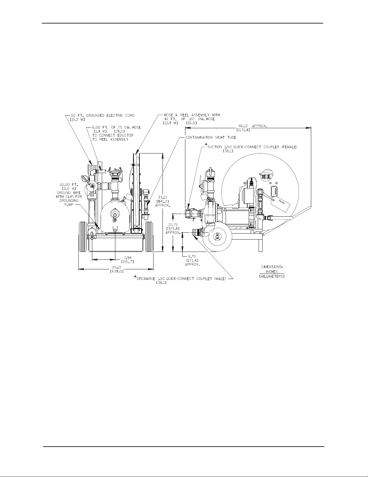
OUTLINE DRAWING
Pump Dimensions
See Figure 1 for the approximate physical dimensions of this pump.
Figure 1. Pump Model UNIT 608
PREINSTALLATION INSPECTION
The pump assembly was inspected and tested before shipment from the factory. Before installation,
inspect the unit for damage which may have occurred during shipment. Check as follows:
a. Inspect the pump, reel assembly, hose and
motor for cracks, dents, damaged threads,
and other obvious damage.
b. Check for and tighten loose attaching hard-
ware. Since gaskets tend to shrink after drying, check for loose hardware at mating surfaces.
c. Carefully read all tags, decals, and markings
on the unit, and perform all duties indicated.
d. If the pump and motor have been stored for
more than 12 months, some of the compo-
nents or lubricants may have exceeded their
maximum shelf life. These must be inspected
or replaced to ensure maximum pump service.
e. Check to ensure the following standard
equipment items are included with the pump
assembly:
Detachable reel assembly.
42 foot long hydrocarbon-resistant hose.
8 foot long connector hose.
15 foot long suction and discharge hose.
12 foot long stainless steel standpipe.
10 foot long ground wire.
If the maximum shelf life has been exceeded, or if
anything appears to be abnormal, contact your
PAGE B − 1INSTALLATION
Page 9
OM−01228 UNIT SERIES
Gorman-Rupp distributor or the factory to determine the repair or updating policy. Do not put the
pump into service until appropriate action has
been taken.
UNIT INSTALLATION
Lifting
This unit is mounted on a two-wheel moveable
base. It weighs approximately 260 pounds (118 kilograms) including suction and discharge hoses
and the standpipe. If it is necessary to lift the unit,
use lifting equipment with a capacity of 5 times the
weight of the unit to ensure safe lifting.
Use lifting and moving equipment in
Table 1. Pump Specifications
good repair and with adequate capacity
to prevent injuries to personnel or damage to equipment.
Mounting
Locate the pump in an accessible place as close as
practical to the liquid being pumped. Level mounting is essential for proper operation.
The pump may have to be supported or shimmed
to provide for level operation or to eliminate vibration.
Specifications
See Table 1 for typical pump specifications.
Pump
Model
02D3 115/230 1 1 3450 60 Hz 1−1/2" 1−1/2"
See Table 1 for typical pump specifications.
Power
Cable
50 Ft.
(15,2 M.)
Positioning Unit and Setup
Figure 2 shows a typical installation of the tankleenor system.
Voltage Phase Horse-
power
Table 2. Unit Specifications
Reel
Assembly
42 Ft.
(12,8 M.)
Suction
Hose
1−1/2" x 15 Ft.
38,1 MM x 4,6 M
Motor
RPM
Discharge
Hose
1−1/2" x 15 Ft.
38,1 MM x 4,6 M
Cycle Suction
Coupler
Ground
Wire
10 Ft.
(3,1 M.)
Standpipe Length
(Min) − (Max)
7.25 Ft. − 12 Ft.
2,2 M − 3,7 M
Discharge
Coupler
PAGE B − 2 INSTALLATION
Page 10
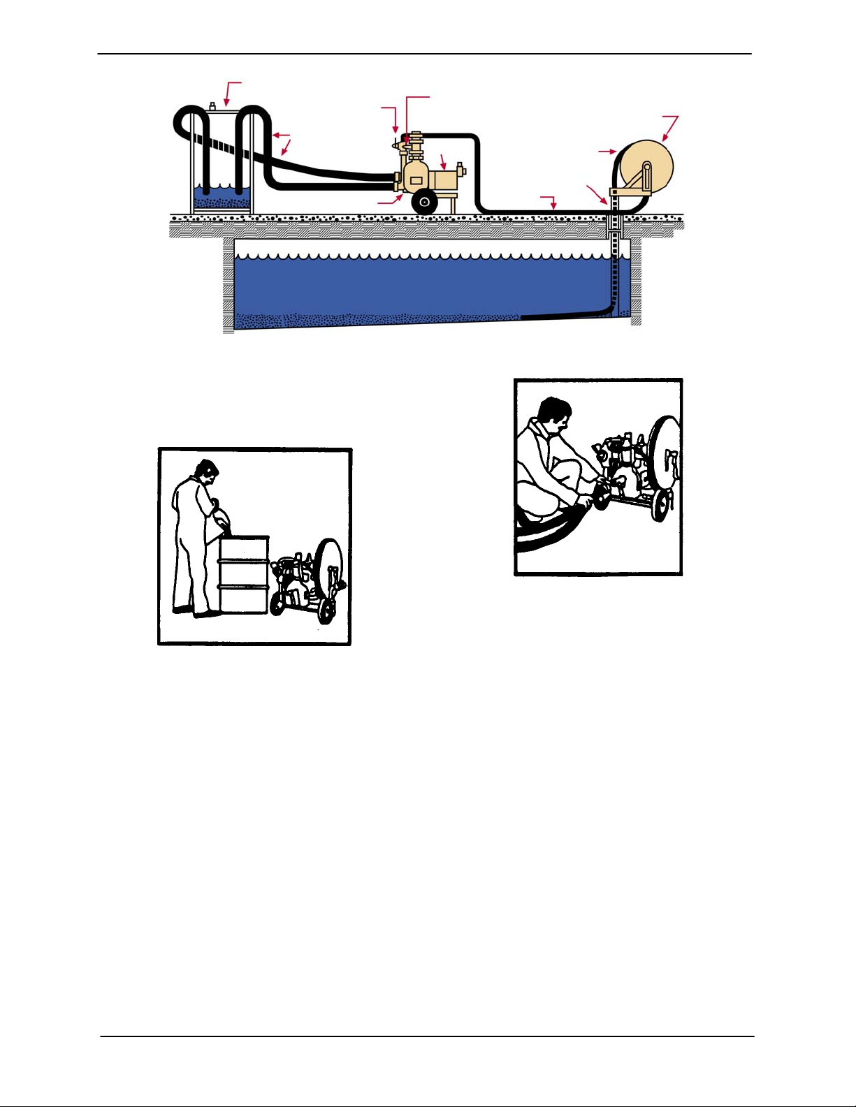
UNIT SERIES OM−01228
CONTAMINANT TANK
(USER SUPPLIED)
DIVERTER VALVE
SUCTION/DISCHARGE RECIRCULATION HOSES
PUMP
TANK
EDUCTOR
MOTOR
STANDPIPE
(GUIDE TUBE)
RETURN
HOSE
REEL ASSEMBLY
CLEANOUT
HOSE
Figure 2. Typical Installation
Perform the following steps, which are illustrated
by Figures 3 through 10, to set up the tankleenor
system for operation.
Figure 3.
See Figure 3 and fill a 55 gallon (208 L) drum (not
supplied) or other ventilated container with
approximately 20 gallons (76 L) of operating liquid
(water). Depending on the size and contamination
of the tank being cleaned, more than one drum
may be required.
Figure 4.
See Figure 4 and install the quick-connect fittings
on the suction and discharge hoses to the eductor
discharge and pump suction. Submerge the other
ends of the hoses in the drum containing the operating liquid (shown in Figure 2).
PAGE B − 3INSTALLATION
Page 11
OM−01228 UNIT SERIES
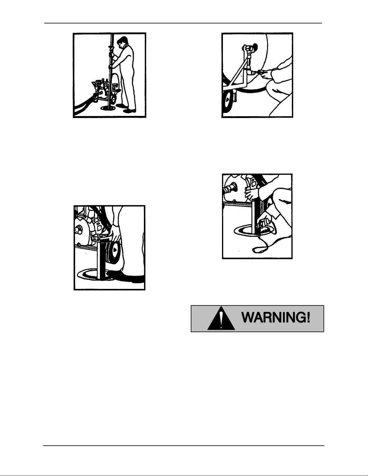
Figure 7.
Figure 5.
See Figure 7 and position the pump close to the
reel assembly and attach the 8-foot hose from the
See Figure 5 and lower the telescopic standpipe
through the tank fill pipe until it reaches the bottom
of the tank. Adjust the length of the standpipe as
necessary.
top of the eductor to the hose reel.
Figure 6.
See Figure 6 and remove the hose reel assembly
from the pump base and attach it to the standpipe.
Secure it in place with the spring clip on the reel assembly. Align the reel assembly with the direction
of the first cleaning path (see OPERATION, Sec-
tion C).
Figure 8.
See Figure 8 and attach the unit ground wire clip to
the tank fill pipe or other ground connection.
Connect the ground wire to the tank fill
pipe or other ground connection before
operating the unit. Static electric build-
up could develop during the cleaning
operation causing hazardous sparks.
PAGE B − 4 INSTALLATION
Page 12
UNIT SERIES OM−01228
run the motor if the power supply is not
within acceptable limits. If a circuit
breaker or fuse is tripped, examine and
correct the problem before re-starting
the unit.
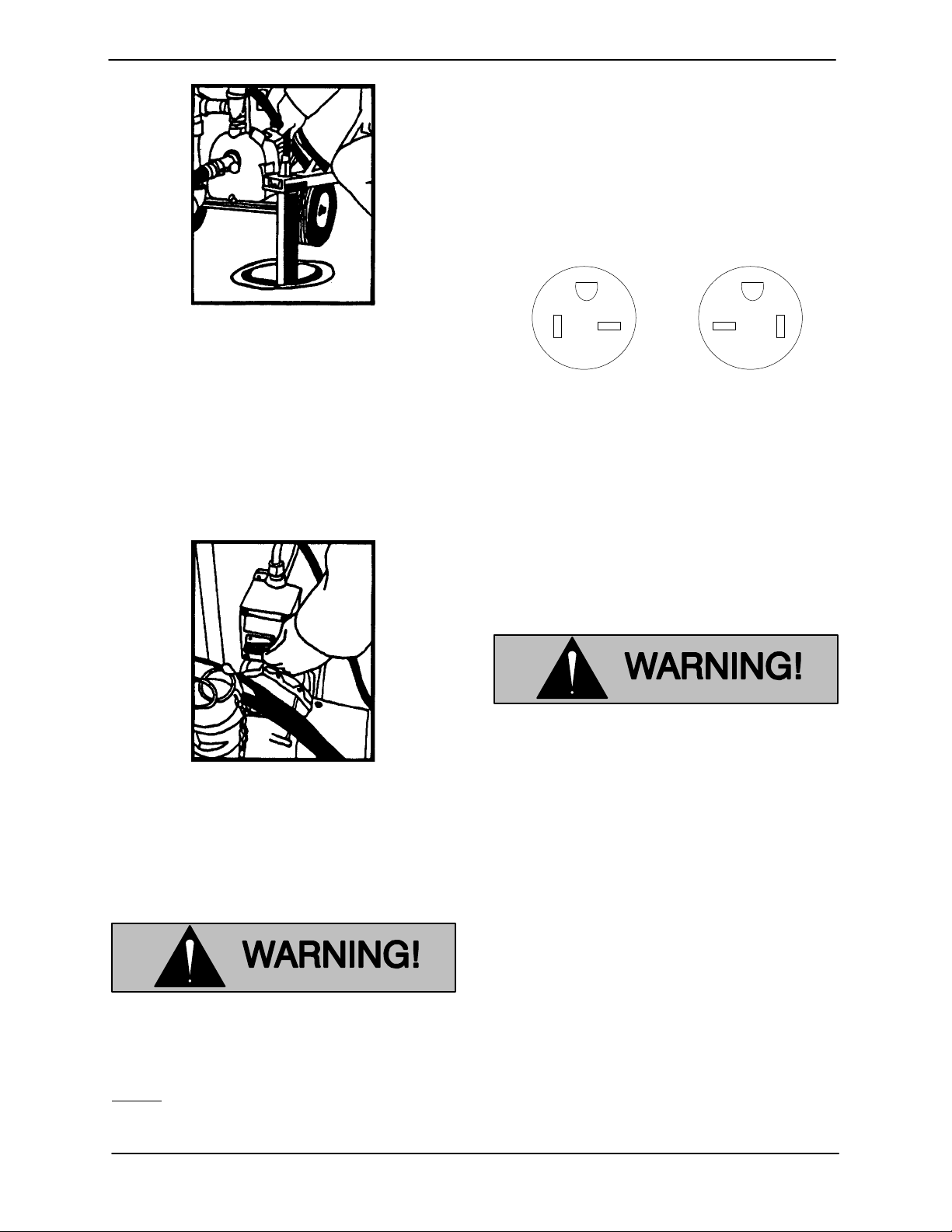
Figure 9.
See Figure 9 and remove the clip that holds the
hose assembly on the reel and insert the nozzle
into the standpiipe. Push the hose down the standpipe until a slight resistance it felt. This occurs
when the suction nozzle travels over the rollers at
the end of the standpipe.
Figure 10.
See Figure 10 and make sure the motor switch is
OFF. Plug the power cable into a 20 amp/120 volt
grounded outlet.
G
Figure 11.
This pump is furnished with a grounded, 20
amp/120 Volt electrical plug as required by the Na-
tional Electric Code (see Figure 11). No cord or
plug substitution is authorized by the Gorman-
Rupp Company.
G
PlugReceptacle
Never attempt to change the electrical
plug or alter the length of the power cord
with a splice. Equipment failure or per-
sonal injury could result if all connec-
tions are not waterproof and compatible
with the electrical current used.
Refer to OPERATION, Section C before starting
the pump.
The electrical power used to operate
this unit is high enough to cause injury
or death to personnel. Connect the electrical plug to a grounded power supply;
never use gas piping as an electrical
ground. Be sure the power supply is of
the correct voltage and phase. Do not
Line Configuration
Keep suction and discharge lines as straight as
possible to minimize friction losses.
Hose Connections
Check all hose and pump connections to be sure
the quick-connect couplers and joints are com-
pletely sealed. Hose lines may have to be sup-
ported and secured when filled and operated un-
der pressure.
PAGE B − 5INSTALLATION
Page 13

OM−01228 UNIT SERIES
SUCTION LINES
Position the suction hose as far away as possible
from the discharge hose. The two hoses must be
on opposite sides of the drum.
Suction Line Positioning
The depth of submergence of the suction line is
critical to efficient pump operation. Figure 12
shows recommended minimum submergence vs.
velocity.
NOTE
The pipe submergence required may be reduced
by installing a standard pipe increaser fitting at the
end of the suction line. The larger opening size will
reduce the inlet velocity. Calculate the required
submergence using the following formula based
on the increased opening size (area or diameter).
Figure 12. Recommended Minimum Suction Line Submergence vs. Velocity
DISCHARGE LINES
Siphoning
Do not terminate the discharge line at a level lower
than that of the liquid being pumped. Otherwise, a
siphoning action causing damage to the pump
could result.
shutoff of the system. Make sure this valve is in the
shutoff position after turning the pump off.
If the eductor valve is not in the shutoff
position when turning the pump off, a si-
Valves
This unit is equipped with an eductor control valve
on the discharge side of the pump. The eductor
has a 3-position valve for vacuum, backflush or
PAGE B − 6 INSTALLATION
phoning action could be created, draining
the pump casing, the suction and dis-
charge lines, and the contaminated liquid
in the drum back into the tank.
Page 14

UNIT SERIES
OPERATION − SECTION C
Review all SAFETY information in Section A.
Follow the instructions on all tags, labels and
decals attached to the pump.
This pump is designed to handle water,
gasoline or other petroleum products.
Do not attempt to pump corrosive or
highly volatile liquids which may damage the pump or endanger personnel as
a result of pump failure.
OM−01228
Attempting to climb a side or end wall will
cause the hose and nozzle assembly to flip
over and create a severe tangling situation.
Therefore, it is essential to establish the rel-
ative size and position of the underground
tank to properly operate the hose assem-
bly.
The nozzle will precisely follow any horizontal irreg-
ularities of the tank bottom The hose assembly is
not, however, capable of climbing the side or end
walls of the tank.
The following information must be established
prior to beginning a cleaning job:
a. The size of the tank to be cleaned.
b. The direction of the tank’s longitudinal axis.
c. The diameter of the tank’s fill pipe through
which the standpiipe is inserted.
d. The location of the fill pipe with respect to the
length of the tank.
e. Availability of the proper electrical service and
receptacle required for safe operation of the
unit.
This information is necessary to properly install
and operate the pump and to direct the hose assembly within the tank. The hose assembly must
be directed along the bottom of a horizontal, cylindrical tank, and centered within an 18 to 24 inch
wide (457 to 610 mm) cleaning path.
After the pump has been installed, make
certain that the pump and all piping or
hose connections are secure before op-
eration.
PRIMING
Install the pump and piping as described in IN-
STALLATION. Make sure that the piping connec-
tions are tight, and that the pump is securely posi-
tioned.
Remove the dust cap on top of the discharge port
and fill the pump casing with liquid. Be sure to rein-
stall the dust cap after filling the pump casing.
Once filled, the pump will prime and reprime. Be-
tween operations, liquid in the pump may be lost
through evaporation or by spillage if the pump has
been moved. Check the priming chamber to see if
it is full before the pump is started.
The hose assembly is designed so that the hose
nozzle travels straight out from the standpipe and
along the bottom of the tank. The direction of
nozzle travel is adjusted to the tank by rotating the
reel and standpipe assembly to align the cleaning
path with the longitudinal axis of the tank.
OPERATION PAGE C − 1
Leakage
No leakage should be visible at pump mating sur-
faces, or at pump connections or fittings. Keep all
line connections and fittings tight to maintain maxi-
mum pump efficiency.
Page 15

OM−01228 UNIT SERIES
Liquid Temperature And Overheating
The maximum liquid temperature for this unit is
160 F (71C). Do not apply it at a higher operating
temperature.
Overheating can occur if operated with the eductor
valve in the shutoff position for an extended period
of time. Operating against a closed valve could
bring the liquid to a boil, build pressure, and cause
the pump to rupture or explode. If overheating occurs, stop the pump and allow it to completely cool
before servicing it. Refill the pump casing with cool
liquid.
Do not operate the pump against a
closed eductor control valve for long
periods of time. If operated against a
closed eductor control valve, pump
components will deteriorate, and the
liquid could come to a boil, build pres-
sure, and cause the pump casing to rup-
ture or explode.
OPERATION
Refer to INSTALLATION, Section B for proper set-
up of the cleaning system.
Turn the eductor valve to the shutoff position See
Figure 1 for the three positions of the eductor valve.
Do not operate the pump against a
closed eductor control valve for long
periods of time. If operated against a
closed eductor control valve, pump
components will deteriorate, and the
liquid could come to a boil, build pres-
sure, and cause the pump casing to rup-
ture or explode.
a) Shutoff b) Vacuum c) Backflush
Figure 1. Eductor Valve Positioning
Turn the power switch on and rotate the eductor
valve to the vacuum position (Figure 1-b). Observe
the sight glass on the reel assembly. As soon as liquid appears, the tankleenor is ready for operation. Slowly push the hose along the bottom of the
tank. Dirt and contaminates will appear in the sight
glass as they are removed. Stop feeding the hose
into the tank until the sight glass clears, then continue feeding the nozzle along the bottom of the
tank until resistance is felt, indicating that the
nozzle has contacted the end of the tank.
A very slight movement of the reel and
standpipe assembly results in much great-
er movement of the hose and nozzle. Use
extreme caution when repositioning the
reel and standpipe to prevent tangling the
hose.
OPERATIONPAGE C − 2
Page 16

UNIT SERIES
OM−01228
With experience, the operator will learn how to
move the hose to achieve thorough cleaning. The
nozzle should be run to the end of the tank, then
retracted to the standpipe while observing the
sight gauge for additional contaminates during the
return path.
The hose and nozzle cleaning path must
be centered within an 18 to 24 inch wide
(457 to 610 mm) strip, running longitudinally (lengthwise) in the bottom of a cylindrical tank. Prior knowledge of the tank
size and direction are essential to ensure
proper hose travel and direction. If the
hose does not traverse the bottom of the
tank within the 18 to 24 inch wide (457 to
610 mm) strip, the nozzle may run up the
tank side wall and cause the hose to flip
over, creating a severe tangling situation.
Tangling the hose will result in great difficulty in retrieving the hose through the
standpipe and probable destructive damage to the hose. Damage to the hose or
nozzle cause by improper use will not be
covered by the pump warranty. If the hose
becomes tangled, see TROUBLESHOOTING, Section D.
If the suction nozzle becomes clogged with debris,
as evident when product is present in the sight
glass but no movement is observed, the obstruction can normally be flushed from the hose by reversing the liquid flow for a few seconds (see Figure 1-c). After backflushing, return the valve to the
vacuum position (Figure 1-b) and resume the
cleaning process.
STOPPING
When the cleaning job is completed or the cleaning
drum becomes full, turn the switch to the pump off
and turn the eductor valve in the shutoff position
(Figure 1-a). This will prevent the liquid in the drum
and pump from siphoning back into the tank.
When the cleaning job is completed, clean the
system for storage as follows:
Wipe the hose assembly as it is reeled up
from the tank.
Place the suction nozzle of the hose as-
sembly in a container of clean water and
pump water until the liquid being discharged appears clear.
Use caution when winding the hose as-
sembly onto the reel to ensure that the
hose assembly doesn’t kink" or twist. This
could result in permanent damage to the
hose assembly. Damage resulting from im-
properly winding the hose onto the reel will
not be covered by the pump warranty.
Rewind the hose assembly onto the reel.
Use caution when winding the hose onto
the reel to ensure that the hose doesn’t
kink"or twist, which can result in permanent damage to the hose.
When the hose is fully wound onto the reel,
anchor it in place with the retaining clip.
Rotate the reel several times to drain excess liquid from the hose.
Disconnect the reel assembly from the
standpipe and secure it on the base. Disconnect the power cable and ground wire.
Coil and stow them on the cable retaining
rack.
Disconnect and drain the suction and dis-
When performing the cleaning operation,
keep the suction and discharge hoses
submerged and off the bottom of the container. Otherwise, spillage or flow shutoff
could occur.
OPERATION PAGE C − 3
charge hoses.
If the unit will be stored for an extended period, re-
move the drain plug from the pump casing and
drain any remaining liquid. Clean and reinstall the
drain plug.
Page 17

OM−01228 UNIT SERIES
Cold Weather Preservation
In below freezing conditions, drain the pump to
prevent damage from freezing. Also, clean out any
solids by flushing with a hose. Operate the pump
for approximately one minute; this will remove any
remaining liquid that could freeze the pump rotating parts.
OPERATIONPAGE C − 4
Page 18

UNIT SERIES
TROUBLESHOOTING − SECTION D
Review all SAFETY information in Section A.
Before attempting to open or service the
pump:
1. Familiarize yourself with this manual.
2. Unplug the motor to ensure that the
pump will remain inoperative.
3. Allow the pump to completely cool if
overheated.
4. Close the eductor control valve.
5. Check the temperature before opening any covers, plates, or plugs.
6. Vent the pump slowly and cautiously.
7. Drain the pump.
OM−01228
TROUBLE POSSIBLE CAUSE PROBABLE REMEDY
UNIT FAILS TO
PRIME
PUMP STOPS OR
FAILS TO DELIVER
RATED FLOW OR
PRESSURE
Pump fails to start. Check electrical connections.
Air leak in suction line. Correct leak.
Lining of suction hose collapsed. Replace suction hose.
Leaking or worn seal or pump gasket. Check pump vacuum. Replace
leaking or worn seal or gasket.
Air leak in suction line. Correct leak.
Suction intake not submerged at proper Check installation and correct
level or sump too small. submergence as needed.
Lining of suction hose collapsed. Replace suction hose.
Impeller or other wearing parts worn Replace worn or damaged parts.
or damaged. Check that impeller is properly
centered in the pump casing and
that it rotates freely.
Impeller clogged. Free impeller of debris.
Leak in hose assembly above product Replace hose.
level.
Clogged nozzle and/or hose assembly. Backflush system.
Open circuit in motor windings or Check motor continuity.
power cable.
TROUBLESHOOTING PAGE D − 1
Page 19

OM−01228
TROUBLE POSSIBLE CAUSE PROBABLE REMEDY
UNIT SERIES
PUMP REQUIRES
TOO MUCH
POWER
UNIT CLOGS
FREQUENTLY
EXCESSIVE NOISE
HOSE ASSEMBLY
WILL NOT REEL
BACK UP THE
STANDPIPE. HOSE
SEEMS STUCK IN
STANDPIPE.
Liquid solution too thick. Dilute if possible.
Low or incorrect voltage. Measure voltage, both when pump
is running and when shut off.
Liquid solution too thick. Dilute if possible.
Discharge line clogged or restricted; Check discharge lines; straighten
hose kinked. hose.
Feeding hose assembly into tank too Feed hose assembly slowly and
fast. watch flow through sight glass.
Cavitation in pump. Reduce suction lift and/or friction
losses in suction line. Record
vacuum and pressure gauge
readings and consult local
representative or factory.
Pumping entrained air. Locate and eliminate source of air
bubble.
Pump or drive not securely mounted. Secure mounting hardware.
Impeller clogged or damaged. Clean out debris; replace damaged
parts.
Hose assembly has become tangled Shutoff unit and drain hose
and the flat spring strap inside the hose assembly back into the tank. Rewill not allow the assembly to easily move reel from the standpipe.
slide back through the bottom opening Do not force the hose assembly
of the standpipe. Tangling has occurred through the standpipe. Carefully
due to improperly directing the hose raise the standpipe (with the hose
inside the tank or by continuing to feed assembly still inside) out of the tank
the hose assembly after the nozzle has fill pipe, then carefully feed the
contacted the end of the tank. hose assembly back through the
standpipe. Roll the hose assembly
back into the reel, making sure the
steel strip inside the hose is not
twisted. The steel strip must roll
parallel to the axis of the reel
(similar to the tape in a measuring
tape ruler). Set up the equipment
again, this time being careful to
properly feed the hose assembly
into the tank.
TROUBLESHOOTINGPAGE D − 2
Page 20

UNIT SERIES
OM−01228
PREVENTIVE MAINTENANCE
Since pump applications are seldom identical, and
pump wear is directly affected by such things as
the abrasive qualities, pressure and temperature
of the liquid being pumped, this section is intended
only to provide general recommendations and
practices for preventive maintenance. Regardless
of the application however, following a routine preventive maintenance schedule will help assure
trouble-free performance and long life from your
Gorman-Rupp pump. For specific questions concerning your application, contact your GormanRupp distributor or the Gorman-Rupp Company.
Record keeping is an essential component of a
good preventive maintenance program. Changes
in suction and discharge gauge readings (if so
equipped) between regularly scheduled inspections can indicate problems that can be corrected
before system damage or catastrophic failure occurs. The appearance of wearing parts should also
be documented at each inspection for comparison
as well. Also, if records indicate that a certain part
(such as the seal) fails at approximately the same
duty cycle, the part can be checked and replaced
before failure occurs, reducing unscheduled down
time.
For new applications, a first inspection of wearing
parts at 250 hours will give insight into the wear rate
for your particular application. Subsequent inspections should be performed at the intervals shown
on the chart below. Critical applications should be
inspected more frequently.
Preventive Maintenance Schedule
Service Interval*
Item
General Condition (Temperature, Unusual
Noises or Vibrations, Cracks, Leaks,
Loose Hardware, Etc.) I
Pump Performance (Gauges, Speed, Flow) I
Impeller Clearance I
Piping I
Daily Weekly Monthly Semi-
Annually
Annually
Legend:
I = Inspect, Clean, Adjust, Repair or Replace as Necessary
C = Clean
R = Replace
* Service interval based on an intermittent duty cycle. Adjust schedule as required for lower or
higher duty cycles or extreme operating conditions.
TROUBLESHOOTING PAGE D − 3
Page 21

UNIT SERIES OM−01228
PUMP MAINTENANCE AND REPAIR - SECTION E
MAINTENANCE AND REPAIR OF THE WEARING PARTS OF THE PUMP WILL MAINTAIN PEAK
OPERATING PERFORMANCE.
LIFT
(FT./M)
5 1,5
/
10 3,0
/
15 4,6
/
20 6,1
/
BACKFLUSH = 7.5 GPM (28,4 LPM) @25 PSI (1,7 BAR).
TRANSFER FLOW = 81 GPM (307 LPM) THROUGH PUMP WITH 1−1/2 INCH HOSE.
STANDARD PERFORMANCE FOR UNIT 608 tankleenor
Based on 70 F (21 C) clear water at sea level
with minimum suction lift. Since pump installations
are seldom identical, your performance may be difference due to such factors as viscosity, specific
gravity, elevation, temperature, and impeller trim.
EDUCTOR CAPACITY
(GPM/LPH)
3.25 738
/
2.70 613
/
1.84 418
/
0.60 137
/
If your pump serial number is followed by an N",
your pump is NOT a standard production model.
Contact the Gorman-Rupp Company to verify performance or part numbers.
VACUUM
(IN. OF HG./BAR)
15 1,03
16 1,10
16 1,10
18 1,24
/
/
/
/
r
MAINTENANCE & REPAIR PAGE E − 1
Page 22

PARTS PAGE
UNIT SERIESOM−01228
SECTION DRAWING
Figure 1. UNIT 608 tankleenor
r
MAINTENANCE & REPAIRPAGE E − 2
Page 23

UNIT SERIES OM−01228
PARTS LIST
UNIT 608 tankleenor
r
(From S/N 1347755 Up)
If your pump serial number is followed by an N", your pump is NOT a standard production model. Contact
the Gorman-Rupp Company to verify part numbers.
ITEM
NO.
10 DUST CAP S1296 −−− 1
11 PIPE TEE U24 11999 1
12 PIPE NIPPLE T2414 16079 1
13 RED PIPE BUSHING AP3224 11999 1
14 HOSE AND REEL ASSY 41331−011 −−− 1
15 −HOSE REEL ASSY 41331−009 −−− 1
16 −HOSE ASSY 46341−428 −−− 1
17 DUST PLUG S1295 −−− 1
18 COUPLER S1293 −−− 1
19 PIPE COUPLING AE24 15079 1
20 PIPE NIPPLE T24 15079 1
21 RED PIPE BUSHING AP3224 11999 1
22 1HP 1P X-PROOF MOTOR M13 −−− 1
23 WARNING DECAL 2613FE −−− 1
24 X-PROOF SWITCH S2219 −−− 1
25 PIPE NIPPLE T08 15079 1
26 RED PIPE BUSHING AP1208 15079 2
27 PIPE NIPPLE T12 15079 1
28 PIPE COUPLING AE1612 15079 1
29 CABLE GRIP ASSY 27111−622 −−− 1
30 FORK TERMINAL 27215−061 −−− 1
31 CONNECTOR 27284−003 −−− 4
PART NAME PART
NUMBER
1 PUMP PARTS ONLY PPO (UNIT 608) −−− 1
2 EDUCTOR VALVE ASSY 13559 −−− 1
3 STREET ELBOW RS12 11999 1
4 CORD ASSY 7987F −−− 1
5 HOSE ASSEMBLY 46341−012 −−− 1
6 PIPE COUPLING AE24 15079 1
7 PIPE NIPPLE T24 15079 1
8 ADAPTOR S1294 −−− 1
9 CABLE TIE 27111−222 −−− 2
MAT’L
CODE
QTY ITEM
NO.
32 HANDLE 5438A 15990 1
33 BASE 13832 24000 1
34 HEX HD CAPSCREW B0605 15991 2
35 HEX NUT D06 15991 2
36 LOCK WASHER J06 15991 2
37 NAME PLATE 38818−016 −−− 1
38 SPACER WASHER 5382 15991 4
39 AXLE 6158D 15990 1
40 HAIR PIN CLIP 21183−010 −−− 2
41 TIRE S752 −−− 2
42 PIPE ELBOW R32 11999 1
43 RED PIPE BUSHING AP3224 11999 1
44 ADAPTOR S1294 −−− 1
45 CABLE TIE 27111−222 −−− 2
46 DUST CAP S1296 −−− 1
47 SPACER WASHER 5382 15991 4
48 WING NUT BB06 15991 1
49 LOCK WASHER J06 15991 1
50 WASHER 31131−011 17040 1
51 HEX HD CAPSCREW B0606 15991 4
52 T-TYPE LOCK WASHER BL06 15991 8
53 HEX NUT D06 15991 4
54 STANDPIPE ASSY 46312−009 −−− 1
55 GROUND WIRE ASSY 13830 −−− 1
56 HEX HD CAPSCREW B0403 15991 1
57 T-TYPELOCK WASHER BL04 15991 2
58 HEX NUT D04 15991 1
NOT SHOWN:
PART NAME PART
NUMBER
SUCTION HOSE ASSY 46341−013 −−− 1
DISCHARGE HOSE ASSY 46341−014 −−− 1
MAT’L
CODE
QTY
MAINTENANCE & REPAIR PAGE E − 3
Page 24

SECTION DRAWING
UNIT SERIESOM−01228
Figure 2. PPO (UNIT 608)
MAINTENANCE & REPAIRPAGE E − 4
Page 25

UNIT SERIES OM−01228
PARTS LIST
PPO (UNIT 608)
ITEM
NO.
1 PUMP CASING 6366 10010 1
2 IMPELLER 6594 14000 1
3 MECHANICAL SEAL 25271−821 −−− 1
4 FILL PLUG ASSEMBLY 48271−060 −−− 1
5 PUMP CASING GASKET 2958GB 20000 1
6 INTERMEDIATE BRACKET 6367 10010 1
7 STUD C0606 15991 8
8 HEX NUT D06 15991 8
9 RD HD MACHINE SCREW X0402 14990 3
10 ROTATION DECAL 2613M −−− 1
11 STUD C0606 15991 4
12 LOCK WASHER J06 15991 4
13 HEX NUT D06 15991 4
14 IMPELLER ADJUSTING SHIM SET 5889 170001 1
15 VANE PLATE 6378 10010 1
16 PIPE PLUG P08 15079 1
17 PIPE PLUG P04 15079 1
18 IMPELLER NUT AT07S 15991 1
19 VANE PLATE O-RING S1487 −−− 1
NOT SHOWN:
PART NAME
NAME PLATE 38818−020 13990 1
DRIVE SCREW BM#04−03 17000 4
REDUCWER COUPLING AE1208 15079 1
PART
NUMBER
MAT’L
CODE
QTY
INDICATES PARTS RECOMMENDED FOR STOCK
MAINTENANCE & REPAIR PAGE E − 5
Page 26

SECTION DRAWING
UNIT SERIESOM−01228
Figure 3. 13559 Eductor Valve Assembly
MAINTENANCE & REPAIRPAGE E − 6
Page 27

UNIT SERIES OM−01228
PARTS LIST
13559 Eductor Valve Assembly
ITEM
NO.
1 VENTURI 13562 13040 1
2 VALVE EDUCTOR BODY 13560 13047 1
3 VALVE PLUG 13563 14004 1
4 WAVE WASHER S1592 −−− 1
5 GASKET 13564G 20000 1
6 HANDLE 13777 11000 1
7 O-RING S2120 −−− 1
8 RD HD MACHINE SCREW X0402 15991 1
9 LOCK WASHER J04 15991 1
10 FLAT WASHER K04 15991 1
11 INDEX PLATE 13565 17990 1
12 VALVE CAP 13564 13040 1
13 NOZZLE 13561 13040 1
14 GASKET 13562G 20000 1
15 COMPOUND GAUGE S155 −−− 1
INDICATES PARTS RECOMMENDED FOR STOCK
PART NAME
PART
NUMBER
MAT’L
CODE
QTY
MAINTENANCE & REPAIR PAGE E − 7
Page 28

SECTION DRAWING
UNIT SERIESOM−01228
Figure 4. 41331−009 Reel Assembly
MAINTENANCE & REPAIRPAGE E − 8
Page 29

UNIT SERIES OM−01228
PARTS LIST
41331−009 Reel Assembly
ITEM
NO.
1 REEL SPINDLE 31781−009 14100 REF
2 RD HD NYLOCK MACHINE SCREW XA#10−01−1/2 15991 1
3 SNAP RING 24124−134 −−− 1
4 RETAINING WIRE ASSEMBLY 41158−804 −−− 1
5 THUMB SCREW BH0401−1/2 15991 1
6 CLAMP ASSEMBLY 41125−803 −−− 1
7 REEL DISC 31281−031 13090 2
8 SPACER 31481−001 13150 7
9 HEX HD CAPSCREW B0503 15991 14
10 LOCK WASHER J05 15991 14
11 WASHER 31131−061 19210 2
12 SWIVEL 46381−102 −−− 1
13 SIGHT TUBE ASSEMBLY 46311−015 −−− 1
14 GROMMET 27135−081 −−− 1
15 SPRING 31977−002 15091 1
16 COTTER PIN M0303 15991 1
17 HOSE BASE ASSEMBLY 41583−551 24151 1
18 WARNING DECAL 38816−126 −−− 2
19 PIPE ASSEMBLY 46335−046 −−− 1
20 CAUTION TAG 38816−124 −−− 1
21 ADAPTOR S2237 −−− 1
22 PIPE ELBOW R12 11999 1
PART NAME
−SIGHT TUBE 26867−105 −−− 1
−MALE ADAPTOR 26525−302 −−− 1
−CLOSE NIPPLE T12 15079 1
PART
NUMBER
MAT’L
CODE
QTY
MAINTENANCE & REPAIR PAGE E − 9
Page 30

SECTION DRAWING
UNIT SERIESOM−01228
Figure 5. 46341−428 Hose Assembly
MAINTENANCE & REPAIRPAGE E − 10
Page 31

UNIT SERIES OM−01228
PARTS LIST
46341−428 Hose Assembly
ITEM
NO.
1 HOSE GUARD NOT AVAILABLE −−− 1
2 FERRULE 26526−307 −−− 1
3 HOSE COUPLING 31874−018 14990 1
4 ROLL PIN S2196 −−− 1
5 ROLL PIN 21154−673 −−− 1
6 TAPE NOT AVAILABLE −−− 1
7 HOSE NOT AVAILABLE −−− 1
8 HOSE NOZZLE 38634−015 14100 1
9 HOSE NOZZLE GUARD 34875−003 17000 1
10 FLAT HEAD MACHINE SCREW 21516−002 −−− 4
11 ROLLER PIN 31312−015 14100 1
12 ROLLER 31411−086 23050 1
13 INSTALLATION TAG 38817−086 −−− 1
PART NAME
PART
NUMBER
MAT’L
CODE
QTY
MAINTENANCE & REPAIR PAGE E − 11
Page 32

SECTION DRAWING
UNIT SERIESOM−01228
Figure 6. 46312−009 Standpipe Assembly
PARTS LIST
ITEM
NO.
1 ROLL PIN S1611 −−− 2
2 ROLLER 31411−099 23050 3
3 ROLLER PIN 31312−014 14100 3
4 INNER/OUTER STAND ASSEMBLY 46312−011 24170 1
5 ROLLER 31141−022 23050 1
PART NAME
PART
NUMBER
MAT’L
CODE
MAINTENANCE & REPAIRPAGE E − 12
QTY
Page 33

OM−01228UNIT SERIES
PUMP AND SEAL DISASSEMBLY AND REASSEMBLY
Review all SAFETY information in Section A.
Follow the instructions on all tags, label and decals attached to the pump.
This pump requires little service due to its rugged,
minimum-maintenance design. However, if it becomes necessary to inspect or replace the wearing
parts, follow these instructions which are keyed to
the sectional views (see Figures 1, 2 and 3) and the
accompanying parts lists.
This manual will alert personnel to known procedures which require special attention, to those
which could damage equipment, and to those
which could be dangerous to personnel. However,
this manual cannot possibly anticipate and provide
detailed precautions for every situation that might
occur during maintenance of the unit. Therefore, it
is the responsibility of the owner/maintenance personnel to ensure that only safe, established main-
tenance procedures are used, and that any procedures not addressed in this manual are performed
only after establishing that neither personal safety
nor pump integrity are compromised by such practices.
Before attempting to service the pump, disconnect
the power source to ensure that the pump will remain inoperative. Close all valves in the suction
and discharge lines.
For motor service and repair, consult the literature
supplied with the motor, or contact your local motor
representative.
4. Check the temperature before
opening any covers, plates, or
plugs.
5. Vent the pump slowly and cautiously.
6. Drain the pump.
Before operating or servicing the pump,
be certain proper safety practices are
followed. Provide adequate ventilation,
prohibit smoking, wear static-resistant
clothing and shoes. Clean up all fuel
spills immediately after occurrence.
Pump Disassembly
(Figure 2)
Before attempting to service the pump, remove the
pump housing drain plug (16) and drain the pump.
Clean and reinstall the drain plug.
If installed, disconnect the suction and discharge
hoses from the pump. See Figure 1 and and install
the dust cap (10) and dust plug (17) to protect the
suction and discharge ports from damage or contamination. Unscrew the hose assembly (5) from
the elbow (3).
To service the impeller (2), seal assembly (3), or vane plate (15), the pump casing (1) must be separated from the intermediate (6). See Figure 1 and
remove the hardware (51, 52 and 53) securing the
pump casing to the base (33).
Remove the nuts (8) and separate the pump casing and gasket (5) from the intermediate bracket
(6).
It is not necessary to remove the piping for the
eductor (2, Figure 1) from the pump casing unless
Before attempting to open or service the
pump:
the eductor requires service. If the eductor requires service, disengage only enough piping to
allow removal of the eductor.
1. Familiarize yourself with this manual.
2. Unplug the motor to ensure that
Impeller Removal
(Figure 2)
the pump will remain inoperative.
3. Allow the pump to completely cool
if overheated.
MAINTENANCE & REPAIR PAGE E − 13
For access to the impeller (2), disengage the machine screws (9) and remove the vane plate (15).
Page 34

Clean the adhesive sealant from the faces of the
vane plate and the intermediate. Remove the vane
plate O-ring (19).
UNIT SERIESOM−01228
Insert a large flat head screwdriver in the slot in the
end of the shaft of the motor (22, Figure 1) to prevent shaft rotation and remove the impeller nut
(18).
Insert a soft metal bar between the vanes of the impeller and use the bar to unscrew the impeller from
the motor shaft in a counterclockwise direction.
Use caution not to damage the impeller vanes.
Use caution when removing the impeller; tension
on the seal spring will be released as the impeller is
removed.
Remove the impeller adjusting shims (14). Tie and
tag the shims or measure and record their thickness for ease of reassembly.
Seal Removal and Disassembly
(Figure 2)
Remove the seal spring. Apply oil to the shaft and
work it up under the rubber bellows. Slide the rotating portion of the seal off the shaft.
Remove the hardware (12 and 13) securing the intermediate bracket (6) to the motor, and slide the
intermediate bracket and stationary seal components off the shaft as a unit. Use a suitably sized
dowel to press the seal stationary element and seat
out of the intermediate from the back side.
Most cleaning solvents are toxic and
flammable. Use them only in a well ventilated area free from excessive heat,
sparks, and flame. Read and follow all
precautions printed on solvent containers.
The seal is not normally reused because wear patterns on the finished faces cannot be realigned
during reassembly. This could result in premature
failure. If necessary to reuse an old seal in an emergency, carefully wash all metallic parts in fresh
cleaning solvent and allow to dry thoroughly.
Handle the seal parts with extreme care to prevent
damage. Be careful not to contaminate precision
finished faces; even fingerprints on the faces can
shorten seal life. If necessary, clean the faces with a
non-oil based solvent and a clean, lint-free tissue.
Wipe lightly in a concentric pattern to avoid
scratching the faces.
Inspect the seal components for wear, scoring,
grooves, and other damage that might cause leakage. If any components are worn, replace the complete seal; never mix old and new seal parts.
If a replacement seal is being used, remove it from
the container and inspect the precision finished
faces to ensure that they are free of any foreign
matter.
Seal Reassembly and Installation
(Figure 2)
Clean the seal cavity and shaft with a cloth soaked
in fresh cleaning solvent.
To ease installation of the seal, lubricate the bellows with water or a very small amount of light lubricating oil, and apply a drop of light lubricating oil
on the finished faces. Assemble the seal as follows,
(see Figure 7).
MAINTENANCE & REPAIRPAGE E − 14
Page 35

OM−01228UNIT SERIES
SPRING
IMPELLER
SHIMS
IMPELLER
IMPELLER
SHAFT
SPRING
RETAINER
BELLOWS
RETAINER
DRIVE BAND
INTERMEDIATE
ROTATING
ELEMENT
STATIONARY
ELEMENT
STATIONARY
SEAT
Figure 7. 25271−821 Seal Assembly
This seal is not designed for operation at
temperatures above 160F (71C). Do not
use at higher operating temperatures.
Position the intermediate bracket (6) on a flat surface with the impeller side facing up. Subassemble
the stationary element and seat, and use even
pressure to press this subassembly into the intermediate bracket until squarely seated in the intermediate bore.
Carefully slide the assembled intermediate and
stationary seal components over the motor shaft
and secure the intermediate to the motor with the
hardware (12 and 13).
Subassemble the rotating element into the retainer
and bellows. Lubricate the I.D. of the bellows with
water, and slide this subassembly onto the shaft
until the polished faces contact. Install the seal
spring and spring retainer.
Impeller Installation
(Figure 2)
Inspect the impeller and replace it if cracked or
badly worn.
For maximum pump efficiency, the impeller should
be centered within the vane plate scroll.
To verify the impeller positioning, measure the
vane plate and impeller as shown in Figure 8. Use
these measurements to calculate the required impeller location (dimension E). Add or remove impeller adjusting shims (14) until dimension E is obtained.
MAINTENANCE & REPAIR PAGE E − 15
Page 36

B
2
AB
UNIT SERIESOM−01228
CD
D
2
E
Step 2Step 1 Step 3
B
+
A
2
Figure 8. Centering Impeller Within Vane Plate Scroll
Install the correct thickness of impeller shims and
screw the impeller onto the shaft until fully seated.
NOTE
At the slightest sign of binding, immediately back
the impeller off, and check the threads for dirt. Do
not try to force the impeller onto the shaft.
When the impeller is properly positioned, apply
‘Loctite Threadlocker No. 242’ or equivalent compound to the shaft threads and screw the impeller
nut (18) onto the shaft until tight.
NOTE
After the impeller has been properly positioned,
check for free rotation. Correct any scraping binding before further reassembly.
−
D
+
C
2
Ease the pump housing over the vane plate. Be
careful not to damage the vane plate O-ring. Se-
cure the housing to the intermediate bracket with
the nuts (8).
Final Pump Assembly
(Figure 1)
Secure the pump casing to the base (33) with the
previously removed hardware (51, 52 and 53). If removed, reinstall the eductor (2) and piping. Install
the hose (5) in the elbow (3). Make certain that all
piping connections are tight, properly supported
and secure.
(Figure 2)
=
E
Clean any remaining adhesive sealant from the
faces of the vane plate (15) and intermediate. Apply a thin coating of ‘3-M Scotch Grip Adhesive No.
847’ or equivalent compound to the face of the intermediate. Secure the vane plate to the intermediate bracket using the machine screws (9).
Pump Reassembly
(Figure 2)
Install the vane plate O-ring (29) into the groove in
the vane plate. Install the pump casing gasket (5).
Fill the pump casing with clean liquid. Reinstall the
fill plug (4) and tighten it.
Refer to OPERATION, Section C, before putting
the pump back into service.
LUBRICATION
Seal Assembly
The seal assembly is lubricated by the medium being pumped and no additional lubrication is required.
MAINTENANCE & REPAIRPAGE E − 16
Page 37

OM−01228UNIT SERIES
EDUCTOR VALVE DISASSEMBLY AND
REASSEMBLY
All instructions in this section are keyed to Figure 3
and the accompanying parts list.
Eductor Valve Disassembly
Unscrew the hose assembly (5, Figure 1) and disconnect the valve assembly from the pump. Remove the pressure gauge (15) and disengage the
piping from the eductor valve.
Secure the valve in a vice and unscrew the venturi
(1) from the valve body (2). Remove the gasket (14)
and clean the mating surfaces.
Use a socket wrench to unscrew the eductor
nozzle (13) from the valve body.
To service the valve plug (3), remove the valve handle (6) and index plate (11) by removing the hardware (8, 9 and 10). Unscrew the valve cap (12) from
the valve body. Remove the gasket (5) and clean
the mating surfaces.
Slide the valve plug into the valve body and install
the wave washer (4).
NOTE
Apply Never-Seez" or equivalent compound on all
eductor threads before reassembly.
Replace the cap gasket (5) and screw the cap into
the valve body until fully seated.
Position the index plate (11) on the plug shaft with
the words SHUT-OFF" at the indicator on the valve
body. Reassemble the handle (6) at the 9 o’clock
position and secure it with the attaching hardware
(8, 9 and 10).
Screw the valve nozzle (13) into the valve body until
fully seated.
Install the venturi gasket (14) and screw the venturi
into the valve body until fully seated.
Install the pressure gauge (15).
Check the operation of the valve handle for free
movement in all positions.
Remove the wave washer (4) and pull the valve
plug from the valve body. Remove the O-ring (7)
from the groove in the valve plug shaft.
Eductor Valve Reassembly
Clean the valve plug (3), valve cap (12) nozzle (13)
and valve body (2) with a cloth soaked in fresh
cleaning solvent.
Most cleaning solvents are toxic and
flammable. Use them only in a well ventilated area free from excessive heat,
sparks, and flame. Read and follow all
precautions printed on solvent containers.
Inspect all eductor valve components and replace
them as required.
Reinstall the valve piping and secure it to the pump
assembly. See Figure 1 and reconnect the hose (5)
to the elbow (3).
HOSE AND REEL DISASSEMBLY AND
REASSEMBLY
Hose Disassembly
(Figure 5)
Remove the hose and reel assembly from the unit
base. See Figure 4, loosen the thumbscrew (5), remove the clamp (6) and unwind the hose assembly
from the reel. Reach through the hole in the side of
the reel disc (7) and use a wrench to unscrew the
hose assembly from the pipe assembly (19).
Inspect the nozzle end of the hose assembly. Disassembly in the field is not recommended; however, if the nozzle or other parts require replacement,
individual parts are available.
Apply a small amount of light oil to the O-ring (7)
and install it in the groove on the valve plug shaft.
MAINTENANCE & REPAIR PAGE E − 17
To remove the nozzle (8), remove the screws (10)
and separate the guard (9) from the hose end.
Page 38

UNIT SERIESOM−01228
If the roller (12) requires replacement, grind the
head off the roller pin (11), tap the pin out of the
guard and remove the roller.
To remove the nozzle (8) from the hose, tap the roll
pin (5) out of the nozzle and separate the nozzle
from the hose and strap (6).
Inspect the hose assembly for cuts,
punctures or severe abrasion. Replace
the complete hose assembly if there is
any possibility of leakage or exposure
of the integral steel tape.
Do not try to separate the tape or hose guard from
the hose. If the hose, tape or guard are damaged,
the compete hose assembly must be replaced; individual parts are not available.
If replacement of the pipe assembly (19) or reel
spindle is required, remove the hardware (9 and
10) and separate the discs and spacers (8). Remove the internal pipe fittings as required.
If the spring (15) requires replacement, remove the
cotter pin (16) from the base assembly (17) and
pull the clip from the base.
Reel Reassembly
(Figure 4)
If removed, position the spring (15) in the base and
secure it by sliding the cotter pin (16) over the clip,
then through the hole in the bottom of the base.
Spread the end of the cotter pin.
Clean the sight tube assembly parts, pipe assembly parts, spindle and swivel fitting with fresh cleaning solvent.
Reel Disassembly
(Figure 4)
With the hose assembly (5, Figure 1) removed, use
an open ended wrench on the hex fitting on the
bottom of the swivel (12) while using another open
ended wrench to unscrew the sight tube assembly
from the swivel. Slide the sight tube assembly
down through the grommet (14).
It is not necessary to disassemble the sight tube
assembly unless the glass gauge is broken. If the
glass gauge is to be replaced, unscrew the elbow
(22) from the close nipple in the bottom of the
gauge. Unscrew the close nipple from the bottom
of the gauge and the adaptor from the top of the
gauge.
Disengage the machine screw (2) from the reel
spindle (1) and remove the thumbscrew (5) clamp
(6) and wire (4).
To remove the swivel (12), immobilize the reel
spindle and unscrew the swivel from the spindle.
To remove the reel discs (7) from the base (17), remove the snap ring (3), spread the top of the base
assembly slightly, and lift the assembled spindle
and discs from the base. Remove the washers (11)
from the spindle.
Most cleaning solvents are toxic and
flammable. Use them only in a well ventilated area free from excessive heat,
sparks, and flame. Read and follow all
precautions printed on solvent containers.
NOTE
Apply Loctite Pipe Sealant with Teflon" or equivalent compound to all pipe thread connections before reassembly.
If removed, reassemble the pipe assembly (19) to
the spindle (1). Position the two discs (7) on the
spindle and secure them with the spacers (8) and
hardware (9 and 10).
Position the washers (11) on the spindle. Slightly
spread the top of the base assembly and position
the reel in the holes in the sides of the base. Screw
the swivel (12) into the spindle.
Secure the reel to the base with the snap ring (3).
Secure the clamp (6, thumbscrew (5) and wire assembly (4) to the spindle with the machine screw
(2).
If the glass sight gauge is being replaced, hand
tighten the brass fittings on the ends of the tube to
MAINTENANCE & REPAIRPAGE E − 18
Page 39

OM−01228UNIT SERIES
make certain the gaskets inside the brass end nuts
seal the glass tube. Use caution not to break the
glass tube. After tightening the fittings, apply 3−4
drops of ‘Loctite Threadlocker No. 242’ or equivalent compound to each threaded joint. The threadlocker will leach" into the threads to prevent loosening of the sight glass tube. Install the male adaptor and close nipple in the ends of the sight gauge.
NOTE
When tightening the sight tube adaptor and close
nipple, hold the hex fittings on either end of the
sight tube assembly with an open ended wrench to
prevent the end fittings of the sight tube assembly
from tightening and breaking the sight gauge.
Slide the sight tube assembly up through the
grommet (14) with the male adaptor fitting toward
the swivel (12). Screw the sight tube assembly into
the swivel, then reinstall the elbow (22).
See Hose Reassembly when connecting the
hose to the reel.
Assemble the roller (12) in the nozzle guard and
install with the roller pin (11). Peen the end of the
pin to retain the roller.
Connect the other end of the hose assembly to the
reel assembly. Reach through the access hole in
the reel discs with two open end wrenches and
tighten the fittings.
NOTE
The reel end of the hose assembly must be positioned so the word TOP" on the hose fitting is visible when looking down at the fitting between the
reel discs.
Coil the hose into the reel assembly and and check
the position of the hose nozzle. The nozzle must be
positioned as shown in Figure 4 with the roller
away from the center of the reel.
STANDPIPE DISASSEMBLY AND
REASSEMBLY
Hose Reassembly
(Figure 5)
Clean the nozzle parts in fresh cleaning solvent.
Most cleaning solvents are toxic and
flammable. Use them only in a well ventilated area free from excessive heat,
sparks, and flame. Read and follow all
precautions printed on solvent containers.
Insert the hose nozzle (8) into the end of the hose
assembly so the hole in the metal tape inside the
hose aligns with the hole in the nozzle and secure it
with the roll pin (5).
Install the nozzle guard (9) over the nozzle and secure with the machine screws (10).
Standpipe Disassembly
(Figure 6)
If the rollers (2) require replacement, grind off the
ends of the roller pins (3) and tap the pins from the
standpipe.
The roller (5) can be removed by removing the roll
pin from the roller and standpipe wall.
Standpipe Reassembly
(Figure 6)
If removed, position the roller (5) between the walls
of the standpipe and secure it with the previously
remove roll pin.
Align the rollers (2) with the holes in the tubing wall
and tap the roller pins (3) through the walls and roller. Peen the end of the roller pins to secure.
MAINTENANCE & REPAIR PAGE E − 19
Page 40

For U.S. and International Warranty Information,
Please Visit www.grpumps.com/warranty
or call:
U.S.: 419−755−1280
International: +1−419−755−1352
For Canadian Warranty Information,
Please Visit www.grcanada.com/warranty
or call:
519−631−2870
THE GORMAN-RUPP COMPANY D MANSFIELD, OHIO
GORMAN-RUPP OF CANADA LIMITED D ST. THOMAS, ONTARIO, CANADA
 Loading...