


ACDEU |
OM-05514-02 |
|
June 9, 2005 |
|
Rev. D 10 24 12 |
|
|
INSTALLATION, OPERATION,
AND MAINTENANCE MANUAL
WITH PARTS LIST
SUPER T SERIES PUMP
MODEL
T6A60S-F4L
THE GORMAN RUPP COMPANY D MANSFIELD, OHIO
www.grpumps.com
GORMAN RUPP OF CANADA LIMITED D ST. THOMAS, ONTARIO, CANADA Printed in U.S.A.
e2005 The Gorman Rupp Company

Register your new
Gorman Rupp pump online at
www.grpumps.com
Valid serial number and e mail address required.
The engine exhaust from this product contains chemicals known to the State of California to cause cancer, birth defects or other reproductive harm.
RECORD YOUR PUMP MODEL AND SERIAL NUMBER
Please record your pump model and serial number in the spaces provided below. Your Gorman Rupp distributor needs this information when you require parts or service.
Pump Model:
Serial Number:
TABLE OF CONTENTS |
|
INTRODUCTION . . . . . . . . . . . . . . . . . . . . . . . . . . . . . . . . . . . . . . . . . . . . . . . . . |
PAGE I - 1 |
SAFETY SECTION A . . . . . . . . . . . . . . . . . . . . . . . . . . . . . . . . . . . . . . . . . . . . |
PAGE A - 1 |
INSTALLATION - SECTION B . . . . . . . . . . . . . . . . . . . . . . . . . . . . . . . . . . . . |
PAGE B - 1 |
Pump Dimensions . . . . . . . . . . . . . . . . . . . . . . . . . . . . . . . . . . . . . . . . . . . . . . . . . . . . . |
PAGE B - 1 |
PREINSTALLATION INSPECTION . . . . . . . . . . . . . . . . . . . . . . . . . . . . . . . . . . . . . . . . . . . . |
PAGE B - 2 |
Battery Specifications And Installation . . . . . . . . . . . . . . . . . . . . . . . . . . . . . . . . . . . . |
PAGE B - 2 |
POSITIONING PUMP . . . . . . . . . . . . . . . . . . . . . . . . . . . . . . . . . . . . . . . . . . . . . . . . . . . . . . . |
PAGE B - 2 |
Lifting . . . . . . . . . . . . . . . . . . . . . . . . . . . . . . . . . . . . . . . . . . . . . . . . . . . . . . . . . . . . . . . . . |
PAGE B - 2 |
Mounting . . . . . . . . . . . . . . . . . . . . . . . . . . . . . . . . . . . . . . . . . . . . . . . . . . . . . . . . . . . . . |
PAGE B - 3 |
Clearance . . . . . . . . . . . . . . . . . . . . . . . . . . . . . . . . . . . . . . . . . . . . . . . . . . . . . . . . . . . . . |
PAGE B - 3 |
SUCTION AND DISCHARGE PIPING . . . . . . . . . . . . . . . . . . . . . . . . . . . . . . . . . . . . . . . . . |
PAGE B - 3 |
Materials . . . . . . . . . . . . . . . . . . . . . . . . . . . . . . . . . . . . . . . . . . . . . . . . . . . . . . . . . . . . . . |
PAGE B - 3 |
Line Configuration . . . . . . . . . . . . . . . . . . . . . . . . . . . . . . . . . . . . . . . . . . . . . . . . . . . . . . |
PAGE B - 3 |
Connections to Pump . . . . . . . . . . . . . . . . . . . . . . . . . . . . . . . . . . . . . . . . . . . . . . . . . . |
PAGE B - 3 |
Gauges . . . . . . . . . . . . . . . . . . . . . . . . . . . . . . . . . . . . . . . . . . . . . . . . . . . . . . . . . . . . . . . |
PAGE B - 3 |
SUCTION LINES . . . . . . . . . . . . . . . . . . . . . . . . . . . . . . . . . . . . . . . . . . . . . . . . . . . . . . . . . . . |
PAGE B - 3 |
Fittings . . . . . . . . . . . . . . . . . . . . . . . . . . . . . . . . . . . . . . . . . . . . . . . . . . . . . . . . . . . . . . . |
PAGE B - 3 |
Strainers . . . . . . . . . . . . . . . . . . . . . . . . . . . . . . . . . . . . . . . . . . . . . . . . . . . . . . . . . . . . . . |
PAGE B - 4 |
Sealing . . . . . . . . . . . . . . . . . . . . . . . . . . . . . . . . . . . . . . . . . . . . . . . . . . . . . . . . . . . . . . . |
PAGE B - 4 |
Suction Lines In Sumps . . . . . . . . . . . . . . . . . . . . . . . . . . . . . . . . . . . . . . . . . . . . . . . . . |
PAGE B - 4 |
Suction Line Positioning . . . . . . . . . . . . . . . . . . . . . . . . . . . . . . . . . . . . . . . . . . . . . . . . |
PAGE B - 4 |
FLOAT SWITCHES . . . . . . . . . . . . . . . . . . . . . . . . . . . . . . . . . . . . . . . . . . . . . . . . . . . . . . . . . |
PAGE B - 5 |
Installation . . . . . . . . . . . . . . . . . . . . . . . . . . . . . . . . . . . . . . . . . . . . . . . . . . . . . . . . . . . . |
PAGE B - 5 |
OPTIONAL SUBMERSIBLE TRANSDUCER . . . . . . . . . . . . . . . . . . . . . . . . . . . . . . . . . . . |
PAGE B - 6 |
DISCHARGE LINES . . . . . . . . . . . . . . . . . . . . . . . . . . . . . . . . . . . . . . . . . . . . . . . . . . . . . . . . |
PAGE B - 7 |
Siphoning . . . . . . . . . . . . . . . . . . . . . . . . . . . . . . . . . . . . . . . . . . . . . . . . . . . . . . . . . . . . . |
PAGE B - 7 |
Valves . . . . . . . . . . . . . . . . . . . . . . . . . . . . . . . . . . . . . . . . . . . . . . . . . . . . . . . . . . . . . . . . |
PAGE B - 7 |
Bypass Lines . . . . . . . . . . . . . . . . . . . . . . . . . . . . . . . . . . . . . . . . . . . . . . . . . . . . . . . . . . |
PAGE B - 7 |
AUTOMATIC AIR RELEASE VALVE . . . . . . . . . . . . . . . . . . . . . . . . . . . . . . . . . . . . . . . . . . . |
PAGE B - 8 |
Theory of Operation . . . . . . . . . . . . . . . . . . . . . . . . . . . . . . . . . . . . . . . . . . . . . . . . . . . . |
PAGE B - 8 |
Air Release Valve Installation . . . . . . . . . . . . . . . . . . . . . . . . . . . . . . . . . . . . . . . . . . . . |
PAGE B - 9 |
ALIGNMENT . . . . . . . . . . . . . . . . . . . . . . . . . . . . . . . . . . . . . . . . . . . . . . . . . . . . . . . . . . . . . . |
PAGE B - 10 |
OPERATION - SECTION C . . . . . . . . . . . . . . . . . . . . . . . . . . . . . . . . . . . . . . |
PAGE C - 1 |
PRIMING . . . . . . . . . . . . . . . . . . . . . . . . . . . . . . . . . . . . . . . . . . . . . . . . . . . . . . . . . . . . . . . . . |
PAGE C - 1 |
STARTING . . . . . . . . . . . . . . . . . . . . . . . . . . . . . . . . . . . . . . . . . . . . . . . . . . . . . . . . . . . . . . . . |
PAGE C - 2 |
Manual Starting . . . . . . . . . . . . . . . . . . . . . . . . . . . . . . . . . . . . . . . . . . . . . . . . . . . . . . . . |
PAGE C - 2 |
Automatic Starting . . . . . . . . . . . . . . . . . . . . . . . . . . . . . . . . . . . . . . . . . . . . . . . . . . . . . |
PAGE C - 2 |
OPTIONAL EPS CONTROL . . . . . . . . . . . . . . . . . . . . . . . . . . . . . . . . . . . . . . . . . . . . . . . . . |
PAGE C - 3 |
Features . . . . . . . . . . . . . . . . . . . . . . . . . . . . . . . . . . . . . . . . . . . . . . . . . . . . . . . . . . . . . . |
PAGE C - 3 |
Functional Description . . . . . . . . . . . . . . . . . . . . . . . . . . . . . . . . . . . . . . . . . . . . . . . . . . |
PAGE C - 3 |
EPS Functions . . . . . . . . . . . . . . . . . . . . . . . . . . . . . . . . . . . . . . . . . . . . . . . . . . . . . . . . . |
PAGE C - 4 |
EPS Calibration . . . . . . . . . . . . . . . . . . . . . . . . . . . . . . . . . . . . . . . . . . . . . . . . . . . . . . . . |
PAGE C - 4 |
Zero Adjustment . . . . . . . . . . . . . . . . . . . . . . . . . . . . . . . . . . . . . . . . . . . . . . . . . . . . . . . |
PAGE C - 4 |
Span Adjustment . . . . . . . . . . . . . . . . . . . . . . . . . . . . . . . . . . . . . . . . . . . . . . . . . . . . . . |
PAGE C - 5 |
Level Adjustment . . . . . . . . . . . . . . . . . . . . . . . . . . . . . . . . . . . . . . . . . . . . . . . . . . . . . . |
PAGE C - 5 |
i
TABLE OF CONTENTS |
|
(continued) |
|
Horn Delay . . . . . . . . . . . . . . . . . . . . . . . . . . . . . . . . . . . . . . . . . . . . . . . . . . . . . . . . . . . . |
PAGE C - 5 |
OPERATION . . . . . . . . . . . . . . . . . . . . . . . . . . . . . . . . . . . . . . . . . . . . . . . . . . . . . . . . . . . . . . |
PAGE C - 5 |
Lines With a Bypass . . . . . . . . . . . . . . . . . . . . . . . . . . . . . . . . . . . . . . . . . . . . . . . . . . . . |
PAGE C - 5 |
Lines Without a Bypass . . . . . . . . . . . . . . . . . . . . . . . . . . . . . . . . . . . . . . . . . . . . . . . . . |
PAGE C - 5 |
Leakage . . . . . . . . . . . . . . . . . . . . . . . . . . . . . . . . . . . . . . . . . . . . . . . . . . . . . . . . . . . . . . |
PAGE C - 5 |
Liquid Temperature And Overheating . . . . . . . . . . . . . . . . . . . . . . . . . . . . . . . . . . . . . |
PAGE C - 6 |
Strainer Check . . . . . . . . . . . . . . . . . . . . . . . . . . . . . . . . . . . . . . . . . . . . . . . . . . . . . . . . . |
PAGE C - 6 |
Pump Vacuum Check . . . . . . . . . . . . . . . . . . . . . . . . . . . . . . . . . . . . . . . . . . . . . . . . . . |
PAGE C - 6 |
STOPPING . . . . . . . . . . . . . . . . . . . . . . . . . . . . . . . . . . . . . . . . . . . . . . . . . . . . . . . . . . . . . . . . |
PAGE C - 6 |
Manual Stopping . . . . . . . . . . . . . . . . . . . . . . . . . . . . . . . . . . . . . . . . . . . . . . . . . . . . . . . |
PAGE C - 6 |
Automatic Stopping . . . . . . . . . . . . . . . . . . . . . . . . . . . . . . . . . . . . . . . . . . . . . . . . . . . . |
PAGE C - 6 |
Safety Shutdown System . . . . . . . . . . . . . . . . . . . . . . . . . . . . . . . . . . . . . . . . . . . . . . . |
PAGE C - 7 |
OPERATION IN EXTREME HEAT . . . . . . . . . . . . . . . . . . . . . . . . . . . . . . . . . . . . . . . . . . . . |
PAGE C - 7 |
Cold Weather Preservation . . . . . . . . . . . . . . . . . . . . . . . . . . . . . . . . . . . . . . . . . . . . . . |
PAGE C - 7 |
BEARING TEMPERATURE CHECK . . . . . . . . . . . . . . . . . . . . . . . . . . . . . . . . . . . . . . . . . . |
PAGE C - 8 |
TROUBLESHOOTING - SECTION D . . . . . . . . . . . . . . . . . . . . . . . . . . . . . . |
PAGE D - 1 |
PREVENTIVE MAINTENANCE . . . . . . . . . . . . . . . . . . . . . . . . . . . . . . . . . . . . . . . . . . . . . . . |
PAGE D - 3 |
PUMP MAINTENANCE AND REPAIR SECTION E . . . . . . . . . . . . . . . . . |
PAGE E - 1 |
STANDARD PERFORMANCE CURVE . . . . . . . . . . . . . . . . . . . . . . . . . . . . . . . . . . . . . . . . |
PAGE E - 1 |
PARTS LISTS: |
|
Pump Model . . . . . . . . . . . . . . . . . . . . . . . . . . . . . . . . . . . . . . . . . . . . . . . . . . . . . . . . . . |
PAGE E - 3 |
Power Unit Kit . . . . . . . . . . . . . . . . . . . . . . . . . . . . . . . . . . . . . . . . . . . . . . . . . . . . . . . . . |
PAGE E - 5 |
Pump End Assy . . . . . . . . . . . . . . . . . . . . . . . . . . . . . . . . . . . . . . . . . . . . . . . . . . . . . . . . |
PAGE E - 7 |
Repair Rotating Assy . . . . . . . . . . . . . . . . . . . . . . . . . . . . . . . . . . . . . . . . . . . . . . . . . . . |
PAGE E - 9 |
Drive Assy . . . . . . . . . . . . . . . . . . . . . . . . . . . . . . . . . . . . . . . . . . . . . . . . . . . . . . . . . . . . |
PAGE E - 10 |
PUMP AND SEAL DISASSEMBLY AND REASSEMBLY . . . . . . . . . . . . . . . . . . . . . . . . . |
PAGE E - 11 |
Back Cover And Wear Plate Removal . . . . . . . . . . . . . . . . . . . . . . . . . . . . . . . . . . . . . |
PAGE E - 11 |
Suction Check Valve Removal . . . . . . . . . . . . . . . . . . . . . . . . . . . . . . . . . . . . . . . . . . . |
PAGE E - 12 |
Separating Intermediate And Drive Assembly From Engine . . . . . . . . . . . . . . . . . . |
PAGE E - 12 |
Loosening Impeller . . . . . . . . . . . . . . . . . . . . . . . . . . . . . . . . . . . . . . . . . . . . . . . . . . . . . |
PAGE E - 12 |
Rotating Assembly Removal . . . . . . . . . . . . . . . . . . . . . . . . . . . . . . . . . . . . . . . . . . . . . |
PAGE E - 13 |
Impeller Removal . . . . . . . . . . . . . . . . . . . . . . . . . . . . . . . . . . . . . . . . . . . . . . . . . . . . . . |
PAGE E - 13 |
Seal Removal . . . . . . . . . . . . . . . . . . . . . . . . . . . . . . . . . . . . . . . . . . . . . . . . . . . . . . . . . . |
PAGE E - 13 |
Shaft and Bearing Removal and Disassembly . . . . . . . . . . . . . . . . . . . . . . . . . . . . . |
PAGE E - 14 |
Shaft and Bearing Reassembly and Installation . . . . . . . . . . . . . . . . . . . . . . . . . . . . |
PAGE E - 15 |
Seal Installation . . . . . . . . . . . . . . . . . . . . . . . . . . . . . . . . . . . . . . . . . . . . . . . . . . . . . . . . |
PAGE E - 16 |
Impeller Installation . . . . . . . . . . . . . . . . . . . . . . . . . . . . . . . . . . . . . . . . . . . . . . . . . . . . . |
PAGE E - 19 |
Rotating Assembly Installation . . . . . . . . . . . . . . . . . . . . . . . . . . . . . . . . . . . . . . . . . . . |
PAGE E - 19 |
Suction Check Valve Installation . . . . . . . . . . . . . . . . . . . . . . . . . . . . . . . . . . . . . . . . . |
PAGE E - 19 |
Back Cover Installation And Adjustment . . . . . . . . . . . . . . . . . . . . . . . . . . . . . . . . . . |
PAGE E - 19 |
Securing Pump End To Engine . . . . . . . . . . . . . . . . . . . . . . . . . . . . . . . . . . . . . . . . . . |
PAGE E - 20 |
PRESSURE RELIEF VALVE MAINTENANCE . . . . . . . . . . . . . . . . . . . . . . . . . . . . . . . . . . |
PAGE E - 21 |
Final Pump Assembly . . . . . . . . . . . . . . . . . . . . . . . . . . . . . . . . . . . . . . . . . . . . . . . . . . |
PAGE E - 22 |
LUBRICATION . . . . . . . . . . . . . . . . . . . . . . . . . . . . . . . . . . . . . . . . . . . . . . . . . . . . . . . . . . . . . |
PAGE E - 22 |
Seal Assembly . . . . . . . . . . . . . . . . . . . . . . . . . . . . . . . . . . . . . . . . . . . . . . . . . . . . . . . . . |
PAGE E - 22 |
Bearings . . . . . . . . . . . . . . . . . . . . . . . . . . . . . . . . . . . . . . . . . . . . . . . . . . . . . . . . . . . . . . |
PAGE E - 22 |
Engine . . . . . . . . . . . . . . . . . . . . . . . . . . . . . . . . . . . . . . . . . . . . . . . . . . . . . . . . . . . . . . . . |
PAGE E - 22 |
ii
SUPER T SERIES |
OM-05514 |
|
|
INTRODUCTION
Thank You for purchasing a Gorman Rupp pump.
Read this manual carefully to learn how to safely install and operate your pump. Failure to do so could result in personal injury or damage to the pump.
This Installation, Operation, and Maintenance manual is designed to help you achieve the best performance and longest life from your Gorman
Rupp pump.
This pump is a Super T Series, semi open impeller, self priming centrifugal model with a suction check valve. The pump also is designed with external shimless adjusters for setting the wear plate to im peller clearance. The pump is close coupled to a
Deutz F4L diesel engine, and is designed for han dling dirty water containing specified entrained sol ids and slurries. The basic material of construction is gray iron, with ductile iron impeller and steel wearing parts.
Because pump installations are seldom identical, this manual cannot possibly provide detailed in structions and precautions for every aspect of each specific application. Therefore, it is the re sponsibility of the owner/installer of the pump to ensure that applications not addressed in this manual are performed only after establishing that neither operator safety nor pump integrity are com promised by the installation. Pumps and related equipment must be installed and operated ac cording to all national, local and industry stan dards.
If there are any questions regarding the pump or its application which are not covered in this man ual or in other literature accompanying this unit, please contact your Gorman Rupp distributor, or write:
The Gorman Rupp Company
P.O. Box 1217
Mansfield, Ohio 44901-1217
Phone: (419) 755-1011
or:
Gorman Rupp of Canada Limited
70 Burwell Road
St. Thomas, Ontario N5P 3R7
Phone: (519) 631-2870
For information or technical assistance on the en gine, contact the engine manufacturer's local dealer or representative.
The following are used to alert maintenance per sonnel to procedures which require special atten tion, to those which could damage equipment, and to those which could be dangerous to personnel:
Immediate hazards which WILL result in severe personal injury or death. These instructions describe the procedure re quired and the injury which will result from failure to follow the procedure.
Hazards or unsafe practices which COULD result in severe personal injury or death. These instructions describe the procedure required and the injury which could result from failure to follow the procedure.
Hazards or unsafe practices which COULD result in minor personal injury or product or property damage. These instructions describe the requirements and the possi ble damage which could result from failure to follow the procedure.
NOTE
Instructions to aid in installation, operation, and maintenance or which clarify a procedure.
INTRODUCTION |
PAGE I - 1 |

SUPER T SERIES |
OM-05514 |
|
|
SAFETY SECTION A
This information applies to Super T Se ries engine driven pumps. Refer to the manual accompanying the engine be fore attempting to begin operation.
Because pump installations are seldom identical, this manual cannot possibly provide detailed instructions and pre cautions for each specific application. Therefore, it is the owner/installer's re sponsibility to ensure that applications not addressed in this manual are per formed only after establishing that nei ther operator safety nor pump integrity are compromised by the installation.
Before attempting to open or service the pump:
1.Familiarize yourself with this man ual.
2.Set the HAND OFF AUTO switch to `OFF', and disconnect the positive battery cable to ensure that the pump will remain inoperative.
3.Allow the pump to completely cool if overheated.
4.Check the temperature before opening any covers, plates, or plugs.
5.Close the suction and discharge valves.
6.Vent the pump slowly and cau tiously.
7.Drain the pump.
This pump is equipped with an automat ic starting system, and is subject to au tomatic restart. Keep hands and cloth ing away from the unit to prevent injury
during automatic operation. Disconnect the positive battery cable before per forming any maintenance. Failure to do so may result in serious personal injury.
This pump is designed to handle dirty water containing specified entrained solids. Do not attempt to pump volatile, corrosive, or flammable liquids which may damage the pump or endanger per sonnel as a result of pump failure.
Use lifting and moving equipment in good repair and with adequate capacity to prevent injuries to personnel or dam age to equipment. The bail is intended for use in lifting the pump assembly only. Suction and discharge hoses and piping must be removed from the pump before lifting.
After the unit has been installed, make certain that the pump and all piping or hose connections are tight, properly supported and secure before operation.
Do not operate the pump against a closed discharge valve for long periods of time. If operated against a closed dis charge valve, pump components will deteriorate, and the liquid could come to a boil, build pressure, and cause the pump casing to rupture or explode.
SAFETY |
PAGE A - 1 |

OM-05514 |
|
SUPER T SERIES |
|
|
|
|
|
|
|
|
|
Do not remove plates, covers, gauges, pipe plugs, or fittings from an over heated pump. Vapor pressure within the pump can cause parts being disen gaged to be ejected with great force. Al low the pump to cool before servicing.
Do not operate an internal combustion engine in an explosive atmosphere. When operating internal combustion engines in an enclosed area, make cer tain that exhaust fumes are piped to the outside. These fumes contain carbon monoxide, a deadly gas that is color less, tasteless, and odorless.
Fuel used by internal combustion en gines presents an extreme explosion and fire hazard. Make certain that all fuel lines are securely connected and free of leaks. Never refuel a hot or run ning engine. Avoid overfilling the fuel tank. Always use the correct type of fuel.
Never tamper with the governor to gain more power. The governor establishes safe operating limits that should not be exceeded. The maximum continuous operating speed for this pump is 1700 RPM.
PAGE A - 2 |
SAFETY |

SUPER T SERIES |
OM-05514 |
|
|
INSTALLATION - SECTION B
Review all SAFETY information in Section A.
Since pump installations are seldom identical, this section offers only general recommendations and practices required to inspect, position, and ar range the pump and piping.
Most of the information pertains to a standard static lift application where the pump is positioned above the free level of liquid to be pumped.
If installed in a flooded suction application where the liquid is supplied to the pump under pressure, some of the information such as mounting, line configuration, and priming must be tailored to the
specific application. Since the pressure supplied to the pump is critical to performance and safety, be sure to limit the incoming pressure to 50% of the maximum permissible operating pressure as shown on the pump performance curve.
For further assistance, contact your Gorman Rupp distributor or the Gorman Rupp Company.
Pump Dimensions
See Figure 1 for the approximate physical dimen sions of this pump.
OUTLINE DRAWING
Figure 1. Pump Model T6A60S-F4L
INSTALLATION |
PAGE B - 1 |

OM-05514 |
SUPER T SERIES |
|
|
PREINSTALLATION INSPECTION
The pump assembly was inspected and tested be fore shipment from the factory. Before installation, inspect the pump for damage which may have oc curred during shipment. Check as follows:
a.Inspect the pump assembly for cracks, dents, damaged threads, and other obvious dam age.
b.Check for and tighten loose attaching hard ware. Since gaskets tend to shrink after dry ing, check for loose hardware at mating sur faces.
c.Carefully read all tags, decals, and markings on the pump assembly, and perform all duties indicated.
|
Table 1. |
Battery Specifications |
||||
|
|
|
|
|
|
|
|
|
Cold |
|
Reserve |
Amp/ |
Approx. |
|
|
Crank |
|
Capacity |
Overall |
|
Voltage |
|
|
Hr. |
|||
|
Amps |
|
@ 80_ F |
Dims. |
||
|
|
|
|
|||
|
|
@ 0_ F |
|
(Minutes) |
Rating |
(Inches) |
|
|
|
|
|
|
10.25L |
|
|
|
|
|
|
x |
12 Volts |
|
850 |
|
120 |
75 |
6.75W |
|
|
|
|
|
|
x |
|
|
|
|
|
|
8.88H |
Refer to the information accompanying the battery and/or electrolyte solution for activation and charg ing instructions.
Before installing the battery, clean the positive and negative cable connectors, and the battery termi nals. Secure the battery by tightening the holddown brackets. The terminals and clamps may be coated with petroleum jelly to retard corro sion. Connect and tighten the positive cable first, then the negative cable.
POSITIONING PUMP
d.Check levels and lubricate as necessary. Re fer to LUBRICATION in the MAINTENANCE AND REPAIR section of this manual and per form duties as instructed.
e.If the pump and engine have been stored for more than 12 months, some of the compo nents or lubricants may have exceeded their maximum shelf life. These must be inspected or replaced to ensure maximum pump serv ice.
If the maximum shelf life has been exceeded, or if anything appears to be abnormal, contact your Gorman Rupp distributor or the factory to deter mine the repair or updating policy. Do not put the pump into service until appropriate action has been taken.
Battery Specifications And Installation
Unless otherwise specified on the pump order, the engine battery was not included with the unit. Re fer to the following specifications when selecting a battery.
Use lifting and moving equipment in good repair and with adequate capacity to prevent injuries to personnel or dam age to equipment. The bail is intended for use in lifting the pump assembly only. Suction and discharge hoses and piping must be removed from the pump before lifting.
Lifting
Pump unit weights will vary depending on the mounting and drive provided. Check the shipping tag on the unit packaging for the actual weight, and use lifting equipment with appropriate capacity.
Drain the pump and remove all customer installed equipment such as suction and discharge hoses or piping before attempting to lift existing, installed units.
The pump assembly can be seriously
PAGE B - 2 |
INSTALLATION |

SUPER T SERIES |
OM-05514 |
|
|
damaged if the cables or chains used to lift and move the unit are improperly wrapped around the pump.
Mounting
Locate the pump in an accessible place as close as practical to the liquid being pumped. Level mount ing is essential for proper operation.
The pump may have to be supported or shimmed to provide for level operation or to eliminate vibra tion.
If the pump has been mounted on a moveable base, make certain the base is stationary by setting the brake and blocking the wheels before attempt ing to operate the pump.
To ensure sufficient lubrication and fuel supply to the engine, do not position the pump and engine more than 15_ off horizontal for continuous opera tion. The pump and engine may be positioned up to 30_ off horizontal for intermittent operation only; however, the engine manufacturer should be consulted for continuous operation at angles greater than 15_.
Clearance
When positioning the pump, allow a minimum clearance of 18 inches (457,2 mm) in front of the back cover to permit removal of the cover and easy access to the pump interior.
SUCTION AND DISCHARGE PIPING
Pump performance is adversely effected by in creased suction lift, discharge elevation, and fric tion losses. See the performance curve and notes on Page E 1 to be sure your overall application al lows pump to operate within the safe operation range.
Materials
Either pipe or hose maybe used for suction and discharge lines; however, the materials must be compatible with the liquid being pumped. If hose is used in suction lines, it must be the rigid wall, rein forced type to prevent collapse under suction. Us
ing piping couplings in suction lines is not recom mended.
Line Configuration
Keep suction and discharge lines as straight as possible to minimize friction losses. Make mini mum use of elbows and fittings, which substan tially increase friction loss. If elbows are necessary, use the long radius type to minimize friction loss.
Connections to Pump
Before tightening a connecting flange, align it ex actly with the pump port. Never pull a pipe line into place by tightening the flange bolts and/or cou plings.
Lines near the pump must be independently sup ported to avoid strain on the pump which could cause excessive vibration, decreased bearing life, and increased shaft and seal wear. If hose type lines are used, they should have adequate support to secure them when filled with liquid and under pressure.
Gauges
Most pumps are drilled and tapped for installing discharge pressure and vacuum suction gauges.
If these gauges are desired for pumps that are not tapped, drill and tap the suction and discharge lines not less than 18 inches (457,2 mm) from the suction and discharge ports and install the lines.
Installation closer to the pump may result in erratic readings.
SUCTION LINES
To avoid air pockets which could affect pump prim ing, the suction line must be as short and direct as possible. When operation involves a suction lift, the line must always slope upward to the pump from the source of the liquid being pumped; if the line slopes down to the pump at any point along the suction run, air pockets will be created.
Fittings
Suction lines should be the same size as the pump inlet. If reducers are used in suction lines, they should be the eccentric type, and should be in
INSTALLATION |
PAGE B - 3 |
OM-05514 |
SUPER T SERIES |
|
|
stalled with the flat part of the reducers uppermost to avoid creating air pockets. Valves are not nor mally used in suction lines, but if a valve is used, install it with the stem horizontal to avoid air pock ets.
Strainers
If a strainer is furnished with the pump, be certain to use it; any spherical solids which pass through a strainer furnished with the pump will also pass through the pump itself.
If a strainer is not furnished with the pump, but is installed by the pump user, make certain that the total area of the openings in the strainer is at least three or four times the cross section of the suction line, and that the openings will not permit passage of solids larger than the solids handling capability of the pump.
This pump is designed to handle up to 3 inch (76,2 mm) diameter spherical solids.
Sealing
Since even a slight leak will affect priming, head, and capacity, especially when operating with a high suction lift, all connections in the suction line should be sealed with pipe dope to ensure an air tight seal. Follow the sealant manufacturer's rec ommendations when selecting and applying the pipe dope. The pipe dope should be compatible with the liquid being pumped.
Suction Lines In Sumps
If a single suction line is installed in a sump, it should be positioned away from the wall of the
sump at a distance equal to 1 1/2 times the diame ter of the suction line.
If there is a liquid flow from an open pipe into the sump, the flow should be kept away from the suc tion inlet because the inflow will carry air down into the sump, and air entering the suction line will re duce pump efficiency.
If it is necessary to position inflow close to the suc tion inlet, install a baffle between the inflow and the suction inlet at a distance 1 1/2 times the diameter of the suction pipe. The baffle will allow entrained air to escape from the liquid before it is drawn into the suction inlet.
If two suction lines are installed in a single sump, the flow paths may interact, reducing the efficiency of one or both pumps. To avoid this, position the suction inlets so that they are separated by a dis tance equal to at least 3 times the diameter of the suction pipe.
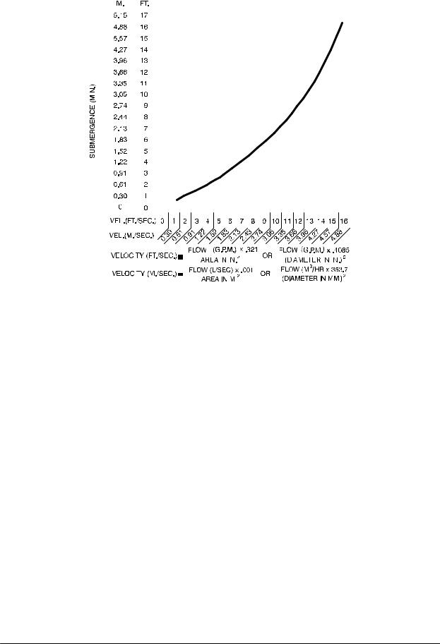
Suction Line Positioning
The depth of submergence of the suction line is critical to efficient pump operation. Figure 2 shows recommended minimum submergence vs. veloc ity.
NOTE
The pipe submergence required may be reduced by installing a standard pipe increaser fitting at the end of the suction line. The larger opening size will reduce the inlet velocity. Calculate the required submergence using the following formula based on the increased opening size (area or diameter).
PAGE B - 4 |
INSTALLATION |
SUPER T SERIES |
|
|
|
|
|
|
|
|
|
|
|
|
|
|
|
|
|
|
|
|
|
|
|
|
|
|
|
|
|
|
|
OM-05514 |
|||||||
|
|
|
|
|
|
|
|
|
|
|
|
|
|
|
|
|
|
|
|
|
|
|
|
|
|
|
|
|
|
|
|
|
|
|
|
|
|
|
|
|
|
|
|
|
|
|
|
|
|
|
|
|
|
|
|
|
|
|
|
|
|
|
|
|
|
|
|
|
|
|
|
|
|
|
|
|
|
|
|
|
|
|
|
|
|
|
|
|
|
|
|
|
|
|
|
|
|
|
|
|
|
|
|
|
|
|
|
|
|
|
|
|
|
|
|
|
|
|
|
|
|
|
|
|
|
|
|
|
|
|
|
|
|
|
|
|
|
|
|
|
|
|
|
|
|
|
|
|
|
|
|
|
|
|
|
|
|
|
|
|
|
|
|
|
|
|
|
|
|
|
|
|
|
|
|
|
|
|
|
|
|
|
|
|
|
|
|
|
|
|
|
|
|
|
|
|
|
|
|
|
|
|
|
|
|
|
|
|
|
|
|
|
|
|
|
|
|
|
|
|
|
|
|
|
|
|
|
|
|
|
|
|
|
|
|
|
|
|
|
|
|
|
|
|
|
|
|
|
|
|
|
|
|
|
|
|
|
|
|
|
|
|
|
|
|
|
|
|
|
|
|
|
|
|
|
|
|
|
|
|
|
|
|
|
|
|
|
|
|
|
|
|
|
|
|
|
|
|
|
|
|
|
|
|
|
|
|
|
|
|
|
|
|
|
|
|
|
|
|
|
|
|
|
|
|
|
|
|
|
|
|
|
|
|
|
|
|
|
|
|
|
|
|
|
|
|
|
|
|
|
|
|
|
|
|
|
|
|
|
|
|
|
|
|
|
|
|
|
|
|
|
|
|
|
|
|
|
|
|
|
|
|
|
|
|
|
|
|
|
|
|
|
|
|
|
|
|
|
|
|
|
|
|
|
|
|
|
|
|
|
|
|
|
|
|
|
|
|
|
|
|
|
|
|
|
|
|
|
|
|
|
|
|
|
|
|
|
|
|
|
|
|
|
|
|
|
|
|
|
|
|
|
|
|
|
|
|
|
|
|
|
|
|
|
|
|
|
|
|
|
|
|
|
|
|
|
|
|
|
|
|
|
|
|
|
|
|
|
|
|
|
|
|
|
|
|
|
|
|
|
|
|
|
|
|
|
|
|
|
|
|
|
|
|
|
|
|
|
|
|
|
|
|
|
|
|
|
|
|
|
|
|
|
|
|
|
|
|
|
|
|
|
|
|
|
|
|
|
|
|
|
|
|
|
|
|
|
|
|
|
|
|
|
|
|
|
|
|
|
|
|
|
|
|
|
|
|
|
|
|
|
|
|
|
|
|
|
|
|
|
|
|
|
|
|
|
|
|
|
|
|
|
|
|
|
|
|
|
|
|
|
|
|
|
|
|
|
|
|
|
|
|
|
|
|
|
|
|
|
|
|
|
|
|
|
|
|
|
|
|
|
|
|
|
|
|
|
|
|
|
|
|
|
|
|
|
|
|
|
|
|
|
|
|
|
|
|
|
|
|
|
|
|
|
|
|
|
|
|
|
|
|
|
|
|
|
|
|
|
|
|
|
|
|
|
|
|
|
|
|
|
|
|
|
|
|
|
|
|
|
|
|
|
|
|
|
|
|
|
|
|
|
|
|
|
|
|
|
|
|
|
|
|
|
|
|
|
|
|
|
|
|
|
|
|
|
|
|
|
|
|
|
|
|
|
|
|
|
|
|
|
|
|
|
|
|
|
|
|
|
|
|
|
|
|
|
|
|
|
|
|
|
|
|
|
|
|
|
|
|
|
|
|
|
|
|
|
|
|
|
|
|
|
|
|
|
|
|
|
|
|
|
|
|
|
|
|
|
|
|
|
|
|
|
|
|
|
|
|
|
|
|
|
|
|
|
|
|
|
|
|
|
|
|
|
|
|
|
|
|
|
|
|
|
|
|
|
|
|
|
|
|
|
|
|
|
|
|
|
|
|
|
|
|
|
|
|
|
|
|
|
|
|
|
|
|
|
|
|
|
|
|
|
|
|
|
|
|
|
|
|
|
|
|
|
|
|
|
|
|
|
|
|
|
|
|
|
|
|
|
|
|
|
|
|
|
|
|
|
|
|
|
|
|
|
|
|
|
|
|
|
|
|
|
|
|
|
|
|
|
|
|
|
|
|
|
|
|
|
|
|
|
|
|
|
|
|
|
|
|
|
|
|
|
|
|
|
|
|
|
|
|
|
|
|
|
|
|
|
|
|
|
|
|
|
|
|
|
|
|
|
|
|
|
|
|
|
|
|
|
|
|
|
|
|
|
|
|
|
|
|
|
|
|
|
|
|
|
|
|
|
|
|
|
|
|
|
|
|
|
|
|
|
|
|
|
|
|
|
|
|
|
|
|
|
|
|
|
|
|
|
|
|
|
|
|
|
|
|
|
|
|
|
|
|
|
|
|
|
|
|
|
|
|
|
|
|
|
|
|
|
|
|
|
|
|
|
|
|
|
|
|
|
|
|
|
|
|
|
|
|
|
|
|
|
|
|
|
|
|
|
|
|
|
|
|
|
|
|
|
|
|
|
|
|
|
|
|
|
|
|
|
|
|
|
|
|
|
|
|
|
|
|
|
|
|
|
|
|
|
|
|
|
|
|
|
|
|
|
|
|
|
|
|
|
|
|
|
|
|
|
|
|
|
|
|
|
|
|
|
|
|
|
|
|
|
|
|
|
|
|
|
|
|
|
|
|
|
|
|
|
|
|
|
|
|
|
|
|
|
|
|
|
|
|
|
|
|
|
|
|
|
|
|
|
|
|
|
|
|
|
|
|
|
|
|
|
|
|
|
|
|
|
|
|
|
|
|
|
|
|
|
|
|
|
|
|
|
|
|
|
|
|
|
|
|
|
|
|
|
|
|
|
|
|
|
|
|
|
|
|
|
|
|
|
|
|
|
|
|
|
|
|
|
|
|
|
|
|
|
|
|
|
|
|
|
|
|
|
|
|
|
|
|
|
|
|
|
|
|
|
|
|
|
|
|
|
|
|
|
|
|
|
|
|
|
|
|
|
|
|
|
|
|
|
|
|
|
|
|
|
|
|
|
|
|
|
|
|
|
|
|
|
|
|
|
|
|
|
|
|
|
|
|
|
|
|
|
|
|
|
|
|
|
|
|
|
|
|
|
|
|
|
|
|
|
|
|
|
|
|
|
|
|
|
|
|
|
|
|
|
|
|
|
|
|
|
|
|
|
|
|
|
|
|
|
|
|
|
|
|
|
|
|
|
|
|
|
|
|
|
|
|
|
|
|
|
|
|
|
|
|
|
|
|
|
|
|
|
|
|
|
|
|
|
|
|
|
|
|
|
|
|
|
|
|
|
|
|
|
|
|
|
|
|
|
|
|
|
|
|
|
|
|
|
|
|
|
|
|
|
|
|
|
|
|
|
|
|
|
|
|
|
|
|
|
|
|
|
|
|
|
|
|
|
|
|
|
|
|
|
|
|
|
|
|
|
|
|
|
|
|
|
|
|
|
|
|
|
|
|
|
|
|
|
|
|
|
|
|
|
|
|
|
|
|
|
|
|
|
|
|
|
|
|
|
|
|
|
|
|
|
|
|
|
|
|
|
|
|
|
|
|
|
|
|
|
|
|
|
|
|
|
|
|
|
|
|
|
|
|
|
|
|
|
|
|
|
|
|
|
|
|
|
|
|
|
|
|
|
|
|
|
|
|
|
|
|
|
|
|
|
|
|
|
|
|
|
|
|
|
|
|
|
|
|
|
|
|
|
|
|
|
|
|
|
|
|
|
|
|
|
|
|
|
|
|
|
|
|
|
|
|
|
|
|
|
|
|
|
|
|
|
|
|
|
|
|
|
|
|
|
|
|
|
|
|
|
|
|
|
|
|
|
|
|
|
|
|
|
|
|
|
|
|
|
|
|
|
|
|
|
|
|
|
|
|
|
|
|
|
|
|
|
|
|
|
|
|
|
|
|
|
|
|
|
|
|
|
|
|
|
|
|
|
|
|
|
|
|
|
|
|
|
|
|
|
|
|
|
|
|
|
|
|
|
|
|
|
Figure 2. Recommended Minimum Suction Line Submergence vs. Velocity
FLOAT SWITCHES
Installation
The standard pump is equipped with an auto start control system, and can be conformed to start and stop as the liquid level in the wet well or sump rises and falls. The autostart unit employs either a single or double float switch system, where a bulb raises or lowers (floats) with the liquid level, thus activat ing an enclosed miniature switch. The floats are equipped with a socket type connector that plugs into a matching receptacle on the auto start control box.
Standard floats are equipped with 50 feet (15,2 m) of cable.
When installing the floats, note the following:
a.Be sure to provide sufficient room in the wet well or sump so that floats do not get ob structed or drawn into the suction line. If a flex ible suction hose is used, it may be extended to lay along the bottom of the wet well or sump and the float can be attached to the hose
above the point where it bends along the bot tom. Direct the suction line toward the flow, and the float(s) away from the flow. If a stand pipe is available, attach the float switch cable to the standpipe in the sump at the approxi mate desired liquid level.
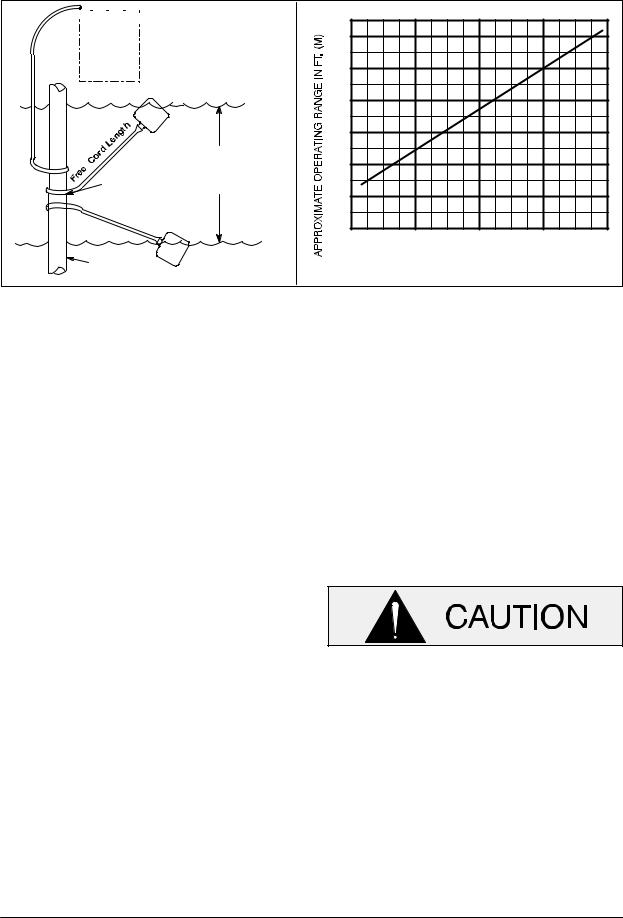
b.In a single float system, the cable can be teth ered to the suction line or standpipe approxi mately 6 inches (152 mm) above the float.
This setting allows approximately 9 inches (229 mm) of liquid rise between pump start/ stop. The start/stop interval may be increased by extending the float end of the cable. The liquid level in the sump will increase approxi mately 8 inches (203 mm) between start/stop intervals for every 6 inches (152 mm) of cable increase.
c.If a double float switch system is used, posi tion the “Start” float at the desired high water level in the sump, and the “Stop” float at the desired low water level in the pump.
d.Refer to Figure 3 for additional float switch data.
INSTALLATION |
PAGE B - 5 |
OM-05514 |
|
|
|
|
|
|
|
|
|
SUPER T SERIES |
|
|
|
|
|
|
|
|
|
|
|
|
|
|
|
|
|
|
|
|
|
|
|
|
|
|
|
|
|
|
|
|
|
ENGINE |
|
3.0 |
|
|
|
|
(0.9) |
|
|
|
|
CONTROL |
|
|
|
|
|
|
|
|
|
|
|
BOX |
|
2.5 |
|
|
|
|
ON |
(.76) |
|
|
|
|
|
|
|
|
|
|
(Emptying) |
2.0 |
|
|
|
|
|
(0.6) |
|
|
|
|
OFF |
1.5 |
|
|
|
|
(Filling) |
|
|
|
|
|
|
(.46) |
|
|
|
|
OPERATING |
1.0 |
|
|
|
CABLE |
RANGE |
(0.3) |
|
|
|
(See Table Below) |
|
|
|
|
|
TETHER |
0.5 |
|
|
|
|
POINT |
|
(.15) |
|
|
|
|
OFF |
|
|
|
|
|
(Emptying) |
1.0 |
2.0 |
3.0 |
4.0 |
|
|
||||
|
ON |
(0.3) |
(0.6) |
(0.9) |
(1.2) |
|
APPROXIMATE FREE CORD LENGTH IN FT. (M) |
|
|||
1.25” Pipe |
(Filling) |
|
|||
(Not Furnished) |
|
|
|
|
|
Figure 3. Float Switch Data
OPTIONAL SUBMERSIBLE
TRANSDUCER
This unit may be equipped with an optional Elec tronic Pressure Switch (EPS) that works in con junction with a submersible transducer. The sub mersible transducer converts pressure to an elec trical signal proportional to liquid level. This electri cal signal is distributed to the digital display on the
EPS through a scaling circuit which converts the electrical signal to “feet of water”.
When installing the submersible transducer, note the following:
a.Handle the signal cable and transducer with care during installation. Carefully lower the transducer into the wet well or sump; do not drop it to the bottom. To avoid clogging, sus pend the transducer off the bottom.
b.Be sure to provide sufficient room in the wet well or sump so that the transducer does not get drawn into the suction line. To prevent this, a flexible suction hose may be extended to lay along the bottom of the wet well or sump. The transducer can then be attached to the hose
above the point where it bends along the bot tom. See Figure B-4 for a typical installation.
c.The wet well or sump must be vented to atmo sphere.
d.The EPS is scaled in feet of water column. If the measured medium is other than 1.0 spe cific gravity, the reading on the EPS should be divided by the specific gravity of the mea sured medium to obtain the actual level.
e.Thoroughly clean the transducer after each use to prevent clogging.
Do not disassemble the transducer or loosen the compression nut at the signal cable entry. This will void warranty. There are no user serviceable parts inside. Do not nick or cut the jacket of the signal cable; this will cause leakage and void warranty.
PAGE B - 6 |
INSTALLATION |

SUPER T SERIES |
OM-05514 |
|
|
SUCTION
DISCHARGE LINE
LINE
SIGNAL CABLE (ATTACH TO SUCTION LINE)
SUBMERSIBLE |
SUCTION |
|
STRAINER |
||
TRANSDUCER |
||
|
||
(DOWNSTREAM |
|
|
FROM SUCTION) |
FLOW |
|
|
Figure 4. Typical Submersible Transducer Installation
DISCHARGE LINES
Siphoning
Do not terminate the discharge line at a level lower than that of the liquid being pumped unless a si phon breaker is used in the line. Otherwise, a si phoning action causing damage to the pump could result.
Valves
If a throttling valve is desired in the discharge line, use a valve as large as the largest pipe to minimize friction losses. Never install a throttling valve in a suction line.
With high discharge heads, it is recommended that a throttling valve and a system check valve be in stalled in the discharge line to protect the pump from excessive shock pressure and reverse rota tion when it is stopped.
If the application involves a high discharge head, gradually close the discharge throttling valve before stopping the pump.
Bypass Lines
Self priming pumps are not air compressors. Dur ing the priming cycle, air from the suction line must be vented to atmosphere on the discharge side. If the discharge line is open, this air will be vented through the discharge. However, if a check valve has been installed in the discharge line, the dis charge side of the pump must be opened to atmos pheric pressure through a bypass line installed be tween the pump discharge and the check valve. A self priming centrifugal pump will not prime if there is sufficient static liquid head to hold the dis charge check valve closed.
NOTE
The bypass line should be sized so that it does not
INSTALLATION |
PAGE B - 7 |
OM-05514 |
SUPER T SERIES |
|
|
affect pump discharge capacity; however, the by pass line should be at least 1 inch (25,4 mm) in di ameter to minimize the chance of plugging.
In low discharge head applications (less than 30 feet (9,1 m)), it is recommended that the bypass line be run back to the wet well, and located 6 inches below the water level or cut off point of the low level pump. In some installations, this bypass outline may be terminated with a six to eight foot
(1,8 to 2,4 m) length of 1 1/4 inch (31,8 mm) I.D. smooth bore hose; air and liquid vented during the priming process will then agitate the hose and break up any solids, grease, or other substances likely to cause clogging.
A bypass line that is returned to a wet well must be secured against being drawn into the pump suction inlet.
It is also recommended that pipe unions be in stalled at each 90_ elbow in a bypass line to ease disassembly and maintenance.
In high discharge head applications (more than
30 feet (9,1 m), an excessive amount of liquid may be bypassed and forced back to the wet well under the full working pressure of the pump; this will re duce overall pumping efficiency. Therefore, it is recommended that a Gorman Rupp Automatic Air Release Valve be installed in the bypass line.
Gorman Rupp Automatic Air Release Valves are reliable, and require minimum maintenance. See
Automatic Air Release Valves in this section for installation and theory of operation of the Auto matic Air Release Valve. Consult your Gorman
Rupp distributor, or contact the Gorman Rupp Company for selection of an Automatic Air Release Valve to fit your application.
lift station), if a manual shut off valve is in stalled anywhere in a bypass line, it must be a full opening, ball type valve to pre vent plugging by solids.
A manual shut off valve should not be installed in any bypass line. A manual shut off valve may inadvertently be left closed during operation. A pump which has lost prime may continue to operate without reaching prime, causing dan gerous overheating and possible explo sive rupture of the pump casing. Per sonnel could be severely injured.
Allow an over heated pump to com pletely cool before servicing. Do not re move plates, covers, gauges, or fittings from an over heated pump. Liquid with in the pump can reach boiling tempera tures, and vapor pressure within the pump can cause parts being disen gaged to be ejected with great force. Af ter the pump completely cools, drain the liquid from the pump by removing the casing drain plug. Use caution when re moving the plug to prevent injury to per sonnel from hot liquid.
AUTOMATIC AIR RELEASE VALVE
When properly installed, a Gorman Rupp Auto matic Air Release Valve will permit air to escape through the bypass line and then close automati cally when the pump is fully primed and pumping at full capacity.
Except in certain specific applications (to prevent flooding during service of an auto matic air release valve in a below ground
Some leakage (1 to 5 gallons [3.8 to 19 liters] per minute) will occur when the valve is fully closed. Be sure the bypass line is directed back to the wet well or tank to prevent hazardous spills.
PAGE B - 8 |
INSTALLATION |
 Loading...