

GORMAN-RUPP PUMPS T SERIES, T10A61-B Installation, Operation And Maintenance Manual
CDSW
OM---01936---OB03
August 15, 1984
Rev. K 11/22/02
INSTALLATION, OPERATION,
AND MAINTENANCE MANUAL
WITH PARTS LIST
TSERIESPUMP
MODEL
T10A61---B
INCLUDING: /FM, /WW
THE GORMAN-RUPP COMPANY D MANSFIELD, OHIO
GORMAN-RUPP OF CANADA LIMITED D ST. THOMAS, ONTARIO, CANADA Printed in U.S.A.
www.gormanrupp.com
ECopyright by the Gorman-Rupp Company

TABLE OF CONTENTS
INTRODUCTION PAGE I --- 1.................................................
SA FE TY --- SECTION A PA GE A --- 1...........................................
IN STALLAT ION --- SECTION B PA GE B --- 1....................................
Pump Dimensions PAGE B --- 1.....................................................
PREINSTALLATION INSPECTION PAGE B --- 1............................................
Battery Specifications And Installation PAGE B --- 2....................................
POSITIONING PUMP PA GE B --- 2.......................................................
Lifting PA GE B --- 2.................................................................
Mounting PA GE B --- 2.............................................................
SUCTION AND DISCHARGE PIPING PAGE B --- 2.........................................
Materials PA GE B --- 2..............................................................
Line Configuration PAGE B --- 2......................................................
Connections to Pump PAGE B --- 2..................................................
Gauges PA GE B --- 3...............................................................
SUCTION LINES PAGE B --- 3...........................................................
Fittings PA GE B --- 3...............................................................
Strainers PA GE B --- 3..............................................................
Sealing PAGE B --- 3...............................................................
Suction Lines In Sumps PAGE B --- 3.................................................
Suction Line Positioning PAGE B --- 3................................................
DISCHARGE LINE S PA GE B --- 4........................................................
Siphoning PA GE B --- 4.............................................................
Valves PA GE B --- 4................................................................
Bypass Lines PA GE B --- 4..........................................................
AUTOMATIC AIR RELEASE VALVE PAGE B --- 5...........................................
Theory of Operation PAGE B --- 6....................................................
Air Release V alve Installation P AGE B --- 6............................................
ALIGNMENT PAGE B --- 7..............................................................
Coupled Drives PA GE B --- 8........................................................
V-Belt Drives PA GE B --- 8...........................................................
OP E R ATION --- SE CTION C PAGE C --- 1......................................
PRIMING PA GE C --- 1.................................................................
STARTING PA GE C --- 1................................................................
OPERATION PA GE C --- 1..............................................................
Lines With a Bypass PAGE C --- 1....................................................
Lines Without a Bypass PAGE C --- 1.................................................
Leakage PAGE C --- 2..............................................................
Liquid Temperature And Overheating PAGE C --- 2.....................................
Strainer Check PAGE C --- 2.........................................................
Pump Vacuum Check PAGE C --- 2..................................................
STOPPING PA GE C --- 3................................................................
Cold Weather Preservation PAGE C --- 3..............................................
BEARING TEMPERATURE CHECK PAGE C --- 3..........................................
TROUBLESHOO T I N G --- S E C T I O N D PA G E D --- 1..............................
PREVENTIVE MAINTENANCE PAGE D --- 3...............................................
i

TABLE OF CONTENTS
(continued)
PUMP MAINTENANCE AND REPAIR --- SECTION E PAGE E --- 1................
PERFORMANCE CURVE PA GE E --- 1...................................................
PARTS LISTS:
Pump Model PAGE E --- 3..........................................................
Repair Rotating Assembly PAGE E --- 5...............................................
PUMP AND SEAL DISASSEMBLY AND REASSEMBLY PAGE E --- 6.........................
Cleanout Access And Suction Check Valve Removal PAGE E --- 6.......................
Suction Head And Wear Plate Removal PAGE E --- 6...................................
Rotating Assembly Removal PAGE E --- 7.............................................
Impeller Removal P AGE E --- 8......................................................
Seal Removal And Disassembly PAGE E --- 8.........................................
Shaft and Bearing Removal and Disassembly PAGE E --- 8.............................
Shaft and Bearing Reassembly and Installation P AGE E - -- 9............................
Seal Reassembly and Installation P AGE E --- 10........................................
Impeller Installation PAGE E --- 12.....................................................
Rotating Assembly Installation PAGE E --- 13...........................................
Suction Head And Wear Plate Installation PAGE E --- 13.................................
Suction Check Valve Installation P AGE E - -- 13.........................................
PRESSURE RELIEF VALVE MAINTENANCE PAGE E --- 14..................................
LUBRICATION PA GE E --- 14.............................................................
Seal Assembly PAGE E --- 14.........................................................
Bearings PAGE E --- 14..............................................................
ii
TSERIES
OM--01936
INTRODUCTION
Thank You for purchasing a Gorman-Rupppump.
Read this manual carefully to learn how to safely
install and operate your pump. Failure to do so
could result in personal injury or damage to the
pump.
This Installation, Operation, and Maintenance
manual is designed to help you achieve the best
performance and longest life from your GormanRupp pump.
This pump is a T Series, semi-open impeller, selfpriming centrifugal model with a suction check
valve. The pump is designed for handling mild industrial corrosives, residues and slurries containing large entrained solids. The basic material of
construction is gray iron, with stainless steel impeller , impeller shaft and wearing parts.
Ifthereare anyquestionsregarding thepump orits
applicationwhichare not coveredin thismanualor
in other literature accompanying this unit, please
contact your Gorman -Rupp distributor, or write:
promised by the installation. Pumps and related
equipment must be installed and operated ac-
cording to all national, local and industry standards.
The following are used to alert maintenance personnel to procedures which require special attention, tothosewhich coulddamage equipment,and
to those which could be dangerous to personnel:
Immediate hazardswhich WILL result in
severe personal injury or death. These
instructions describe the procedure required and the injury which will result
from failure to follow the procedure.
The Gorman-Rupp Company
P.O. Box 1217
Mansfield, Ohio 44901-- 1217
Phone: (419) 755--1011
or:
Gorman-Rupp of Canada Limited
70 Burwell Road
St. Thomas, Ontario N5P 3R7
Phone: (519) 631--2870
Forinformationor technicalassistance onthepower source, contact the power source manufacturer’s local dealer or representative.
Because pump installations are seldom identical,
this manual cannot possibly provide detailed instructions and precautions for every aspect of
each specific application. Therefore, it is the responsibility of the owner/installer of the pump to
ensure that applications not addressed in this
manual are performed only after establishing that
neither operatorsafetynorpumpintegrity are com-
Hazards or unsafe practices which
COULDresult in severe personal injury
or death. These instructions describe
the procedure required and the injury
which could result from failure to follow
the procedure.
HazardsorunsafepracticeswhichCOULD
result in minor personal injury or product
or property damage. These instructions
describe the requirements and the possibledamagewhich couldresult fromfailure
to follow the procedure.
NOTE
Instructions to aid in installation, operation,and
maintenance, or which clarify a procedure.
PAGE I -- 1INTRODUCTION
TSERIES OM--01936
SAFETY --- SECTION A
This information applies to T Series basic pumps. Gorman-Rupp has no control over or particular knowledge of the
powersourcewhichwill be used. Refer
to the manual accompanying the power
source before attempting to begin operation.
Because pump installations are seldom
identical, this manual c annot possibly
provide detailed instructions and precautions for each specific application.
Therefore, it is the owner/installer’s responsibility to ensure that applications
not addressed in this manual are performed only
after establishing that neither operator safety nor pump integrity
are compromised by the installation.
This pump is designed to handle mild
industrial corrosives, mud and slurries
containing large entrained solids. Do
not attempt to pump volatile, flammable, or highly corrosive liquids
which may damage thepump or endanger personnel as a result of pump failure.
After the pump has been positioned,
make certain that the pump and all piping connections are tight, properlysupported and secure before operation.
Beforeattemptingto open orservice the
pump:
1. Familiarize yourself with this manual.
2. Disconnect or lock out the power
source, or take other action to ensure that the pump will remain inoperative.
3. Allow the pump to completely cool
if overheated.
4. Vent the pump slowly and cautiously.
5. Close the suction and discharge
valves.
6. Check the temperature before
opening any covers, plates, or
plugs.
7. Drain the pump.
Do not operate the pump without
shields and /or guards in place over the
drive shafts, belts and/or couplings, or
other rotating parts. Exposed rotating
parts can catch clothing, fingers, or
tools. causing severe injury to personnel.
Do not operate the pump against a
closed discharge valve for long periods
oftime.Ifoperatedagainstacloseddischarge valve, pump components will
deteriorate, and the liquid could come
to a boil, build pressure, and cause the
pump casing to rupture or e xplode.
PAGE A -- 1SAFETY
TSERIESOM--01936
Use lifting and moving equipment in
good repair and with adequate capacity
toprevent injuries to personnelor damage to equipment.
Overheated pumps can cause severe
burns and injury. If overheating of the
pump occurs:
1. Stop the pump immediately.
2. Allowthepumpto completelycool.
3. Refer to instructions in thismanual
before restarting the pump.
Donotattempttodisengageanypartof
an overheated pump unit. Vapor pres sure within the pump casing can eject
these parts with great force when they
are disengaged. Allow the pump to
completely cool before servicing it.
Use lifting and moving equipment in
good repair and with adequate capacity
toprevent injuries to personnelor damage to equipment.
PAGE A -- 2 SAFETY
INSTALLATION --- SECTION B
OM--01936TSERIES
Review all SAFETY information in Section A.
Since pump installationsareseldomidentical,this
section offers only general recommendations and
practices required to inspect, position, and arrange the pump and piping.
Most of the information pertains to a standard
static lift application where the pump is posi-
tionedabovethefreelevelofliquidto bepumped.
If installed ina floodedsuction application where
the liquid is supplied to the pump under pressure,
some of the information such as mounting, line
OUTLINE DRAWING
configuration, and priming must be tailored to the
specific application. Since the pressure supplied
to the pump is critical to performance and safety,
be sure to limit the incoming pressure to 50% of
the maximum permissible operating pressure as
shown on the pump performance curve.
Forfurtherassistance, contact yourGorman-Rupp
distributor or the Gorman-Rupp Company.
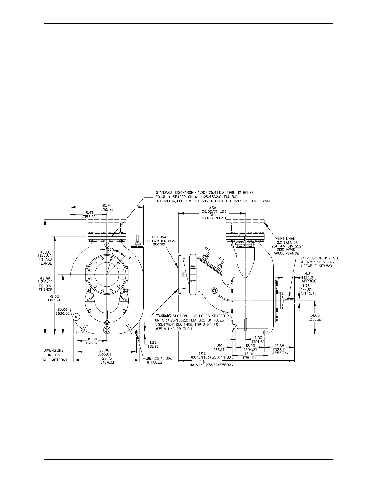
Pump Dimensions
SeeFigure1fortheapproximatephysicaldimensionsofthispump.
Figure 1. Pump Model T10A61--B
PREINSTALLATION INSPECTION
Thepump assemblywasinspected and tested beforeshipment from the factory. Before installation,
inspect the pump fordamage which may have occurred during shipment. Check as follows:
a. Inspectthe pump forcracks, dents,damaged
threads, and other obvious damage.
b. Check for and t ighten loose attaching hard-
ware. Since gaskets tend to shrink after drying, check for loose hardware at mating s urfaces.
c. Carefully read all warnings and cautions con-
tained in this manual or affixed to the pump,
and perform all duties indicated. Note the direction of rotation indicated on the pump.
PAGE B -- 1INSTALLATION
OM--01936 TSERIES
Check that the pump shaft rotates counterclockwise when facing the impeller.
Thepumpassemblycanbeseriously
damagedifthecablesor chainsused tolift
andmovetheunitareimproperlywrapped
Only operate this pump in the direction indicated by the arrow on the pump body
and on the accompanying decal. Refer to
Rotation in OPERATION,SectionC.
d. Checklevels and lubricate as necessary. Re-
fer to LUBRICATION in the MAINTENANCE
AND REPAIRsection of this manual and perform duties as instructed.
e.Ifthepumpandpowersourcehavebeen
stored for more than 12 months, some of the
components or lubricants may have exceeded their maximum shelf life. These must
be inspected or replaced to ensure maximum pump service.
If the maximum shelf life has been exceeded, or if
anything appears to be abnormal, contact your
Gorman-Rupp distributor or the factory to determinethe repair or updating policy. Do notputthe
pump into service until appropriate action has
been taken.
POSITIONING PUMP
Lifting
around the pump.
Mounting
Locatethepump inanaccessibleplaceas closeas
practicalto the liquid being pumped. Levelmounting is essential for proper operation.
The pump may have to be supported or shimmed
to provide for level operation or to eliminate vibration.
SUCTION AND DISCHARGE PIPING
Pump performance is adversely effected by increased suction lift, discharge elevation, and friction losses. See the performance curve and operating range shown on Page E-1 to be sure your
overall application allows the pump to operate
within the safe operation range.
Materials
Either pipe or hose maybe used for suction and
discharge lines; however, the materials must be
compatiblewiththe liquidbeingpumped. If hoseis
used in suctionlines, it mustbe the rigid-wall, reinforcedtype toprevent collapse under suction.Using piping couplings in suction lines is not recommended.
Use lifting equipment with a capacity of at least
6,700 pounds. This pump weighs approximately
1,340 pounds, not including the weight of acces-
soriesor customerinstalledequipment. Customer
installed equipment such as suction and dischargepipingmust beremoved beforeattempting
to lift.
Make sure that hoists and other lifting equipment
areof sufficientcapacitytos afely handle thepump
assembly.Ifchains andcablesare used,make certain that they are positioned so that they will not
damage thepump, andso that the load willbe balanced.
PAGE B -- 2 INSTALLATION
Line Configuration
Keep suction and discharge lines as straight as
possible to minimize friction losses. Make minimum use of elbows and fittings, which substantiallyincreasefriction loss.Ifelbowsarenecessary,
use the long-radius type to minimize friction loss.
Connections to Pump
Before tightening a connecting flange, align it exactlywith t he pump port. Never pulla pipeline into
place by tightening the flange bolts and/or cou plings.

OM--01936TSERIES
Lines near the pump must be independently supported to avoid strain on the pump which could
cause excessive vibration, decreased bearing life,
and increased shaft and seal wear. If hose-type
linesare used, theyshouldhave adequatesupport
to secure them when filled with liquid and under
pressure.
Gauges
Most pumps are drilled and tapped for installing
dischargepressureandvacuumsuctiongauges.If
these gauges are desired for pumps that are not
tapped, drill and tap the suction and discharge
lines not less than 18 inches (457 mm) from the
suction and discharge ports and install the lines.
Installationcloserto the pump may result inerratic
readings.
SUCTION LINES
Toavoidair pockets whichcouldaffect pumppriming, the suction line must be as short and direct as
possible.Whenoperationinvolvesasuctionlift,the
line must always slope upward to the pump from
the source of the liquid being pumped; if the line
slopes down to the pump at any point along the
suction run, air pockets will be created.
Fittings
three or four times the cross section of the suction
line,and that the openings willnot permit passage
of solids larger than the solids handling capability
of the pump.
Thispump is designedto handleup to 3-inch (76,2
mm) diameter spherical solids.
Sealing
Since even a slight leak will affect priming, head,
and capacity, especially when operating with a
high suction lift, all connections in the suction line
should be sealed with pipe dope to ensure an airtight seal. Follow the sealant manufacturer’s recommendations when selecting and applying the
pipe dope. The pipe dope should be compatible
with the liquid being pumped.
Suction Lines In Sumps
If a single suction line is installed in a sump, it
should be positioned away from the wall of the
sumpat a distanceequalto 1-1/2timesthediameter of the suction line.
If there is a liquid flow from an open pipe into the
sump, the flow should be kept away from the suctioninlet because the inflow willcarry air down into
the sump, and air entering the suction line will reduce pump efficiency .
Suction lines shouldbethe same sizeas the pump
inlet. If reducers are used in suction lines, they
should be the eccentric type, and should be installedwith the flat part of the reducers uppermost
to avoid creating air pockets. Valves are not normally used in suction lines, but if a valve is used,
install it w ith the stem horizontal to avoid air pockets.
Strainers
If a s trainer is furnished with the pump, be certain
touse it;any sphericalsolidswhichpass througha
strainer furnished with the pump will also pass
through the pump itself.
If a strainer is not furnished with the pump, but is
installed by the pump user, make certain that the
total area of the openings in the strainer is at least
Ifitis necessary to positioninflowcloseto the suctioninlet, installa bafflebetween theinflow and the
suctioninlet at a distance 1-1/2 times the diameter
of the suction pipe. The baffle will allow entrained
air to escape from the liquid before it is drawn into
the suction inlet.
If two suction lines are installed in a single sump,
theflow pathsmayinteract, reducingtheefficiency
of one or both pumps. To avoid this, position the
suction inlets so that they are separated by a distance equal to at least 3 times the diameter of the
suction pipe.
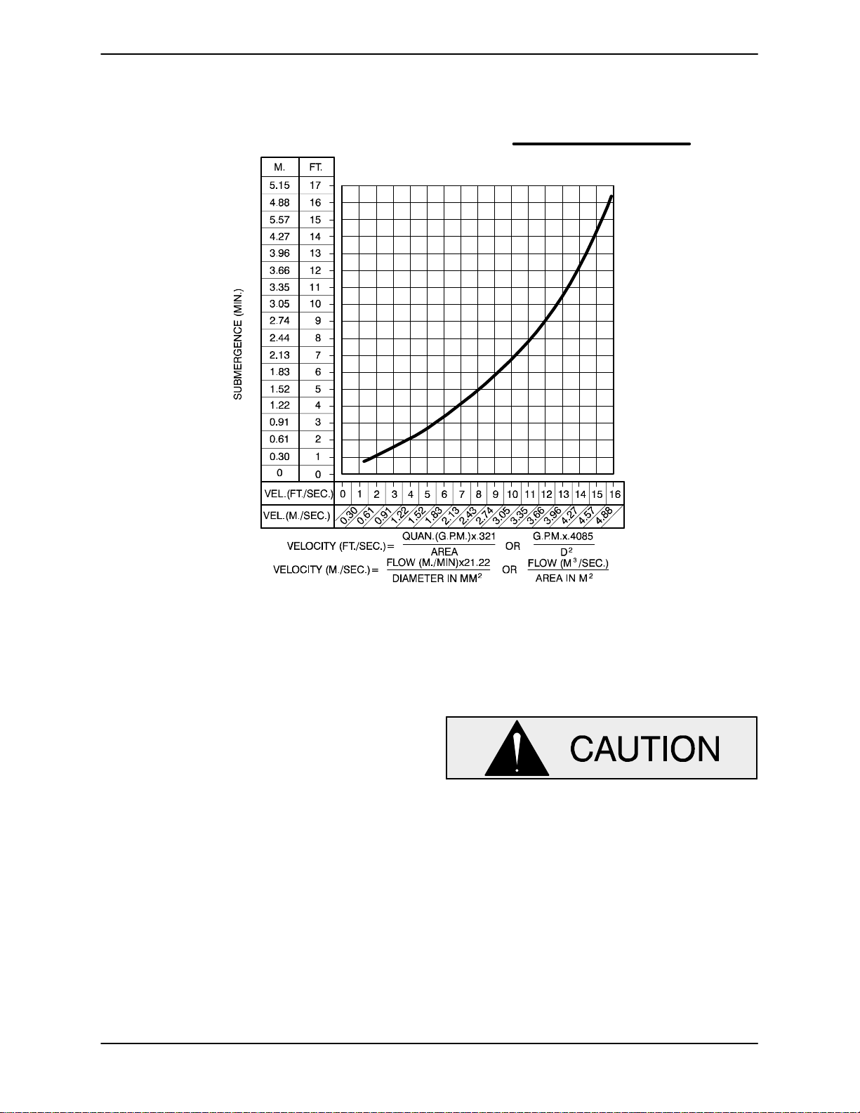
Suction Line Positioning
The depth of submergence of the suction line is
critical to efficient pump operation. Figure 2 shows
recommended minimum submergence vs. veloc-
ity.
PAGE B -- 3INSTALLATION
OM--01936 TSERIES
NOTE
The pipe submergence required may be reduced
byinstalling a standard pipe increaser fittingatthe
endof the suctionline.The larger opening size will
reduce the inlet velocity . Calculate the required
submergence using the following formula based
on the increased opening size (area or diameter).
Figure 2. Recommended Minimum Suction Line Submergence vs. Velocity
DISCHARGE LINES
Siphoning
Donot terminate the dischargeline at a levellower
than that of the liquid being pumped unless a siphon breaker is used in the line. Otherwise, a siphoning action causing damage to the pump
could result.
Valves
A check valve in the discharge lineis normallyrecommended, but it is not necessary in low discharge head applications.
If a throttling valve is desired in the discharge line,
useavalveaslargeasthelargestpipetominimize
friction losses. Never install a throttling valve in a
suction line.
Withhighdischarge heads,it isrecommendedthat
a throttling valve and a system check valve be installed in the discharge line to protect the pump
from excessive shock pressure and reverse rotation when it is stopped.
Iftheapplicationinvolvesa highdischarge
head, gradually close the discharge
throttling valve before stopping the pump.
Bypass Lines
If it is mecessary to permit the escape of air to atmosphere during initial priming or in the repriming
cycle, install a bypass line between th epump and
thedischarge check valve. Thebypasslineshould
be sized so that it does not affect pump discharge
capacity.
ItisrecommendedthataGorman---RuppAutomatic Air Release Valve be installed in the bypass line.
PAGE B -- 4 INSTALLATION
OM--01936TSERIES
Do Not install a manual shut---off valvein a bypass
line. If a manual shut---offvalve is installedto facilitateservice ofthe AirReleaseValve,the valvemust
not be left closed during operation. See the supplement at the end of this section for additionalinformationon bypass linesand the Gorman---Rupp
Automatic Air Release Valve.
NOTE
Thebypass line may clog occasionally, particularly
when pumping liquids containing large solids. If
clogging occurs, locate and remove theclog. Ifthe
clog is located between the discharge check valve
andtheAir ReleaseValve, thevalvewillnotclose. If
theclog is locatedin theReliefValveitself, or in the
line between the Relief Valve and the sump, the
valve will not open.
Donot terminate the dischargeline at a levellower
than that of the liquid being pumped unless a siphon breaker is used in the line; otherwise, a siphoning action could result, causing damage to
the pump.
Inlow discharge headapplications(less than30
feet or 9,1 meters), it is recommended that the bypass line be run back to thewet well, and located 6
inches (152,4 mm) below the water level or cut-off
point of the low level pump. In some installations,
this bypass line may be terminated with a six-toeight foot length of 1-1/4 inch (31,8 mm) I.D.
smooth-bore hose; air and liquid vented during
the priming process will then agitate the hose and
break up any solids, grease, or other substances
likely to cause clogging.
A bypass line that is returned to a wetwell
must be secured againstbeing d rawn into
the pump suction inlet.
this will reduce overall pumping efficiency. There-
fore, it is recommended that a Gorman-Rupp
Automatic Air Release Valve be installed in the
bypass line.
Gorman-Rupp Automatic Air Release Valves are
reliable, and require minimum maintenance. See
AUTOMATICAIR RELEASE VALVEin this section
for installation and theory of operation of the Automatic Air Release Valve. Consult your GormanRupp distributor, or contact the Gorman-Rupp
CompanyforselectionofanAutomaticAirRelease
Valve to fit your application.
A manual shut-off valve should not be
installed in any bypass line. A manual
shut-off valve may inadvertently be left
closed during operation. A pump which
has lost prime may continue to operate
without reaching prime, causing dangerousoverheatingand possible explosive rupture of the pump casing. Personnel could be severely injured.
Allow an over-heated pump to cool before servicing. Do not remove plates,
covers,gauges,orfittings fromanoverheated pump. Liquid within the pump
canreachboilingtemperatures,andvaporpressure within the pumpcan cause
parts being disengaged to be ejected
with great force. After the pump cools
drain the liquid from the p ump by removing the casing drain plug. Use caution when removing the plug to prevent
injury to personnel from hot liquid.
,
It is also recommended that pipe unions be installed at each 90_ elbow in a bypass line to ease
disassembly and maintenance.
In high discharge head applications (more than
30 feet or 9,1 meters), an excessive amount of liquid may be bypassed and forced back to the wet
well under the full working pressure of the pump;
AUTOMATIC AIR RELEASE VALVE
When properly installed and correctly adjusted to
the specific hydraulic operating conditions of the
application, the Gorman-Rupp Automatic Air ReleaseValvewillpermitairtoescapethroughthebypass line, and then close automatically when the
pump is fully primed and pumping at full capacity.
PAGE B -- 5INSTALLATION
OM--01936 TSERIES
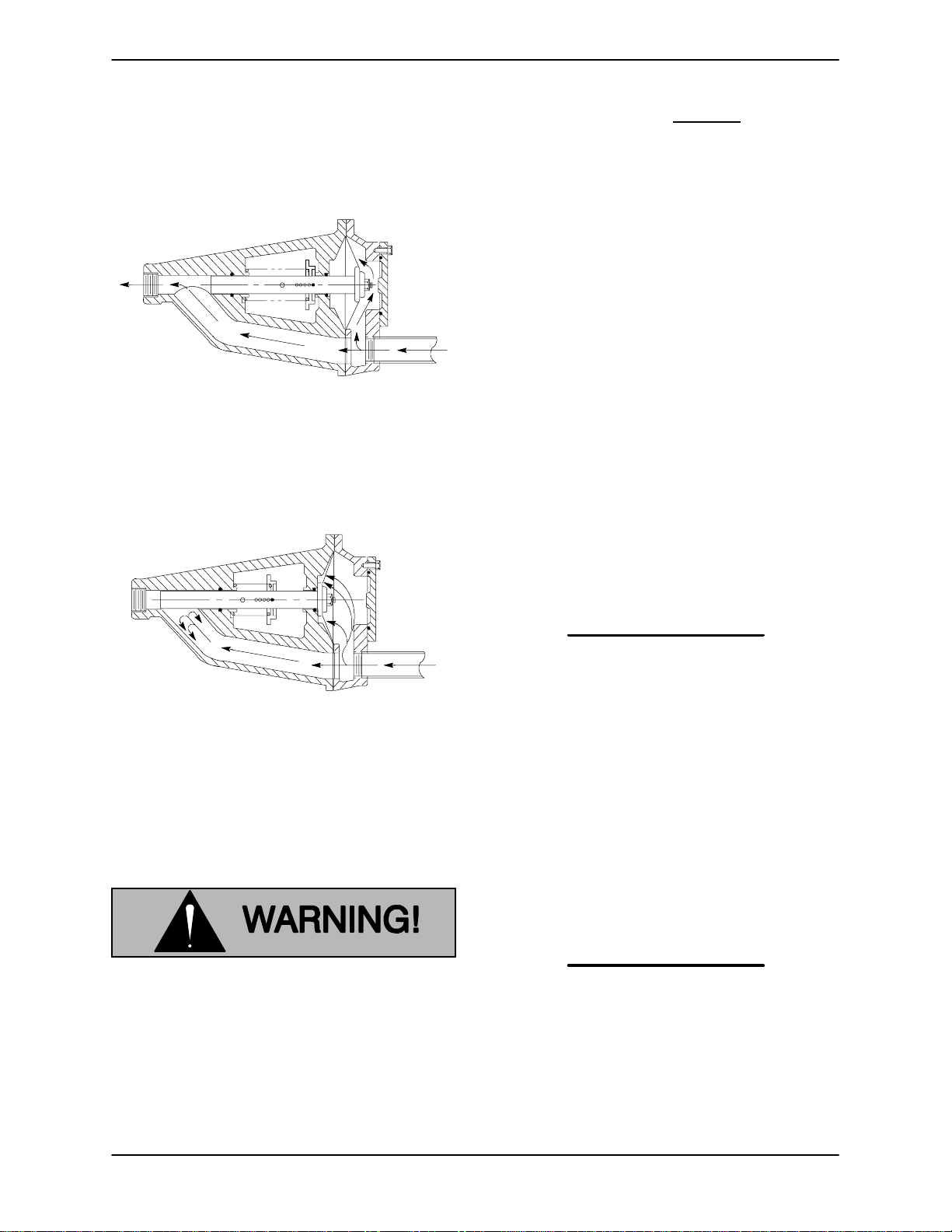
Theory of Operation
Figures 3 and 4 show a cross-sectional view of the
AutomaticAir Release Valve, and a corresponding
description of operation.
Figure 3 Valve in Open Position
Duringthe primingcycle, airfromthe pump casing
flowsthroughthebypassline,andpassesthrough
theAirReleaseValvetothewetwell(Figure3).
liters] per minute) will occur when the
valve is fully closed.Be sure
the bypass
line is directed back to the wet well or
tank to prevent hazardous spills.
Whenthe pump shutsdown, thespring returnsthe
diaphragm to its original position. Any solids that
mayhave accumulatedin the diaphragm chamber
settle to the bottom and are flushedout during the
next priming cycle.
NOTE
The valve will remain open if the pump does not
reach its designed capacity or head. V alveclosing
pressureis dependentupon thedischargeheadof
the pump at full capacity. The range of the valve
closing pressure is established by the tensionrate
ofthespringasorderedfrom thefactory.Valveclosing pressure can be further adjusted to the exact
system requirements by moving the spring retaining pin up or down the plunger rod to increase or
decrease tension on the spring. Contact your Gorman-Rupp distributor or the Gorman-Rupp Company for information about an Automatic Air Release Valve for your specific application.
Figure 4 Valve in Closed Position
When the pump is fully primed, pressure resulting
from flow against the valve diaphragm compresses the spring and closesthe valve(Figure 4).
The valve will remain closed, reducing the bypass
ofliquidto 1to5 gallonsper minute,untilthepump
loses its prime or stops.
Some le akage (1 to 5 gallons [3.8 to 19
Air Release Valve Installation
The A utomatic Air Release Valve must be inde pendently mounted in a horizontal position and
connected to the discharge line of the self-priming
centrifugal pump (see Figure 5).
NOTE
IftheAirReleaseValveistobeinstalledonastaged
pump application, contact the factory for specific
installationinstructions.
PAGE B -- 6 INSTALLATION
 Loading...