

Page 1
CDSW
OM---01936---OB03
August 15, 1984
Rev. K 11/22/02
INSTALLATION, OPERATION,
AND MAINTENANCE MANUAL
WITH PARTS LIST
TSERIESPUMP
MODEL
T10A61---B
INCLUDING: /FM, /WW
THE GORMAN-RUPP COMPANY D MANSFIELD, OHIO
GORMAN-RUPP OF CANADA LIMITED D ST. THOMAS, ONTARIO, CANADA Printed in U.S.A.
www.gormanrupp.com
ECopyright by the Gorman-Rupp Company
Page 2

TABLE OF CONTENTS
INTRODUCTION PAGE I --- 1.................................................
SA FE TY --- SECTION A PA GE A --- 1...........................................
IN STALLAT ION --- SECTION B PA GE B --- 1....................................
Pump Dimensions PAGE B --- 1.....................................................
PREINSTALLATION INSPECTION PAGE B --- 1............................................
Battery Specifications And Installation PAGE B --- 2....................................
POSITIONING PUMP PA GE B --- 2.......................................................
Lifting PA GE B --- 2.................................................................
Mounting PA GE B --- 2.............................................................
SUCTION AND DISCHARGE PIPING PAGE B --- 2.........................................
Materials PA GE B --- 2..............................................................
Line Configuration PAGE B --- 2......................................................
Connections to Pump PAGE B --- 2..................................................
Gauges PA GE B --- 3...............................................................
SUCTION LINES PAGE B --- 3...........................................................
Fittings PA GE B --- 3...............................................................
Strainers PA GE B --- 3..............................................................
Sealing PAGE B --- 3...............................................................
Suction Lines In Sumps PAGE B --- 3.................................................
Suction Line Positioning PAGE B --- 3................................................
DISCHARGE LINE S PA GE B --- 4........................................................
Siphoning PA GE B --- 4.............................................................
Valves PA GE B --- 4................................................................
Bypass Lines PA GE B --- 4..........................................................
AUTOMATIC AIR RELEASE VALVE PAGE B --- 5...........................................
Theory of Operation PAGE B --- 6....................................................
Air Release V alve Installation P AGE B --- 6............................................
ALIGNMENT PAGE B --- 7..............................................................
Coupled Drives PA GE B --- 8........................................................
V-Belt Drives PA GE B --- 8...........................................................
OP E R ATION --- SE CTION C PAGE C --- 1......................................
PRIMING PA GE C --- 1.................................................................
STARTING PA GE C --- 1................................................................
OPERATION PA GE C --- 1..............................................................
Lines With a Bypass PAGE C --- 1....................................................
Lines Without a Bypass PAGE C --- 1.................................................
Leakage PAGE C --- 2..............................................................
Liquid Temperature And Overheating PAGE C --- 2.....................................
Strainer Check PAGE C --- 2.........................................................
Pump Vacuum Check PAGE C --- 2..................................................
STOPPING PA GE C --- 3................................................................
Cold Weather Preservation PAGE C --- 3..............................................
BEARING TEMPERATURE CHECK PAGE C --- 3..........................................
TROUBLESHOO T I N G --- S E C T I O N D PA G E D --- 1..............................
PREVENTIVE MAINTENANCE PAGE D --- 3...............................................
i
Page 3

TABLE OF CONTENTS
(continued)
PUMP MAINTENANCE AND REPAIR --- SECTION E PAGE E --- 1................
PERFORMANCE CURVE PA GE E --- 1...................................................
PARTS LISTS:
Pump Model PAGE E --- 3..........................................................
Repair Rotating Assembly PAGE E --- 5...............................................
PUMP AND SEAL DISASSEMBLY AND REASSEMBLY PAGE E --- 6.........................
Cleanout Access And Suction Check Valve Removal PAGE E --- 6.......................
Suction Head And Wear Plate Removal PAGE E --- 6...................................
Rotating Assembly Removal PAGE E --- 7.............................................
Impeller Removal P AGE E --- 8......................................................
Seal Removal And Disassembly PAGE E --- 8.........................................
Shaft and Bearing Removal and Disassembly PAGE E --- 8.............................
Shaft and Bearing Reassembly and Installation P AGE E - -- 9............................
Seal Reassembly and Installation P AGE E --- 10........................................
Impeller Installation PAGE E --- 12.....................................................
Rotating Assembly Installation PAGE E --- 13...........................................
Suction Head And Wear Plate Installation PAGE E --- 13.................................
Suction Check Valve Installation P AGE E - -- 13.........................................
PRESSURE RELIEF VALVE MAINTENANCE PAGE E --- 14..................................
LUBRICATION PA GE E --- 14.............................................................
Seal Assembly PAGE E --- 14.........................................................
Bearings PAGE E --- 14..............................................................
ii
Page 4
TSERIES
OM--01936
INTRODUCTION
Thank You for purchasing a Gorman-Rupppump.
Read this manual carefully to learn how to safely
install and operate your pump. Failure to do so
could result in personal injury or damage to the
pump.
This Installation, Operation, and Maintenance
manual is designed to help you achieve the best
performance and longest life from your GormanRupp pump.
This pump is a T Series, semi-open impeller, selfpriming centrifugal model with a suction check
valve. The pump is designed for handling mild industrial corrosives, residues and slurries containing large entrained solids. The basic material of
construction is gray iron, with stainless steel impeller , impeller shaft and wearing parts.
Ifthereare anyquestionsregarding thepump orits
applicationwhichare not coveredin thismanualor
in other literature accompanying this unit, please
contact your Gorman -Rupp distributor, or write:
promised by the installation. Pumps and related
equipment must be installed and operated ac-
cording to all national, local and industry standards.
The following are used to alert maintenance personnel to procedures which require special attention, tothosewhich coulddamage equipment,and
to those which could be dangerous to personnel:
Immediate hazardswhich WILL result in
severe personal injury or death. These
instructions describe the procedure required and the injury which will result
from failure to follow the procedure.
The Gorman-Rupp Company
P.O. Box 1217
Mansfield, Ohio 44901-- 1217
Phone: (419) 755--1011
or:
Gorman-Rupp of Canada Limited
70 Burwell Road
St. Thomas, Ontario N5P 3R7
Phone: (519) 631--2870
Forinformationor technicalassistance onthepower source, contact the power source manufacturer’s local dealer or representative.
Because pump installations are seldom identical,
this manual cannot possibly provide detailed instructions and precautions for every aspect of
each specific application. Therefore, it is the responsibility of the owner/installer of the pump to
ensure that applications not addressed in this
manual are performed only after establishing that
neither operatorsafetynorpumpintegrity are com-
Hazards or unsafe practices which
COULDresult in severe personal injury
or death. These instructions describe
the procedure required and the injury
which could result from failure to follow
the procedure.
HazardsorunsafepracticeswhichCOULD
result in minor personal injury or product
or property damage. These instructions
describe the requirements and the possibledamagewhich couldresult fromfailure
to follow the procedure.
NOTE
Instructions to aid in installation, operation,and
maintenance, or which clarify a procedure.
PAGE I -- 1INTRODUCTION
Page 5
TSERIES OM--01936
SAFETY --- SECTION A
This information applies to T Series basic pumps. Gorman-Rupp has no control over or particular knowledge of the
powersourcewhichwill be used. Refer
to the manual accompanying the power
source before attempting to begin operation.
Because pump installations are seldom
identical, this manual c annot possibly
provide detailed instructions and precautions for each specific application.
Therefore, it is the owner/installer’s responsibility to ensure that applications
not addressed in this manual are performed only
after establishing that neither operator safety nor pump integrity
are compromised by the installation.
This pump is designed to handle mild
industrial corrosives, mud and slurries
containing large entrained solids. Do
not attempt to pump volatile, flammable, or highly corrosive liquids
which may damage thepump or endanger personnel as a result of pump failure.
After the pump has been positioned,
make certain that the pump and all piping connections are tight, properlysupported and secure before operation.
Beforeattemptingto open orservice the
pump:
1. Familiarize yourself with this manual.
2. Disconnect or lock out the power
source, or take other action to ensure that the pump will remain inoperative.
3. Allow the pump to completely cool
if overheated.
4. Vent the pump slowly and cautiously.
5. Close the suction and discharge
valves.
6. Check the temperature before
opening any covers, plates, or
plugs.
7. Drain the pump.
Do not operate the pump without
shields and /or guards in place over the
drive shafts, belts and/or couplings, or
other rotating parts. Exposed rotating
parts can catch clothing, fingers, or
tools. causing severe injury to personnel.
Do not operate the pump against a
closed discharge valve for long periods
oftime.Ifoperatedagainstacloseddischarge valve, pump components will
deteriorate, and the liquid could come
to a boil, build pressure, and cause the
pump casing to rupture or e xplode.
PAGE A -- 1SAFETY
Page 6
TSERIESOM--01936
Use lifting and moving equipment in
good repair and with adequate capacity
toprevent injuries to personnelor damage to equipment.
Overheated pumps can cause severe
burns and injury. If overheating of the
pump occurs:
1. Stop the pump immediately.
2. Allowthepumpto completelycool.
3. Refer to instructions in thismanual
before restarting the pump.
Donotattempttodisengageanypartof
an overheated pump unit. Vapor pres sure within the pump casing can eject
these parts with great force when they
are disengaged. Allow the pump to
completely cool before servicing it.
Use lifting and moving equipment in
good repair and with adequate capacity
toprevent injuries to personnelor damage to equipment.
PAGE A -- 2 SAFETY
Page 7
INSTALLATION --- SECTION B
OM--01936TSERIES
Review all SAFETY information in Section A.
Since pump installationsareseldomidentical,this
section offers only general recommendations and
practices required to inspect, position, and arrange the pump and piping.
Most of the information pertains to a standard
static lift application where the pump is posi-
tionedabovethefreelevelofliquidto bepumped.
If installed ina floodedsuction application where
the liquid is supplied to the pump under pressure,
some of the information such as mounting, line
OUTLINE DRAWING
configuration, and priming must be tailored to the
specific application. Since the pressure supplied
to the pump is critical to performance and safety,
be sure to limit the incoming pressure to 50% of
the maximum permissible operating pressure as
shown on the pump performance curve.
Forfurtherassistance, contact yourGorman-Rupp
distributor or the Gorman-Rupp Company.
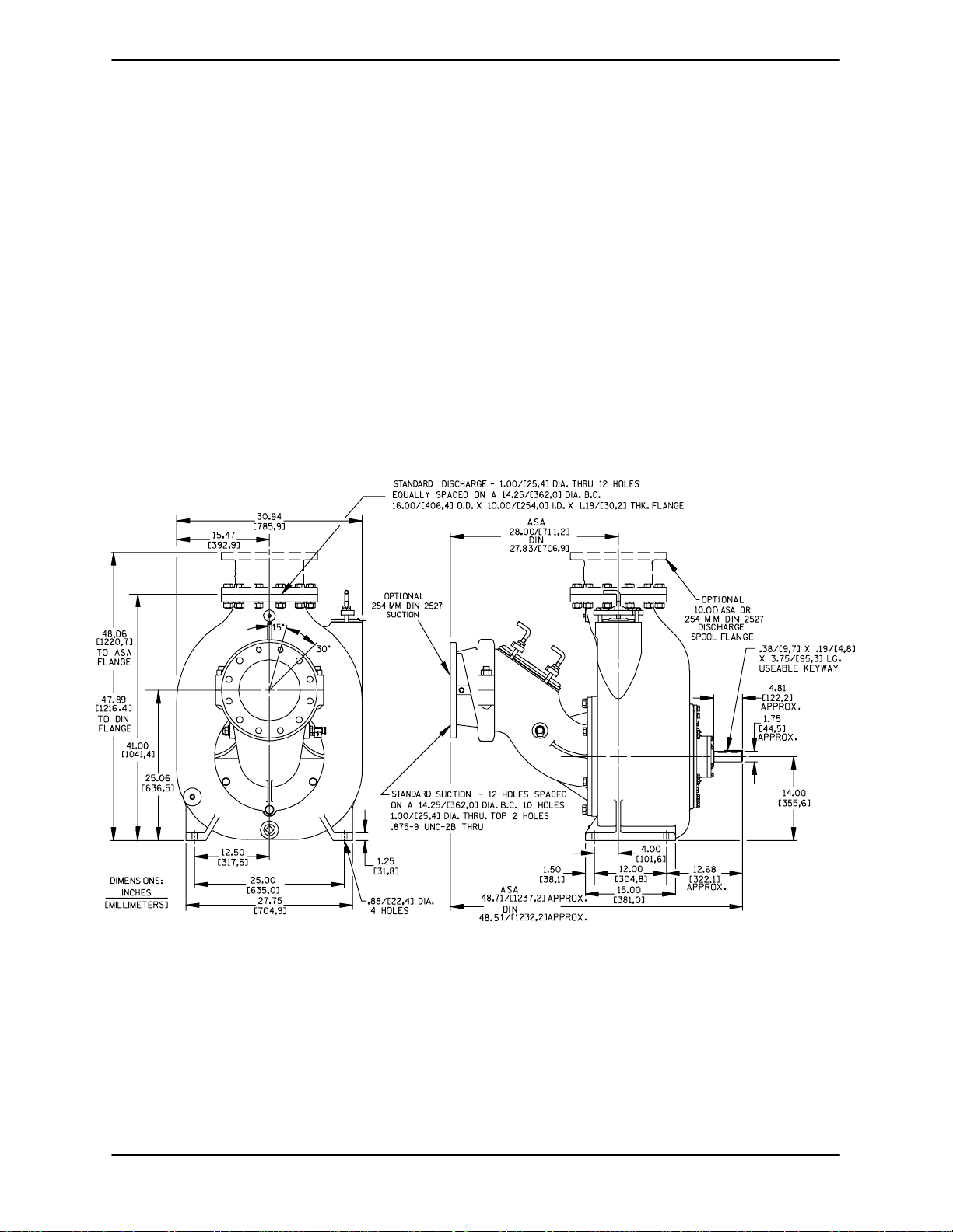
Pump Dimensions
SeeFigure1fortheapproximatephysicaldimensionsofthispump.
Figure 1. Pump Model T10A61--B
PREINSTALLATION INSPECTION
Thepump assemblywasinspected and tested beforeshipment from the factory. Before installation,
inspect the pump fordamage which may have occurred during shipment. Check as follows:
a. Inspectthe pump forcracks, dents,damaged
threads, and other obvious damage.
b. Check for and t ighten loose attaching hard-
ware. Since gaskets tend to shrink after drying, check for loose hardware at mating s urfaces.
c. Carefully read all warnings and cautions con-
tained in this manual or affixed to the pump,
and perform all duties indicated. Note the direction of rotation indicated on the pump.
PAGE B -- 1INSTALLATION
Page 8
OM--01936 TSERIES
Check that the pump shaft rotates counterclockwise when facing the impeller.
Thepumpassemblycanbeseriously
damagedifthecablesor chainsused tolift
andmovetheunitareimproperlywrapped
Only operate this pump in the direction indicated by the arrow on the pump body
and on the accompanying decal. Refer to
Rotation in OPERATION,SectionC.
d. Checklevels and lubricate as necessary. Re-
fer to LUBRICATION in the MAINTENANCE
AND REPAIRsection of this manual and perform duties as instructed.
e.Ifthepumpandpowersourcehavebeen
stored for more than 12 months, some of the
components or lubricants may have exceeded their maximum shelf life. These must
be inspected or replaced to ensure maximum pump service.
If the maximum shelf life has been exceeded, or if
anything appears to be abnormal, contact your
Gorman-Rupp distributor or the factory to determinethe repair or updating policy. Do notputthe
pump into service until appropriate action has
been taken.
POSITIONING PUMP
Lifting
around the pump.
Mounting
Locatethepump inanaccessibleplaceas closeas
practicalto the liquid being pumped. Levelmounting is essential for proper operation.
The pump may have to be supported or shimmed
to provide for level operation or to eliminate vibration.
SUCTION AND DISCHARGE PIPING
Pump performance is adversely effected by increased suction lift, discharge elevation, and friction losses. See the performance curve and operating range shown on Page E-1 to be sure your
overall application allows the pump to operate
within the safe operation range.
Materials
Either pipe or hose maybe used for suction and
discharge lines; however, the materials must be
compatiblewiththe liquidbeingpumped. If hoseis
used in suctionlines, it mustbe the rigid-wall, reinforcedtype toprevent collapse under suction.Using piping couplings in suction lines is not recommended.
Use lifting equipment with a capacity of at least
6,700 pounds. This pump weighs approximately
1,340 pounds, not including the weight of acces-
soriesor customerinstalledequipment. Customer
installed equipment such as suction and dischargepipingmust beremoved beforeattempting
to lift.
Make sure that hoists and other lifting equipment
areof sufficientcapacitytos afely handle thepump
assembly.Ifchains andcablesare used,make certain that they are positioned so that they will not
damage thepump, andso that the load willbe balanced.
PAGE B -- 2 INSTALLATION
Line Configuration
Keep suction and discharge lines as straight as
possible to minimize friction losses. Make minimum use of elbows and fittings, which substantiallyincreasefriction loss.Ifelbowsarenecessary,
use the long-radius type to minimize friction loss.
Connections to Pump
Before tightening a connecting flange, align it exactlywith t he pump port. Never pulla pipeline into
place by tightening the flange bolts and/or cou plings.
Page 9

OM--01936TSERIES
Lines near the pump must be independently supported to avoid strain on the pump which could
cause excessive vibration, decreased bearing life,
and increased shaft and seal wear. If hose-type
linesare used, theyshouldhave adequatesupport
to secure them when filled with liquid and under
pressure.
Gauges
Most pumps are drilled and tapped for installing
dischargepressureandvacuumsuctiongauges.If
these gauges are desired for pumps that are not
tapped, drill and tap the suction and discharge
lines not less than 18 inches (457 mm) from the
suction and discharge ports and install the lines.
Installationcloserto the pump may result inerratic
readings.
SUCTION LINES
Toavoidair pockets whichcouldaffect pumppriming, the suction line must be as short and direct as
possible.Whenoperationinvolvesasuctionlift,the
line must always slope upward to the pump from
the source of the liquid being pumped; if the line
slopes down to the pump at any point along the
suction run, air pockets will be created.
Fittings
three or four times the cross section of the suction
line,and that the openings willnot permit passage
of solids larger than the solids handling capability
of the pump.
Thispump is designedto handleup to 3-inch (76,2
mm) diameter spherical solids.
Sealing
Since even a slight leak will affect priming, head,
and capacity, especially when operating with a
high suction lift, all connections in the suction line
should be sealed with pipe dope to ensure an airtight seal. Follow the sealant manufacturer’s recommendations when selecting and applying the
pipe dope. The pipe dope should be compatible
with the liquid being pumped.
Suction Lines In Sumps
If a single suction line is installed in a sump, it
should be positioned away from the wall of the
sumpat a distanceequalto 1-1/2timesthediameter of the suction line.
If there is a liquid flow from an open pipe into the
sump, the flow should be kept away from the suctioninlet because the inflow willcarry air down into
the sump, and air entering the suction line will reduce pump efficiency .
Suction lines shouldbethe same sizeas the pump
inlet. If reducers are used in suction lines, they
should be the eccentric type, and should be installedwith the flat part of the reducers uppermost
to avoid creating air pockets. Valves are not normally used in suction lines, but if a valve is used,
install it w ith the stem horizontal to avoid air pockets.
Strainers
If a s trainer is furnished with the pump, be certain
touse it;any sphericalsolidswhichpass througha
strainer furnished with the pump will also pass
through the pump itself.
If a strainer is not furnished with the pump, but is
installed by the pump user, make certain that the
total area of the openings in the strainer is at least
Ifitis necessary to positioninflowcloseto the suctioninlet, installa bafflebetween theinflow and the
suctioninlet at a distance 1-1/2 times the diameter
of the suction pipe. The baffle will allow entrained
air to escape from the liquid before it is drawn into
the suction inlet.
If two suction lines are installed in a single sump,
theflow pathsmayinteract, reducingtheefficiency
of one or both pumps. To avoid this, position the
suction inlets so that they are separated by a distance equal to at least 3 times the diameter of the
suction pipe.
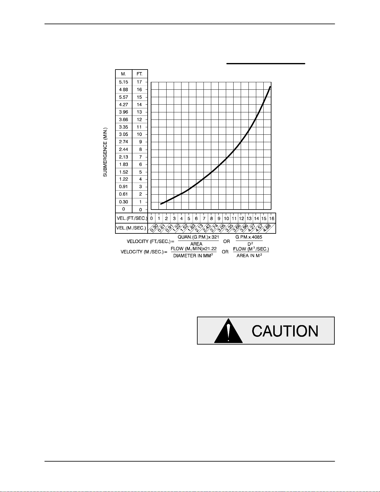
Suction Line Positioning
The depth of submergence of the suction line is
critical to efficient pump operation. Figure 2 shows
recommended minimum submergence vs. veloc-
ity.
PAGE B -- 3INSTALLATION
Page 10
OM--01936 TSERIES
NOTE
The pipe submergence required may be reduced
byinstalling a standard pipe increaser fittingatthe
endof the suctionline.The larger opening size will
reduce the inlet velocity . Calculate the required
submergence using the following formula based
on the increased opening size (area or diameter).
Figure 2. Recommended Minimum Suction Line Submergence vs. Velocity
DISCHARGE LINES
Siphoning
Donot terminate the dischargeline at a levellower
than that of the liquid being pumped unless a siphon breaker is used in the line. Otherwise, a siphoning action causing damage to the pump
could result.
Valves
A check valve in the discharge lineis normallyrecommended, but it is not necessary in low discharge head applications.
If a throttling valve is desired in the discharge line,
useavalveaslargeasthelargestpipetominimize
friction losses. Never install a throttling valve in a
suction line.
Withhighdischarge heads,it isrecommendedthat
a throttling valve and a system check valve be installed in the discharge line to protect the pump
from excessive shock pressure and reverse rotation when it is stopped.
Iftheapplicationinvolvesa highdischarge
head, gradually close the discharge
throttling valve before stopping the pump.
Bypass Lines
If it is mecessary to permit the escape of air to atmosphere during initial priming or in the repriming
cycle, install a bypass line between th epump and
thedischarge check valve. Thebypasslineshould
be sized so that it does not affect pump discharge
capacity.
ItisrecommendedthataGorman---RuppAutomatic Air Release Valve be installed in the bypass line.
PAGE B -- 4 INSTALLATION
Page 11
OM--01936TSERIES
Do Not install a manual shut---off valvein a bypass
line. If a manual shut---offvalve is installedto facilitateservice ofthe AirReleaseValve,the valvemust
not be left closed during operation. See the supplement at the end of this section for additionalinformationon bypass linesand the Gorman---Rupp
Automatic Air Release Valve.
NOTE
Thebypass line may clog occasionally, particularly
when pumping liquids containing large solids. If
clogging occurs, locate and remove theclog. Ifthe
clog is located between the discharge check valve
andtheAir ReleaseValve, thevalvewillnotclose. If
theclog is locatedin theReliefValveitself, or in the
line between the Relief Valve and the sump, the
valve will not open.
Donot terminate the dischargeline at a levellower
than that of the liquid being pumped unless a siphon breaker is used in the line; otherwise, a siphoning action could result, causing damage to
the pump.
Inlow discharge headapplications(less than30
feet or 9,1 meters), it is recommended that the bypass line be run back to thewet well, and located 6
inches (152,4 mm) below the water level or cut-off
point of the low level pump. In some installations,
this bypass line may be terminated with a six-toeight foot length of 1-1/4 inch (31,8 mm) I.D.
smooth-bore hose; air and liquid vented during
the priming process will then agitate the hose and
break up any solids, grease, or other substances
likely to cause clogging.
A bypass line that is returned to a wetwell
must be secured againstbeing d rawn into
the pump suction inlet.
this will reduce overall pumping efficiency. There-
fore, it is recommended that a Gorman-Rupp
Automatic Air Release Valve be installed in the
bypass line.
Gorman-Rupp Automatic Air Release Valves are
reliable, and require minimum maintenance. See
AUTOMATICAIR RELEASE VALVEin this section
for installation and theory of operation of the Automatic Air Release Valve. Consult your GormanRupp distributor, or contact the Gorman-Rupp
CompanyforselectionofanAutomaticAirRelease
Valve to fit your application.
A manual shut-off valve should not be
installed in any bypass line. A manual
shut-off valve may inadvertently be left
closed during operation. A pump which
has lost prime may continue to operate
without reaching prime, causing dangerousoverheatingand possible explosive rupture of the pump casing. Personnel could be severely injured.
Allow an over-heated pump to cool before servicing. Do not remove plates,
covers,gauges,orfittings fromanoverheated pump. Liquid within the pump
canreachboilingtemperatures,andvaporpressure within the pumpcan cause
parts being disengaged to be ejected
with great force. After the pump cools
drain the liquid from the p ump by removing the casing drain plug. Use caution when removing the plug to prevent
injury to personnel from hot liquid.
,
It is also recommended that pipe unions be installed at each 90_ elbow in a bypass line to ease
disassembly and maintenance.
In high discharge head applications (more than
30 feet or 9,1 meters), an excessive amount of liquid may be bypassed and forced back to the wet
well under the full working pressure of the pump;
AUTOMATIC AIR RELEASE VALVE
When properly installed and correctly adjusted to
the specific hydraulic operating conditions of the
application, the Gorman-Rupp Automatic Air ReleaseValvewillpermitairtoescapethroughthebypass line, and then close automatically when the
pump is fully primed and pumping at full capacity.
PAGE B -- 5INSTALLATION
Page 12
OM--01936 TSERIES
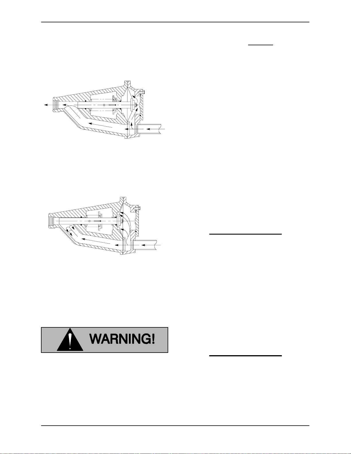
Theory of Operation
Figures 3 and 4 show a cross-sectional view of the
AutomaticAir Release Valve, and a corresponding
description of operation.
Figure 3 Valve in Open Position
Duringthe primingcycle, airfromthe pump casing
flowsthroughthebypassline,andpassesthrough
theAirReleaseValvetothewetwell(Figure3).
liters] per minute) will occur when the
valve is fully closed.Be sure
the bypass
line is directed back to the wet well or
tank to prevent hazardous spills.
Whenthe pump shutsdown, thespring returnsthe
diaphragm to its original position. Any solids that
mayhave accumulatedin the diaphragm chamber
settle to the bottom and are flushedout during the
next priming cycle.
NOTE
The valve will remain open if the pump does not
reach its designed capacity or head. V alveclosing
pressureis dependentupon thedischargeheadof
the pump at full capacity. The range of the valve
closing pressure is established by the tensionrate
ofthespringasorderedfrom thefactory.Valveclosing pressure can be further adjusted to the exact
system requirements by moving the spring retaining pin up or down the plunger rod to increase or
decrease tension on the spring. Contact your Gorman-Rupp distributor or the Gorman-Rupp Company for information about an Automatic Air Release Valve for your specific application.
Figure 4 Valve in Closed Position
When the pump is fully primed, pressure resulting
from flow against the valve diaphragm compresses the spring and closesthe valve(Figure 4).
The valve will remain closed, reducing the bypass
ofliquidto 1to5 gallonsper minute,untilthepump
loses its prime or stops.
Some le akage (1 to 5 gallons [3.8 to 19
Air Release Valve Installation
The A utomatic Air Release Valve must be inde pendently mounted in a horizontal position and
connected to the discharge line of the self-priming
centrifugal pump (see Figure 5).
NOTE
IftheAirReleaseValveistobeinstalledonastaged
pump application, contact the factory for specific
installationinstructions.
PAGE B -- 6 INSTALLATION
Page 13

OM--01936TSERIES
INSTALL AIR RELEASE VALVE
IN HORIZONTAL POSITION
90_ LONG
RADIUS
ELBOW
BLEED LINE 1”
(25,4 MM) DIA. MIN.
(CUSTOMER FUR NISHED)EXTEND 6”
(152 MM) BELOW
PUMP OFF LIQUID
LEVEL
SUPPORT
BRACKET
CLEAN-OUT
COVER
SUCTION
LINE
WET WELL
OR SUMP
DISCHARGE PIPE
DISCHARGE
CHECK VALVE
PUMP DISCHARGE
SELF-PRIMING
CENTRIFUGAL
PUMP
Figure 5. Typical Automatic Air Release Valve Installation
The valve inlet line must be installed between the
pumpdischargeportandthenon-pressurizedside
of the discharge check valve. The valve inlet is at
thelargeendofthevalvebody,andisprovided
with standard 1 inch NPT pipe threads.
The valve outlet is located a t the opposite end of
the valve, and is also equipped with standard 1
inch NPT pipe threads. The outlet should be connectedto a bleedline whichslopes back to thewet
well or sump. The bleed line must be the samesize
asthe inletpiping,orlarger.Ifpipingisusedfor the
bleed line, avoid the use of elbows whenever possible.
NOTE
It is recommended that each Air Release Valve be
fitted with an independent bleeder line directed
back to the wet well. If multiple Air Release Valves
areinstalledinasystem,theymust be fitted withindependent bleeder lines; never use a common
manifold pipe. Contact your Gorman-Rupp distributor or the Gorman-RuppCompany for information about installation of an Automatic Air Release
Valvefor your specific application.
ALIGNMENT
Thealignment of the pumpand itspower source is
critical for trouble-free mechanical operation. In
either a flexible coupling or V-belt driven system,
thedriver and pumpmustbe mounted soth attheir
shaftsare aligned with andparallel toeach other.It
is imperative that alignment be checked after the
pump and piping are installed, and before operation.
NOTE
Check Rotation, Section C, before final alignment
of the pump.
Whenmountedatthe Gorman-Ruppfactory,driver
andpumparealignedbeforeshipment.Misalignment will occur in transit and handling. Pumps
must be checked and realigned before operation.
Beforechecking alignment, tighten the foundation
bolts. The pump casing feet and/or pedestal feet,
andthedrivermountingboltsshouldalsobetightly
secured.
PAGE B -- 7INSTALLATION
Page 14

OM--01936 TSERIES
ARA
A
V
When checking alignment, disconnect
the power source to ensure that the
pump will remain inoperative.
Figure6B. AligningNon-SpiderTypeCouplings
Adjusting the alignment in one direction
may alter the alignment in another direction. check each procedure after altering
alignment.
Coupled Drives
When using couplings, the axis of the power
source must be aligned to the axis of the pump
shaft in both the horizontal and vertical planes.
Mostcouplings requirea specificgap or clearance
between the drivingand the driven shafts. Refer to
the coupling manufacturer’s service literature.
Alignspiderinserttypecouplingsby usingcalipers
to measure the dimensions on the circumference
of the outer ends of the coupling hub every 90 degrees. The coupling is in alignment when the hub
ends are the same distance apart at all points (see
Figure 6A).
Align non-spider type couplings by using a feeler
gaugeortaper gaugebetweenthecouplinghalves
every 90 degrees. The coupling is in alignment
whenthehubsarethesamedistanceapartatall
points (see Figure 6B).
Checkparalleladjustmentby layingastraightedge
across both coupling rims at the top, bottom, and
side. When the straightedge rests evenly on both
halves of the coupling, the coupling is inhorizontal
parallel alignment. If the coupling is misaligned,
use a feeler gauge between the coupling and the
straightedge to measure the amount of misalignment.
V-Belt Drives
When using V-belt drives, the power source and
the pump must be parallel. Use a straightedge
alongthesidesofthe pulleystoensurethat thepulleys are properly aligned (see Figure 6C). In drive
systemsusing twoormorebelts,make certainthat
the belts are a matched set; unmatched sets will
cause accelerated belt wear.
Figure 6A. Aligning Spider-Type Couplings
MISALIGNED:
SHAFTS
NOT P
LLEL
Figure 6C. Alignment of V-Belt Driven Pumps
MISALIGNED:
SHAFTS
NOT IN LINE
ALIGNED:SHAFTS
PARALLEL AND
SHE
ES IN LINE
PAGE B -- 8 INSTALLATION
Page 15

Tightenthe beltsinaccordancewiththe beltmanufacturer’s instructions. If the belts are too loose,
they will slip; if the belts are too tight, t here willbe
excessivepower loss and possible bearing failure.
Select pulleys that will match the proper speed ratio; overspeeding the pump may damage both
pump and power source.
OM--01936TSERIES
Do not operate the pump without the
guard in place over the rotating parts.
exposed rotating parts can catch clothing, fingers,or tools,causing severe injury to personnel.
PAGE B -- 9INSTALLATION
Page 16

TSERIES
OM--01936
OPERATION --- SECTION C
Review all SAFETY information in Section A.
Follow the instructions on all tags, labels and decals attached to the pump.
This pump is designed to handle mild
industrialcorrosives,residues and slurries containing large entrained solids.
Do not attempt to pump volatile, corrosive, or flammable materials which may
damage the pump or endanger personnel as a result of pump failure.
Pump speed and operating condition
points must be within the continuous performance range shown on the curve.
(See Section E, Page 1.)
1. The pump is being put into service for the
first time.
2. Thepump has notbeen usedfor aconsiderable length of time.
3. The liquid in the pump casing has evaporated.
Once the pump casing has been filled, the pump
will prime and reprime a s necessary.
After filling the pump casing, reinstall
and tighten the fill plug. Do not attempt
to operate the pump unless all connecting piping is securely installed. Otherwise, liquid in the pump forced out
under pressure could cause injury to
personnel.
Tofill the pump, remove the pump casing fill cover
or fill plug in the top of the casing, and add clean
liquid until the casing is filled. Replace the fill cover
or fill plug before operating the pump.
PRIMING
Install the pump and piping as described in INSTALLATION. Make sure that the piping connec-
tions are tight, and that the pump is securely
mounted. Check that the pump is properly lubricated (see LUBRICATION in MAINTENANCE
AND REPAIR).
This pump is self-priming, but the pump should
never be operated unless there is liquid in the
pump casing.
Never operate this pump unless there is
liquid in the pump casing. The pump will
notprime when dry.Extended operationof
a dry pump will destroythe seal assembly.
Add liquid to the pump casing when:
STARTING
Consult the operations manual furnished with the
power source.
OPERATION
Lines With a Bypass
Ifa Gorman-RuppAutomatic AirRelease Valvehas
been installed, the valve will automatically open to
allow the pump to prime, and automatically close
after priming is complete (see INSTALLATION for
Air Release Valve operation).
If the bypass line is open, air from the suction line
willbe discharged through the bypass line back to
thewetwellduringtheprimingcycle.Liquidwill
then continue to circulate through the bypass line
while the pump is in operation.
Lines Without a Bypass
Open all valves in the discharge line and start the
power source. Priming is indicated by a positive
OPERATION PAGE C -- 1
Page 17

OM--01936
reading on the discharge pressure gauge or by a
quieteroperation.The pump may not primeimmediately because the suction line must first fill with
liquid. If the pumpfails to prime withinfiveminutes,
stop it and check the suction line for leaks.
Afterthepump has beenprimed, partiallyclosethe
discharge line throttling valve in order to fill the line
slowly and guard against excessive shock pressure which could damage pipe ends, gaskets,
sprinkler heads, and any other fixtures connected
to the line. When the discharge line is completely
filled,adjustthethrottlingvalve tothe requiredflow
rate.
Do not operate the pump against a
closed discharge throttling valve for
longperiodsof time.Ifoperatedagainst
a closed discharge throttling valve,
pump components will deteriorate, and
the liquid could come to a boil, build
pressure,and cause the pumpcasing to
rupture or explode.
Leakage
No leakage should be visible at pump mating surfaces, or at pump connections or fittings. Keep all
lineconnectionsand fittingstight to maintainmaxi mum pump efficiency.
Liquid Temperature And Overheating
TSERIES
Do not remove plates, covers, gauges,
pipe plugs, or fittings from an over heated pump. Vapor pressure within
the pump can cause parts being disengagedto be ejected withgreat force. Allow the pump to cool before servicing.
Asa safeguard against rupture orexplosiondueto
heat, this pump is equipped with a pressure relief
valve which will open if vapor pressure within the
pumpcasing reaches a critical point. Ifoverheating
does occur, stop the pump immediately and allow
it to cool before servicing it. Approach any over-
heated pump cautiously. It is recommended that
the pressure relief valve assembly be replaced at
each overhaul, or any time the pump casing overheats and activates the valve. Never replace this
valve with a substitute which has not been specified or provided by the Gorman-Rupp Company.
Strainer Check
If a suction strainer has been shipped with the
pump or installed by the user, check the strainer
regularly, and clean it as necessary. The strainer
shouldalsobe checked ifpump flowratebegins to
drop. If a vacuum suction gauge has been installed, monitor and record the readings regularly
to detect strainer blockage.
Never introduce air or steam pressure into the
pump casingorpipingto removea blockage. This
could result in personal injury or damage to the
equipment. If backflushing is absolutely necessary, liquid pressure must be limited to 50% of the
maximum permissible operating pressure shown
on the pump performance curve.
The maximum liquid temperature for this pump is
160_F(71_C). Do not apply it at a higher operating
temperature.
Overheating can occur if operated with the valves
in the suction or discharge lines closed. Operating
against closed valves could bring the liquid to a
boil, build pressure, and cause the pump to rupture or explode. If overheating occurs, stop the
pump and allow it to cool before servicing it. Refill
the pump casing with cool liquid.
Pump Vacuum Check
Withthe pump inoperative,installa vacuumgauge
in the system, using pipe dope on the threads.
Block the suction line and start the pump. At operating speed the pump should pull a vacuum of 20
inches (508 mm) or more of mercury. If it does not,
check forairleaks in the seal,gasket, ordischarge
valve.
Openthe suctionline, and readthe vacuum gauge
with the pump primed and at operation speed.
OPERATIONPAGE C -- 2
Page 18

TSERIES
OM--01936
Shut offthe pump. The vacuum gauge readingwill
immediately drop proportionate to static suction
lift,andshouldthenstabilize.Ifthe vacuumreading
falls off rapidly after stabilization, an air leak exists.
Before checking for the source of the leak, check
the point of installation of the vacuum gauge.
STOPPING
Never halt the flow of liquid suddenly. If the liquid
being pumped is stopped abruptly, damaging
shock waves can be transmitted to the pump and
piping system. Close all connecting valves slowly.
On engine driven pumps, reduce the throttle
speed slowly and allow the engine toidlebrieflybefore stopping.
If the application involves a highdischarge
head, gradually close the discharge
throttling valve before stopping the pump.
After stopping the pump, disconnect or lock out
the power source or take other action to ensure
that the pump will remain inoperative.
Cold Weather Preservation
In below freezing conditions, drain the pump to
preventdamage fromfreezing.Also, clean outany
solids by flushing with a hose. Operate the pump
for approximately one minute; this willremove any
remaining liquid that could freeze the pump rotat-
ing parts. If the pump will be idle for more than a
few hours, or if it has been pumping liquids containing a large amount of solids, drain the pump,
and flush it thoroughly with clean water. Toprevent
large solids from clogging the drain port and preventing the pump from completely draining, insert
a rod or stiff w ire in the drain port, and agitate the
liquid during the draining process. Clean out any
remaining solids by flushing with a hose.
BEARING TEMPERATURE CHECK
Bearingsnormallyrun at higher than ambient temperatures because of heat generated by friction.
Temperatures up to 160_F(71_C) are considered
normalforbearings,and theycan operatesafelyto
at least 180_F(82_C).
Checkingbearingtemperatures byhand isinaccurate. Bearing temperatures can be measured accurately by placing a contact-type thermometer
against the housing. Record this temperature for
future reference.
A sudden increase in bearing temperature is a
warning that t he bearings are at the point offailing
to operate properly. Make certain that the bearing
lubricant is of the proper viscosity and at the correct level (see LUBRICATION in MAINTENANCE
AND REPAIR). Bearing overheating can also be
caused byshaft misalignmentand/or excessivevibration.
When pumps are first started, the bearings may
seem to run at temperatures a bove normal. Con tinued operation should bring the temperatures
down to normal levels.
OPERATION PAGE C -- 3
Page 19

TROUBLESHOOTING --- SECTION D
Review all SAFETY information in Section A.
Beforeattempting to open or service the
pump:
1. Familiarizeyourselfwiththis manual.
2. Disconnect or lock out the power
source,ortake other actiontoensure
that the pump will remain inoperative.
3. Allow the pump to completely cool if
overheated.
4. Ventthe pump slowly and cautiously.
5. Close the suction and discharge
valves.
6. Check the temperature before opening any covers, plates, or plugs.
7. Drain the pump.
OM--01936TSERIES
Table 1. Trouble Shooting Chart
TROUBLE
PUMP FAILS TO PRIME Not enough liquid in casing.
PUMP STOPS OR FAILS
TO DELIVER RATED
FLOW OR PRESSURE
POSSIBLE CAUSE PROBABLE REMEDY
Suctioncheck valve contaminated or
damaged.
Air leak in suction line.
Lining of suction hose collapsed.
Leakingorwornsealorpumpgas-
ket.
Suction lift or discharge head too
high.
Strainer clogged.
Air leak in suction line.
Lining of suction hose collapsed.
Addliquidtocasing.SeePRIMING.
Clean or replace check valve.
Correct leak.
Replace suction hose.
Check pump vacuum. R eplace leak-
ingorwornsealorgasket.
Check piping installation and install
bypass line if needed. See INSTAL-
LATION.
Check strainer and clean if necessary.
Correct leak.
Replace suction hose.
TROUBLESHOOTING PAGE D -- 1
Page 20

OM--01936 TSERIES
Table 1. Trouble Shooting Chart (cont.)
TROUBLE POSSIBLE CAUSE PROBABLE REMEDY
PUMP STOPS OR FAILS
TO DELIVER RATED
FLOW OR PRESSURE
(cont.)
PUMP REQUIRES TOO
MUCH POWER
Leakingorwornsealorpumpgasket.
Strainer clogged.
Suction intake not submerged at
proper level or sump too small.
Impellerorotherwearingparts
worn or damaged.
Impeller clogged.
Discharge head too high.
Suction lift too high.
Pump speed too slow.
Pump speed too high.
Discharge head too low.
Check pump vacuum. Replace
leakingorwornsealorgasket.
Check strainer and clean if necessary.
Check installation and correct submergence as needed.
Replace worn or damaged parts.
Check that impeller is properly centered and rotates freely.
Free impeller of debris.
Install bypass line.
Measure lift w/vacuum gauge. Re-
duce lift and/or friction losses in
suction line.
Check engine output; consult engine operation manual.
Check engine output.
Adjust discharge valve.
Liquid solution too thick.
Bearing(s) frozen.
PUMP CLOGS
FREQUENTLY
EXCESSIVE NOISE Cavitation in pump.
Discharge flow too slow.
Suction check valve or foot valve
clogged or binding.
Liquid solution too thick.
Pumping entrained air.
Pump or drive not securely
mounted.
Impeller clogged or damaged.
Dilute if possible.
Disassemble pump and check
bearing(s).
Open discharge valve fully to in-
crease flow rate, and run engine at
maximum governed speed.
Clean valve.
Dilute if possible.
Reduce suction lift and/or friction
losses in suction line. Record vacu-
um and pressure gauge readings
and consult local representative or
factory.
Locate and eliminate source of air
bubble.
Secure mounting hardware.
Clean out debris; replace damaged
parts.
TROUBLESHOOTINGPAGE D -- 2
Page 21

TROUBLE POSSIBLE CAUSE PROBABLE REMEDY
BEARINGS RUN TOO
HOT
Table 1. Trouble Shooting Chart (cont.)
Bearing temperature is high, but
within limits.
Check bearing temperature regular-
ly to monitor any increase.
OM--01936TSERIES
Low or incorrect lubricant.
Suction and discharge lines not
properly supported.
Drive misaligned.
PREVENTIVE MAINTENANCE
Sincepump applicationsareseldom identical,and
pump wear is directly affected by such things as
the abrasive qualities, pressure and temperature
oftheliquidbeingpumped, thissectionisintended
only to provide general recommendations and
practices for preventive maintenance. Regardless
of the application however, following a routine preventive maintenance schedule will help assure
trouble-free performance and long life from your
Gorman-Rupp pump. For specific questions concerning your application, contact your GormanRupp distributor or the Gorman -Rupp Company.
Record keeping is an essential component of a
good preventive maintenance program. Changes
in suction and discharge gauge readings (if so
Check for proper type and level of
lubricant.
Check piping installation for proper
support.
Align drive properly.
equipped) between regularly scheduled inspections can indicate problems that can be corrected
before system damage or catastrophic failure occurs.The appearanceof wearingparts shouldalso
bedocumented at eachinspection forcomparison
as well. Also, if records indicate that a certain part
(such as the seal) fails at approximately the same
duty cycle, the part can be checked and replaced
beforefailureoccurs,reducing unscheduleddown
time.
For new applications, a first inspection of wearing
partsat250 hourswillgiveinsightintothe wearrate
foryourparticularapplication.Subsequentinspections should be performed at the intervals shown
on the chart below. Critical applications should be
inspected more frequently.
TROUBLESHOOTING PAGE D -- 3
Page 22

OM--01936 TSERIES
Preventive Maintenance Schedule
Service Interval*
Item
General Condition (Temperature, Unusual
Noises or Vibrations, Cracks, Leaks,
Loose Hardware, Etc.) I
Pump Performance (Gauges, Speed, Flow) I
Bearing Lubrication I R
Seal Lubrication (And Packing Adjustment,
If So Equipped) I R
V-Belts (If So Equipped) I
Air Release Valve Plunger Rod (If So Equipped) I C
Front Impeller Clearance (Wear Plate) I
Rear Impeller Clearance (Seal Plate) I
Check Valve I
Pressure Relief Valve (If So Equipped) C
Pump and Driver Alignment I
Shaft Deflection I
Bearings I
Bearing Housing I
Piping I
Driver Lubrication --- See Mfgr’s Literature
Daily Weekly Monthly Semi-
Annually
Annually
Legend:
I = Inspect, Clean, Adjust, Repair or Replace as Necessary
C= Clean
R= Replace
* Service interval based on an intermittent duty cycle equal to approximately 4000 hours annually.
Adjust schedule as required for lower or higher duty cycles or extreme operating conditions.
TROUBLESHOOTINGPAGE D -- 4
Page 23

TSERIES
OM--01936
PUMP MAINTENANCE AND REPAIR --- SECTION E
MAINTENANCE AND REPAIR OF THE WEARING PARTS OF THE PUMP WILL MAINTAIN PEAK
OPERATING PERFORMANCE.
STANDARD PERFORMANCE FOR PUMP MODEL T10A61--B
Based on 70_F(21_C) clear water at sea level
with minimumsuction lift. Since pump installations
areseldomidentical,yourperformancemaybedifferent due to such factors as viscosity, specific
gravity, elevation, temperature, and impeller trim.
Contact the Gorman-RuppCompany to verify performance or part numbers.
Pump speed and operating condition
If your pump serial number is followed by an “N”,
your pump is NOT astandardproductionmodel.
MAINTENANCE & REPAIR PAGE E -- 1
points must be within the continuous performance range shown on the curve.
Page 24

OM--01936 TSERIES
SECTION DRAWING
Figure E---1. Pump Model T10A61---B, /FM, /WW
MAINTENANCE & REPAIRPAGE E -- 2
Page 25

TSERIES
OM--01936
PARTS LIST
(From S/N 806819 up)
Pump Model T10A61---B, /FM, /WW
Ifyourpump serial number is followedby an “N”,your pump is NOT a standard production model. Contact
the Gorman-Rupp Company to verify part numbers.
ITEM
PART NAME PART
NO.
NUMBER
MAT’L
CODE
QTY ITEM
NO.
PART NAME PART
NUMBER
MAT’L
CODE
QTY
1 PUMP CASING 38222---701 10010 1
2 REPAIR ROTATING ASSY 44163---064 --- --- --- 1
/WW REPAIR ROT ASSY 44163---247 ------ --- 1
3 CHECK VALVE ASSY 46421---037 --- --- --- 1
4 ---CHECK VALVE BODY 38341---805 10010 1
5 ---PIPE PLUG P08 15079 1
6
---CHECK VALVE 46411---082 24010 1
7
---PIVOT CAP 38141- --003 11060 2
8 ---HEX HD CAPSCREW B0606 17000 2
9 ---LOCKWASHER AK06 17000 2
10 ---FLAT WASHER KB08 17090 2
11 SHOULDER TYPE CPLG 25552---213 --- ------ 1
12
CLEANOUT CVR GSKT 38688---008 20000 1
13 CLAMP BAR 38111---004 11010 2
14 MACHINE BOLT A1014 15991 4
15 CLAMP BAR SCREW 31912---009 15000 2
16 CLEANOUT CVR ASSY 48271---018 --- --- --- 1
17 PIPE PLUG P04 15079 1
18 DISCH STICKER 6588BJ --- --- --- 1
19 NAMEPLATE 38818---040 13990 1
20 DRIVE SCREW BM#04---03 17000 4
21
SHIM SET 48261---056 --- --- --- 6
22 CASING RING 31281---016 15990 1
23 HEX HD CAPSCREW B0806 15991 6
24 LOCKWASHER J08 15991 6
25 HEX HD CAPSCREW B0805 15991 6
26 LOCKWASHER J08 15991 6
27 FILL CVR PLATE ASSY 42111---344 --- ------ 1
28 ---FILL CVR PLATE NOT AVAILABLE 1
29 ---WARNING PLATE 38816---097 13990 1
30 ---DRIVE SCREW BM#04---03 17000 2
31 ---FILL COVER GASKET 50G 19210 1
32 CLAMP BAR SCREW 31912---009 15000 1
33 MACHINE BOLT A1014 15991 2
34 CLAMP BAR 38111---004 11010 1
35 ROTATION DECAL 2613M --- --- --- 1
36
BRG HSG O-RING S1914 --- ------ 1
37
SEAL END PLT O-RING S1914 --- ------ 1
38
FRONT WEAR PLATE 38691---826 17070 1
39 PIPE PLUG P08 15079 1
40
SUCTION HD GASKET 38682---811 20000 1
41 PIPE PLUG P24 10009 1
42 HEX HD CAPSCREW B1408 15991 2
43 LOCKWASHER J14 15991 2
44 HEX HD CAPSCREW B1207 15991 4
45 LOCKWASHER J12 15991 4
46 PRESS RELIEF VLV 46431---803 ------ --- 1
INDICATES PARTSRECOMMENDED FOR STOCK
[ OPTIONAL MECHANICAL SEAL(S) MUST BE USED WITH MECHANICAL SEAL SHAFT SLEEVE OR SOLID SST SHAFT.
47 RED PIPE BUSHING AP2008 11999 1
48 PIPE PLUG P20 10009 1
49 SUCTION HEAD 38246---609 10010 1
50 SUCTION STICKER 6588AG ------ --- 1
NOT SHOWN:
FILL HR PRIME STK 6588AH ---- -- --- 1
LUB DECAL 11421 --- --- --- 1
INSTRUC LABEL 2613DK ---- -- --- 1
WARNING DECAL 2613FE --- --- --- 1
WARNING DECAL 38816---302 --- ------ 1
OPTIONAL:
DISASSEMBLYTOOL 12858 24000 1
ADI WEARPLATE 38691---826 1102H 1
ASTL WEARPLATE 46451---750 24160 1
ADI REPAIR ROT ASSY 44163---233 ---- -- --- 1
10” SPOOL FLANGE 38642---607 10000 1
/FM FLANGE KIT 48213- --080 --- ------ 1
/FM FLANGE KIT 48213- --084 --- ------ 1
/WW SUCT FLANGE 38341---805 10010 1
PRESSURE RELIEF VALVES:
---SEWAGE TYPE 46431---628 --- --- --- 1
---STAINLESS STEEL 26662---101 --- --- --- 1
CASING HEATERS:
---120V 47811---014 --- --- --- 1
---240V 47811---015 --- --- --- 1
CHECK VALVE ASSYS:
---NEO MOLDED TYPE 46411---082 --- --- --- 1
n ---VITON MOLDED 46411---081 ------ --- 1
HI TEMP SHUT-DOWN KITS:
---145ºF 48313---186 --- --- --- 1
---130ºF 48313---256 --- --- --- 1
---120ºF 48313---257 --- --- --- 1
HI TEMP SHUT-DOWN 48313---172 --- --- --- 1
THERMOSTAT KIT 145ºF
AIR RELEASE VALVES:
--- 10 # CO MP SP R ING GRP33 --- 0 7 A --- --- --- 1
--- 25 # CO MP SP R ING GRP33 --- 0 7 --- --- --- 1
--- 80 # CO MP SP R ING GRP33 --- 0 7 B --- --- --- 1
BRG HOUSING O -RING
n ---VITON 25154---458 --- --- --- 1
n KALREZr AND VITONt ARE PRODUCTS OF THE DUPONT CORP
L AFLASr IS A PRODUCTOF THE 3M CORP
MAINTENANCE & REPAIR PAGE E -- 3
Page 26

OM--01936 TSERIES
SECTION DRAWING
Figure E-2. 44163---064 And 44163---247 WW Repair Rotating Assembly
MAINTENANCE & REPAIRPAGE E -- 4
Page 27

TSERIES
OM--01936
PARTS LIST
44163---064 And 44163---247 Repair Rotating Assembly
Note: Order complete Repair Rotating Assemby for /WW model from the Pump Model Assembly Parts List
on page E---3. Repair Rotating Assembly for /WW model includes all of the standard parts listed below.
ITEM
PART NAME PART
NO.
NUMBER
MAT’L
CODE
QTY ITEM
NO.
PART NAME PART
NUMBER
MAT’L
CODE
QTY
1 IMPELLER 38615---014 17070 1
SEAL ASSEMBLY 46512---192 --- --- --- 1
2
3 SEAL END PLATE 38272---228 17070 1
SEAL PLATE GSKT 38684---302 19140 1
4
BEARING O-RING S1874 --------- 1
5
6 BEARING HOUSING 38251---506 10010 1
7 VENTED SEAL PLUG 38649---009 15079 1
8 VENTED BRG PLUG 38649---009 15079 1
9
BR G HO U SING O -RI N G S333 --- --- --- 1
10 HEX HD CAPSCREW B0605 1/2 15991 6
11 LOCKWASHER J06 15991 6
12
BALL BEARING 23422---412 --- --- --- 1
13 RE TAIN ING RING S2 15 --- --- --- 1
IMPELLER SHAFT KEY N0612 15990 1
14
OIL SEAL S1917 --- ------ 1
15
16 OIL LEVEL SIGHT GAUGE S1471 --- --- --- 1
17 BEARING CAP 38322---415 10010 1
18 BRG DRAIN PLUG P12 15079 1
19 SEAL DRAIN PLUG P12 15079 1
20
IMPELLER SHAFT 38515---548 1706H 1
BALL BEARING 23421---461 --- --- --- 1
21
22 HEX HD CAPSCREW B0808 17000 4
23 LOCKWASHER J08 17000 4
24
OIL SEAL S1917 --- ------ 1
IMPELLER WASHER 10278 17090 1
25
26
IMPELLER CAPSCREW DM1004S 17090 1
27 PIPE PLUG P12 15079 1
IMPELLER SHIM SET 5091 17090 REF
28
SEAL END PLATE O-RING S1914 --- --- --- 1
29
30
BRG HOUSING O-RING S1914 ------ --- 1
ROT ASSY SHIM SET 48261---056 --- --- --- 6
31
32 SHIPPING PLUG 11495D 15079 1
33 SHIPPING PLUG 11495D 15079 1
NOT SHOWN:
ROTATION DECAL 2613M --- --- --- 1
INSTRUCTION TAG 6588U --- --- --- 1
OPTIONAL:
ADI IMPELLER 38615---014 1102H 1
ADI SEAL END PLATE 38272---413 1102H 1
ROTATINGASSY O-RING:
n ---VITON 25154---458 --- --- --- 1
PERMALON SEAL 46512---189 --- ------ 1
[ METAL BELLOWS MECH SEAL ASSY
[LAFLAS SEAL 46512---193 --- --- --- 1
[ METAL BELLOWS MECH SEAL ASSY
n (KALREZ) 46512---183 ------ --- 1
INDICATES PARTSRECOMMENDED FOR STOCK
[ OPTIONAL MECHANICAL SEAL MUST BE USED WITH MECHANICAL SEAL SHAFT SLEEVE OR /WWS SOLID SST SHAFT.
n KALREZr AND VITONt ARE PRODUCTS OF THE DUPONT CORP
L AFLASr IS A PRODUCTOF THE 3M CORP
MAINTENANCE & REPAIR PAGE E -- 5
Page 28

OM--01936 TSERIES
PUMP AND SEAL DISASSEMBLY
AND REASSEMBLY
Review all SAFETY information in Section A.
Followtheinstructionsonall tags,label anddecals attached to the pump.
This pump requires little service due to its rugged,
minimum-maintenance design. However, if it becomesnecessarytoinspect orreplace thewearing
parts, follow these instructions which are keyed to
the sectional views (see Figures E-1 and E-2) and
the accompanying parts lists.
As described on the following pages, this manual
willalert personnel to known procedures which require special attention, to those which could damage equipment, and to those which could be dangeroustopersonnel. However, this manualcannot
possibly anticipate and provide detailed precautions for every situation that might occur during
maintenanceof theunit. Therefore, itistheresponsibilityof the owner/maintenance personnel to ensure that only safe, established maintenance proceduresare used, andthat anyproceduresnotaddressedinthis manualareperformedonlyafterestablishingthat neitherpersonalsafetynor pumpintegrity are compromised by such practices.
Many service functions may be performed by
drainingthe pumpa nd removingthe suctionhead.
Ifmajor repairisrequired, thepiping and/orengine
must be disconnected. The following instructions
assume complete disassembly is required.
sure that the pump will remain inoperative.
3. Allow the pump to completely cool
if overheated.
4. Check the temperature before
opening any covers, plates, or
plugs.
5. Close the suction and discharge
valves.
6. Vent the pump slowly and cautiously.
7. Drain the pump.
Use lifting and moving equipment in
good repair and with adequate capacity
toprevent injuries to personnelor damage to equipment. Suction and discharge hoses and piping must be removed from the pump before lifting.
Cleanout Access And Suction Check Valve
Removal
(Figure E-1)
Beforeattemptingtoservicethe pump,removethe
casing drain plug (21) and drain the pump. Clean
and reinstall the drain plug.
Forcleanout access, loosen the clamp screws (41)
and clamp bars (40) securing the cleanout cover
(39) to the suction head (26).
Beforeattemptingtoservicethe pump,disconnect
orlock out the power source or take other action to
ensure that the pump will remain inoperative.
Close all valves in the suction and discharge lines.
Beforeattemptingto open orservice the
pump:
1. Familiarize yourself with this manual.
2. Disconnect or lock out the power
source, or take other action to en-
To remove the check valve assembly, reach
through the cleanout opening and remove the
hardware (35, 36 and 37) securing the check valve
(31) to the valve body (33) and suction head.
Replace the cleanout cover gasket (38) before reinstalling the cover.
Suction Head And Wear Plate Removal
(Figure E-1)
To remove the suction head, support it with a s uitablehoist and slingand remove the hardware (22,
23, 24 and 25) securing it t o the pump casing. Remove the suction head gasket (20).
MAINTENANCE & REPAIRPAGE E -- 6
Page 29

TSERIES
OM--01936
If the wear plate (19) does not slide easily fromthe
casing bore, install capscrews (1/2-13 UNC X 1
inch long, not supplied) in the tapped holes provided. Using a suitable puller, remove it from the
casing.
Rotating Assembly Removal
(Figure E-2)
Therotatingassemblymayberemovedfromeither
side of the casing; however , it is recommended
that it be removedt hrough the suction head opening.
Theimpeller (1)should beloosenedwhiletherotating assembly is still secured to the pump casing.
Before loosening the impeller,removethesealcavitydrain plug (19) and draintheseal lubricant. This
willprevent the oil in the seal cavity from escaping
as the impellerisloosened.Cleanand reinstallthe
seal cavity drain plug.
Immobilize the impeller by wedging a block of
wood between the vanes and remove the impeller
capscrew and washer (25 and 26). Install a lathe
dog on the drive end of the shaft (16) with the “V”
notch positioned over the shaft keyway. Strike the
lathe dog sharply in a counterclockwise direction
(when facing the drive end of the shaft). When the
impeller breaks loose,remove thewood block and
lathe dog. Do not fully unscrew the impeller from
the shaft at this time.
(Figure E-1)
An optional disassembly tool for removing and installing the rotating assembly is available from the
factory. If improvised tools are used, be sure they
areheavy enoughfor safeuseand willnotdamage
the pump.
Remove the inner hardware (11 and 12) from the
casing ring (15). If the removal tool is used, follow
theinstructionspackagedwith it,andpull therotating assembly from the pump casing (see Figure
E-3 for removal tool use). If the removal tool is not
used, install three of the inner capscrews in the
jacking holes in the casing ring, and use them to
press the rotating assembly into the pumpcasing
until the bearing housing is free.
Remove the jacking screws from the casing ring.
Remove the outer hardware (13 and 14) and shim
sets (16). Separate the casing ring from the pump
casing. Tie and tag the shim s ets for ease of reassembly.
After the rotating assembly is loosened, screw a
5/8-11 U NC X 16 inch long threaded rod into the
hole in the impeller shaft. Support the drive end of
the shaft with a 1-13/16” (46 mm) minimum I.D.
pieceofpipeorasetofhandlesasshowninFigure
E-3, and slide the complete rotating assembly
through the suction head opening. Once free, use
a suitable hoist and sling and attach it to the lifting
eye provided at the top of the bearing housing to
movethe rotatingassemblyto asuitable workarea
for further disassembly.
ADD PIPE
AS REQUIRED
Figure E-3. Rotating Assembly Removal With Tool
MAINTENANCE & REPAIR PAGE E -- 7
Page 30

OM--01936 TSERIES
Impeller Removal
(Figure E-2)
Unscrew the impeller from the shaft in a counterclockwise direction(when facing the impeller). Use
caution when unscrewing the impeller; tension on
theshaft sealspring willbereleasedas the impeller
is removed.
Remove the impeller adjusting shims (28). Tieand
tag the shims or measure and record their thickness for ease of reassembly.
Seal Removal And Disassembly
(Figure E-2)
Remove the seal spring. Apply oil to the shaft and
workit up underthe bellows. Slidetherotatingportion of the seal off the shaft as a unit.
Usetwo stiff wires with hookedends to remove the
stationary portion of the seal.
is not recommended. These operations
should be performed only in a properly
equipped shop by qualified personnel.
Remove the bearing housing drain plug (18) and
drain the lubricant. Clean and reinstall the drain
plug.
Disengage the hardware (10 and 11) and remove
the bearing cap (17), O-ring (9) and oil seal (15)
from the shaft. Press the oil s eal from the bearing
cap.
Remove the bearing cap O-ring (9).
Place a block of wood against the impeller end of
theshaftandtaptheshaft(20)andassembled
bearings (12 and 21) from the bearing housing.
After removing the shaft and bearings, clean and
inspect the bearings in place as follows.
An alternate method of removing the stationary
portion of the seal is to remove the hardware (22
and 23) and separate the seal end plate (3) from
thebearinghousing(6). Removethesealend plate
and bearing housing O-rings (29 and 30). Position
theseal endplateon aflat surfacewiththe impeller
side down. Use a wooden dowel or other suitable
tooltopress on the backsideof the stationaryseat
untilthe seat, O-rings, and stationary element can
be removed.
If no further disassembly is required, refer to Seal
Installation.
Shaft and Bearing Removal and Disassembly
(Figure E-2)
When the pump is properly operated and maintained,the bearing housingshouldnot require disassembly. Disassemble the shaft and bearings
only when there is evidence of wear or damage.
To prevent damage during removal from
the shaft, it is recommended that bearings
be cleaned and inspected in place.Itis
strongly recommended that the bearings
be replaced any time the shaft and bearings are removed.
Clean the bearing housing, shaft and all component parts (except the bearings) with a soft cloth
soaked in cleaning solvent. Inspect the parts for
wear or damage and replace as necessary.
Most cleaning solvents are toxic and
flammable. Use themonly in a well ventilated area free from excessive heat,
sparks, and flame. Read and follow all
precautions printed on solventcontainers.
Shaft and bearing disassembly in the field
Clean the bearings thoroughly in fresh cleaning
solvent.Dry the bearings with filtered compressed
air and coat with light oil.
MAINTENANCE & REPAIRPAGE E -- 8
Page 31

TSERIES
Bearings must be kept free of all dirt and
foreign material. Failureto do so willgreatly shorten bearing life. Do not spin dry
bearings. This may scratch the balls or
races and cause premature bearing failure.
Rotate the bearings by hand to check for roughnessor bindingand inspectthe bearing balls. Ifrotation is rough or the bearing balls are discolored,
replace the bearings.
The bearing tolerances provide a tight press fit
onto the shaft and a snug slip fit into the bearing
housing. Replace the bearings, shaft, or bearing
housing if the proper bearing fit is not achieved.
Ifbearing replacementisrequired,remove the outboard bearing retaining ring (13), and use a bearingpulleroranarbor(orhydraulic)presstoremove
the bearings (12 and 21) from the shaft.
OM--01936
small nicks andburrs with a fine file or emery cloth.
Replace the shaft if defective.
Position the inboard oil seal (24) in the bearing
housing bore with the lip positioned as shown in
Figure E-2. Press the oil seal into the housing until
thefaceisjust flush with the machinedsurfaceon
the housing.
To prevent damage during removal from
the shaft, it is recommended that bearings
be cleaned and inspected in place.Itis
strongly recommended that the bearings
be replaced any time the shaft and bearings are removed.
The bearings may be heated to ease installation.
An induction heater, hot oil bath, electric oven, or
hotplatemaybeusedtoheatthebearings.Bearings should never be heated w ith a direct flame or
directly on a hot plate.
Press the inboard oil seal (24) from the bearing
housing bore.
Shaftand BearingReassembly andInstallation
(Figure E-2)
Clean the bearing housing, shaft and all component parts (except the bearings) with a soft cloth
soaked in cleaning solvent. Inspect the parts for
wear or damage as necessary.
Most cleaning solvents are toxic and
flammable. Use themonly in a well ventilated area free from excessive heat,
sparks, and flame. Read and follow all
precautions printed on solventcontainers.
Inspect the shaft for distortion, nicks or scratches,
or for thread damage on the impeller end. D ress
NOTE
Ifahot oil bathisused to heatthebearings, boththe
oil and the container must be absolutely clean. If
the oil has been previously used, it must be thor-
oughly filtered.
Heat the bearings to a uniform temperature no
higher than 250_F(120_C), and slidethebearings
onto the shaft, one at a time, until they are fully
seated. This should be done quickly, in one continuous motion, to prevent the bearings from cooling and sticking on the shaft.
Use caution when handling hot bearings to prevent burns.
NOTE
Position the inboard bearing (7) on the shaft with
theloading groovetoward theimpellerasindicated
by the following illustration.
MAINTENANCE & REPAIR PAGE E -- 9
Page 32

OM--01936 TSERIES
BALL LOADING
GROOVE POSITIONED
AWAY FROM
LOADING
GROOVE
DIRECTIONOF
THRUST
INSTALLATION OF NEW DEPARTURE OR
BCA/FEDERAL MOGAL 5300W SERIES BEARINGS
(OPEN OR ENCLOSED IMPELLERS)
IMPELLER
Figure E-4. Inboard Bearing Positioning
NOTE
Positionthebearing (12)on theshaftwiththeretainingring intheouterracetowardthe driveend ofthe
shaft.
Afterthe bearings have been installedand allowed
to cool, check to ensure that they have not moved
away from the shaft shoulders in shrinking. If
movement has occurred, use a suitable sized
sleeve and a press to reposition the bearings
against the shaft shoulders.
BALL LOADING
DIRECTIONOF
THRUST
INSTALLATIONOF MRC/SKF 5300M OR
(OPEN OR ENCLOSED IMPELLERS)
GROOVE POSITIONED
TOWARD
LOADING
GROOVE
FAFNIR 5300W SERIES BEARINGS
IMPELLER
the bearing bore, push against the outer
race. Never hit the balls or ball cage.
Press the outboard oil seal (15) into the bearing
cap (17) with the lippositionedas shown in Figure
E-4. Replace the bearing cap O-ring (9), and secure the bearing cap with the hardware (10 and
11).Be carefulnot to damage the oilseal lip onthe
shaft keyway.
Lubricate the bearing housing as indicated in LU-
BRICATION at the end of this section.
If heating the bearings is not practical, use a suitablesizedsleeve,and anarbor(or hydraulic)press
to install the bearings on the shaft.
When installing the bearings onto the
shaft, never press or hit against the outer
race, balls, or ball cage. Press only on the
inner race.
Securethe outboardbearing (12) on the shaft with
the bearing retaining ring (13).
Slide the shaft and assembled bearings into the
bearing housing until the retaining ring on the outboard bearing seats against the bearing housing.
Seal Reassembly and Installation
(Figures E-2 and E-4)
Cleanthe sealcavity and shaft witha cloth soaked
in fresh cleaning solvent.
Most cleaning solvents are toxic and
flammable. Use themonly in a well ventilated area free from excessive heat,
sparks, and flame. Read and follow all
precautions printed on solventcontainers.
The sealisnotnormallyreused because wear patterns on the finished faces cannot be realigned
during reassembly. This could result in premature
failure.Ifnecessary toreuse anoldsealin anemer gency, carefully wash all metallic parts in fresh
cleaning solvent and allow to dry thoroughly.
When installing the shaft and bearings into
Handlethe seal parts with extreme care t o prevent
damage. Be careful not to contaminate precision
MAINTENANCE & REPAIRPAGE E -- 10
Page 33

TSERIES
OM--01936
finished faces; even fingerprints on the faces can
shortenseallife.Ifnecessary,cleanthefaceswitha
non-oilbased solvent and a clean, lint-free tissue.
Wipe lightly in a concentric pattern to avoid
scratching the faces.
Inspect the seal components for wear, scoring,
grooves,and otherdamage t hat might cause leakage.Inspect the sealareaoftheimpellershaft, and
replace it if badly damaged. Dress any small
scratcheswith a fine fileor emery cloth.If any com-
RETAINER
SPRING
IMPELLER
ponents are worn, replace the complete seal;
never mix old and new seal parts.
If a replacement seal is being used, remove it from
the container and inspect the precision finished
faces to ensure that they are free of any foreign
matter.
To ease installation of the seal, lubricate the bellows and stationary seat O-rings with water or a
very small amount of oil, and apply a drop of light
lubricating oil on the finished faces. Assemble the
seal as follows, (see Figure E-5).
WEAR PLATE ASSEMBLY
SEAL END PLATE
O-RINGS
IMPELLER SHIMS
BELLOWS
ROTATING
ELEMENT ELEMENT
Figure E-5. 46512--192 Seal Assembly
STATIONARY
front of the sealend plate (3) until it seats squarely
against the bore shoulder. Be careful not to damage the seal face.
IMPELLER
SHAFT
STATIONARY
SEAT
This seal is not designed for operation at
temperatures above 160
_F(71_C). Donot
use at higher operating temperatures.
Lubricate the stationary seat O-rings with water or
light oil, and install them in the stationary seat. Install the stationary seal element in the stationary
seat. Press this stationary subassembly into the
MAINTENANCE & REPAIR PAGE E -- 11
Install the seal end plate gasket (4) and seal end
plate O-ring (29). Position the seal end plate and
stationaryseat over the shaft. Position the seal end
plate so that the cast word “TOP” is upper most
and secure it to the bearing housing (6) w ith the
hardware(22and 23).Torquethehardwareto90ft.
lbs.(1,080in. lbs. or 12,4 m. kg.). Be carefulnotto
Page 34

OM--01936 TSERIES
damage the stationary element on the shaft
threads.
NOTE
It is recommended that a tapered sleeve be installedoverthethreadsof theimpellershaft toease
installation of the rotating seal components.
Lubricate the shaft with a small amount of light oil
and slide the rotating subassembly (consisting of
rotating element, bellows and retainer), onto the
shaft. Apply firm, steady pressure on the seal retainer as it slides onto the shaft until the seal faces
contact.
Install the seal spring. Lubricate the seal as indicated in LUBRICATION aftertheimpellerisinstalled.
If necessary to reuse an old seal in an emergency, carefully separate the rotating and stationary seal faces from the bellows retainer and stationary seat.
Installthe stationary seal element in the stationary
seat. Press this stationary subassembly into the
seal end plate bore until it seats squarely against
the bore shoulder. A push tube made from a piece
ofplastic pipe would aid this installation. The I.D.of
thepipeshouldbeaboutthesameastheI.D.ofthe
seal spring.
Slide the rotating portion of the seal (consisting of
rotating element, bellows and retainer) onto the
shaft until the seal faces contact.
Install the seal spring. Lubricate the seal as indicated in LUBRICATION aftertheimpellerisinstalled.
Impeller Installation
(Figure E-2)
Inspect the impeller, and replace it if cracked or
badly worn. Inspect the impellerand shaft threads
for dirt or damage, and clean or dress the threads
as required.
A new seal assembly should be installed
any time the old seal is removed from the
pump. Wear patterns on the finished faces
cannot be realigned during reassembly.
Reusing an old seal could result in premature failure.
Handlethe seal parts with extreme care t o prevent
damage. Be careful not to contaminate precision
finished faces; even fingerprints on the faces can
shortenseallife.Ifnecessary,cleanthefaceswitha
non-oilbased solvent and a clean, lint-free tissue.
Wipe lightly in a concentric pattern to avoid
scratching the faces.
Carefully wash all metallic parts in fresh cleaning
solvent and allow to dry thoroughly.
Inspect the seal components for wear, scoring,
grooves,and otherdamage t hat might cause leakage.Inspect the sealareaoftheimpellershaft, and
replace it if badly damaged. Dress any small
scratcheswith a fine fileor emery cloth.If any components are worn, replace the complete seal;
never mix old and new seal parts.
The shaft and impeller threads must be
completelycleanbeforereinstalling theimpeller. Even theslightest amount of dirt on
thethreadscan cause the impeller to seize
to the shaft, making future removal difficult
or impossible without damage to the impellerorshaft.
Install the same thickness of impeller adjusting
shims (28) as previously removed. Apply ‘NeverSeez’or equivalentcompound to the shaftthreads
andscrew the impelleronto the shaft untiltight.Be
sure the seal springseats squarely over theshoulder on the back side of the impeller.
NOTE
At the slightest sign of scraping, immediately back
the impeller off, and check the threads for dirt. Do
not try to force the impeller onto the shaft.
A clearance of .020 to .025 inch (0,51 to 0,64 mm)
between the impellerand the seal end plate isrecommended for maximum pump efficiency. Measure this clearance, and add or remove impelleradjusting shims as required.
MAINTENANCE & REPAIRPAGE E -- 12
Page 35

TSERIES
OM--01936
NOTE
If the rotating assembly has been installed in the
pump casing, this clearance may be measured by
reaching through the priming port with a feeler
gauge.
Afterthe rotatingassembly is installedin the pump
casing, coat the threads of the impeller capscrew
(26) with ‘Never-Seez’ or equivalent compound,
and installthe impellerwasher (25) and capscrew;
torque the capscrew to 90 ft. lbs. (1080 in. lbs. or
12,4 m. kg.).
Rotating Assembly Installation
(Figure E-1)
Installthe rotating assembly and seal end plate Orings (17 and 18), and lubricate them with light
grease. Ease the rotating assembly into the pump
casingusing the installationtool.Be careful notto
damage the O-rings.
Install the pump casing ring (15), and secure it to
the rotating assembly with the inner hardware (11
and 12).
shimset (16) until the impeller scrapes against the
wearplatewhen theshaft isturned. After theimpeller scrapes, add approximately .020 (0,51 mm) of
shims to each shim set.
NOTE
Analternatemethodof adjusting this clearance isto
reach through the suction port with a feeler gauge
and measure the gap. Add or subtract rotating assembly shims accordingly.
Suction Head And Wear Plate Installation
(Figure E-1)
Clean any scale or debris from the contacting surfaces in the pump casing that might prevent a
good seal with the suction head or interfere w ith
thewear plate(19). Inspect the wear plate forwear
ordamage and replaceas required. Slidethe wear
plate into the pump casing until fully seated.
Replacethesuctionhead gasket(20)and lubricate
it with a generous amount of No. 2 grease. Use a
suitable hoist and sling topositionthesuctionhead
against the pump casing and secure it with the
hardware (22, 23, 24 and 25).
NOTE
The inner capscrews are 1/4 inch (3,2 mm) shorter
than the outer capscrews.
Install an equal thickness of rotating assembly
shims(17)underthepumpcasingring, andsecure
the ring to the pump casing with the outer hardware (13 and 14).
NOTE
If the pump has been completely disassembled, it
is recommended that the wear plate (19) and suction head (26) be reinstalled at this point. The suction head and wear plate must be in place to adjust
the impeller face clearance.
A clearance of .020 to .025 inch (0,51 to 0,64 mm)
betweentheimpellerandthewearplateisalsorecommended for maximum pump efficiency. This
clearance can be obtained by removing an equal
amount of shims from each rotating assembly
NOTE
To ease future disassembly, apply a film of grease
or ‘Never-Seez’ on the suction head, or any surface
whichcontactsthepumpcasing.Thisactionwillreduce rust and scale build-up.
Suction Check Valve Installation
(Figure E-1)
Inspectthe check valvecomponentsandreplaceif
badly worn.
Reach through the cleanout cover opening with
thecheckvalveandsecureitwiththehardware
(35, 36 and 37).
NOTE
If the check valve body (33) was removed, install
thecheckvalveandsecurethebodytothesuction
head with the shoulder type clamp (30).
MAINTENANCE & REPAIR PAGE E -- 13
Page 36

OM--01936 TSERIES
PRESSURE RELIEF VALVE
MAINTENANCE
(Figure E-1)
Thesuction headisequippedwitha pressurerelief
valve(28) to provideadditional safetyfor the pump
and operator (refer to Liquid Temperature And
Overheating in OPERATION).
Itis recommendedthatthe pressurereliefvalveassembly be replaced at each overhaul, or any time
thepumpoverheatsandactivatesthevalve.Never
replace this valve with a substitute which has not
been specified or provided by the Gorman-Rupp
Company.
Periodically, the valve should be removed for inspection and cleaning. When reinstalling the relief
valve, apply ‘Loctite Pipe Sealant With Teflon No.
592’, or equivalent compound, on the relief valve
threads. Position the valve as shown in FigureE-1,
with the discharge port pointing down.
Bearings
(Figure E-2)
The bearing housing was fully lubricated when
shipped from the factory. Check the oil level regularlythroughthe sight gauge(16)and maintain itat
the middle of the gauge. When lubrication is required, add SAE No. 30 non-detergent
theholefortheairvent(8).Do not over-lubricate.
Over-lubrication can cause the bearings to overheat, resulting in premature bearing failure.
oil through
NOTE
Thewhitereflectorin thesight gaugemust be positioned horizontally to provide proper drainage.
Under normal conditions, drain the bearing housingonceeach year and refillwith approximately32
ounces (1 liter) clean oil. Change the oil more frequently if the pump is operated continuouslyor installed in an environment with rapid temperature
change.
LUBRICATION
Seal Assembly
(Figure E-2)
Before starting the pump, remove the vented plug
(7) and fill the seal cavity with approximately 25
ounces(0,7 liters)of SAE No.30 non-detergentoil,
ortoalevelj ust belowthetappedvented plughole.
Cleanandreinstallthe ventedplug. Maintainthe oil
at this level.
Monitor the condition of the bearing lubricantregularlyfor evidence ofrust or moisture condensation. This is especially important in areas where variable hot and
cold temperatures are common.
Forcoldweather operation,consultthe factoryora
lubricant supplier for the recommended grade of
oil.
MAINTENANCE & REPAIRPAGE E -- 14
Page 37

For U.S. and International Warranty Information,
Please Visit www.grpumps.com/warranty
or call:
U.S.: 419−755−1280
International: +1−419−755−1352
For Canadian Warranty Information,
Please Visit www.grcanada.com/warranty
or call:
519−631−2870
THE GORMAN-RUPP COMPANY D MANSFIELD, OHIO
GORMAN-RUPP OF CANADA LIMITED D ST. THOMAS, ONTARIO, CANADA
 Loading...