

GORMAN-RUPP PUMPS Super T Series, Super T6A60S-ZPP857-ESP Installation, Operation, And Maintenance Manual With Parts List
OM-07174-01
June 15, 2018
INSTALLATION, OPERATION,
AND MAINTENANCE MANUAL
WITH PARTS LIST
SUPER T SERIESr
ENVIRONMENTAL SILENT PUMP
MODEL
T6A60S-ZPP857-ESP
GORMAN‐RUPP PUMPS
www.grpumps.com
e2018 Gorman‐Rupp Pumps Printed in U.S.A.

Register your new
Gorman‐Rupp pump online at
www.grpumps.com
Valid serial number and e‐mail address required.
RECORD YOUR PUMP MODEL AND SERIAL NUMBER
Please record your pump model and serial number in the
spaces provided below. Your Gorman‐Rupp distributor
needs this information when you require parts or service.
Pump Model:
Serial Number:

TABLE OF CONTENTS
INTRODUCTION PAGE I - 1.................................................
SAFETY ‐ SECTION A PAGE A - 1............................................
INSTALLATION - SECTION B PAGE B - 1....................................
Pump Dimensions PAGE B - 1.....................................................
PREINSTALLATION INSPECTION PAGE B - 1............................................
Battery Specifications And Installation PAGE B - 2....................................
SAFETY AND CONFORMANCE PAGE B - 2.............................................
POSITIONING PUMP PAGE B - 3.......................................................
Lifting PAGE B - 3.................................................................
Mounting PAGE B - 3.............................................................
Clearance PAGE B - 3.............................................................
NATURAL GAS FUEL PAGE B - 3......................................................
LPG FUEL PAGE B - 3................................................................
FUEL TANK (LPG ONLY) PAGE B - 4....................................................
REGULATORS (NATURAL GAS) PAGE B - 4.............................................
REGULATORS (LP GAS) PAGE B - 4...................................................
CONNECTING FUEL SUPPLY LINE TO THE UNIT PAGE B - 5.............................
CHANGING FUEL TYPE PAGE B - 5....................................................
SUCTION AND DISCHARGE PIPING PAGE B - 5.........................................
Materials PAGE B - 5..............................................................
Line Configuration PAGE B - 5......................................................
Connections to Pump PAGE B - 5..................................................
Gauges PAGE B - 5...............................................................
SUCTION LINES PAGE B - 6...........................................................
Fittings PAGE B - 6...............................................................
Strainers PAGE B - 6..............................................................
Sealing PAGE B - 6...............................................................
Suction Lines In Sumps PAGE B - 6.................................................
Suction Line Positioning PAGE B - 6................................................
SUBMERSIBLE TRANSDUCER PAGE B - 7..............................................
DISCHARGE LINES PAGE B - 8........................................................
Siphoning PAGE B - 8.............................................................
Valves PAGE B - 8................................................................
OPERATION - SECTION C PAGE C - 1......................................
OPERATION PAGE C - 1..............................................................
STARTING PAGE C - 1................................................................
PRIMING PAGE C - 1.................................................................
OPTIONAL EPS CONTROL PAGE C - 2.................................................
Features PAGE C - 2..............................................................
Functional Description PAGE C - 2..................................................
EPS Functions PAGE C - 3.........................................................
EPS Calibration PAGE C - 4........................................................
Zero Adjustment PAGE C - 4.......................................................
Span Adjustment PAGE C - 4......................................................
Level Adjustment PAGE C - 4......................................................
i

TABLE OF CONTENTS
(continued)
Horn Delay PAGE C - 4............................................................
ROUTINE OPERATION PAGE C - 4.....................................................
Lines With a Bypass PAGE C - 5....................................................
Lines Without a Bypass PAGE C - 5.................................................
OPERATION IN EXTREME HEAT PAGE C - 5............................................
OPERATIONAL CHECKS PAGE C - 5...................................................
Leakage PAGE C - 5..............................................................
Pump Vacuum Check PAGE C - 5..................................................
Liquid Temperature And Overheating PAGE C - 5.....................................
Strainer Check PAGE C - 6.........................................................
STOPPING PAGE C - 6................................................................
Manual Stopping PAGE C - 6.......................................................
Automatic Stopping PAGE C - 6....................................................
Safety Shutdown System PAGE C - 6...............................................
PERIODIC CHECKS PAGE C - 6.......................................................
Seal Cavity and Bearing Lubrication PAGE C - 6......................................
Bearing Temperature Check PAGE C - 6.............................................
Engine Fuel Filter PAGE C - 7......................................................
Engine Oil PAGE C - 7.............................................................
COLD WEATHER PRESERVATION PAGE C - 7...........................................
TROUBLESHOOTING - SECTION D PAGE D - 1..............................
PREVENTIVE MAINTENANCE PAGE D - 3...............................................
PUMP MAINTENANCE AND REPAIR ‐ SECTION E PAGE E - 1.................
STANDARD PERFORMANCE CURVE PAGE E - 1........................................
PARTS LISTS:
Pump Model PAGE E - 3..........................................................
Pump Model (Cont'd) PAGE E - 5...................................................
Pump End Assembly PAGE E - 7...................................................
Repair Rotating Assembly PAGE E - 9...............................................
Coupling Kit PAGE E - 10...........................................................
PUMP AND SEAL DISASSEMBLY AND REASSEMBLY PAGE E - 11.........................
Back Cover And Wear Plate Removal PAGE E - 12.....................................
Suction Check Valve Removal PAGE E - 12...........................................
Separating Intermediate and Coupling Kit From Engine PAGE E - 12.....................
Loosening Impeller PAGE E - 13.....................................................
Rotating Assembly Removal PAGE E - 13.............................................
Impeller Removal PAGE E - 14......................................................
Seal Removal PAGE E - 14..........................................................
Shaft and Bearing Removal and Disassembly PAGE E - 14.............................
Shaft and Bearing Reassembly and Installation PAGE E - 15............................
Seal Installation PAGE E - 16........................................................
Impeller Installation and Adjustment PAGE E - 19......................................
Rotating Assembly Installation PAGE E - 19...........................................
Suction Check Valve Installation PAGE E - 19.........................................
Back Cover Installation And Adjustment PAGE E - 20..................................
Securing Pump and Coupling Kit to Engine PAGE E - 21...............................
PRESSURE RELIEF VALVE MAINTENANCE PAGE E - 21..................................
Final Pump Assembly PAGE E - 22..................................................
ii

TABLE OF CONTENTS
(continued)
LUBRICATION PAGE E - 22.............................................................
Seal Assembly PAGE E - 22.........................................................
Bearings PAGE E - 22..............................................................
Engine PAGE E - 22................................................................
iii
SUPER T SERIES
OM-07174
INTRODUCTION
Thank You for purchasing a Gorman‐Rupp pump.
Read this manual carefully to learn how to safely
install and operate your pump. Failure to do so
could result in personal injury or damage to the
pump.
Because pump installations are seldom identical,
this manual cannot possibly provide detailed in
structions and precautions for every aspect of
each specific application. Therefore, it is the re
sponsibility of the owner/installer of the pump to
ensure that applications not addressed in this
manual are performed only after establishing that
neither operator safety nor pump integrity are com
promised by the installation. Pumps and related
equipment must be installed and operated ac
cording to all national, local and industry stan
dards.
If there are any questions regarding the pump or
its application which are not covered in this man
ual or in other literature accompanying this unit,
please contact your Gorman‐Rupp distributor, or
The Gorman‐Rupp Company:
HAZARD AND INSTRUCTION
DEFINITIONS
The following are used to alert maintenance per
sonnel to procedures which require special atten
tion, to those which could damage equipment, and
to those which could be dangerous to personnel:
Immediate hazards which WILL result in
severe personal injury or death. These
instructions describe the procedure re
quired and the injury which will result
from failure to follow the procedure.
Hazards or unsafe practices which
COULD result in severe personal injury
or death. These instructions describe
the procedure required and the injury
which could result from failure to follow
the procedure.
The Gorman‐Rupp Company
P.O. Box 1217
Mansfield, Ohio 44901-1217
Phone: (419) 755-1011
or:
Gorman‐Rupp of Canada Limited
70 Burwell Road
St. Thomas, Ontario N5P 3R7
Phone: (519) 631-2870
For information or technical assistance on the
power source, contact the power source manufac
turer's local dealer or representative.
Hazards or unsafe practices which COULD
result in minor personal injury or product
or property damage. These instructions
describe the requirements and the possi
ble damage which could result from failure
to follow the procedure.
NOTE
Instructions to aid in installation, operation, and
maintenance or which clarify a procedure.
PAGE I - 1INTRODUCTION
SUPER T SERIES
OM-07174
SAFETY ‐ SECTION A
This information applies to Super T Se
riesr engine driven pumps. Refer to the
manual accompanying the engine be
fore attempting to begin operation.
Because pump installations are seldom
identical, this manual cannot possibly
provide detailed instructions and pre
cautions for each specific application.
Therefore, it is the owner/installer's re
sponsibility to ensure that applications
not addressed in this manual are per
formed only
after establishing that nei
ther operator safety nor pump integrity
are compromised by the installation.
Before attempting to open or service the
pump:
1. Familiarize yourself with this man
ual.
2. Shut down the engine, remove the
key and disconnect the positive
battery cable to ensure that the
pump will remain inoperative.
3. Allow the pump to completely cool
if overheated.
4. Check the temperature before
opening any covers, plates, or
plugs.
5. Close the suction and discharge
valves.
6. Vent the pump slowly and cau
tiously.
7. Drain the pump.
the positive battery cable before per
forming any maintenance. Failure to do
so may result in serious personal injury.
This pump is designed to handle dirty
water containing specified entrained
solids. Do not attempt to pump volatile,
corrosive, or flammable liquids which
may damage the pump or endanger per
sonnel as a result of pump failure.
Death or serious personal injury and
damage to the pump or components
can occur if proper lifting procedures
are not observed. Make certain that
hoists, chains, slings or cables are in
good working condition and of suffi
cient capacity and that they are posi
tioned so that loads will be balanced
and the pump or components will not be
damaged when lifting. Suction and dis
charge hoses and piping must be re
moved from the pump before lifting. Lift
the pump or component only as high as
necessary and keep personnel away
from suspended objects.
After the unit has been installed, make
certain that the pump and all piping or
hose connections are tight, properly
supported and secure before operation.
This pump is equipped with an automat
ic starting system, and is subject to au
tomatic restart. Keep hands and cloth
ing away from the unit to prevent injury
during automatic operation. Disconnect
Do not operate the pump against a
closed discharge valve for long periods
PAGE A - 1SAFETY
SUPER T SERIESOM-07174
of time. If operated against a closed dis
charge valve, pump components will
deteriorate, and the liquid could come
to a boil, build pressure, and cause the
pump casing to rupture or explode.
Do not remove plates, covers, gauges,
pipe plugs, or fittings from an over
heated pump. Vapor pressure within the
pump can cause parts being disen
gaged to be ejected with great force. Al
low the pump to cool before servicing.
Do not operate an internal combustion
engine in an explosive atmosphere.
When operating internal combustion
engines in an enclosed area, make cer
tain that exhaust fumes are piped to the
outside. These fumes contain carbon
monoxide, a deadly gas that is color
less, tasteless, and odorless.
precautions outlined by the National
Fire Protection Association when de
signing and installing the system. Make
certain that the regulators and fuel lines
are of the proper size and capacity for
the system, and that all fuel lines are se
curely connected and free of leaks.
Fuel used by internal combustion en
gines presents an extreme explosion
and fire hazard. Make certain that all
fuel lines are securely connected and
free of leaks.
Never tamper with the governor to gain
more power. The governor establishes
safe operating limits that should not be
exceeded. Refer to the performance
curve in Section E for the maximum con
tinuous operating speed for this pump.
Pumps and related equipment must be in
Natural gas presents an extreme explo
sion and fire hazard. Follow all safety
PAGE A - 2 SAFETY
stalled and operated according to all na
tional, local and industry standards.
SUPER T SERIES OM-07174
INSTALLATION - SECTION B
Review all SAFETY information in Section A.
Since pump installations are seldom identical, this
section offers only general recommendations and
practices required to inspect, position, and ar
range the pump and piping.
Most of the information pertains to a standard
static lift application where the pump is positioned
above the free level of liquid to be pumped.
If installed in a flooded suction application where
the liquid is supplied to the pump under pressure,
some of the information such as mounting, line
configuration, and priming must be tailored to the
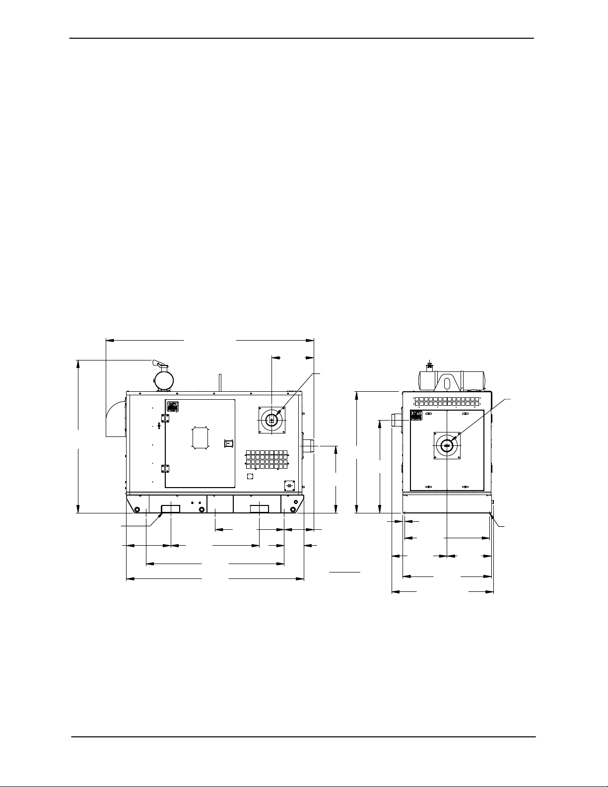
OUTLINE DRAWING
112.58
APPROX
[ 2859,7]
[ 578,7 ]
specific application. Since the pressure supplied
to the pump is critical to performance and safety,
be sure to limit the incoming pressure to 50% of the
maximum permissible operating pressure as
shown on the pump performance curve.
For further assistance, contact your Gorman‐Rupp
distributor or the Gorman‐Rupp Company.
Pump Dimensions
See Figure 1 for the approximate physical dimen
sions of this pump.
22.78
DISCHARGE:
6.00−8 NPT
POWERED BY: ZENITH ZPP857 (NATURAL GAS/LP GAS) ENGINE
SUCTION:
6.00−8
NPT
82.77
[ 2102,5]
APPROX
4.00/[101,6] X 10.00/[254,0]
FORK LIFT POCKET
2 PLACES
24.00
[ 609,6]
48.00
[ 1219,2]
[ 1900,9]
[ 2438,4]
74.84
96.00
37.42
[ 950,5 ]
Figure 1. Pump Model T6A60S-ZPP857-ESP
PREINSTALLATION INSPECTION
The pump assembly was inspected and tested be
fore shipment from the factory. Before installation,
inspect the pump for damage which may have oc
curred during shipment. Check as follows:
65.69
[ 1668,5]
50.26
36.35
[ 923,4]
16.05
[ 407,7 ]
10.59
[ 268,9 ]
DIMENSIONS:
INCHES
[MILLIMETERS]
[ 1276,5]
1.00
[ 25,4 ]
46.00
[ 1168,4]
30.02
[ 762,4 ]
APPROX
55.12
[ 1400,2]
48.00
[ 1219,2]
APPROX
24.00
[ 609,6]
.75/[19,0] DIA
6 HOLES
a. Inspect the pump assembly for cracks, dents,
damaged threads, and other obvious dam
age.
b. Check for and tighten loose attaching hard
ware. Since gaskets tend to shrink after dry
PAGE B - 1INSTALLATION
OM-07174 SUPER T SERIES
ing, check for loose hardware at mating sur
faces.
c. Carefully read all tags, decals, and markings
on the pump assembly, and perform all duties
indicated.
d. Check levels and lubricate as necessary. Re
fer to LUBRICATION in the MAINTENANCE
AND REPAIR section of this manual and per
form duties as instructed.
e. If the pump and
engine have been stored for
more than 12 months, some of the compo
nents or lubricants may have exceeded their
maximum shelf life. These must be inspected
or replaced to ensure maximum pump serv
ice.
If the maximum shelf life has been exceeded, or if
anything appears to be abnormal, contact your
Gorman‐Rupp distributor or the factory to deter
mine the repair or updating policy. Do not put the
pump into service until appropriate action has
been taken.
sion. Connect and tighten the positive cable first,
then the negative cable.
SAFETY AND CONFORMANCE
All aspects of the design and installation of the fuel
supply system must be evaluated in terms of safety
to personnel and equipment, and conformance to
all applicable codes.
Battery Specifications And Installation
Unless otherwise specified on the pump order, the
engine battery was not included with the unit. Re
fer to the following specifications when selecting a
battery.
Table 1. Battery Specifications
Reserve
Capacity
@ 80_ F
(Minutes)
175
Amp/
Hr.
Rating
95
Approx.
Overall
Dims.
(Inches)
13L
x
7W
x
9.5H
Voltage
12 Volts
Cold
Crank
Amps
@ 0_ F
950
Before installing the battery, clean the positive and
negative cable connectors, and the battery termi
nals. Secure the battery by tightening the
holddown brackets. The terminals and clamps
may be coated with petroleum jelly to retard corro
Natural Gas and Liquefied Petroleum
Gas (LPG) presents an extreme explo
sion and fire hazard. Follow all safety
precautions outlined by the National
Fire Protection Association when de
signing and installing the system. Make
certain that the regulators and fuel lines
are of the proper size and capacity for
the system, and that all fuel lines are se
curely connected and free of leaks.
Before installing the system:
1. Check all state and local codes pertaining to
installations of stationary combustion engines
and fuel systems.
2. Consult the following National Fire Protection
Association pamphlet:
NFPA No. 37 - Stationary Combustion
Engines/Gas Turbines
NFPA No. 54 - National Fuel Gas Code Hand
book.
PAGE B - 2 INSTALLATION
SUPER T SERIES OM-07174
NFPA No. 37 - Liquefied Petroleum Gas Stor
age and Handling.
Copies may be ordered from:
National Fire Protection Association
1 Batterymarch Park
Quincy, Massachusets 02269
POSITIONING PUMP
Lifting
Death or serious personal injury and
damage to the pump or components
can occur if proper lifting procedures
are not observed. Make certain that
hoists, chains, slings or cables are in
good working condition and of suffi
cient capacity and that they are posi
tioned so that loads will be balanced
and the pump or components will not be
damaged when lifting. Suction and dis
charge hoses and piping must be re
moved from the pump before lifting. Lift
the pump or component only as high as
necessary and keep personnel away
from suspended objects.
Pump unit weights will vary depending on the
mounting and drive provided. Check the shipping
tag on the unit packaging for the actual weight, and
use lifting equipment with appropriate capacity.
Drain the pump and remove all customer‐installed
equipment such as suction and discharge hoses
or piping before attempting to lift existing, installed
units.
Mounting
To ensure sufficient lubrication to the engine, do
not position the pump and engine more than 15
off horizontal for continuous operation. The pump
and engine may be positioned up to 30_ off hori
zontal for intermittent operation only; however,
the engine manufacturer should be consulted for
continuous operation at angles greater than 15_.
Clearance
When positioning the pump, allow a minimum
clearance of 18 inches (457,2 mm) in front of the
enclosure suction cover to permit removal of the
cover and easy access to the pump.
NATURAL GAS FUEL
The amount of natural gas fuel required for the en
gine is measured in cubic feet per hour. This is cal
culated from the BTU (British Thermal Unit) con
tent of the natural gas supplied, and the horsepow
er required to drive the pump. This unit requires
1,141 CF/hr of natural gas with 1000 BTU con
tent at 10 inches of water column. The BTU con
tent of gas varies in the United States, therefore, it
will be necessary to contact your local gas supplier
to determine the BTU content of the natural gas in
your area.
When burning natural gas having a BTU content of
1000 or over, the engine will deliver the rated horse
power as shown on the pump Specification Data
Sheet. On lower grade natural gas, there will be a
power loss of approximately 3% for each 100 BTU
under 1000.
Natural gas pressures provided by suppliers vary,
so in order to provide the optimal gas supply to the
engine, Gorman‐Rupp has provided a regulator
with the unit that can be adjusted to provide 10
inches of water column of gas pressure to the en
gine. Install the pressure regulator supplied with
the unit in the line supplying the engine, then check
and adjust the fuel pressure as described in CON
NECTING FUEL SUPPLY LINE TO THE UNIT.
_
Locate the pump in an accessible place as close as
practical to the liquid being pumped. Level mount
ing is essential for proper operation.
The pump may have to be supported or shimmed
to provide for level operation or to eliminate vibra
tion.
LPG FUEL
The term Liquefied Petroleum Gas (LPG) refers to
any one of many butane/propane compounds,
some of which have additives for specific applica
tions. Commercial grade propane is recommend
ed.
PAGE B - 3INSTALLATION

OM-07174 SUPER T SERIES
FUEL TANK (LPG ONLY)
The amount of LPG fuel required for the engine is
measured in BTU (British Thermal Unit) per hour.
This unit requires 1,142,038 BTU/hr of LPG fuel
at 10 inches of water column.
The amount of fuel which must be stored at the in
stallation will be determined by the length of time
the engine must operate before refueling is neces
sary. Engine operating time is predicted on system
characteristics such as flow rates, pump capacity,
anticipated number and duration of power failures
in a given time period, programmed engine exer
cise periods, etc.
On LPG fuel systems, fuel consumption is mea
sured in British Thermal Units per Hour (BTU/HR).
This rate of consumption will vary according to en
gine speed and load. For purposes of determining
BTU consumption, assume that all engine operat
ing time will be at full load and at the speed re
quired for rated pumping capacity. (Engine speed
is shown on the performance curve on the Gor
man‐Rupp Specification Data Sheet for the pump).
Short periods of idle speed time need not be con
sidered, as fuel consumption at idle is negligible. If
extended periods of idle speed time are anticipat
ed, calculated fuel consumption should be in
creased accordingly.
Consult the local LPG supplier to determine the
size of fuel tank required. This determination will be
based on the BTU/HR consumption rate, total BTU
storage required, local climate conditions, BTU
content of the fuel to be supplied, and installation
parameters such as local code restrictions and
proposed tank location.
On all units, be sure to specify that the tank will be
used for vapor withdrawal. In this type of system,
fuel is taken from the top of the storage tank in the
vapor state, eliminating the need for a LP gas con
verter, which converts liquid fuel to the vapor re
quired by the engine fuel mixer. The vapor with
drawal system provides an adequate amount of fu
el for an engine the size of which is on the pump
unit. However, if fuel is used at a rate excessive for
the tank size and ambient temperature conditions,
freezing may occur in the tank. This problem can
usually be anticipated by the LPG supplier and
may require selection of a larger tank.
REGULATORS (NATURAL GAS)
The engine is equipped with a natural gas regula
tor designed to supply the engine with natural gas
gas at 6 inches of water column.
Gorman‐Rupp has provided a secondary natural
gas regulator. This regulator has a maximum inlet
pressure of 15 psi (1,0 bar) and an outlet pressure
range of 6 to 14 inches (152 to 356 mm) water col
umn. This regulator can be used to supply the 10
inches (254 mm) the engine requires when the gas
supplier can only supply a pressure greater than
0.5 psi (0,03 bar). The regulator is shipped loose
for field installation and should be located before
any fuel lock‐off valves in the gas supply line.
REGULATORS (LP GAS)
The engine is equipped with an LP gas regulator
designed to supply the engine with LP gas at 6
inches of water column. Gorman‐Rupp provides a
primary regulator and a secondary regulator with
the pump unit.
The pressure in an LPG storage tank with vapor
withdrawal will vary depending on temperature.
For example, the pressure of propane at 70°F
(21°C) is approximately 100 psi (6,9 bar), but this
pressure increases to 180 psi (12,4 bar) at 100°F
(38°C) and decreases to 18 psi (1,2 bar) at 10°F
(-23°C). The primary (first stage) regulator is ca
pable of accepting this wide range of inlet pres
sures while maintaining approximately 10 psi out
let pressure (see the note below) and should be lo
cated on or near the storage tank. The secondary
(second stage) regulator then reduces this 10 psi
(0,6 bar) pressure at its inlet to an outlet pressure of
10 inches of water column (see the note below).
This regulator should be located before any fuel
lock‐off valve in the supply line. If this regulator is
located after a fuel lock‐off valve the operation of
the regulator will be affected by sudden pressure
increase when the lock‐off valve opens. The regu
lators are sized to deliver the fuel flow required by
the engine during full load operation while main
taining pressures within specified limits.
NOTE
The primary regulator output pressure of 10 psi (0,7
bar) is used to illustrate a typical system. Actual
pressure may be higher or lower depending on
code requirements. The primary regulator supplied
PAGE B - 4 INSTALLATION

SUPER T SERIES OM-07174
with the pumping unit has a range of 8 psi to 12 psi
(0,5 to 0,8 bar).
The secondary regulator output pressure of 10
inches of water column is used to illustrate a typical
system. Actual pressure may be higher or lower
depending on code requirements. The secondary
regulator supplied with the pumping unit has a
range of 4 inches to 12 inches (102mm to 305mm)
of water column.
CONNECTING FUEL SUPPLY LINE TO
THE UNIT
There is a 1‐inch pipe connection on the outside of
the enclosure for connecting the incoming gas
supply line. Inside the enclosure, there is a 1‐inch
pipe tee in the engine fuel line. The tee is equipped
with a reducer and a 1/4‐inch pipe plug. Remove
the pipe plug and install a pressure gauge rated in
inches of water column.
Open the fuel supply to the regulator and observe
the pressure gauge. If the reading is less or greater
than 10 inches of water column, remove the cap on
the regulator to expose the adjusting screw plug
beneath it. Turn the adjusting plug clockwise to in
crease the fuel supply or counter‐clockwise to de
crease the fuel supply.
When the supply is properly adjusted to 10 inches
of water column, reinstall the protective cap over
the adjusting screw on the regulator. Remove the
pressure gauge from the fuel line and reinstall the
1/4‐inch pipe plug to avoid vibration damage to the
gauge.
CHANGING FUEL TYPE
If it is necessary to change the type of fuel from nat
ural gas to LP gas or vice‐versa, the fuel line inside
the enclosure to the engine must first be switched
to the correct regulator on the engine for the de
sired fuel. After switching the fuel line, set the tog
gle switch on the engine control to the desired fuel.
This tells the engine control module the fuel has
been changed so the engine can compensate for
the change in fuel supply. After these changes are
complete, check the fuel pressure as described in
CONNECTING FUEL SUPPLY LINE TO THE
UNIT.
SUCTION AND DISCHARGE PIPING
Pump performance is adversely effected by in
creased suction lift, discharge elevation, and fric
tion losses. See the performance curve and notes
on Page E‐1 to be sure your overall application al
lows pump to operate within the safe operation
range.
Materials
Either pipe or hose maybe used for suction and
discharge lines; however, the materials must be
compatible with the liquid being pumped. If hose is
used in suction lines, it must be the rigid‐wall, rein
forced type to prevent collapse under suction. Us
ing piping couplings in suction lines is not recom
mended.
Line Configuration
Keep suction and discharge lines as straight as
possible to minimize friction losses. Make mini
mum use of elbows and fittings, which substantial
ly increase friction loss. If elbows are necessary,
use the long‐radius type to minimize friction loss.
Connections to Pump
Before tightening a connecting flange, align it ex
actly with the pump port. Never pull a pipe line into
place by tightening the flange bolts and/or cou
plings.
Lines near the pump must be independently sup
ported to avoid strain on the pump which could
cause excessive vibration, decreased bearing life,
and increased shaft and seal wear. If hose‐type
lines are used, they should have adequate support
to secure them when filled with liquid and under
pressure.
Gauges
Most pumps are drilled and tapped for installing
discharge pressure and vacuum suction gauges.
If these gauges are desired for pumps that are not
tapped, drill and tap the suction and discharge
lines not less than 18 inches (457,2 mm) from the
suction and discharge ports and install the lines.
Installation closer to the pump may result in erratic
readings.
PAGE B - 5INSTALLATION

OM-07174 SUPER T SERIES
SUCTION LINES
To avoid air pockets which could affect pump prim
ing, the suction line must be as short and direct as
possible. When operation involves a suction lift, the
line must always slope upward to the pump from
the source of the liquid being pumped; if the line
slopes down to the pump at any point along the
suction run, air pockets will be created.
Fittings
Suction lines should be the same size as the pump
inlet. If reducers are used in suction lines, they
should be the eccentric type, and should be in
stalled with the flat part of the reducers uppermost
to avoid creating air pockets. Valves are not nor
mally used in suction lines, but if a valve is used,
install it with the stem horizontal to avoid air pock
ets.
Strainers
ommendations when selecting and applying the
pipe dope. The pipe dope should be compatible
with the liquid being pumped.
Suction Lines In Sumps
If a single suction line is installed in a sump, it
should be positioned away from the wall of the
sump at a distance equal to 1 1/2 times the diame
ter of the suction line.
If there is a liquid flow from an open pipe into the
sump, the flow should be kept away from the suc
tion inlet because the inflow will carry air down into
the sump, and air entering the suction line will re
duce pump efficiency.
If it is necessary to position inflow close to the suc
tion inlet, install a baffle between the inflow and the
suction inlet at a distance 1‐1/2 times the diameter
of the suction pipe. The baffle will allow entrained
air to escape from the liquid before it is drawn into
the suction inlet.
If a strainer is furnished with the pump, be certain
to use it; any spherical solids which pass through a
strainer furnished with the pump will also pass
through the pump itself.
If a strainer is not furnished with the pump, but is
installed by the pump user, make certain that the
total area of the openings in the strainer is at least
three or four times the cross section of the suction
line, and that the openings will not permit passage
of solids larger than the solids handling capability
of the pump.
This pump is designed to handle up to 3‐inch (76,2
mm) diameter spherical solids.
Sealing
Since even a slight leak will affect priming, head,
and capacity, especially when operating with a
high suction lift, all connections in the suction line
should be sealed with pipe dope to ensure an air
tight seal. Follow the sealant manufacturer's rec
If two suction lines are installed in a single sump,
the flow paths may interact, reducing the efficiency
of one or both pumps. To avoid this, position the
suction inlets so that they are separated by a dis
tance equal to at least 3 times the diameter of the
suction pipe.
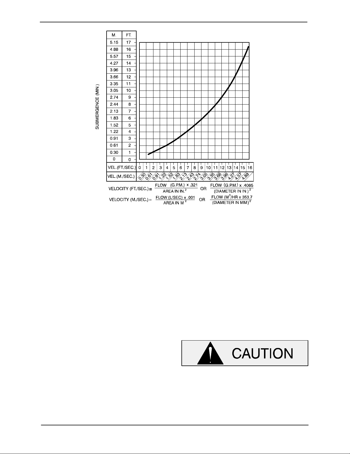
Suction Line Positioning
The depth of submergence of the suction line is
critical to efficient pump operation. Figure 2 shows
recommended minimum submergence vs. veloci
ty.
NOTE
The pipe submergence required may be reduced
by installing a standard pipe increaser fitting at the
end of the suction line. The larger opening size will
reduce the inlet velocity. Calculate the required
submergence using the following formula based
on the increased opening size (area or diameter).
PAGE B - 6 INSTALLATION
SUPER T SERIES OM-07174
Figure 2. Recommended Minimum Suction Line Submergence vs. Velocity
SUBMERSIBLE TRANSDUCER
This unit is equipped with an optional Electronic
Pressure Switch (EPS) that works in conjunction
with a submersible transducer. The submersible
transducer converts pressure to an electrical sig
nal proportional to liquid level. This electrical signal
is distributed to the digital display on the EPS
through a scaling circuit which converts the electri
cal signal to “feet of water”.
When installing the submersible transducer, note
the following:
a. Handle the signal cable and transducer with
care during installation. Carefully lower the
transducer into the wet well or sump; do not
drop it to the bottom. To avoid clogging, sus
pend the transducer off the bottom.
b. Be sure to provide sufficient room in the wet
well or sump so that the transducer does not
get drawn into the suction line. To prevent this,
a flexible suction hose may be extended to lay
along the bottom of the wet well or sump. The
transducer can then be attached to the hose
above the point where it bends along the bot
tom. See Figure 3 for a typical installation.
c. The wet well or sump must be vented to at
mosphere.
d. The EPS is scaled in feet of water column. If
the measured medium is other than 1.0 spe
cific gravity, the reading on the EPS should be
divided by the specific gravity of the mea
sured medium to obtain the actual level.
e. Thoroughly clean the transducer after each
use to prevent clogging.
Do not disassemble the transducer or
loosen the compression nut at the signal
cable entry. This will void warranty. There
are no user‐serviceable parts inside. Do
not nick or cut the jacket of the signal ca
ble; this will cause leakage and void war
ranty.
PAGE B - 7INSTALLATION
 Loading...