

Page 1
TGR 30-150 NG/D
Page 2

2
Page 3
HINWEISE
Das Gerät kann von Kindern ab 8 Jahren und Personen mit
begrenzten physischen, sinnlichen und psychischen
Fähigkeiten oder mit ungenügend Erfahrungen bzw. Kenntnis
benutzt werden, falls sie dabei kontrolliert werden oder über die
sichere Anwendung des Gerätes belehrt worden sind und dass
sie die eventuelle damit verbundene Gefahr verstehen.
Kinder dürfen mit dem Gerät nicht spielen.
Kinder dürfen das Gerät nicht reinigen oder warten, wenn
sie dabei nicht von einer befähigten Person kontrolliert werden.
Die Installation ist nach den gültigen Vorschriften und nach
Anweisungen des Herstellers auszuführen. Die Installation darf
nur ein fachlich ausgebildeter Installateur ausführen.
Bei geschlossenem Druckanschlusssystem ist am
Zuflussrohr des Warmwasserspeichers unbedingt ein
Sicherheitsventil mit Nenndruck von 0,6 MPa (6 bar), 0,9 MPa
(9 bar) oder 1,0 MPa (10 bar) (siehe das Typenschild)
anzuschließen, damit der Nenndruck im Kessel nicht um mehr
als 0,1 MPa (1 bar) übersteigen kann.
Wasser kann aus der Auslassöffnung des Sicherheitsventils
tropfen, d.h. die Auslassöffnung ist auf Atmosphärendruck zu
öffnen.
Der nach unten gerichtete Auslass des Sicherheitsventils
darf in keiner Frostumgebung installiert werden.
Um einen störungsfreien Betrieb zu gewährleisten, ist das
Sicherheitsventil regelmäßig auf Funktion und Leckage zu
überprüfen und bei Bedarf ist der Kalk zu entfernen.
Zwischen dem Warmwasserbereiter und dem
Sicherheitsventil darf kein Absperrventil eingebaut werden, da
sonst die Funktion des Rückschlagventils verhindert ist!
Bevor Sie den Warmwasserbereiter ans Stromnetz
anschließen, ist er unbedingt mit Wasser zu füllen!
Der Warmwasserbereiter ist mit einer zusätzlichen
Thermosicherung versehen. Bei nicht funktionierendem
Arbeitsthermostat kann die Wassertemperatur im
Warmwasserbereiter im Einklang mit den Sicherheitsnormen bis
zu 130 °C steigen. Bei den Wasserleitungsinstallationen sind
DE
3
Page 4
deshalb die eventuell aufkommenden Temperaturüberlastungen
unbedingt zu beachten.
DE
Sollten Sie den Warmwasserbereiter vom Stromnetz
trennen, müssen Sie im bei Frostgefahr das Wasser aus dem
Kessel entleeren.
Bitte versuchen Sie nicht, eventuelle Fehler am Gerät selbst
zu beseitigen, wenden Sie sich lieber an den nächsten
bevollmächtigten Kundendienst.
Unsere Produkte bestehen aus den umgebungs- und
gesundheitsfreundlichen Bauteilen. Die entsprechende Bauweise der
Produkte ermöglicht, dass sie am Ende der Lebensdauer einfach
demontiert und rezykliert werden können.
Durch die Rezyklierung der Materialien werden die Menge der Abfälle und
der Bedarf an der Produktion der Grundstoffe (z.B. Metalle) mit enormem
Energieverbrauch und erheblicher Emission der Schadstoffe vermindert.
Folglich werden auch die natürlichen Ressourcen bewahrt, denn die Abfallteile aus
Kunststoff und Metall können in den verschiedenen Produktionsverfahren wieder
verwendet werden.
Für mehr Informationen über das System der Abfallbeseitigung fragen Sie Ihr
Zentrum zur Entsorgung von Abfällen oder den Verkäufer, bei welchem Sie das
Produkt gekauft haben.
Sehr geehrter Kunde, wir danken Ihnen, dass Sie unser Produkt
erworben haben.
Bitte lesen Sie diese Gebrauchsanweisung aufmerksam durch, bevor
Sie den Warmwasserbereiter installieren und in Betrieb nehmen.
Der Warmwasserbereiter ist im Einklang mit den gültigen Standards hergestellt und
amtlich getestet worden. Ebenso wurde auch das Sicherheitszertifikat und das
Zertifikat EMV (elektromagnetische Verträglichkeit) ausgestellt. Die technischen
Eigenschaften sind auf dem zwischen den Anschlussrohren angebrachten
Typenschild angegeben. Reparaturen und Eingriffe in das Gerät dürfen nur von einer
Fachkraft bzw. dem Kundendienst ausgeführt werden.
INSTALLATION
Der Warmwasserbereiter ist möglichst nahe an Abnahmestellen zu installieren. Bei
der Installation in einem Raum mit Badewanne oder Dusche sind unbedingt die
Anforderungen des Standards IEC 60364-7-701 (VDE 0100, Teil 701) zu beachten.
Er ist mittels Wandschrauben mit Nominaldurchmesser von mindestens 8 mm an der
Wand zu befestigen. Er darf nur in senkrechter Position befestigt werden. Bei
Befestigungswänden mit geringerer Tragfähigkeit, muss vom Installateur eine
geeignete Befestigungsart gewählt werden. Um die Magnesiumanode leichter zu
kontrollieren und zu ersetzen, lassen Sie oben zwischen dem Warmwasserspeicher
4
Page 5
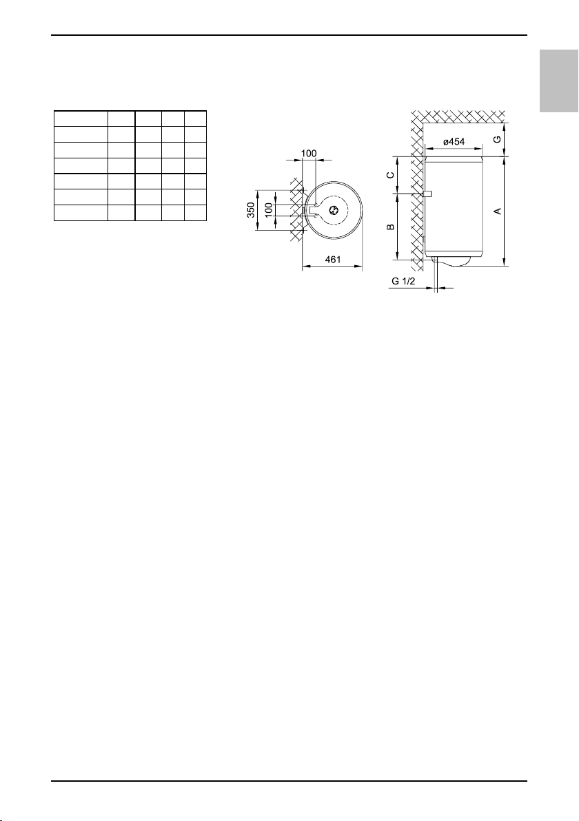
und der Decke genügend Platz (siehe Maß G auf der Skizze der Anschlussmaße).
Wird dies nicht berücksichtigt, muss der Warmwasserspeicher beim beschriebenen
Service von der Wand abmontiert werden.
A B C G
TGR 30 N 468 275 173 80
TGR 50 N 570 365 185 130
TGR 80 N 775 565 190 180
TGR 100 N 935 715 200 260
TGR 120 N 1090 865 205 260
TGR 150 N 1305 1065 220 260
Anschluss- und
Montagedimensionen
des Warmwasserbereiters [mm]
WASSERANSCHLUSS
Die Wasseristallation muss gemäß DIN1988 durchgefürt werden. Die Anschlüsse des
Warmwasserspeichers sind farblich gekennzeichnet, der Kaltwasserzulauf ist blau
und der Warmwasserzulauf ist rot gekennzeichnet.
Der Anschluss des Warmwasserbereiters kann auf zweierlei Arten erfolgen. Das
geschlossene System (druckfestes System) versorgt mehrere Zapfstellen, während
beim offenen System (druckloses System) die Wasserentnahme nur an einer Stelle
erfolgen kann. Je nach ausgewähltem System sind auch entsprechende
Mischbatterien zu installieren.
Bei einem offenen (druckloses) System muss am Warmwasserbereiter ein
Rückschlagventil eingebaut werden, welches das Auslaufen des Wassers aus dem
Kessel verhindert. Wird das im Gerät befindliche Wasser erwärmt, so dehnt sich
dessen Volumen aus. Dies hat zur Folge, dass das Auslaufrohr der Armatur zu
tropfen beginnt. Starkes Festdrehen der Armatur kann bzw. darf dieses Ausdehnen
und Tropfen nicht verhindern, sondern führt möglicherweise zu einer Beschädigung
der Armatur.
Bei einem geschlossenen (druckfesten) System müssen an den Entnahmestellen die
Druckmischbatterien verwendet werden. Am Zulaufstutzen ist wegen der
Funktionssicherheit unbedingt ein Sicherheitsventil oder eine Sicherheitsgruppe
einzubauen, die das Erhöhen des Drucks im Kessel um mehr als 0,1 MPa (1 bar)
über den Nominalwert verhindert. Die Auslassdüse am Sicherheitsventil muss
unbedingt über einen Auslass für den Luftdruck verfügen.
Bei der Aufheizung des Wassers wird der Druck im Kessel erhöht bis er den am
Sicherheitsventil eingestellten Wert erreicht. Da die Rückleitung des Wassers zurück
in die Wasserleitung verhindert ist, kann es zum Abtropfen des Wassers aus der
Auslassöffnung des Sicherheitsventils kommen. Das abtropfende Wasser kann durch
den Auffangansatz, den Sie unter dem Sicherheitsventil anbringen, in den Ablauf
abgeleitet werden. Das Ablaufrohr unter dem Auslass des Sicherheitsventils muss in
der Richtung gerade nach unten und in einer frostfreien Umgebung angebracht
werden.
Falls die bereits ausgeführte Installation keine Möglichkeit bietet, das tropfende
DE
5
Page 6

1 7 53546328
Wasser aus dem Sicherheitsventil in den Abfluss zu leiten, kann das Tröpfeln auch
durch das 3 l- Expansionsgefäß verhindert werden. Das Gefäß montieren Sie am
DE
Zulaufrohr des Warmwasserbereiters.
Das richtige Funktionieren des Sicherheitsventils müssen Sie in regelmässigen
Zeitabständen selber überprüfen und nach Bedarf den Kalk entfernen und die
eventuelle Blockade des Ventils beseitigen. Bei einer Prüfung ist durch Verschiebung
des Hebels oder durch Lösen der Ventilmutter (je nach Ventiltyp) der Auslauf aus
dem Sicherheitsventil zu öffnen. Dabei muss aus der Auslaufdüse des Ventils das
Wasser ausfließen, was die einwandfreie Funktion des Ventils bestätigt.
Legende:
1 - Sicherheitsventil
2 - Ablaufrohr
3 - Rückflussstopp
4 - Druckminderer
5 - Absperrventil
Es darf kein Absperrventil zwischen dem Warmwasserbereiter und
Sicherheitsventil installiert sein, da sonst die Funktion des Sicherheitsventils
verhindert wird.
Der Warmwasserbereiter kann an die Haushaltswasserleitung ohne Reduzierventil
angeschlossen werden, wenn der Druck in der Leitung niedriger als der Nenndruck
ist. Sollte der Druck in der Leitung den Nenndruck überschreiten, so müssen Sie das
Reduzierventil unbedingt einbauen.
Bevor Sie das Gerät an das Stromnetz anschließen, ist es unbedingt mit Wasser zu
füllen. Bei erster Befüllung ist der Warmwasserhebel an der Mischbatterie zu öffnen.
Der Warmwasserbereiter ist voll, wenn das Wasser durch das Ausflussrohr der
Mischbatterie ausfliest.
6 - Prüfstutzen
7 - Ablaufsiphon
8 - Expansionsgefäß
H - Kaltwasser
T - Warmwasser
ELEKTRISCHER ANSCHLUSS
Vor dem Anschluss an das Stromnetz muss ein angemessenes
Anschlusskabel von minimalem Durchschnitt von 1,5 mm2
(H05VV-F 3G 1,5 mm2) eingebaut werden. Dazu ist der
Schutzdeckel abzuschrauben.
Der Anschluss des Warmwasserbereiters an das Stromnetz hat
in Übereinstimmung mit den gültigen Normen zu erfolgen. Dem
Gerät muss eine allpolige Trennvorrichtung vorgeschaltet
6
Page 7

230 V~
LN
3
2
werden, der sämtliche Speisepole laut nationalen Installationsvorschriften unterbricht.
Legende:
1 - Anschlussklemme
2 - Thermostat mit zweipolige
Thermosicherung
3 - Heizkörper
4 - Kontrolleuchte
L - Phasenleiter
N - Neutralleiter
- Schutzleiter
Elektroschaltbild
HINWEIS: Vor jedem Eingriff ist der Warmwasserspeicher spannungsfrei zu
schalten!
GEBRAUCH UND WARTUNG
Nach dem Anschluss an die Wasserleitung und das Stromnetz ist der
Warmwasserbereiter zum Gebrauch bereit. Durch Drehen des
Thermostatdrehknopfes an der unteren Seite des Schutzdeckels können Sie die
gewünschte Wassertemperatur zwischen 10 °C und 65 °C +5 °C/-0 °C wählen. Wir
empfehlen den Drehknopf auf die "eco" Position zu stellen. Das ist die sparsamste
Einstellung; die Wassertemperatur ist etwa 55 °C, die Kalkablagerung und der
Wärmeverlust sind geringer als bei höherer Temperatur. Im Betriebszustand, ist ein
Geräusch im elektrischen Heizkörper hörbar. Die Funktion des elektrischen
Heizkörpers wird durch die Kontrolleuchte gezeigt. An der Stirnseite des Heizkörpers
ist das Bimetall-Thermometer angebracht und die Zeiger bewegen sich im
Uhrzeigersinn, wenn das warme Wasser im Heizkörper ist. Der Thermometer zeigt
die Temperatur am Aufstellort an, durch das Drehen des Thermostatknopfes stellen
Sie aber die Wassertemperatur im unteren Teil des Warmwasserbereiters ein. Die
Folge kann die Temperaturdifferenz zwischen den beiden Anzeigewerten sein. Wenn
Heizkörper längere Zeit nicht aktiv ist, verhindern Sie das Einfrieren dessen Inhalts
so, dass Sie den Thermostatdrehknopf auf die Position " " stellen, der Heizkörper
bleibt aber angeschlossen. In dieser Einstellung hält das Gerät bei minimalem
Energieverbrauch das Wasser auf einer Temperatur von etwa 10 °C. Sollten Sie den
Heizkörper ausschalten, müssen Sie bei Frostgefahr das Wasser auslassen. Danach
kann an einer der angeschlossenen Armaturen das Warmwasserventil geöffnet
werden. Das Wasser wird über den Kaltwassereinlauf oder über das Sicherheitsventil
abgelassen, so dass der Hebel oder die Kappe des Sicherheitsventils wie bei der
Kontrolle auf seine einwandfreie Funktion gedreht wird. Es ist sinnvoll bei der
Montage einen speziellen Reduziernippel (T-Stück) oder ein Auslassventil zwischen
dem Sicherheitsventil und dem Zuflussrohr zu installieren.
Das verbleibende Restwasser im Gerät kann durch Abdrehen des Heizflansches
abgelassen werden.
Die Oberflächen des Warmwasserspeichers können durch Abwischen mit einem
feuchten Lappen und mit einer milden Waschmittellösung gereinigt werden.
Verwenden Sie keine Lösungsmittel oder grobe Reinigungsmittel.
DE
7
Page 8

Ein regelmäßiger Service gewährleistet eine einwandfreie Funktion und lange
Lebensdauer des Warmwasserspeichers.
DE
In regelmäßigen Abständen, nicht länger als 36 Monate, ist die korrekte Funktion der
Schutzanode durch einen beauftragten Fachmann zu prüfen, um die Garantie gegen
Durchrostung des Kessels geltend machen zu können. Kalkrückstände sind zu
entfernen. Die Schutzanode kann mit geringem Aufwand durch Messen des
Anodenstromes geprüft werden.
Bei der Erwärmung des Wassers sind Kalkablagerungen im Speicher nicht ganz zu
vermeiden. Diese können durch den Kundendienst entfernt werden. Die Kalkmenge
im Inneren des Warmwasserspeichers hängt von der Wasserqualität und der
eingestellten Warmwassertemperatur ab.
Der Kundendienst wird Ihnen nach der Überprüfung des Warmwasserspeichers auf
Grund des festgestellten Zustands das Datum der nächsten Kontrolle empfehlen.
Bitte, versuchen Sie nicht, eventuelle Fehler am Gerät selbst zu beseitigen,
wenden Sie sich lieber an den nächsten bevollmächtigten Kundendienst.
TECHNISCHE CHARAKTERISTIKEN
Typ
Angegebenes Lastprofil
Energieeffizienzklasse
Warmwasserbereitungs-
Energieeffizienz (ƞwh) 1)
Jährlicher Stromverbrauch 1) [kWh]
Täglicher Stromverbrauch 2) [kWh]
Temperatureinstellung des
Thermostats
Wert "smart"
Volumen [l]
Mischwassermenge bei 40 °С V40 2) [l]
Aufwärmezeit von 10 °С bis 65 °С [h] 0:59 1:38 2:37 3:16 3:55 4:54
Nenndruck
Gewicht / voll [kg]
Korrosionsschutz des Kessels emailliert / Mg-Schutzanode
Leistung des elektrischen
Heizkörpers
Anschlussspannung [V~] 230
Schutzklasse I
Schutzart (Schutzstufe) IP23
1) Verordnung der Kommission EU 812/2013; EN 50440
2) EN 50440
1)
WIR BEHALTEN UNS DAS RECHT FÜR ÄNDERUNGEN VOR, DIE DIE
FUNKTIONALITÄT DES GERÄTES NICHT BEEINTRÄCHTIGEN.
Die Gebrauchsanweisungen finden Sie auch auf unseren Webseiten
http://www.gorenje.com.
TGR 30 N TGR 50 N TGR 80 N TGR 100 N TGR 120 N TGR 150 N
S M M L L XL
C C C C C D
[%]
33,1 36,0 36,0 37,1 37,0 37,0
558 1427 1428 2762 2770 4531
2,671 6,692 6,698 12,850 12,901 21,098
"eco" "eco" "eco" "eco" "eco" "eco"
0 0 0 0 0 0
30,4 47,5 76,1 96,1 116,4 146,1
- 67 92 131 148 212
[MPa
(bar)]
15,5/45,5
[W] 2000
21/71 27/107 31/131 35/155 41/191
0,6 (6)
8
Page 9

WARNINGS
The appliance may be used by children older than 8 years
old, elderly persons and persons with physical, sensory or
mental disabilities or lacking experience and knowledge, if they
are under supervision or taught about safe use of the appliance
and if they are aware of the potential dangers.
Children should not play with the appliance.
Children should not clean or perform maintenance on the
appliance without supervision.
Installation should be carried out in accordance with the
valid regulations and according to the instructions of the
manufacturer and by qualified staff.
In a closed, pressurised system of installation, it is obligatory
to install a safety valve on the inlet pipe with a rated pressure of
0.6 MPa (6 bar), 0.9 MPa (9 bar) or 1.0 MPa (10 bar) (see the
label), which prevents the elevation of pressure in the boiler by
more than 0.1 MPa (1 bar) above the rated pressure.
Water may drip from the outlet opening of the safety valve,
so the outlet opening should be set to atmospheric pressure.
The outlet of the safety valve should be installed facing
downwards and in a non-freezing area.
To ensure proper functioning of the safety valve, the user
should perform regular controls to remove limescale and make
sure the safety valve is not blocked.
Do not install a stop valve between the water heater and the
safety valve, because it will impair the pressure protection of the
heater!
Before connecting it to the power supply, the water heater
must be filled with water!
The heater is equipped with an additional thermal cut-off for
protection in case of failure of the operating thermostat. In this
case, however, the temperature of the water in the heater can
reach up to 130 °C according to the safety standards. During
the water supply installation, the possibility of temperature
overloads should be taken into account.
If the heater is to be disconnected from the power supply,
please drain any water from the heater to prevent freezing.
EN
9
Page 10

Please do not try to fix any defects of the water heater on
your own. Call the nearest authorised service provider.
EN
Our products incorporate components that are both environmentally safe
and harmless to health, so they can be disassembled as easily as possible
and recycled once they reach their final life stage.
Recycling of materials reduces the quantity of waste and the need for
production of raw materials (e.g. metals) which requires a substantial
amount of energy and causes release of harmful substances. Recycling procedures
reduce the consumption of natural resources, as the waste parts made of plastic and
metal can be returned to various production processes.
For more information on waste disposal, please visit your waste collection centre or
the store where the product was purchased.
Dear buyer, thank you for purchasing our product.
Prior to the installation and first use of the electric water
heater, please read these instructions carefully.
This water heater has been manufactured in compliance with the relevant standards
and tested by the relevant authorities as indicated by the Safety Certificate and the
Electromagnetic Compatibility Certificate. The technical characteristics of the product
are listed on the label affixed between the inlet and outlet pipes. The installation must
be carried out by qualified staff. All repairs and maintenance work within the water
heater, e.g. lime removal or inspection/replacement of the protective anticorrosion
anode, must be carried out by an authorised maintenance service provider.
INSTALLATION
The water heater shall be installed as close as possible to the outlets. When installing
the water heater in a room with a bathtub or shower, take into account the
requirements defined in IEC Standard 60364-7-701 (VDE 0100, Part 701). It has to
be fitted to the wall using appropriate wall screws with a minimum diameter of 8 mm.
A wall with a poor load-bearing capacity must be properly reinforced where the heater
will be installed. The water heater may only be fixed upon the wall vertically. We
recommend the distance between the water heater and the ceiling is large enough to
allow simple replacement of the Mg anode (see dimension G in the Installation
Drawing), in order to avoid unnecessary dismounting of the heater during the
servicing intervention.
10
Page 11

A B C G
TGR 30 N 468 275 173 80
TGR 50 N 570 365 185 130
TGR 80 N 775 565 190 180
TGR 100 N 935 715 200 260
TGR 120 N 1090 865 205 260
TGR 150 N 1305 1065 220 260
Connection and installation
dimensions of the water heater
[mm]
CONNECTION TO THE WATER SUPPLY
The water heater connections for the inlet and outlet of water are colour-coded. The
inlet of cold water is marked with blue colour, while the hot water outlet is marked
with red colour.
The water heater can be connected to the water supply in two ways. The closedcircuit pressure system enables several points of use, while the open-circuit gravity
system enables a single point of use only. The mixer taps must also be installed in
accordance with the selected installation mode.
The open-circuit gravity system requires the installation of a non-return valve in order
to prevent the water from draining out of the tank in the event of the water supply
running dry or being shut down. This installation mode requires the use of a crossflow mixer tap. As the heating of water expands its volume, this causes the tap to
drip. The dripping cannot be stopped by tightening it further; on the contrary, the
tightening can only damage the tap.
The closed-circuit pressure system requires the use of pressure mixer taps. For
safety reasons the supply pipe must be fitted with a safety valve or alternatively, a
valve of the safety class that prevents the pressure in the tank from exceeding the
nominal pressure by more than 0.1 MPa (1 bar). The outlet opening on the relief
valve must be equipped with an outlet for atmospheric pressure.
The heating of water in the heater causes the pressure in the tank to increase to the
level set by the safety valve. As the water cannot return to the water supply system,
this can result in dripping from the outlet of the safety valve. The drip can be piped to
the drain by installing a catching unit just below the safety valve. The drain installed
below the safety valve outlet must be piped down vertically and placed in an
environment that is free from the onset of freezing conditions.
In case the existing plumbing does not enable you to pipe the dripping water from the
safety valve into the drain, you can avoid the dripping by installing a 3-litre expansion
tank on the inlet water pipe of the boiler.
In order to provide correct operation of the safety valve, periodical inspections of the
relief valve must be carried out by the user to eliminate any limescale and check if the
safety valve is blocked. To check the valve, open the outlet of the safety valve by
EN
11
Page 12

1 7 53546328
turning the handle or unscrewing the nut of the valve (depending on the type of the
valve). The valve is operating properly if the water comes out of the nozzle when the
EN
outlet is open.
Closed (pressure) system Open (non-pressure) system
Legend:
1 - Safety valve
2 - Test valve
3 - Non-return valve
4 - Pressure reduction valve
5 - Closing valve
Between the water heater and safety valve, no closing valve may be built in
because it could impede the function of the safety valve.
The heater can be connected to the domestic water supply network without a
pressure-reducing valve if the pressure in the network is lower than the nominal
pressure. If the pressure in the network exceeds the nominal pressure, a pressurereducing valve must be installed.
Before connecting it to the power supply, the water heater must be filled with
water. When filling the heater for the first time, the tap for the hot water on the
mixing tap must be opened. When the heater is filled with water, the water starts to
run through the outlet pipe of the mixing tap.
6 - Checking fitting
7 - Funnel with outlet connection
8 - Expansion tank
H - Cold water
T - Hot water
CONNECTING THE WATER HEATER TO
THE POWER SUPPLY NETWORK
disconnect switch must be installed between the water heater and the power supply
network.
Before connecting to the power supply network, install a power
supply cord in the water heater, with a min. diameter of 1.5 mm2
(H05VV-F 3G 1.5 mm2). To do this, the protective plate must be
removed from the water heater.
Connecting the heater to the power supply network must take
place in accordance with the standards for electric appliances.
To comply with the national installation regulations, an all poles
12
Page 13

230 V~
LN
3
2
Legend:
1 - Connection terminal
2 - Thermostat and
bipolar thermal cut-out
3 - Electric heating element
4 - Pilot lamp
L - Live conductor
N - Neutral conductor
- Earthing conductor
Electric installation
CAUTION: Before any intervention into the interior of the water heater,
disconnect it from the power supply network!
OPERATION AND MAINTENANCE
After connecting to the water and power supply, the heater is ready for use. By
turning the thermostat knob, water temperature can be set between 10 °C and 65 °C
+5 °C/-0 °C. We recommend that the knob be set to the position "eco" ensuring the
most economic operation of the water heater. This way, the water temperature is
maintained at 55 °C while the operation also results in less lime sediment as well as
in less heat losses than is the case at higher temperatures. During the operation of
an electric heater can hear noise in the water heater. The light indicator shows the
operation of the heating element. On the casing of the water heater a bimetal
thermometer is mounted, pointing clockwise (to the right) whenever there is hot water
in the water heater. The thermometer shows the temperature at the place of
installation, while the control knob on the thermostat sets the temperature of water in
the bottom part of the heater. As a result these two temperatures may differ. When
the water heater is not in use for longer periods of time, it should be protected from
freezing by setting the temperature to " ". Do not disconnect the power. Thus the
temperature of water is maintained at about 10 °C. Should you choose to disconnect
the power, the water heater should be thoroughly drained before the onset of freezing
conditions. Water from the heater is drained through the inlet pipe of the heater. For
this purpose, a special fitting (T-fitting) must be mounted between the relief valve and
the heater inlet pipe, or a discharge tap. The heater can be discharged directly
through the relief valve, by rotating the handle or the rotating valve cap to the same
position as for checking the operation. Before discharge, make sure the heater is
disconnected from the power supply, and open the hot water on the connected mixer
tap. After discharging through the inlet pipe, there is still some water left in the water
heater. The remaining water will be discharged after removing the heating flange,
through the heating flange opening.
The external parts of the water heater can be cleaned with a mild detergent solution.
Do not use solvents and abrasives.
Regular preventive maintenance inspections ensure faultless performance and long
life of your heater. The first of these inspections should be carried out by the
authorised maintenance service provider about three years from installation in order
EN
13
Page 14

to inspect the wear of the protective anticorrosion anode and remove the lime coating
and sediment as required. The lime coating and sediment on the walls of the tank
EN
and on the heating element is a result of quality, quantity and temperature of water
flowing through the water heater. The maintenance service provider shall also issue a
condition report and recommend the approximate date of the next inspection.
Never try to repair any possible faults of the water heater by yourself, but
inform about it the nearest authorised service workshop.
TECHNICAL PROPERTIES OF THE
APPLIANCE
Type
Declared load profile
Energy efficiency class
Water heating energy efficiency
(ƞwh) 1)
Annual electricity consumption 1) [kWh]
Daily electricity consumption 2) [kW h]
Thermostat temperature settings "eco" "eco" "eco" "eco" "eco" "eco"
Value of "smart"
Volume [l]
Quantity of mixed water at 40 °С
V40 2)
Heating time from 10 °С to 65 °С [h] 0:59 1:38 2:37 3:16 3:55 4:54
Rated pressure
Weight / Filled with water [kg]
Anti-corrosion of tank enamelled & Mg Anode
Power of electrical heater [W] 2000
Connection voltage [V~] 230
Protection class I
Degree of protection IP23
1) EU Regulation 812/2013; EN 50440
2) EN 50440
1)
WE RESERVE THE RIGHT TO MAKE CHANGES THAT DO NOT IMPAIR THE
FUNCTIONALITY OF THE DEVICE.
The user manual can also be found at our website http://www.gorenje.com .
TGR 30 N TGR 50 N TGR 80 N TGR 100 N TGR 120 N TGR 150 N
S M M L L XL
C C C C C D
[%]
33,1 36,0 36,0 37,1 37,0 37,0
558 1427 1428 2762 2770 4531
2,671 6,692 6,698 12,850 12,901 21,098
0 0 0 0 0 0
30,4 47,5 76,1 96,1 116,4 146,1
[l]
- 67 92 131 148 212
[MPa
(bar)]
15,5/45,5
21/71 27/107 31/131 35/155 41/191
0,6 (6)
14
Page 15

15
Page 16

10/2016
489340
 Loading...