

Page 1
- 2-1 -
TAPE DECK ADJUSTMENT
1. AZIMUTH ADJUSTMENT
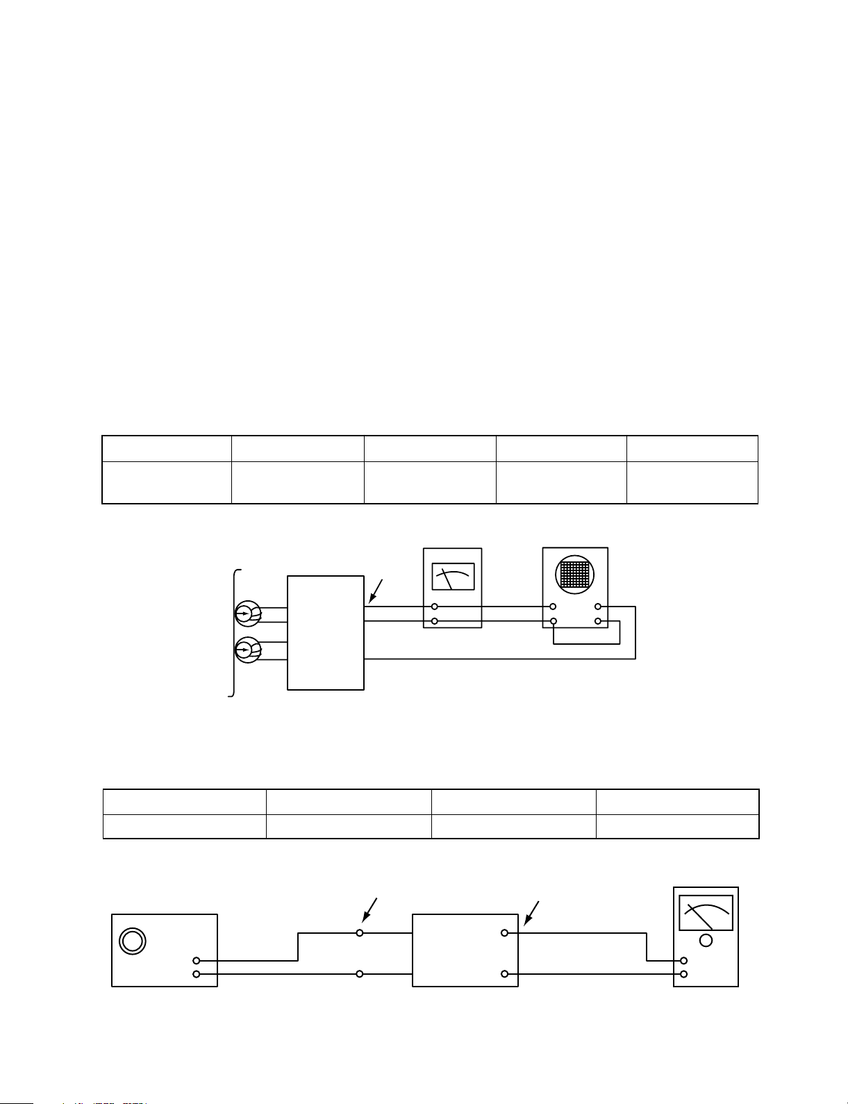
Figure 1. Azimuth Adjustment Connection Diagram
CH1 CH2
Speaker Out
Playback Mode
Head
Test Tape
MTT-114
L ch
R ch
GND
Dual-trace
synchroscope
Electronic
Voltmeter
L out
R out
Unit
SECTION 2. ELECTRICAL
ADJUSTMENTS
This set has been aligned at the factory and normally will not require further adjustment. As a result, it is not
recommended that any attempt is made to modificate any circuit. If any parts are replaced or if anyone tampers
with the adjustment, realignment may be necessary.
IMPORTANT
1. Check Power-source voltage.
2. Set the function switch to band being aligned.
3. Turn volume control to minimum unless otherwise noted.
4. Connect low side of signal source and output indicator to chassis ground unless otherwise specified.
5. Keep the signal input as low as possible to avoid AGC and AC action.
Deck Mode Test Tape Test Point Adjustment Adjust for
Palyback MTT-114 Speaker Out
DECK Screw
Maximum
Azimuth Screw
2. TUNER ADJUSTMENT
Figure 2. Tuner(S curve) Adjustment Connection Diagram
Unit
Signal Generator
GND
Electronic
OSCILLOSCOPE
FM Antenna
Terminal
Speaker
Item Test Point Adjustment Adjust for
DC Voltage Check Point TP1, TP2 L101 0V±50mV
(FM)
 Loading...