

Page 1
RT700i SERIES BARCODE PRINTER
RT700iW SERIES BARCODE PRINTER
USER MANUAL
User Manual
Version
Issue Date
P/N
: RT700i(W) series
: Rev.E.2
: 2020.03.16
: 920-014811-01
Page 2

RT700i SERIES USER MANUAL
4
for Ethernet
41
5
Accessories
049
6
Maintenance and Adjustment
061
Appendix
File Manipulation When Using USB Stick
CONTENTS
1 Barcode Printer 001
1.1
1.2
2 Printer Setup 006
2.1
2.2
2.3
2.4
2.5
3 Printer Setting and Control 021
3.1
3.2
3.3
3.4
3.5
3.6
3.7
3.8 USB Host
3.9 Dump Mode Begin 039
Box Content
Getting to Know Your Printer
Open the Printer
Loading the Ribbon
Loading the Label Roll Module
Connecting the Printer to the Host Computer
Installing Printer Driver and QLabel with Super
Wizard CD
Operation Panel
LCD Interface Introduction
LAN Setting
LCD Password
LCD Interface Function
Label Calibration and Self Test
Error Alerts
001
002
006
007
012
014
016
021
022
026
028
030
034
036
038
NetSetting
4.1
4.2
5.1
5.2
5.3
6.1
6.2
Product Specifications
Installing the NetSetting Software
The Interface of NetSetting
Preparation Steps
Installing the Label Dispenser
Installing the Cutter
Cleaning the Print Head
Troubleshooting
Interface
Bluetooth Module
WiFi Printer Server Module Installation - For RT700iW/ RT730iW
0
041
042
049
051
057
061
062
Contents
Page 3

RT700i SERIES USER MANUAL
FCC COMPLIANCE STATEMENT
FOR AMERICAN USERS
This equipment has been tested and found to comply with the limits for a CLASS A digital device,
pursuant to Part 15 Subpart B of the FCC Rules. These limits are designed to provide reasonable
protection against harmful interference when the equipment is operated in a commercial
environment. This equipment generates, uses, and can radiate radio frequency energy and, if not
installed and used in accordance with the instructions, may cause harmful interference to radio
communications.Operation of this equipment in a residential area is likely to cause harmful
interference in which case the user will be required to correct the interference at own expense.
EMS AND EMI COMPLIANCE STATEMENT
FOR EUROPEAN USERS
This equipment has been tested and passed with the requirements relating to electromagnetic
compatibility based on the standards EN55032:2012/AC 2013 Class A, EN61000-3-2:2014 EN
61000-3-3:2013 and EN55024:2010, IEC 61000-4-2:2008 series The equipment also tested and passed
in accordance with the European Standard EN55032 for the both Radiated and Conducted
emissions limits.
RT700i SERIES
TO WHICH THIS DECLARATION RELATES
IS IN CONFORMITY WITH THE FOLLOWING STANDARDS
IEC 60950-1:2005(2nd Edition)+Am 1:2009 Am2:2013, CB9254-2008 (Class A ) ; GB17625. 1-2012;
GB4943.1-2011, EN55032:2012/AC 2013 Class A EN61000-3-3:2013, EN 61000-3-3:2013 and
EN55024:2010, IEC 61000-4-2:2008 series, UL 60950-1 & CAN/CSA C22.2 No. 60950-1-07, Information
Technology Equipment - Safety - Part 1: General Requirements, CFR 47, Part 15 Subpart B
WARNING
This is a Class A product. In a domestic environment this product may cause radio interference
in which case the user may be required to take adequate measures.
此为Class A产品,在生活环境中,该产品可能造成无线电干扰,在这种情况下,可能需要用户对其干扰采取切实可行
的措施。
이 기기는 업무용으로 전자파적합등록을 한 기기이오니 판매자또는 사용자는 이점을 주의하시기 바라며, 만약 잘못 판매 또는
구입하였을 때에는 가정용으로 교환하시기 바랍니다
.
Declaration
Page 4

RT700i SERIES USER MANUAL
SAFETY INSTRUCTIONS
Please read the following instructions carefully.
1. Keep the equipment away from humidity.
2. Before you connect the equipment to the power outlet, please
check the voltage of the power source.
3. Make sure the printer is off before plugging the power connector
into the power jack.
4. It is recommended that you connect the printer to a surge
protector to prevent possible transient overvoltage damage.
5. Be careful not to get liquid on the equipment to avoid electrical
shock.
6. For safety and warranty reasons, ONLY qualified service personnel
should open the equipment.
7. Do not repair or adjust energized equipment under any
circumstances.
Caution
**** Danger of explosion if battery is incorrectly replaced. Replace only with the equivalent type recommended by
the manufacturer.
**** Dispose of used batteries according to the manufacturer’s instructions.
**** Only use with designated power supply adapter model.
**** Changes or modifications not expressly approved by the party responsible for compliance could void the user's
authority to operate the equipment.
Specifications are subject to change without notice.
Safety instructions
Page 5
1 Barcode Printer
1.1 Box Content
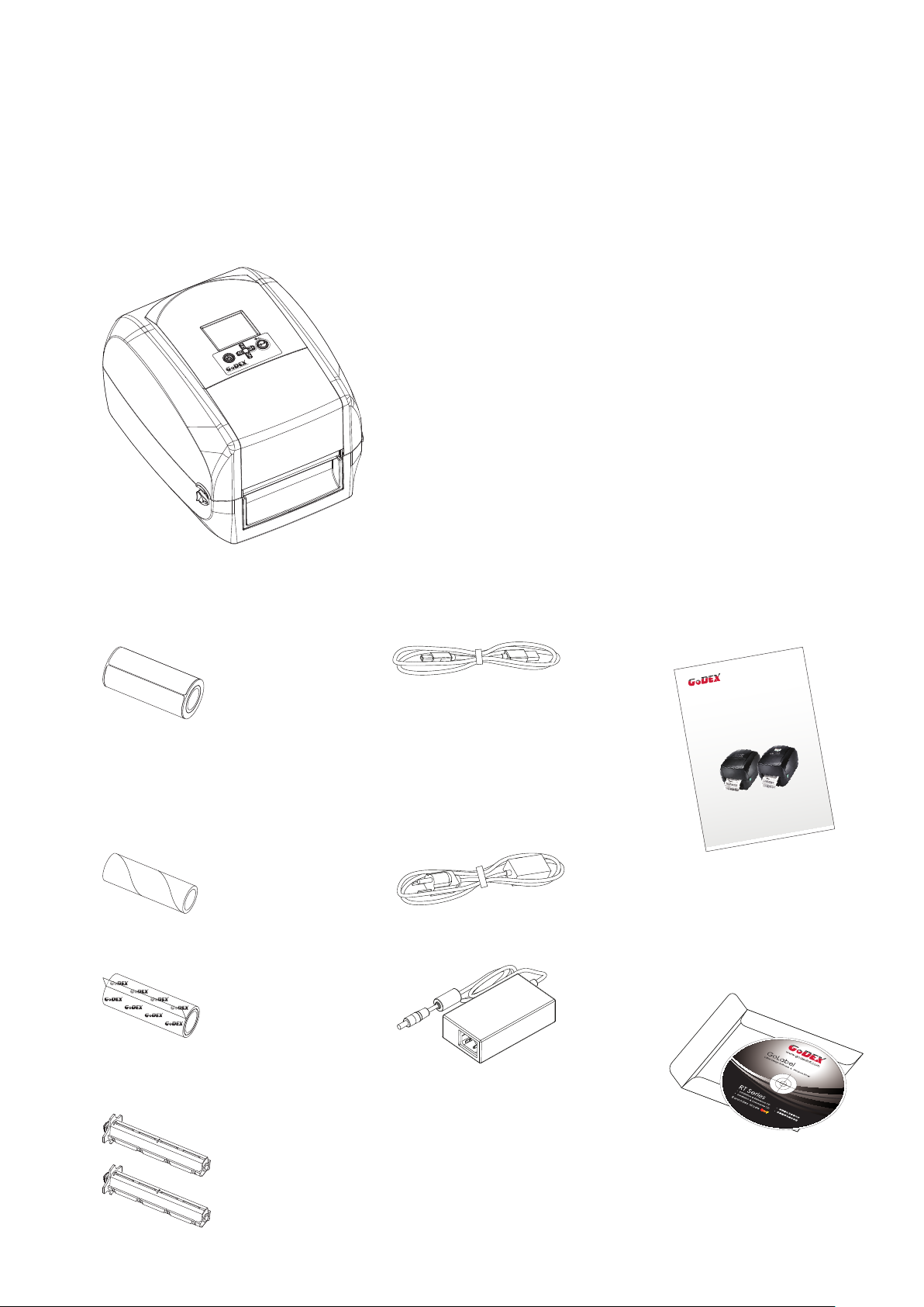
Please check that all of the following items are included with your printer.
RT700i Series Barcode Printer
RT700i
Label Stock
Ribbon Module
Empty Ribbon Core
Ribbon
USB Cable
Power Adapter
Power Cord
AC Adapter
RT700i Series Quick Guide
RT700/RT700i/RT700
CD
Including GoLabel software
and RT700i/RT730i user manual.
x
Series
Ribbon Hubs
Set of 2.
1
Page 6
1 Barcode Printer
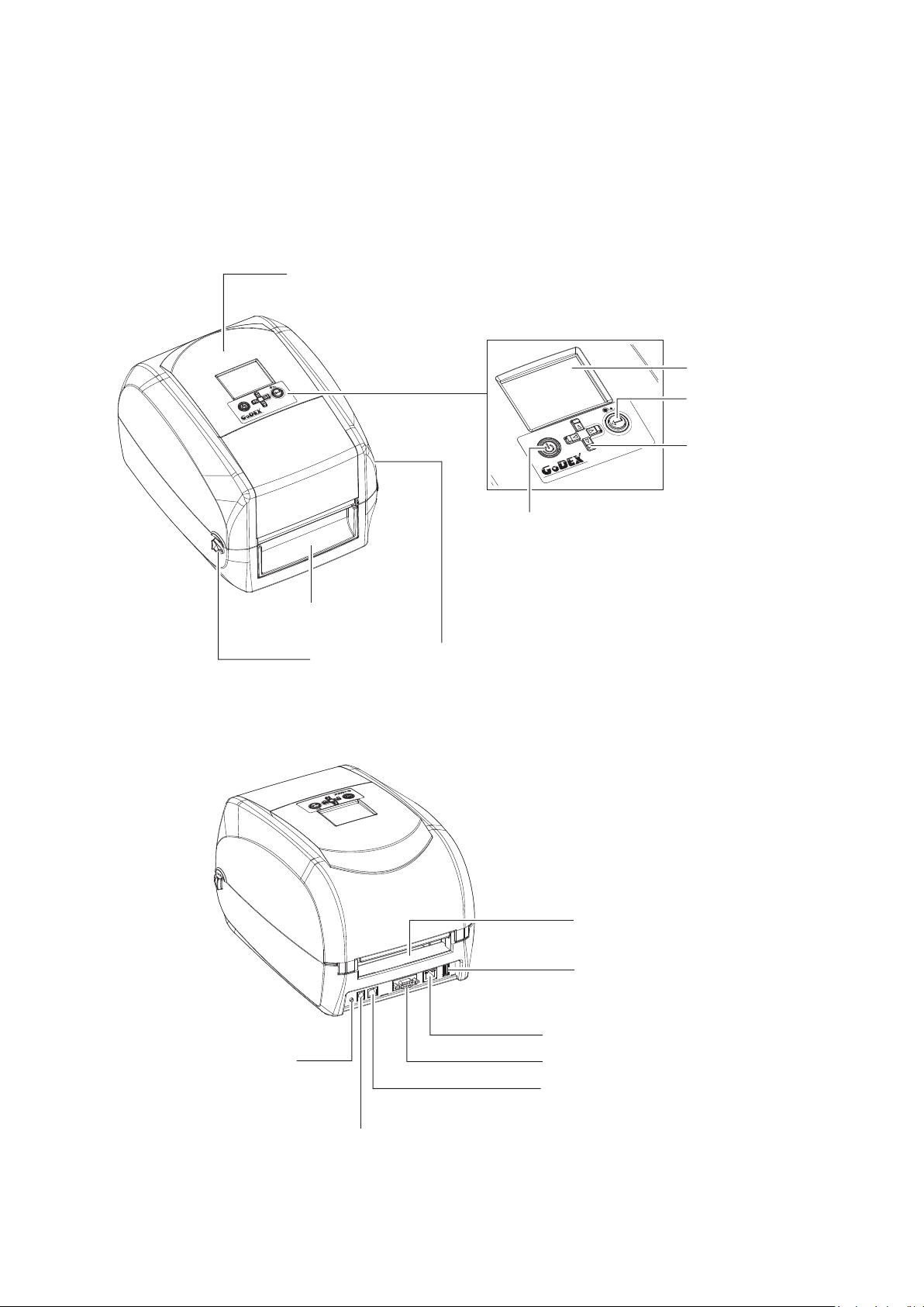
1.2 Getting to Know Your Printer
Device Overview
Front View
PRINTER COVER
OPERATION PANEL
LCD SCREEN
FEED BUTTON
RT700i
DIRECTION KEY
RT700i
POWER BUTTON
FRONT COVER
COVER RELEASE CATCHES
Pull catches for opening the printer cover
Rear View
RT700i
CALIBRATION BUTTON
FAN-FOLD LABEL INSERT
Feed slot for continuous labels
USB HOST
ETHERNET PORT
SERIAL PORT
USB PORT
POWER JACK
2
Page 7
1 Barcode Printer
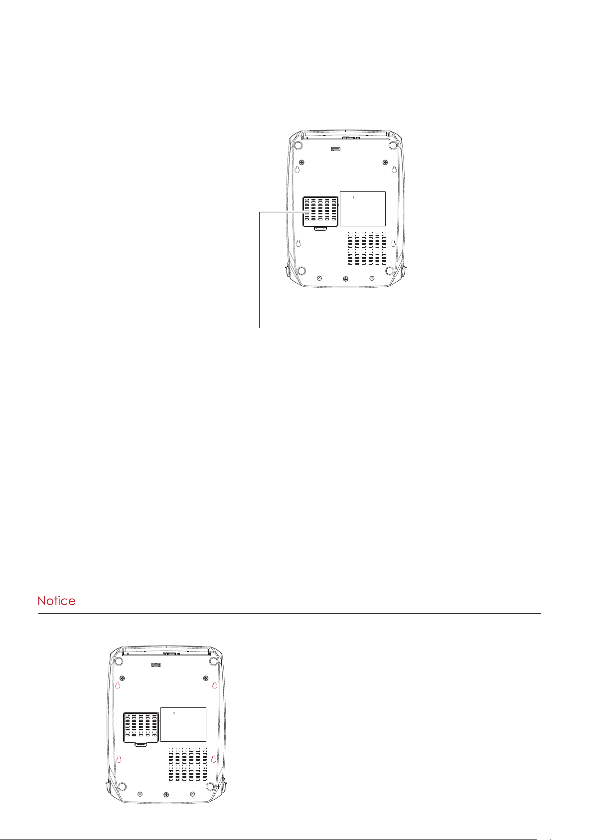
Bottom View
COVER OF THE MODULE CONNECTION JACKS
**** Cut-outs are not intended for wall-mount use.
3
Page 8
1 Barcode Printer
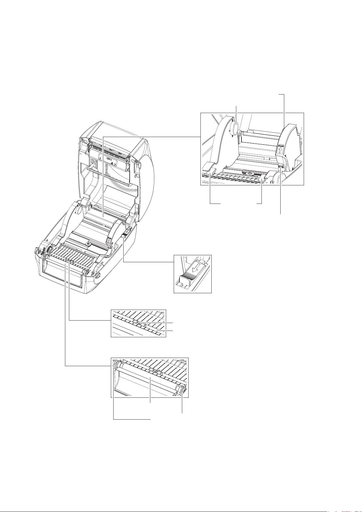
The Internal View of Printer
LABEL
SUPPLY
MODULE
RELEASE CATCH
Release catch for closing
the printer cover
LABEL SUPPLY HUB
Set of 2
LABEL GUIDE
Set of 2
RELEASE CATCH
Release catch for opening
the label supply hub
LABEL SENSOR
MODULE
PLATEN MODULE
PLATEN
LABEL SENSOR
GUIDE TRACK
PLATEN LOCKERS
4
Page 9
1 Barcode Printer
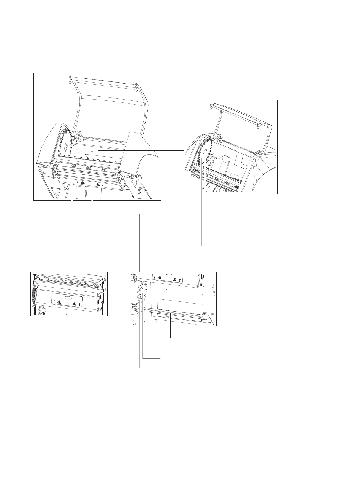
The Printing Mechanism
RIBBON REWIND MECHANISM
PRINT HEAD
RIBBON WINDOW COVER
NOTCH OF RIBBON REWIND WHEEL
RIBBON REWIND WHEEL
RIBBON
SUPPLY
MECHANISM
PAPER PRESS BAR
NOTCH OF RIBBON SUPPLY WHEEL
RIBBON SUPPLY WHEEL
5
Page 10
2 Printer Setup
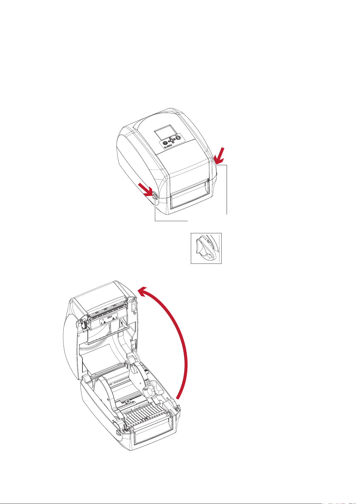
2.1 Open the Printer
Open the Printer Cover
Place the printer on a flat surface. Open the printer cover by pulling the cover release catches on both sides of the
printer and lift the printer cover.
Pull the catches toward the direction
RT700i
COVER RELEASE CATCHES
Pull the catches for opening the printer cover
Pull the catches toward the direction
Open the printer cover
6
Page 11
2 Printer Setup
2.2 Loading the Ribbon
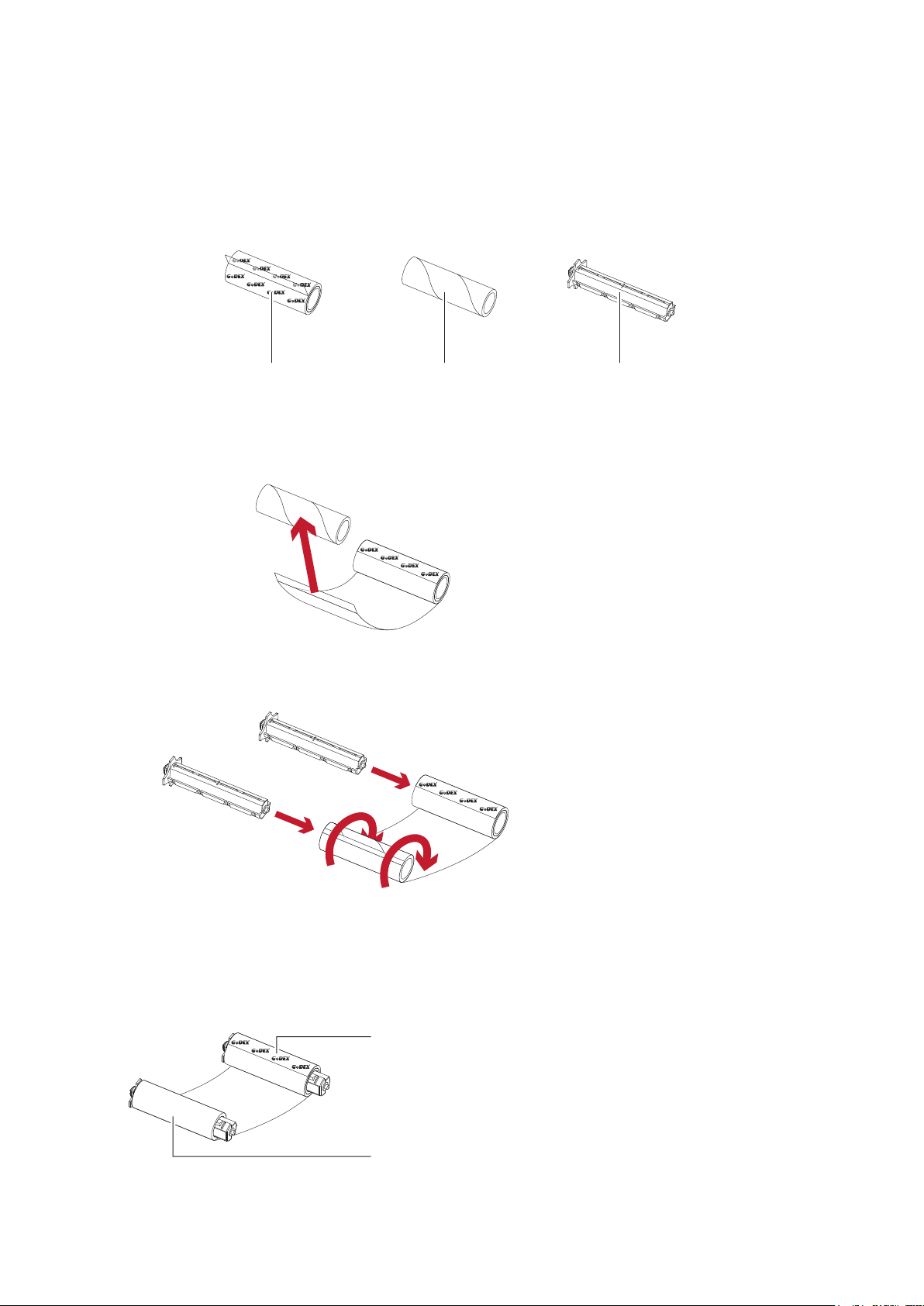
A New Ribbon Module Installation
EMPTY RIBBON COREA NEW RIBBON
1. Attach the ribbon to the empty ribbon core with the adhesive strip at the end of the ribbon.
Stick on empty ribbon core
2. Insert the ribbon hub into empty ribbon core and new ribbon. Wind the ribbon around the empty ribbon core
for 2 to 3 circles.
Insert the ribbon hub
RIBBON HUB
3. A ribbon module is assembled as below.
A NEW RIBBON MODULE
Wind the ribbon around the core
RIBBON SUPPLY MODULE
RIBBON REWIND MODULE
7
Page 12
2 Printer Setup
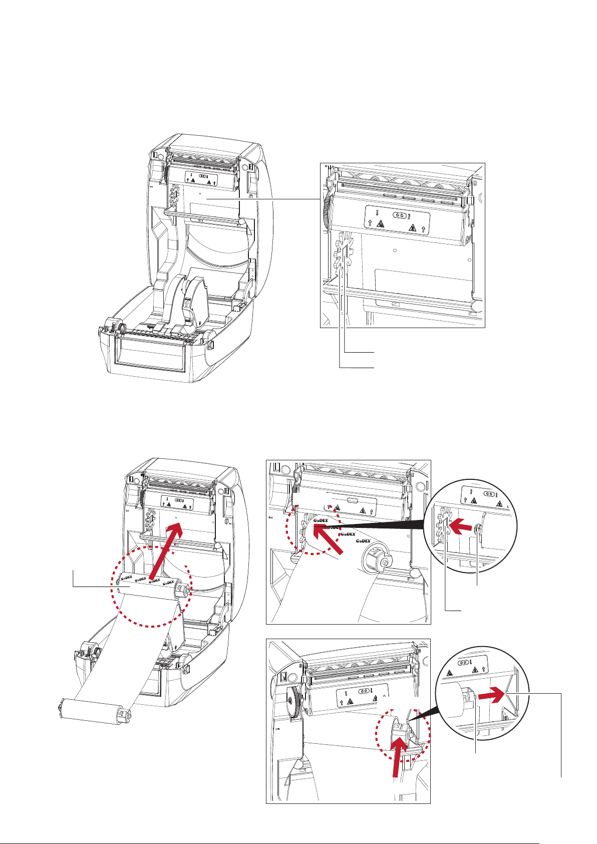
Load the Ribbon on the Printer
For Ribbon Supply Module
RIBBON SUPPLY MECHANISM
RIBBON SUPPLY SPINDLE FIXED SLOT
RIBBON SUPPLY WHEEL
1. Place the ribbon module into the printing mechanism. Please the left-hand side of ribbon supply spindle
fixed slot first. Make sure the holder of square fixed shaft is inserted into the notch. Then place the
right-hand side of ribbon positioning round shaft. Can be fixed ribbon supply module.
Left side
放入
RIBBON SUPPLY
MODULE
Place
Place
SQUARE FIXED SHAFT
RIBBON SUPPLY SPINDLE
FIXED SLOT
Right side
POSITIONINGROUND SHAFT
Place
POSITIONING HOLES
8
Page 13
2 Printer Setup
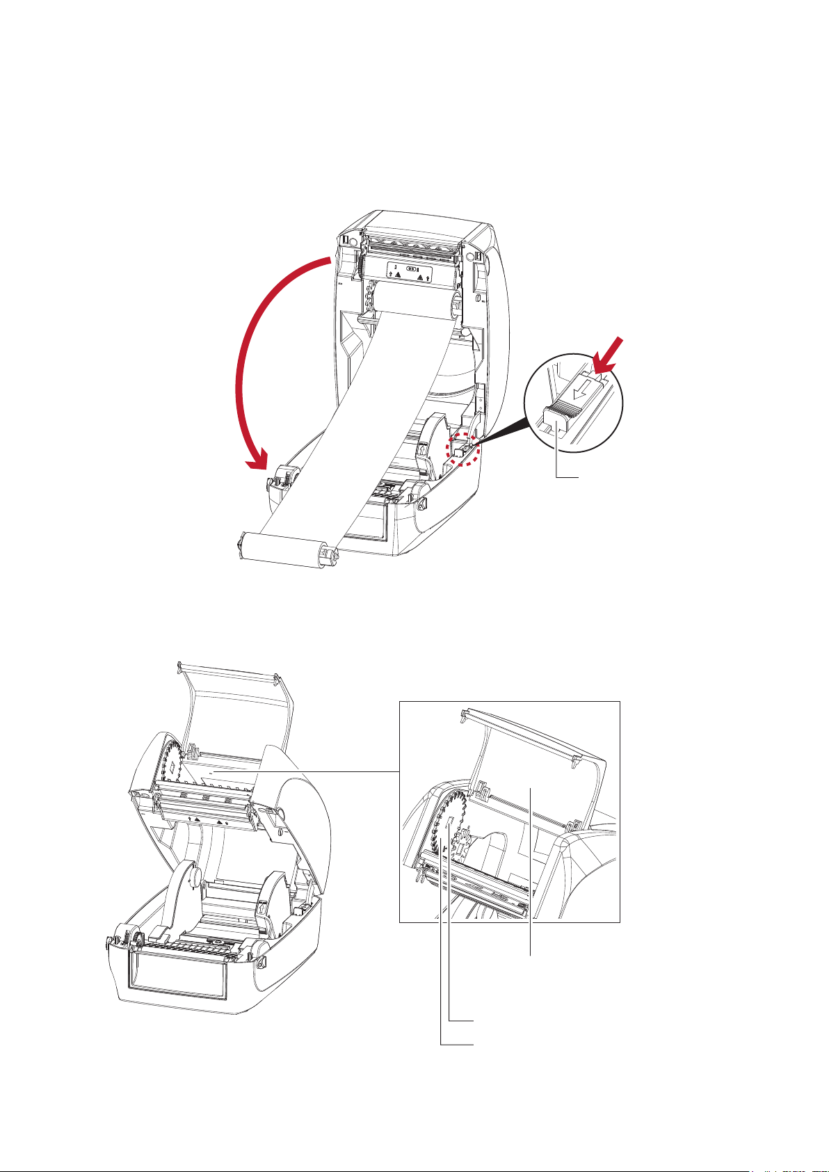
2. The ribbon supply module loading is completed. Pull the ribbon.
Push the release catch forward to unlock it. Close the printer cover.
Close the printer cover
For Ribbon Rewind Module
2
1
Push
RELEASE CATCH
Release catch for closing
the printer cover
RIBBON REWIND MECHANISM
RIBBON WINDOW COVER
The cover for Ribbon rewind mechanism
RIBBON REWIND SPINDLE FIXED SLOT
RIBBON REWIND WHEEL
9
Page 14
2 Printer Setup
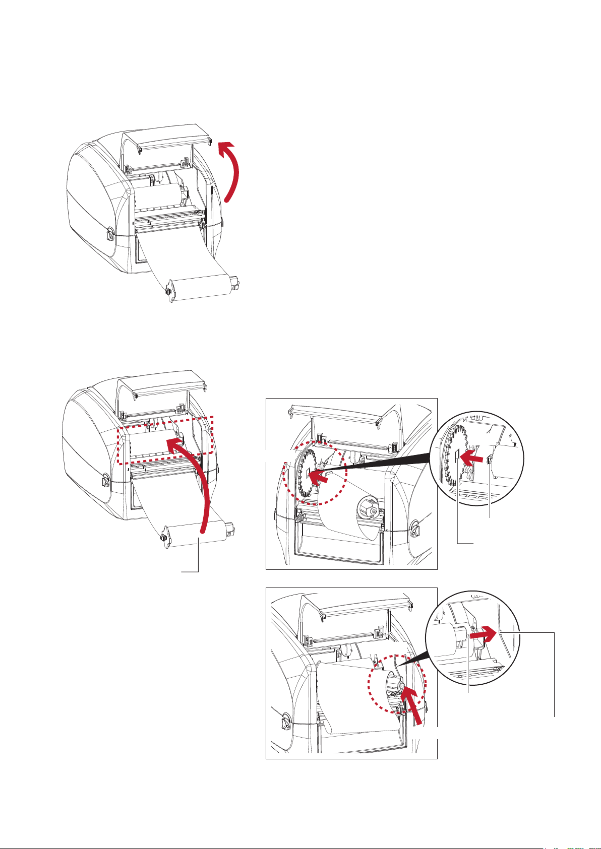
1. Open the cover of ribbon window.
Open the cover of ribbon window
2. Please the left-hand side of ribbon rewind spindle fixed slot first.
Make sure the holder of square fixed shaft is inserted into the notch. Then place the
right-hand side of ribbon positioning round shaft. Can be fixed ribbon rewind module.
RIBBON REWIND
MODULE
Place
Left side
Place
Right side
Place
SQUARE FIXED SHAFT
RIBBON REWIND
SPINDLE FIXED SLOT
POSITIONING ROUND SHAFT
Place
POSITIONING HOLES
10
Page 15
2 Printer Setup
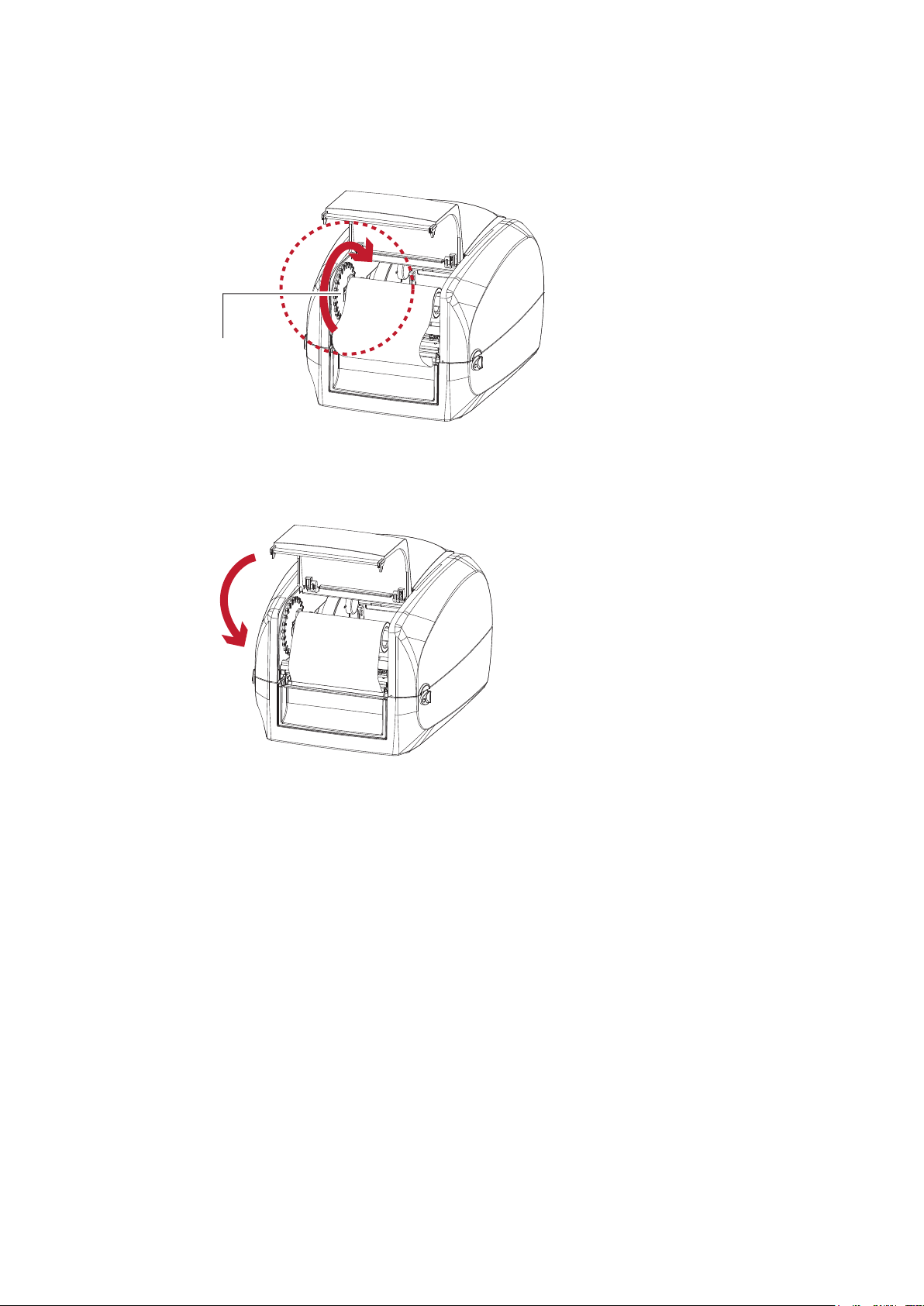
3. Turn the ribbon rewind wheel to tighten the ribbon until it has no wrinkles.
Rotate backward
RIBBON REWIND WHEEL
4. Close the cover of ribbon window.
The ribbon loading is completed once the ribbon supply module and ribbon rewind module are assembled
correctly.
Close the cover
of ribbon window
11
Page 16
2 Printer Setup
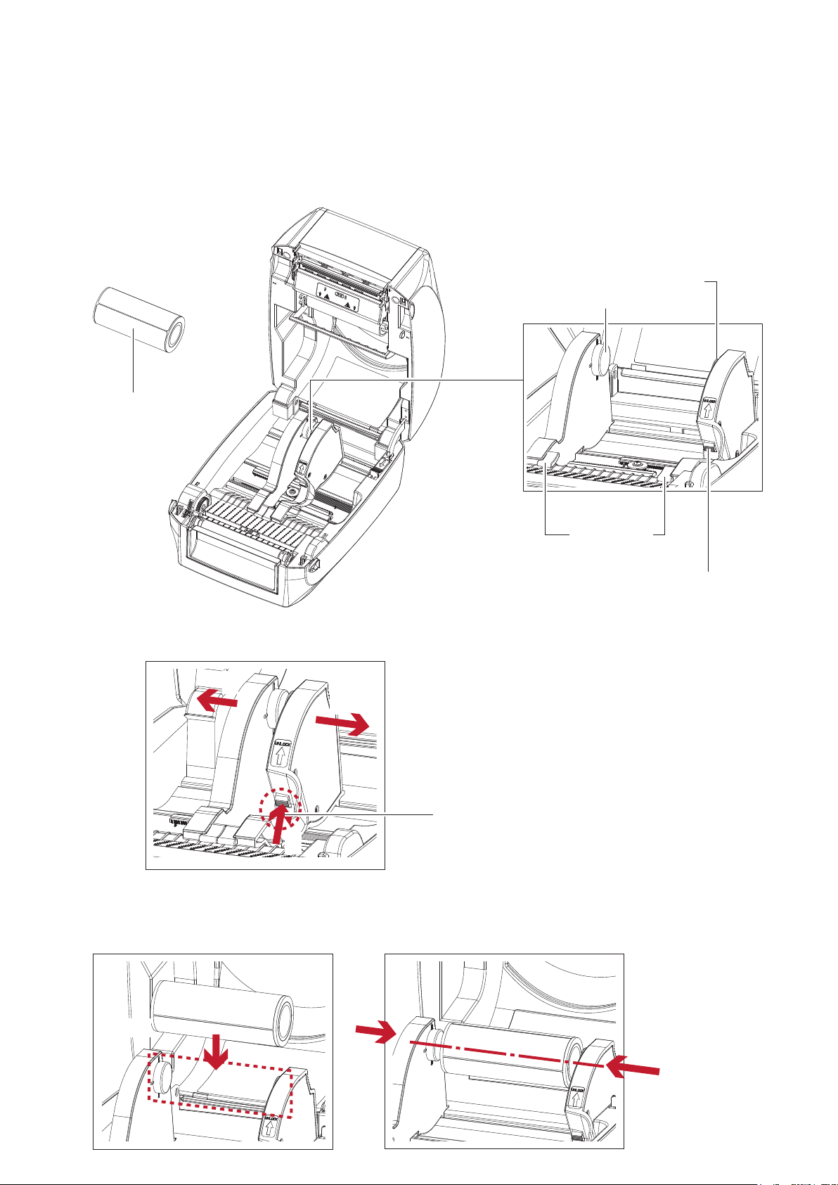
2.3 Loading the Label Roll Module
Loading the Label Stock on the Printer
LABEL STOCK
LABEL SUPPLY HUB
Set of 2
LABEL
SUPPLY
MODULE
LABEL GUIDE
Set of 2
1. Press the ribbon catch and pull to open the label supply hub.
2
2
RELEASE CATCH
Release catch for opening the label supply hub
1
2. The label roll into the label supply module and align the label supply hub.
Moving the label supply hub. The label roll is indeed installed in the label supply hub.
RELEASE CATCH
Release catch for opening
the label supply hub
Place
12
Page 17
2 Printer Setup
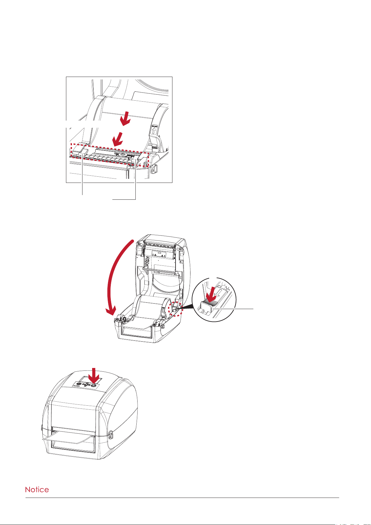
3. Feed the Label through the label guides. The label guides will help to prevent the label swaying.
(Press release catch removable label guide.)
Through the label guides
LABEL GUIDE
Set of 2
4. Unlock the release catch to close the printer cover.
2
Close the printer cover
1
RELEASE CATCH
Release catch
for closing the printer cover
5. Press the FEED key and make sure the label is fed smoothly. The label loading is completed now.
RT700i
**** Please keeps the rack gear clean to ensure the smoothness of paper roll supply module.
13
Page 18
2 Printer Setup
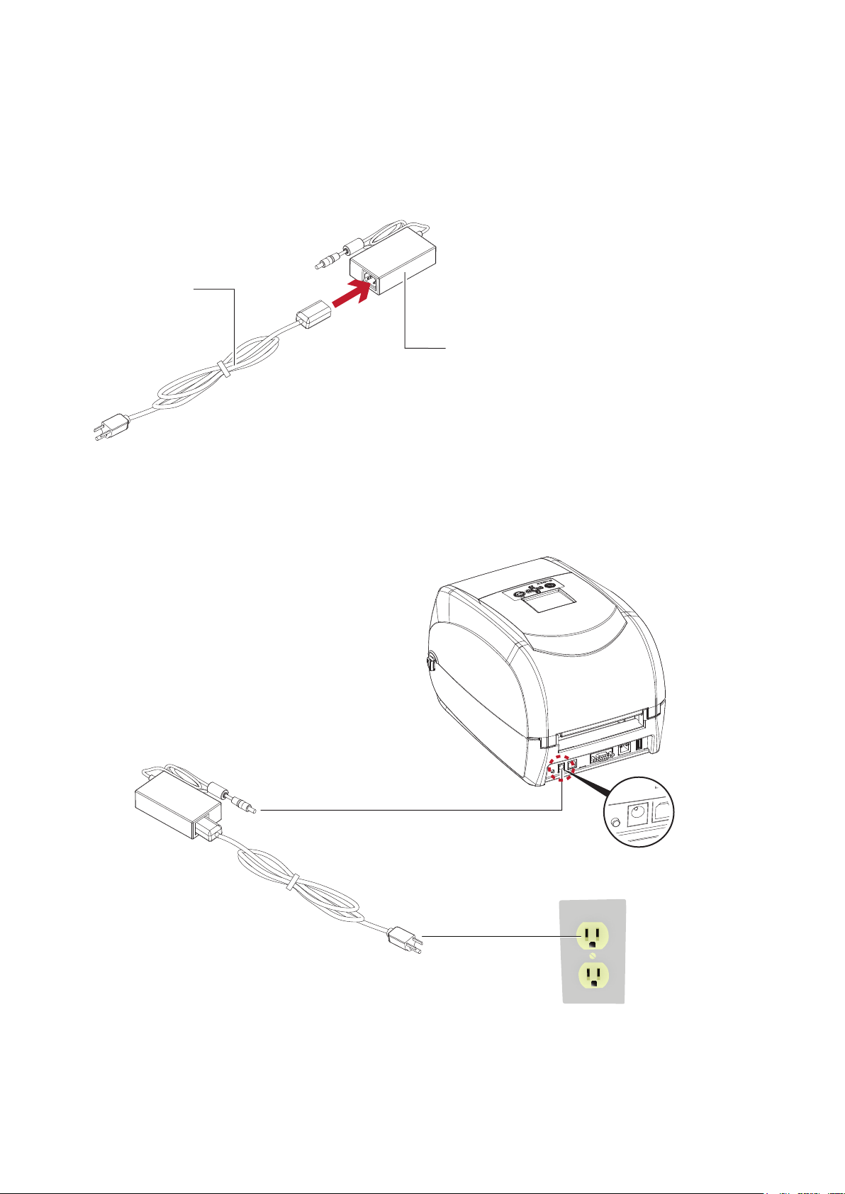
2.4 Connecting the Printer to the Host Computer
1. Please make sure that the printer is switched off.
2. Connect the power cord to the AC adapter.
POWER CORD
AC ADAPTER
Connect the jack of the power adapter to the printer and connect the plug of the power adapter to the socket
of the wall.
POWER ADAPTER
JACK
RT700i SERIES BARCODE PRINTER
RT700i
SLOT
THE WALL
PLUG
SOCKET
14
Page 19
2 Printer Setup
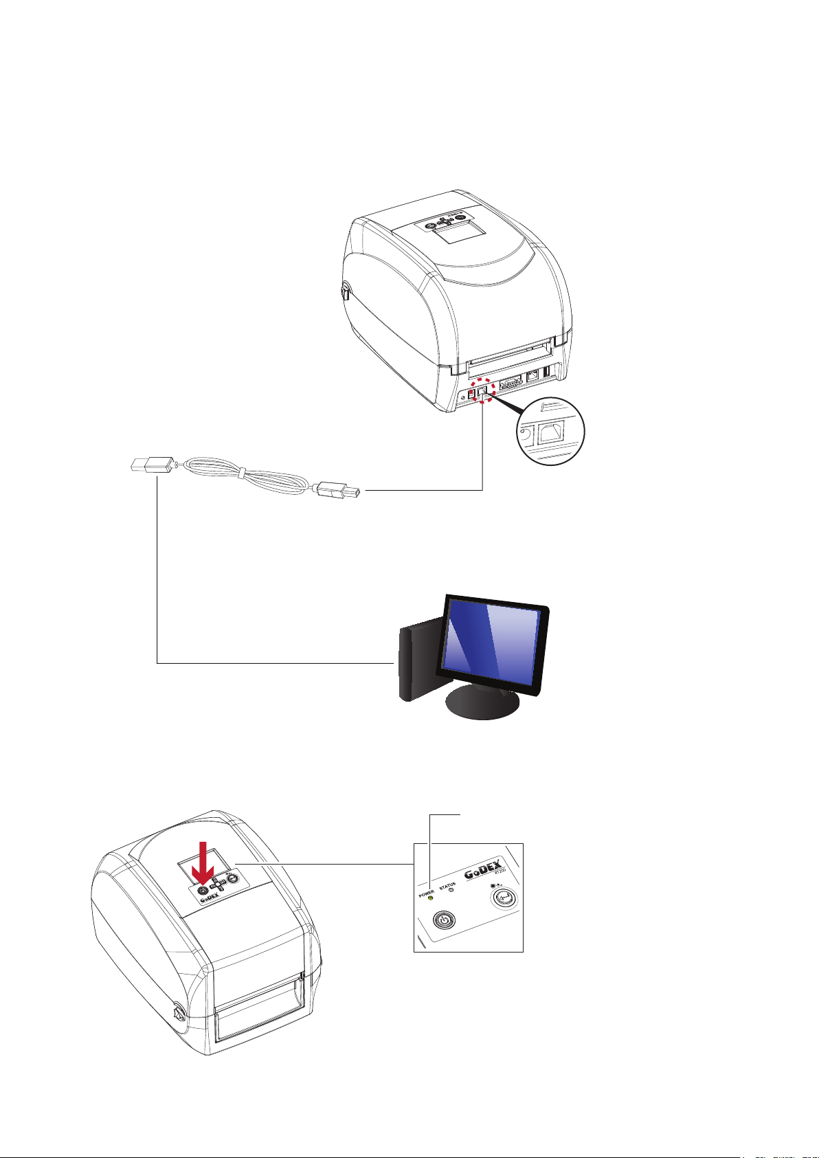
3. Connect the USB/serial cable to the printer and host computer.
RT700i SERIES BARCODE PRINTER
RT700i
USB CABLE
PLUG
PLUG
SOCKET
USB PORT
PC
4. Pressing the power button. The power LED indicator should now lights up.
Pressing the power button
POWER LED INDICATOR
OPERATION PANEL
RT700i
15
Page 20
2 Printer Setup
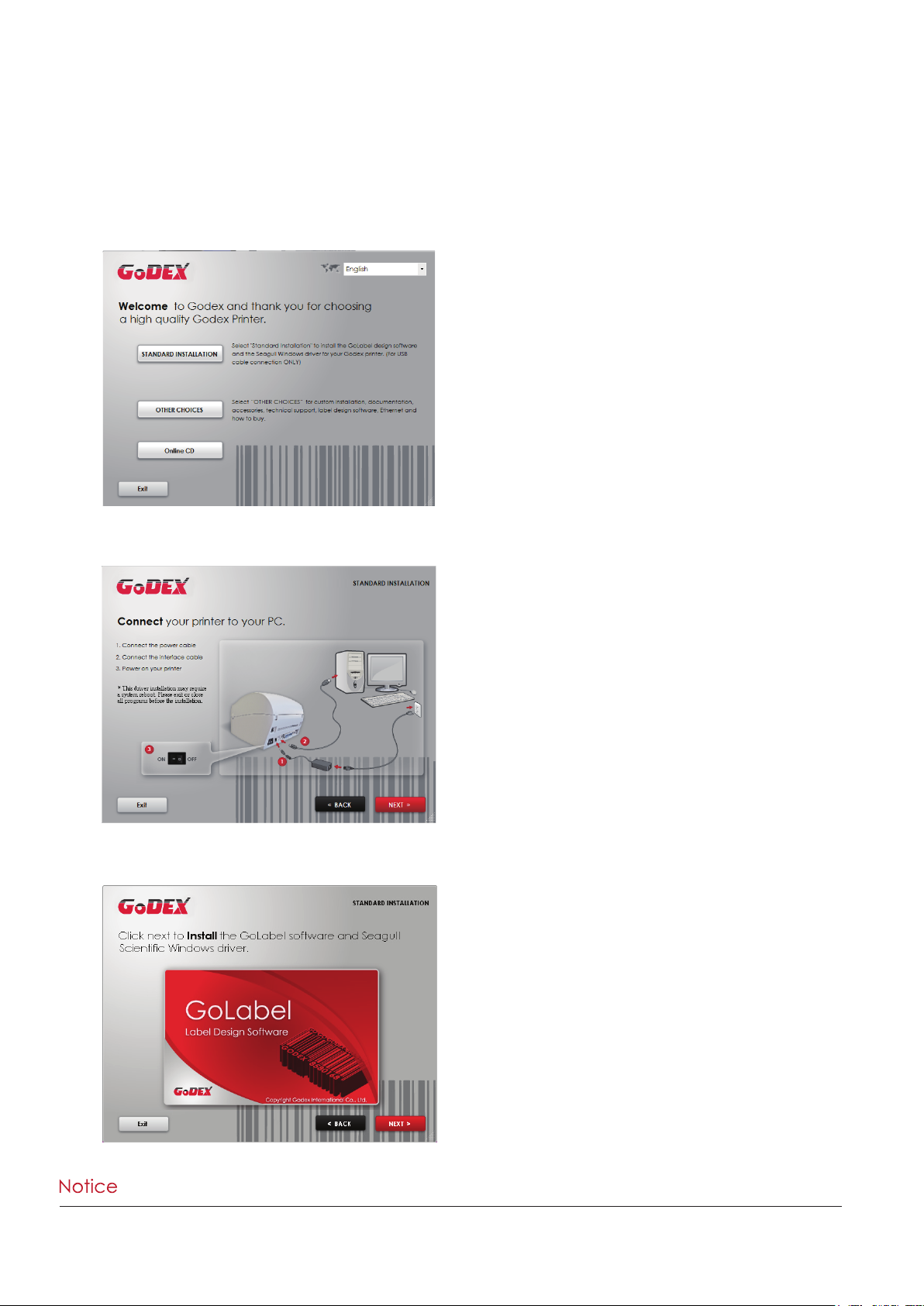
2.5 Installing Printer Driver and GoLabel with Super Wizard CD
1. Insert the Super Wizard CD in the CD/DVD drive of the host computer and the program should pop up
automatically. You will see the Welcome screen first. On the Welcome screen, choose “Standard Installation”.
2. The wizard will then ask you to make sure your USB and power cables are connected and that the power is
turned on. Make sure that is done and then click “Next”.
3. The next screen you will see is, “Install the GoLabel Software and Windows driver”. Click “Next” to continue.
****If the Super Wizard program did not run automatically, you can either turn on the “Auto-run” setting for your
CD/DVD driver or double-click the icon of CD/DVD driver to run the program.
16
Page 21
2 Printer Setup
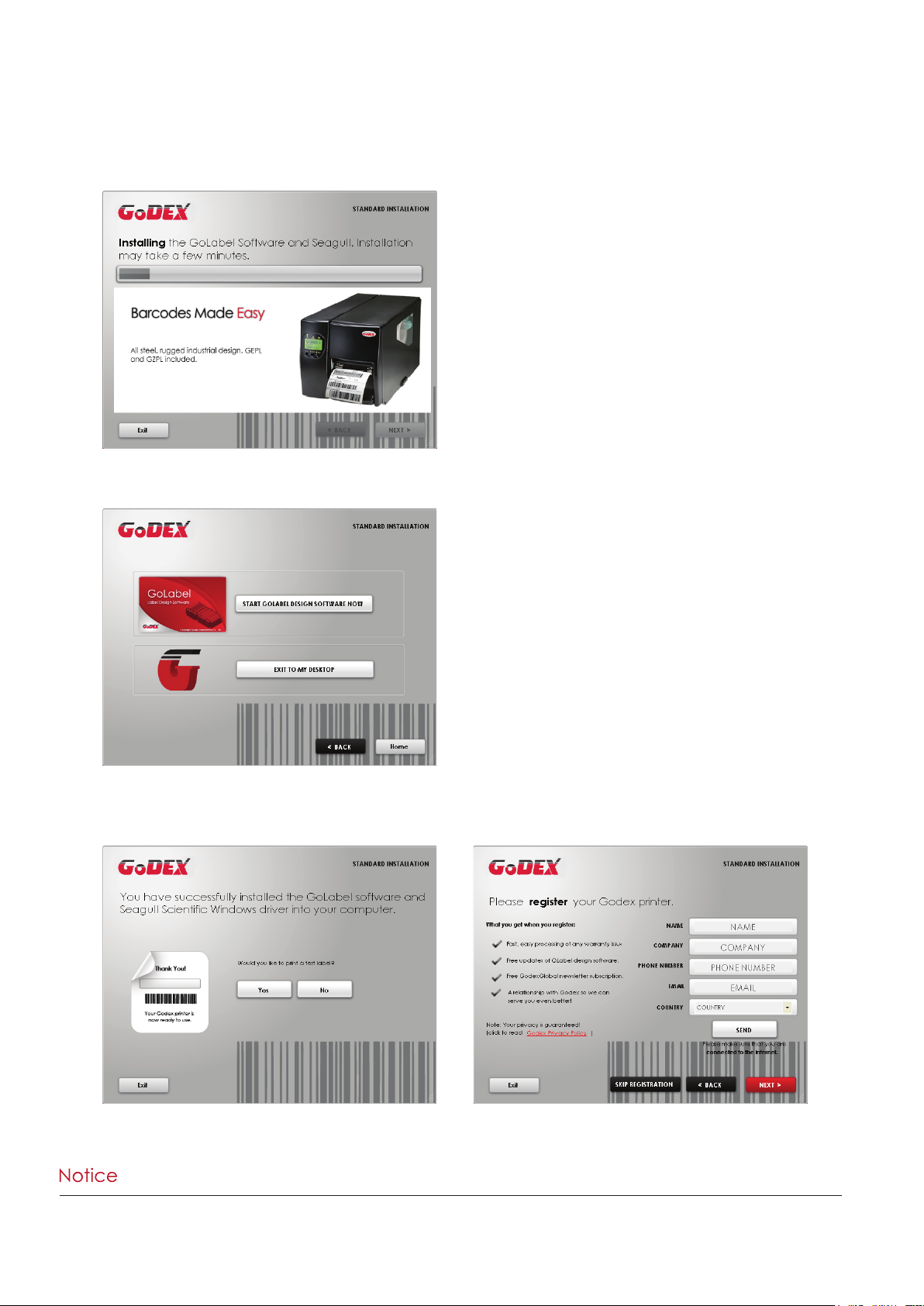
4. As the printer driver and GoLabel are installing, a screen will display a progress bar.
5. Once the installation is complete, you can start to make and print labels with GoLabel or throug the printer driver.
6. As the optional steps, you can also print a test label or register your printer during the “Standard Installation”
procedure.
****If you need more resources, tools or reference documents, you can also find them on Super Wizard CD. Just click
“Other Choices” on Welcome Screen to access the files.
17
Page 22
2 Printer Setup
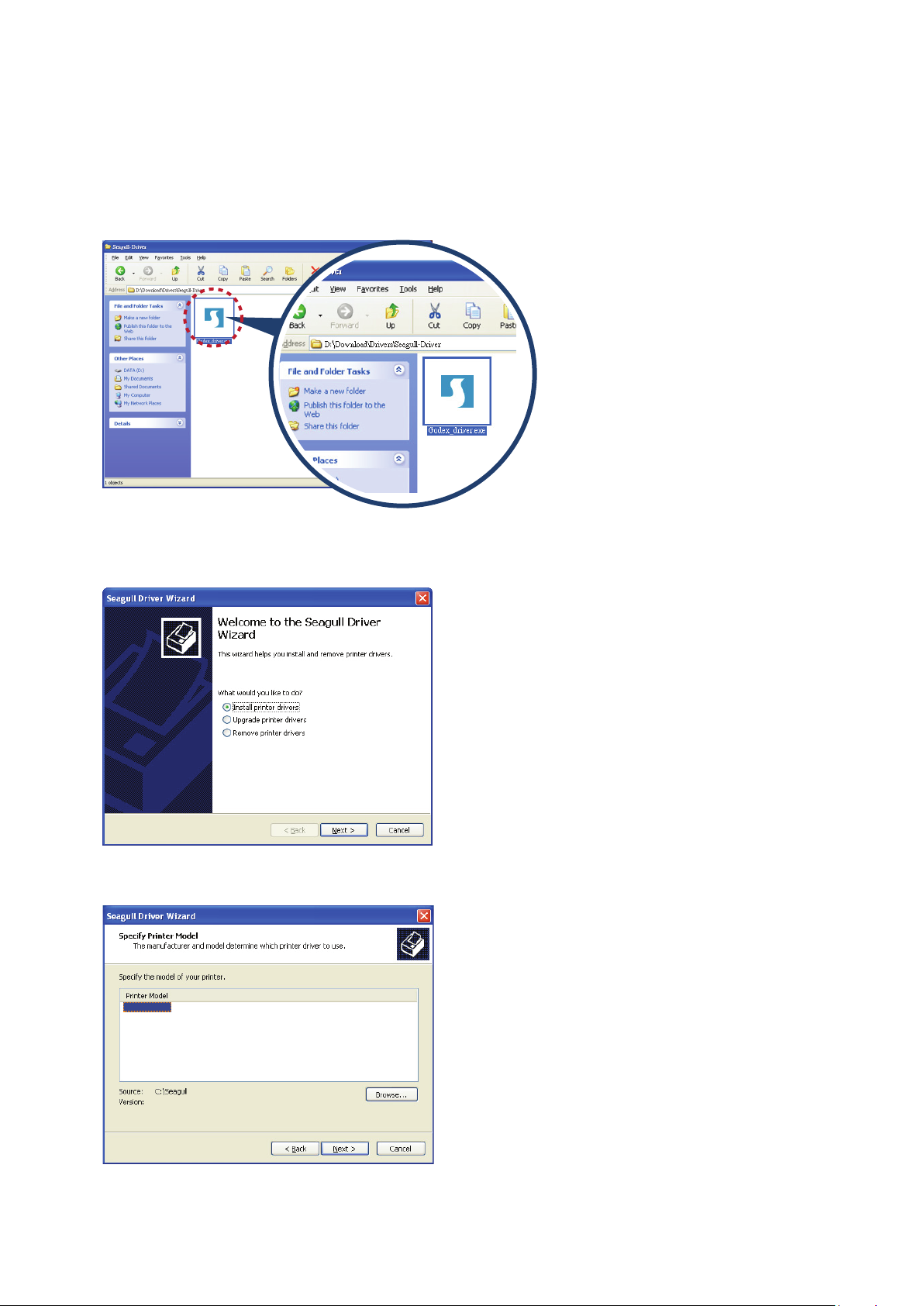
Installing Printer Driver Directly from CD Folder
1. Insert the product CD in the CD/DVD drive of the host computer and open the "Seagull Drivers" folder on the CD.
Select the icon for the driver file and click it to start the installation.
2. Follow the instructions on the screen. The Driver Wizard guides you through the installation procedure.
Select "Install printer drivers".
3. Specify your printer model.
Godex RT700i
18
Page 23
2 Printer Setup
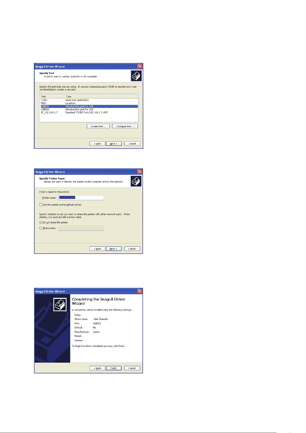
4. Specify the port used to connect the printer to the host computer.
5. Enter a printer name and assign the appropriate rights.
Godex RT700i
Godex RT700i
6. Once the installation is complete, a summary of the printer settings is displayed.
Check whether the printer settings are correct and click "Finish" to start copying the driver files.
Wait until copying is complete, then finish the installation.
Godex RT700i
Godex RT700
19
Page 24
2 Printer Setup
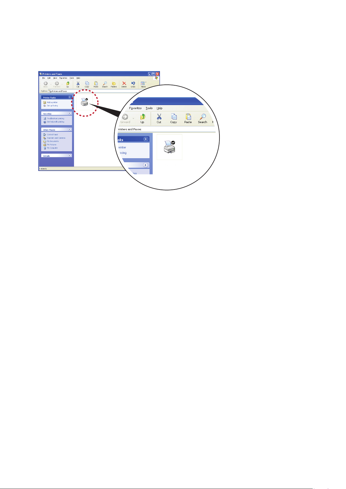
7. Once the driver installation is complete, the new printer should appear in the "Printers and Faxes" folder.
Godex RT700i
Godex RT700i
20
Page 25
3 Printer Setting and Control
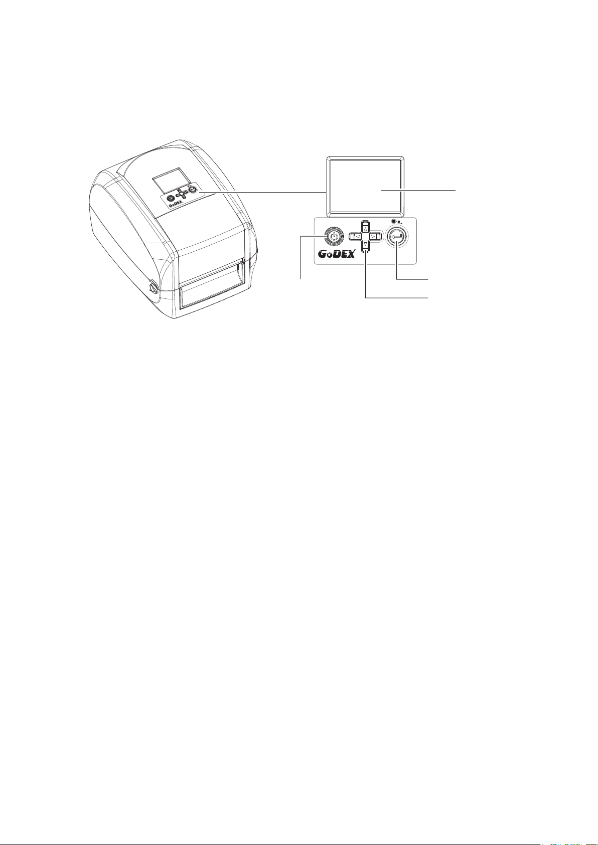
3.1 Operation Panel
Operation Panel Introduction
OPERATION PANEL
RT700i
RT700i
POWER BUTTON
POWER Button
Press the POWER button to turn on the printer, and the START UP SCREEN appears. The printer is on “ready to print”
status, the LCD screen should display the message “READY“ on the screen.
When printer is turned on, keep pressing the POWER button for 3 second will turn the printer off.
FEED Button
When you press the FEED button, the printer moves the label to the defined stop position.
If you are using continuous labels, pressing the FEED button will move label stock until you release the button again.
If you are using individual labels, pressing the FEED button will move only one label.
If the label does not stop at the correct position, you need to run the auto-detection function on the label stock, please see Section 3.4 Label
Calibration and Self Test.
LCD SCREEN
FEED BUTTON
DIRECTION KEY
PAUSE PRINTING_FEED Button
Pressing the FEED button during printing will interrupt printing, and the LCD display message “PAUSE...”.
When the FEED button is pressed again, the printer resumes printing. Example: While a 10-label print job is running,
you press the FEED button to pause the printer. Two of the labels have been printed. To resume printing and print the
remaining eight labels, you will need to press the FEED button again.
CANCEL PRINTING_FEED Button
Press and hold the FEED button for 3 seconds during printing, the current print job will be cancelled.
Example: While a 10-label print job is running, you press the FEED button. Two of the labels have been printed.
The print job is cancelled and the remaining eight labels will not be printed.
021
Page 26
3 Setting and Control for Operation Panel
3.2 LCD Interface Introduction
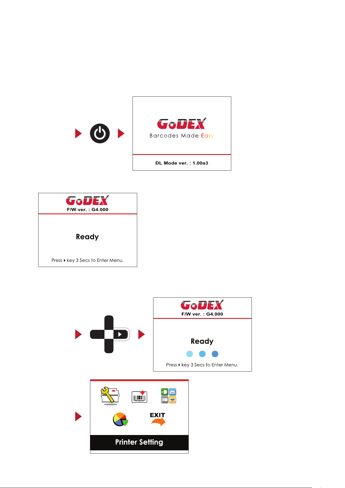
Getting Started
Press the POWER button to turn on the printer, and the START UP SCREEN appears.
Power on
If the printer is on “ready to print” status, the LCD screen should display the message “Ready“ on the screen.
Please keep pressing button and wait for the timer to be filled, then the LCD interface will enter into the MAIN
PAGE for SETTING MODE. You can make various setting functions in SETTING MODE.
Enter Main page
22
Page 27
3 Setting and Control for Operation Panel
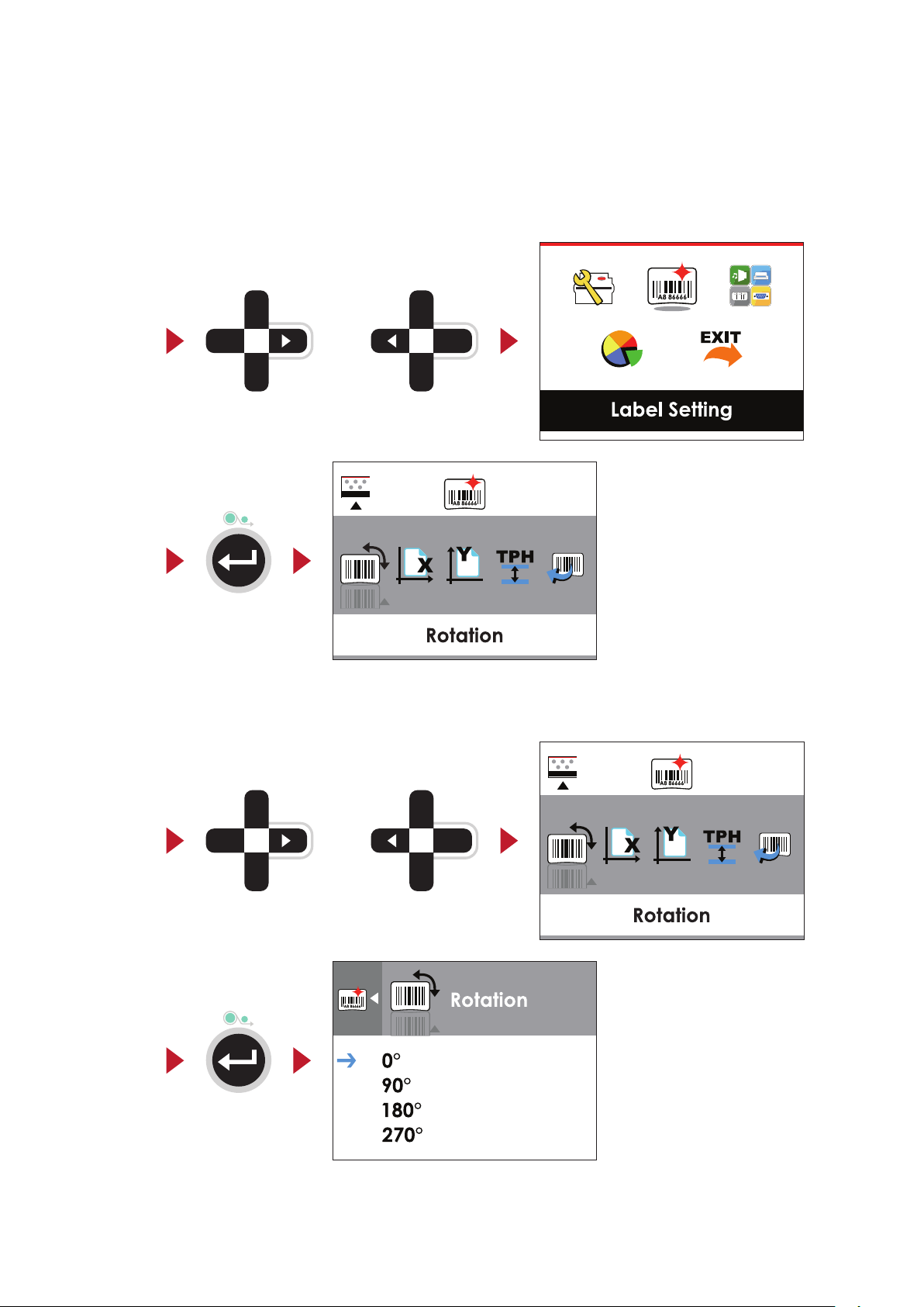
Operations on Setting Page
On MAIN PAGE, press or button to move the cursor and select the functions.
Select a designated function and press FEED button, you will enter the SETTING PAGES for the function.
Select
Enter
On SETTING PAGES, press or button to select the setting items.
Select a designated function and press FEED button, you will enter the SETTING VALUE PAGES for the function.
or
Enter
orSelect
23
Page 28
3 Setting and Control for Operation Panel
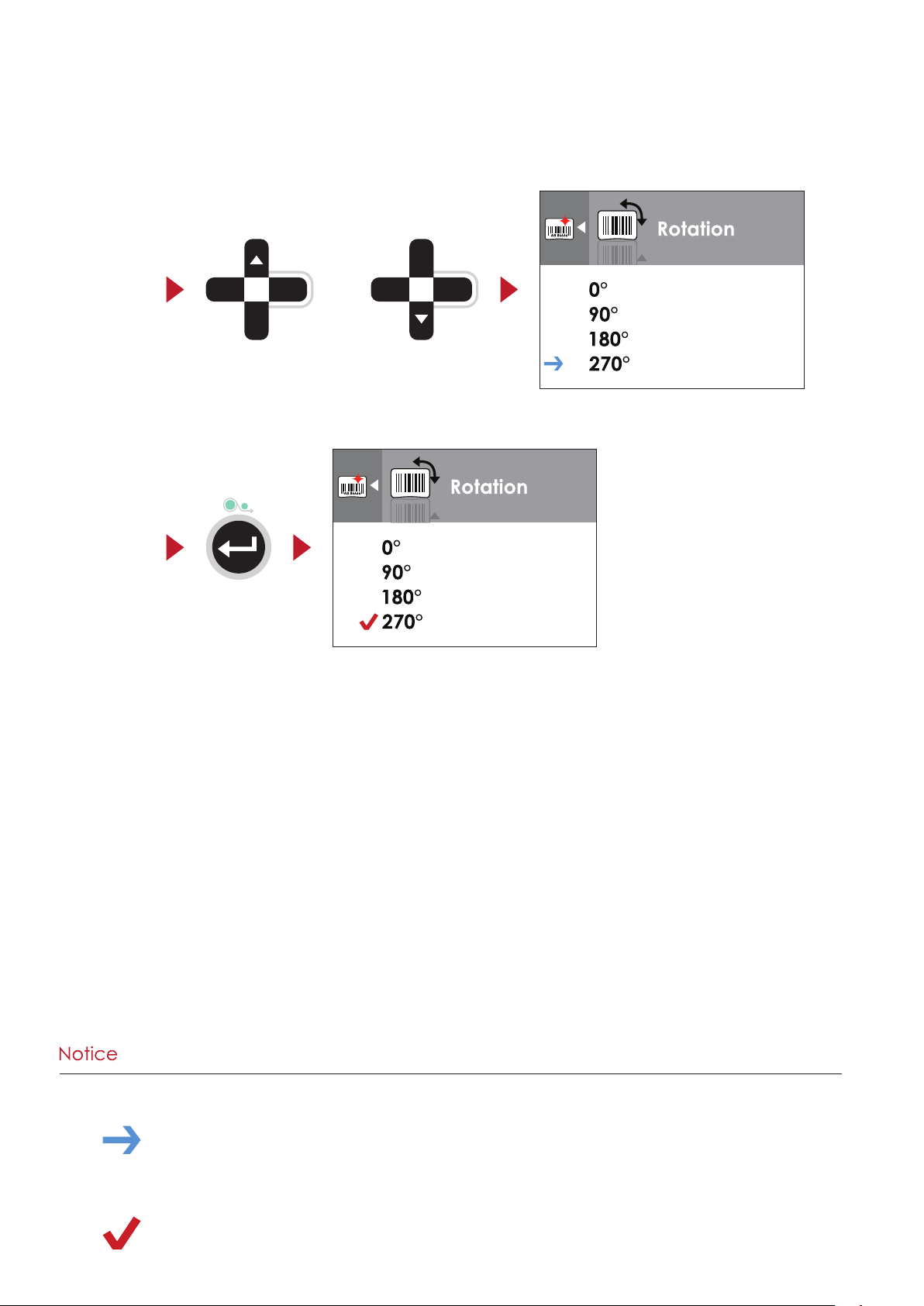
On SETTING VALUE PAGES, press or button to change the setting values.
Select
Press FEED button will apply the setting value you just selected, and the red tick will appear to mark the value.
Apply
or
**** The blue arrow indicates the value you are selected.
**** The red tick indicates that the selected value is applied now.
24
Page 29

3 Setting and Control for Operation Panel
Exit from Current Page to Ready Status
The icon on top-left corner displays the capture of upper level screen and also guides you back to upper level with
left or up arrow.
NAVIGATION ICON
On SETTING VALUE PAGES, press button will go back to the upper level screen.
Back to the Setting page
On SETTING PAGES, press button will go back to the MAIN PAGE screen.
Back to the Main page
25
Page 30

3 Setting and Control for Operation Panel
3.3 LAN Setting
Operations on Setting Page
On MAIN PAGE,press or button to move the cursor and select the functions.
Select a designated function and press FEED button, you will enter the SETTING PAGES for the function.
Select Device
Enter LAN Setting
On LAN Setting PAGE,press or button to select the setting items.
or
Device
Select a
designated funcition
Select DHCP and press FEED button, you will be able to setup DHCP function
or
26
Page 31

3 Setting and Control for Operation Panel
The default of DHCP is Disable. ,Press or button to change the setting values.
Select to enable DHCP
Press FEED button twice to save the setting.
Press FEED once to exit.
Press FEED again to save
and return to previous
SETTING PAGE.
27
Page 32

3 Setting and Control for Operation Panel
3.4 LCD Password
Operations on Setting Page
On MAIN PAGE, press or button to move the cursor and select the functions. Seclect a designated function
and press FEED button, you will enter the SETTING PAGE for the function.
Select Device
Enter LCD Password
The default of LCD Setting is Disable. Press or button to change the setting values.
or
Device
Select button to
Enable Password function
28
Page 33

3 Setting and Control for Operation Panel
Select button again to
setup the password
Press FEED button twice to svae the setting
Press FEED button onece to exit.
Press FEED button again to save
reture to previous SETTING PAGE
and
29
Page 34

3 Setting and Control for Operation Panel
3.5 LCD Interface Function
Main Page
Setting items for printer, ex. Printing speed, darkness.
Printer Setting
Also includes a Printing Wizard for your ease of printing.
Label Setting
Device
Analysis
Exit
Setting items for printing label, ex. Rotation, Printing position offset.
Option modules and connection port settings.
Self-Diagnose functions for printer, ex. TPH testing, self-test page printing.
Exit from Setting Mode.
30
Page 35

3 Setting and Control for Operation Panel
English
Speed
2-5 or 7
Darkness
0-19
Label with Gaps
Label with Marks
Continuous
Direct Thermal
Thermat Transfer
Tear-off Position
0-40
Darkness
0-19
Speed
2-5 or 7
Auto Select
See-Through
Reflective
Label with Gaps
Label with Marks
Continuous
Direct Thermal
Thermat Transfer
Tear-off Position
0-40
Apply
Cancel
850
852
437
860
863
865
857
861
862
855
866
737
851
869
Win 1252
Win 1250
Win 1251
Win 1253
Win 1254
Win 1255
Win 1257
0°
90°
180°
270°
Horizental Offset
-100 - 100
Vertical Offset
-100 - 100
Start Offset
-100 - 100
001 Form Name
002 Form Name
Setting Items in Setting Mode
Printer Setting
LCD Language
Wizard
Media Type
Printer Mode
Sensor
Printing Mode
Top of Form
Deutsch
繁體中文
简体中文
Français
Español
日本語
Italiano
Pусский
Türk
Media Detection
Media Type
Label Setting
Setting
Codepage
Rotation
Recall Label
31
Page 36

3 Setting and Control for Operation Panel
Apply
Cancel
None
Cutter
Label Dispensor
Applicator
Apply
Cancel
4800 bps
9600 bps
19200 bps
38400 bps
57600 bps
115200 bps
Non
Odd
Even
7 bits
8 bits
1 bits
2 bits
Apply
Cancel
YYYY/MM/DD
HH:MM:SS
Apply
Cancel
Apply
Cancel
Apply
Cancel
Apply
Cancel
Apply
Cancel
Apply
Cancel
Apply
Cancel
Apply
Cancel
Apply
Cancel
Apply
Cancel
Exit
Buzzer
Device
Optional Setting
LAN Setting
LCD Password
Serial Port Setting
RTC Setting
Bluetooth Setting
Option
Pre-Printing
Part NO.
DHCP
Default Gateway
Dynamic IP
Subnet Mask
Baud Rate
Parity
Data bits
Stop bits
Clock Display
RTC Setting
Clear Bind
Make Device
Visible
SSP
09100
Disable
Enable
192.168.000.254
192.168.102.076
255.255.255.000
Disable
Enable
Enable
Disable
Enable
Disable
Enable
Disable
PIN Code 0000
Search Devices
Analysis
Exit
Calibration
Self-test
TPH Testing
Reset to Default
Label Format
Graphic
Bitmap Fonts
Clear Memory
True Type Fonts
Asian Fonts
ALL
32
Page 37

3 Setting and Control for Operation Panel
Appears on the NAVIGATION ICON of Setting
pressing “LEFT“ key.
Appears on the NAVIGATION ICON of Setting
by pressing “UP“ key.
On Setting Value pages, press “RIGTH“ key to
change.
For locked value, press “RIGHT” key again to
unlock the value.
Status of LCD Interface
When printer is on standby status (ready to print), the LCD interface will display “Ready” on screen.
You can only print on this “Ready“ status.
If there is any printers error, the LCD screen will display the error screen to show the type of error.
You can fix the error according the notice.
WARNING ICON
Icon Definition
To upper level
To upper level
Lock
Unlock
Scroll the value
ERROR ICON
Check Ribbon
Pages. It guides you back to upper level by
Value Pages. It guides you back to upper level
lock the value for preventing unexpected
On Setting Value pages, press “UP“ or “DOWN“
key to scroll the values for your selection.
ERROR DESCRIPTION
33
Page 38

3 Printer Setting and Control
3.6 Label Calibration and Self Test
Label Calibration
The printer can automatically detect and store label height.
That means the host computer does not need to transmit the label height to the printer.
Self Test
Self-test function lets you check whether the printer is functioning normally.
Here is how you run the label size calibration and self test.
1. Check that the label stock is loaded correctly.
2. Turn off the printer.
3. Turn the printer on again, keeping the FEED button pressed. When the LED starts to flash red, release the FEED
button. The printer will now measure the label stock and store the label height.
4. Once the printer has successfully measured the label stock, it will print a self-test label.
The contents of a self-test printout are listed below.
Model & Version
USB ID setting
Serial port setting
MAC address of Ethernet port
IP protocol setting
IP address of Ethernet port
Gateway setting
Netmask setting
Number of DRAM installed
Image buffer size
Number of forms
Number of graphics
Number of fonts
Number of Asian fonts
Number of Databases
Number of Scalable fonts
Free memory size
Speed, Density, Ref. Point, Print direction
Label width, Form length, Stop position
Cutter, Label Dispenser, Mode
Sensor Setting
Code Page
RT700i:GX.XXX
USB S/N:12345678
Serial port:96,N,8,1
MAC Addr:xx-xx-xx-xx-xx-xx
DHCP Enable
IP xxx.xxx.xxx.xxx
Gateway xxx.xxx.xxx.xxx
Sub-Mask xxx.xxx.xxx.xxx
##################################
1 DRAM installed
Image buffer size:1500 KB
0000 FORM(S) IN MEMORY
0000 GRAPHIC(S) IN MEMORY
000 FONT(S) IN MEMORY
000 ASIAN FONT(S) IN MEMORY
000 DATABASE(S) IN MEMORY
000 TTF(S) IN MEMORY
4073 KB FREE MEMORY
^S4 ^H8 ^R000 ~R200
^W102 ^Q100,3 ^E18
Option:^D0 ^O0 ^AD
Reflective AD:1.96 2.84 2.49[0.88_23]
Code Page:850
34
Page 39

3 Printer Setting and Control
Label Calibration Button
A hardware button to make a Label Calibration while printer encountering ‘’Media Error’’ during the cases when first-time
printer start up or change label or ribbon to another type, such as change using gap label to continuous or black mark
labels.
RT700i
CALIBRATION BUTTON
Press
Press C-button for 2 seconds, it will make an auto-sensing to calibrate the label and ribbon’s parameters.
Press
****Press C-button is equivalent to the auto-sensing command ‘’~S,SENSOR’’ that will cancel on-printing-job and make the
Label Calibration immediately.
35
Page 40

3 Setting and Control for Operation Panel
Operation Panel
Status
Type
Beeps
Description
Solution
3.7 Error Alerts
In the event of a problem that prevents normal functioning of the printer, you will see an error message on LCD
screen and hear some beep signals. Please refer to below table for the error alerts.
Printhead up (Open)
OPERATION PANEL
RT700i
Print Head Error 2 x 4 beeps
POWER BUTTON
The printing mechanism is not
correctly closed.
LCD SCREEN
FEED BUTTON
DIRECTION KEY
Open the print mechanism and
close it again.
Check Ribbon
Check Media
Print Head Error None
Media Error 2 x 3 beeps
Media Error 2 x 2 beeps
High temperature at the print
head.
No ribbon is installed and the
printer displays an error.
The ribbon is finished or the label
supply hub is not moving.
No paper is detected.
Paper is finished. Replace the label roll.
Printer feed problem.
Once the print head has cooled
down, the printer switches to
standby mode.
Make sure that the printer is set to
direct thermal printing mode.
Replace the ribbon roll.
Make sure that the label sensor is
positioned correctly. If the sensor
still does not detect the paper,
run the auto-detection function
again.
Possible reasons: the print medium
has become trapped around the
rubber roll; the sensor cannot
detect a gap or black mark
between the labels; there is no
paper. Please reset the sensor.
36
Page 41

3 Setting and Control for Operation Panel
Operation Panel
Status
Type
Beeps
Description
Solution
File Error 2 x 2 beeps
The memory is full. The printer
prints the message "File System full
".
Unable to find file. The printer
prints the message "File Name not
found"
A file of the same name already
exists. The printer prints the
message "Duplicate Name".
Delete unnecessary data or install
additional memory.
Use the "~X4" command to print
all files. Then check whether the
files exist and whether the names
are correct.
Change the name of the file and
try storing it again.
37
Page 42

3 Printer Setting and Control
3.8 USB Host
Definition : USB Host port supports either device:USB memory stick, keyboard or scanner.
Purpose
USB memory stick : It extends the user memory space up to 32GB for Graphic, Font, Label Format, DBF and Command
files downloading. The printer’s Firmware also can be updating if copy new version of Firmware into USB memory stick.
Connecting an USB keyboard to printer for ‘’ Standalone’’ mode operation.
Plug-in an USB scanner to operate the printer in ‘’Standalone’’ mode.
Usage of Extended Memory
USB memory stick : It supports hot-plugging function; printer will create a Folder ‘’\LABELDIR’’ and switch ‘’User Flash’’
to ‘’ Extended Memory‘’ automatically while user plugs an USB memory stick into a GoDEX ‘’i’’ model printer.
Connect the USB Stick plugged -in printer to PC via USB Device or Ethernet port and run ‘’GoLabel’’ software to
download Graphic, Font, Label Format, DBF and Command files to the printer.
Detail download procedures, please refer to ‘’GoLabel On-line Help’’.
RT700i
Usage of Firmware Update
Remove USB memory stick from printer and plug-in it to a PC’s USB port; delete Firmware ‘’*.bin’’ file from
‘’\LABELDIR\FW’’ of USB memory stick if it existing; or create a Folder ‘’\LABELDIR\FW’’ to USB memory stick if it doesn’t
existing.
Copy a new version of Firmware ‘’xxxx.bin’’ to the Folder ‘’\LABELDIR\FW’’; and then remove USB and plug-in
back to the printer that going to update Firmware.
The printer will update the Firmware automatically when plug-it-into the printer and printer find-out the Firmware
in ‘’\LABELDIR\FW’’ is newer version.
Don’t remove the USB memory stick out while it’s under updating with ‘’Flash Writing...’’message that displays on
LCD panel.
38
Page 43

3 Printer Setting and Control
USB Keyboard
When plug-in an USB keyboard to the printer, LCD panel will display “Standalone Mode”, press the “Enter” key
on keyboard and “Feed” key in the printer to entering to the dialog for “Recall Label” operation.
Only the sub-dialog “Recall Label” is able operating by keyboard as follow definition:
1. Press “ESC” key to exist from “Standalone Mode” or back to previous dialog
2. Press “F1”, it will let the printer from “Ready” mode entering into “Standalone Mode”
3. Press “Enter”, “Arrow” and “Alphabetic” keys as the usual in PC that will perform the key-in function of
“Recall Label” in “Standalone Mode”.
Scanner
When plug-in an USB scanner to the printer, LCD panel will display “Standalone Mode”, press the “Feed” key
in the printer to entering the dialog of “Recall Label” operation. User performs the “Recall Label” function interactively
through the LCD panel, 4 direction keys, Feed key and Scanner.
Scanner is using in “standalone Mode” to scanning the “Serial Number, Variable” and Print Quantity while the printer
prompts a message on LCD panel and wait for data input.
** The USB Host port on ‘’i’’ ‘’x’’ model printer is without ‘’HUB’’ function.
** The USB Memory Stick supports with ‘’FAT32’’Disk Format and up to 32GB only. The certified venders are Transcend,
Apacer, Patriot, Consair and Kingston.
* The download function for Graphic, Font, Label Format, DBF and Command files is operated by GoLabel of PC and
must go through the a ‘’i’’ ‘’x’’ model printer itself.
* On a PC, user may copy entire folder’’\LABELDIR’’ from USB memory stick to PC or vice-versa. Copy a sub-folder or
individual file in ‘’\LABELDIR’’ to PC or vice-versa is not supported.
39
Page 44

3 Printer Setting and Control
3.9 Dump Mode Begin
For make sure provide us correct information for check what commands sentfrom the PC or software, please following below
steps,
STEP 1, Let the printer enter Dump Mode
For Desktop printer (RT200i / RT700i series, with LCD)
Just press and hold the key until LCD Display shows “DUMP MODE ”, then release the key.
STEP 2. Make sure pinter ready for print a label
STEP 3. Send a label or commands which met problem to the printer
STEP 4. Printer will print out a label with letters and numbers, please take a picture on them and send us by email.
To cancel (get out of) the Dump Mode, please press the FEED key, and then the printer will
automatically print “OUT OF DUMP MODE.” This indicates that the printer is back to the standby mode.
40
Page 45

4 NetSetting for Ethernet
4.1 Installing the NetSetting software
The NetSetting software is used to manage the network configurations when connecting the printer via Ethernet port.
It is available on product CD or can be downloaded from official website. To install the NetSetting, please follow
below steps.
1. Insert the product CD in the CD/DVD drive of the host computer and open the "Ethernet" folder on the CD.
2. Select the icon for the NetSetting installation file and click it to start the installation.
3. Follow the instructions on the screen. The Setup Wizard guides you through the installation procedure.
4. Specify the “Installation Folder".
5. Click ”Next” to start the installation.
6. Once the installation is completed; you will see the NetSetting icon on your desktop.
41
Page 46

4 NetSetting for Ethernet
4.2 The Interface of NetSetting
Click the NetSetting icon to start the program; you will see the start page as below. The start page will display the
basic information of connected printer and your PC.
ZX1200
Click the magnifier icon to search the Godex printers which are connected via Ethernet port in you network
environment. Once a connected Godex printer is detected, it will be listed on the start page.
There are six tabs on the top of interface which can configure different types of network settings. But for the data
security reason, you need correct password to enter the configuration pages.
**** The default password is “1111”, you can change the password later from the “IP Setting” tab.
42
Page 47

4 NetSetting for Ethernet
IP Setting
The IP Setting tab can change the printer name, Port number, Gateway setting and the password for configuring the
printer. You can also set the printer’s IP address ether by DHCP or by Static IP.
You can press “Set” button to apply the settings and “ReGet” button to refresh the setting values.
**** To fully benefit from the NetSetting software, you should be familiar with basic networking principles. Please
contact your network administrator for related network setting information.
43
Page 48

4 NetSetting for Ethernet
Alert Path Setting
NetSetting will send the alert messages to designated mail account when the error happened on printer. The alert
messages are sent by SMTP (Simple Mail Transfer Protocol) or SNMP (Simple Network Management Protocol).
You can set or change the configurations of SMTP and SNMP on this “Alert Path Setting” tab.
You can press “Set” button to apply the settings and “ReGet” button to refresh the setting values.
44
Page 49

4 NetSetting for Ethernet
Alert Message Setting
For the alert message notification function, you can decide which error cases need to be sent out to the operator.
Moreover, the alert messages can be set to be sent by SMTP, SNMP or both.
You can press “Set” button to apply the settings and “ReGet” button to refresh the setting values.
45
Page 50

4 NetSetting for Ethernet
Printer Configuration
Set or change the configurations of connected printer. Most of key settings for the printer operation can be done
by this setting page.
RT700i
You can press “Set” button to apply the settings and “ReGet” button to refresh the setting values.
46
Page 51

4 NetSetting for Ethernet
User Command
The “User Command” tab provides a communication interface for operator to control the printer. Input printer
commands in "Input Command" window and press “Send Command” button, the commands will be sent to the
printer.
For some commands that will return response message, the message will be displayed in "Output Message" window.
You can press “Send Command” button to send printer commands via Ethernet port and control the printer
remotely.
47
Page 52

4 NetSetting for Ethernet
Firmware Download
On “Firmware Download” tab, the current version of printer firmware will be showed on the screen. If you need to
update the printer firmware, just specify the file location of firmware file and press “Start Download Firmware” button.
The printer firmware then can be updated remotely.
BOOT : 1.000a1 F/W : RT700i 1.000a
In addition to the firmware update, you can press “Recover To Factory Settings” button to restore the printer
configurations back to factory default.
48
Page 53

5 Accessories
5.1 Preparation Steps
Before installing the optional modules, please make some preparations as follows.
1. Turn off the printer :
Remember to switch off the printer before installing any module.
2. Open the printer cover :
Open the printer cover by pulling the release catches on both sides of the printer.
Please see the Section 2.1 for further information about Open the Printer.
3. Remove the front cover :
Please pull upward to remove the front cover.
Pull upward
FRONT COVER
49
Page 54

5 Accessories
4. Remove the platen :
Lift up the release clips on both sides of the platen to release and pull upward the platen.
Release the clip
CLIP
PLATEN MODULE
Pull up the platen module
50
Page 55

5 Accessories
5.2 Installing the Label Dispenser
The Overview of the Label Dispenser
PAPER SENSOR
PAPER FEED ROLLER
CONNECTION CABLE OF
LABEL DISPENSER
COVER
Preparation Steps
Please see the Section 5.1 Preparation Steps to complete the preparation steps before installing the label dispenser.
Installing the Label Dispenser
1. Removed the front panel.
2. Press the catches on the left and right sides of the platen downwards and then pass the connection cable
through the slot of the printer.
SLOT
**** A label liner thickness of 0.006 mm ± 10% and a weight of 65 g/m2 ± 6% are recommended.
**** The label dispenser will take labels up to a max. width of 118 mm.
**** When using the label dispenser, set the stop position (printer command ^E) to 13.
51
Page 56

5 Accessories
3. Place label dispenser to align both holes of screw.
4. Open the cover of the label dispenser, and then tighten the screws.
1
Open the cover
5. Close the printer cover.
Then to turn the printer upside down.
2
Close the printer cover
2
Tighten the screws
2
Push
1
RELEASE CATCH
Release catch for closing
the printer cover
52
Page 57

5 Accessories
6. Open the cover on the bottom of printer.
Open the cover
7. Plug the connector fo the label dispenser to the jack.
Plug
COVER OF THE MODULE CONNECTION JACKS
JACK
8. Close the cover of the module connection jacks.
Close the cover
CONNECTOR OF THE CONNECTION CABLE
COVER OF THE MODULE CONNECTION JACKS
****The printer must be switched off when plugging the connector, or the motherboard may be destroyed!
****There are 2 jacks : the lower jack for the label dispenser, the upper jack for the cutter.
CUTTER JACK
LABEL DISPENSER JACK
53
Page 58

5 Accessories
Loading Label Roll with the Label Dispenser Module
1. Remove the first label from the label stock.
LABEL STOCK
LABEL LINER
Tear a label
THE FIRST LABEL
2. Feed the Label stock through the label guides.
And pull the label liner through the platen and the steel of the label dispenser.
Through the label guides
Through the platen
and the steel
STEEL
PLATEN
LABEL LINER
****Labels should be at least 25 mm high.
54
Page 59

5 Accessories
3. The feeding path of label and liner should be as shown in below graphic.
LABEL STOCK
4. Close the printer cover. The installation is completed now.
RT700i
PLATEN
ROLLER
LABEL
LABEL LINER
Close the cover
55
Page 60

5 Accessories
5. Press the FEED button to feed the label. The label will be peeled from the liner while it passes through the label
dispenser.
Press the feed key
RT700i
LABEL
LABEL LINER
**** There is a paper sensor on the Label Dispenser module. It will stop the printing if it is covered by label. Remove
the last printed label and the printer will then continue to print next label.
RT700i
PAPER SENSOR
56
Page 61

5 Accessories
5.3 Installing the Cutter
The Overview of the Cutter
CONNECTION CABLE OF CUTTER
FEED-OUT SLOT
COVER
Preparation Steps
Please see the Section 5.1 Preparation Steps to complete the preparation steps before installing the cutter.
Installing the Cutter
1. Pass the connection cable through the slot of the printer.
SLOT
****Remember to switch off the printer before installing the cutter.
****Do not use to cut adhesive labels! Glue residue will be left on the cutter blade and impair its functioning. The
cutter has a blade life of 400,000 cuts when using paper liner which is 200μm thick and 3 inches wide.
****You can cut paper with a max. width of 118mm.
****With the cutter installed, set the stop position in Qlabel to 30, and the E value to 30.
57
Page 62

5 Accessories
2. Place the cutter to align both holes of screw and then tighten the screws.
3. Place the platen back to the printer and lock the clips.
4. Close the printer cover.
Then to turn the printer upside down.
Tighten the screw
2
Lock the clip
CLIP
2
Close the printer cover
Push
1
RELEASE CATCH
Release catch for closing
the printer cover
58
Page 63

5 Accessories
5. Open the cover on the bottom of printer.
Open the cover
6. Plug the connector for the cutter to the jack.
Plug
COVER OF THE MODULE CONNECTION JACKS
JACK
CONNECTOR OF THE CONNECTION CABLE
7. Close the cover of the module connection jacks.
COVER OF THE MODULE CONNECTION JACKS
Close the cover
****The printer must be switched off, or the motherboard may be destroyed!
****There are 2 jacks : the lower jack for the label dispenser, the upper jack for the cutter.
CUTTER JACK
LABEL DISPENSER JACK
59
Page 64

5 Accessories
Installing the Label Roll Module on the Printer
1. Pass the labels through the guides and the cutter.
Through the label guides
Through the cutter
2. Close the top cover. To finish, press the feed button to set the label position.
2
Close the top cover
Push
1
RELEASE CATCH
Release catch for closing
the printer cover
Press the feed key
RT700i
****We advise against using inside wound label stock.
****Labels should be at least 30 mm high. When using the printer with the cutter, you should set the stop position
(^E) to 30.
60
Page 65

6 Maintenance and Adjustment
6.1 Cleaning the Print Head
Dirt on the print head or ribbon, or glue residue from the label stock may result in inadequate print quality. The printer
cover must therefore always be closed during printing. Keeping dirt and dust away from the paper or labels ensures a
good print quality and a longer lifespan of the print head.
Cleaning Steps
Here is how you clean the print head.
1. Turn off the printer.
2. Open the printer cover.
3. Remove the ribbon.
4. To remove any label residue or other dirt from the print head (see red arrow), please use a soft lint-free cloth
dipped in alcohol.
PRINT HEAD
To clean the print head
****The print head should be cleaned once a week.
****Please make sure that there are no metal fragments or other hard particles on the soft cloth used to clean the
print head.
61
Page 66

6 Maintenance and Adjustment
6.2 Troubleshooting
Problem Solution
The printer is switched on but the LED
does not light up.
The LED lights up red and printing is
interrupted.
The label stock passes through the printer
but no image is printed.
The label stock jams during printing.
There is no printed image on some parts
of the label.
There is no printed image on part of the
label or the image is blurred.
♦ Check the power supply.
Please see the Section 2.4
♦ Check the software settings (driver settings) or command codes.
♦ Look for the error alert in the table in Section 3.5. Error Alerts.
♦ Check whether the print mechanism is closed correctly.
Please see the Section 3.5
♦ Please make sure that the label stock is loaded the right way up
and that it is suitable material.
♦ Choose the correct printer driver.
♦ Choose the correct label stock and a suitable printing mode.
♦ Clear the paper jam. Remove any label material left on the
thermal print head and clean the print head using a soft lint-free
cloth dipped in alcohol.
Please see the Section 6.1
♦ Check whether any label material or ribbon is stuck to the thermal
print head.
♦ Check for errors in the application software.
♦ Check whether the starting position has been set incorrectly.
♦ Check the ribbon for wrinkles.
♦ Check the thermal print head for dust or other dirt.
♦ Use the internal “~T” command to check whether the thermal print
head will carry out a complete print job.
♦ Check the quality of the print medium.
The printed image is positioned
incorrectly.
A label is missed out during printing.
The printed image is blurred.
The cutter does not cut off the labels in a
straight line.
The cutter does not cut off the labels
completely.
When using the cutter, the labels are not
fed through or cut off incorrectly.
The label dispenser is not functioning
normally.
♦ Check whether there is paper or dust covering the sensor.
♦ Check whether the label stock is suitable. Contact your supplier.
♦ Check the paper guide settings.
♦ Check the label height setting.
♦ Check whether there is dust covering the sensor.
♦ Run the auto-detection function.
Please see the Section 3.4
♦ Check the darkness setting.
♦ Check the thermal print head for dust or dirt.
Please see the Section 6.1
♦ Check whether the label stock is positioned straight.
♦ Check whether the label is more than 0.2 mm thick.
♦ Check whether the cutter has been correctly installed.
♦ Check whether the paper guides are functioning correctly.
♦ Check whether there is dust on the label dispenser.
♦ Check whether the label stock is positioned correctly.
**** If any problems occur that are not described here, please contact your dealer.
62
Page 67

RT700i/RT730i USER MANUAL
Model
RT700i
RT730i
68” (1727 mm)
aligned
length set by auto sensing or programming
Printer Language
vertical directions
Unicode (UTF8, UTF16)
downloadable from the software
APPENDIX
PRODUCT SPENIFICATIONS
Print Method Thermal Transfer / Direct Thermal
Resolution 203 dpi (8 dots/mm) 300 dpi (12 dots/mm)
Print Speed Up to 7 IPS (177 mm/s) 5 IPS (127 mm/s)
Print Width 4.25” (108 mm) 4.16” (105.7 mm)
Print Length
Processor 32 Bit RISC CPU
Min. 0.16” (4 mm)** ; Max.
Min. 0.16” (4 mm)** ; Max. 30” (762 mm)
Memory
Media
Ribbon
Software
Resident Fonts
Download Fonts
Sensor Type
Label roll diameter Max. 5” (127 mm)
Ribbon roll diameter 2.67“ (68 mm)
Label design software GoLabel (for EZPL only)
Flash 8MB Flash (4MB for user storage)
SDRAM 16MB SDRAM
Adjustable reflective sensor (full range). Fixed transmissive sensor, central
Types
Width 1” (25.4 mm) Min. - 4.64” (118 mm) Max.
Thickness 0.003” (0.06 mm) Min. - 0.01” (0.2 mm) Max.
Core diameter 1” & 1.5” (25.4 mm & 38.1 mm)
Types Wax, wax/resin, resi
Length 981’ (300 m)
Width 1.18” Min. - 4.33” (20 mm - 118 mm) Max.
Core diameter 1” (25.4 mm)
Driver
SDK
Bitmap fonts
Scalable fonts 90°, 180°, 270° rotatable
Bitmap fonts Bitmap fonts 90°, 180°, 270° rotatable, single characters 90°, 180°, 270° rotatable
Asian fonts
Continuous form, gap labels, black mark sensing, and punched hole; label
EZPL, GEPL, GZPL, GDPL auto switch
Vista, Windows 7, Windows 8 & 8.1, Windows 10, Windows Server 2008 R2, 2012,
2012 R2, 2016, 2019, MAC, Linux
Win CE, .NET, Windows Vista, Windows 7, Windows 8 & 8.1, Windows 10, Android,
Mac, iOS
6, 8, 10, 12, 14, 18, 24, 30, 16X26 and OCR A & B
Bitmap fonts 90°, 180°, 270° rotatable, single characters 90°, 180°, 270° rotatable
Bitmap fonts 8 times expandable in horizontal and vertical directions
Asian fonts 90°, 180°, 270° rotatable and 8 times expandable in horizontal and
Scalable fonts Scalable fonts 90°, 180°, 270° rotatable
1-D Bar codes
Barcodes
2-D Bar codes
Code Pages
Graphics
China Postal Code, Codabar, Code 11, Code 32,Code 39, Code 93, Code 128
(subset A, B, C), EAN-8/EAN-13 (with 2 & 5 digits extension), EAN 128, FIM, German
Post Code, GS1 DataBar, HIBC, Industrial 2 of 5 , Interleaved 2-of-5 (I 2 of 5),
Interleaved 2-of-5 with Shipping Bearer Bars, ISBT-128, ITF 14, Japanese Postnet,
Logmars, MSI, Postnet, Plessey, Planet 11 & 13 digit, RPS 128, Standard 2 of 5,
Telepen, Matrix 2 of 5, UPC-A/UPC-E (with 2 or 5 digit extension), UCC/EAN-128
K-Mart and Random Weight
Aztec code, Code 49,Codablock F , Datamatrix code, MaxiCode, Micro PDF417
, Micro QR code, PDF417,QR code, TLC 39, GS1 Composite
CODEPAGE 437, 850, 851, 852, 855, 857, 860, 861, 862, 863, 865, 866, 869, 737
WINDOWS 1250, 1251, 1252, 1253, 1254, 1255, 1257
Resident graphic file types are BMP and PCX, other graphic formats are
Page 68

RT700i SERIES USER MANUAL
APPENDIX
PRODUCT SPENIFICATIONS
Model
RT700i
RT730i
IEEE 802.3 10/100Base-Tx Ethernet port (RJ-45)
Power on/off button
Real Time Clock
Standard
Power
Auto Switching 100-240VAC, 50-60Hz
Operation
30-85%, non-condensing.
Storage
10-90%, non-condensing.
Agency Approvals
CE(EMC), FCC Class A, CB, CCC, cUL
Weight
6.6 lbs (3.0Kg), excluding consumables
External label rewinder
USB Device (B-Type)
Interfaces
Control Panel
Serial port: RS-232 (DB-9)
USB Host (A-Type)
Color TFT LCD with navigation button
Calibration button
Environment
Humidity
Dimension
Operation temperature 41°F to 104°F (5°C to 40°C)
Storage temperature -4°F to 122°F (-20°C to 50°C)
Length 11.0” (280 mm)
Height 7.3” (186 mm)
Width 8.3” (210 mm)
Bluetooth module
Guillotine Cutter
Options
Label Dispenser
External label roll holder for 10” (250 mm) O.D. label rolls
Notice
* Specifications are subject to change without notice. All company and/or product names are trademarks and/or registered
trademarks of their respective owners.
** Minimum print height and maximum print speed specification compliance can be dependent on non-standard material
variables such as label type, thickness, spacing, liner construction, etc. Godex is pleased to test non-standard materials for
minimum print height and maximum pri
nt speed capability.
Appendix
Page 69

RT700i/RT730i USER MANUAL
Print Method
Thermal Transfer / Direct Thermal
Resolution
203 dpi (8 dots/mm)
300 dpi (12 dots/mm)
Print Speed
Up to 7 IPS (177 mm/s)**
5 IPS (127 mm/s)**
Print Width
4.25” (108 mm)
4.16” (105.7 mm)
Min. 0.16” (4 mm)**
Max. 68” (1727 mm)
Min. 0.16” (4 mm)**
Max. 30” (762 mm)
Processor
32 Bit RISC CPU
Flash
128 MB Flash (60 MB for user storage)
SDRAM
32 MB SDRAM
Adjustable reflective sensor (full range)
Fixed transmissive sensors, central aligned
Types
Continuous form, gap labels, black mark sensing, and punched hole; label length set by auto sensing or
programming
Width
0.79” (20 mm) Min. - 4.64” (118 mm) Max.
Thickness
0.003” (0.06 mm) Min. - 0.008” (0.20 mm) Max.**
Label Roll
Diameter
Max. 5” (127 mm)
Core Diameter
1” (25.4 mm), 1.5” (38.1mm)
Types
Wax, wax / resin, resin
Length
981” (300 m)
Width
1.18” Min. - 4.33” (30 mm - 110 mm) Max.
Ribbon Roll
Diameter
2.67“ (68 mm)
Core Diameter
1” (25.4 mm)
Printer Language
Label Design
Software
GoLabel (for EZPL only)
Driver
Bitmap Fonts
Bitmap fonts: 6, 8, 10, 12, 14, 18, 24, 30, 16X26 and OCR A & B
Bitmap fonts 8 times expandable in horizontal and vertical directions
TTF Fonts
TTF Fonts (Bold / Italic / Underline ). 0°,90°, 180°, 270° rotatable
Bitmap Fonts
Bitmap fonts 90°, 180°, 270° rotatable, single characters 90°, 180°, 270° rotatable
Asian Fonts
16x16, 24x24. Traditional Chinese (BIG-5), Simplified Chinese(GB2312), Japanes e (S-JIS), Korean (KS-X1001)
90°, 180°, 270° rotatable and 8 times expandable in horizontal and vertical directions
TTF Fonts
TTF Fonts (Bold / Italic / Underline ). 0°,90°, 180°, 270° rotatable
CODEPAGE 437, 850, 851, 852, 855, 857, 860, 861, 862, 863, 865, 866, 869, 737
Unicode UTF8、UTF16BE、UTF16LE
Graphics
Resident graphic file types are BMP and PCX, other graphic formats are downloadable from the software
USB Device port (B-Type)
Parallel Port (Mini-Centronics)
Color TFT LCD with navigation button
Power on/off button
Power
Auto Switching 100-240 V AC, 50-60 Hz.
Operation
Temperature
41°F to 104°F (5°C to 40°C)
Storage
Temperature
-4°F to 122°F (-20°C to 50°C)
Operation
30 – 85 %, non-condensing.
Storage
10 - 90 %, non-condensing.
CE(EMC)、FCC Class A、CB、cUL,EAC、 BIS、CCC
Length
11.0” (280 mm)
Height
7.3” (186 mm)
Width
8.3” (210 mm)
Weight
5.73 lbs (2.6 Kg) ,excluding consumables
Cutter module
APPENDIX
PRODUCT SPENIFICATIONS
Model RT700iW RT730iW
Print Length
Memory
Sensor Type
Media
Ribbon
Software
Resident Fonts
Download Fonts
Barcodes
Code Pages
Interfaces
Control Panel
1-D Bar codes
2-D Bar codes
EZPL, GEPL, GZPL, GDPL auto switch
Vista, Windows 7, Windows 8 & 8.1, Windows 10, Windows Server 2008 R2, 2012, 2012 R2, 2016, 2019, MAC,
Linux
Win CE, .NET, Windows Vista, Windows 7, Windows 8 & 8.1, Windows 10, Android, Mac, iOSSDK
Bitmap fonts 90°, 180°, 270° rotatable, single characters 90°, 180°, 270° rotatable
China Postal Code, Codabar, Code 11, Code 32,Code 39, Code 93, Code 128 (subset A, B, C),
EAN-8/EAN-13 (with 2 & 5 digits extension), EAN 128, FIM, German Post Code, GS1 DataBar, HIBC,
Industrial 2 of 5 , Interleaved 2-of-5 (I 2 of 5), Interleaved 2-of-5 with Shipping Bearer Bars, ISBT-128, ITF 14,
Japanese Postnet, Logmars, MSI, Postnet, Plessey, Planet 11 & 13 digit, RPS 128, Standard 2 of 5, Telepen,
Matrix 2 of 5, UPC-A/UPC-E (with 2 or 5 digit extension), UCC/EAN-128 K-Mart and Random Weight
Aztec code, Code 49,Codablock F , Datamatrix code, MaxiCode, Micro PDF417, Micro QR code, PDF417,
QR code, TLC 39, GS1 Composite
WINDOWS 1250, 1251, 1252, 1253, 1254, 1255, 1257
USB Host (A-Type)
Serial port : RS-232 (DB-9)
IEEE 802.3 10/100 Base-Tx Ethernet port (RJ-45)
Calibration button
Control key: FEED
Environment
Humidity
Agency Approvals
Dimension
Label dispenser with label taken sensor module
Options &
Accessories
***Specifications are s
their respective owners.
ubject to change without notice. All company and / or product names are trademarks and/or registered trademarks of
Due to RT700iW Series WiFi module message communication through LAN port, please make sure WiFi module has been removed when you
want to use LAN port.
External label roll holder for 10” (250 mm) O.D. label rolls
External label rewinder
Bluetooth module (distributor install)
WiFi printer server module (distributor install)
Real time clock (dealer install)
Page 70

RT700i/RT700iW SERIES USER MANUAL
Connector Type :
Type B
Default settings:
Baud rate 9600, no parity, 8 data bits, 1 stop bit, XON/XOFF
protocol and RTS/CTS
RS232 Housing(9-pin to 9-pin)
DB9 Socket
DB9 Plug
Pin NO. 1 2 3 4
Function
VBUS
D-
D+
GND
APPENDIX
INTERFACE
Pinout Description
USB
Serial Port
RXD
TXD
DTR
GND
DSR
RTS
CTS
RI
Computer
1
2
3
4
5
6
7
8
9
+5V, max 500mA
1
2
3
4
5
6
7
8
9
TXD
RXD
N/C
GND
RTS
CTS
RTS
N/C
Printer
****The total current to the serial port may not exceed 500mA.
Appendix
Page 71

RT700i/RT700iW SERIES USER MANUAL
APPENDIX
FILE MANIPULATION WHEN USING USB STICK
File Manipulation
The files in both devices (USB memory stick and printer internal Flash memory) are able to copy and move by the
commands ‘’~MCPY’’ and ‘’MMOV’’ that sends from GoLabel on a PC via either connection - USB or Ethernet ports.
Copy
Syntax ~MCPY,s:o.x,d:o.x
Descripon Copy file from USB memory sck to Flash memory, or vise-versa
Parameter s = source device of stored object;
“D” for USB memory sck; “F” for internal Flash memory
d = desnaon device of stored object
“D” for USB memory sck; “F” for internal Flash memory
o = object name (file name); the name “o” is substuted for “*”
x = extension (file type), the type “x” is substuted by ”*”, or following
either one: D= database, A= Asia font, C= TTF font, E= Bit-Mapped
font, F= label form
Table.
Example ~MCPY,F:*.F,D:*.F
(Copy enre “Label Format” files from Flash memory to USB memory
sck)
~MCPY,D:*.G,F:*.G
(Copy enre “Graphic” files from USB memory sck to Flash Memory)
~MCPY,D:*.*,F:*.*
(Copy all object files from USB memory sck to Flash Memory)
Move
at, G= graphic, S= serial file, T= text, B= Unicode
Syntax ~MMOV,s:o.x,d:o.x
Descripon Move files from USB memory sck to Flash memory or vise-versa
Parameter s = source device of stored object;
“D” for USB memory sck; “F” for internal Flash memory
d = desnaon device of stored object
“D” for USB memory sck; “F” for internal Flash memory
o = object name (file name); the name “o” is substuted for “*”
x = extension (file type), the type “x” is substuted by ”*”, or following
either one: D= database, A= Asia font, C= TTF font, E= Bit-Mappe
font, F= label for
Table.
Example ~MMOV,F:*.F,D:*.F
(Move enre “Label Format” files from Flash memory to USB memory
sck)
~MMOV,D:*.G,F:*.G
(Move enre “Graphic” files from USB memory sck to Flash Memory)
~MMOV,D:*.*,F:*.*
(Move all object files from USB memory sck to Flash Memory)
mat, G= graphic, S= serial file, T= text, B= Unicode
d
Appendix
Page 72

RT700i/RT700iW SERIES USER MANUAL
BT
rettuC
resnepsiD
BT
rettuC
resnepsiD
BT
rettuC
resnepsiD
BT
rettuC
resnepsiD
APPENDIX
BT2.4G Module
BT2.4G Module
Install BT2.4G Module
Follow below step to insert BT2.4G Module
into the slot.
Getting Started
Open the bottom base cover
open
rettuC
r
e
sne
psiD
BT
Follow the indicator to insert the module.
Notice
**** Please prevent below incorrect installation.
* User have to turn off the machine that
can insert BT2.4G module.
Appendix
Push the module to the end of the slot.
The Installation Line on BT2.4G Module
must right along with the edge of mainboard.
Otherwise, it might cause signal error.
Does not parallel with mainboard.
Does not push till the end of slot.
Page 73

1.2
Work with Logitech K810 Keyboard
After install BT2.4G Module,
the icon will be appear on LCD display.
Ready
Ready
PressKey3 Secs to Enter Menu
Connect printer and wireless keyboard
Turn on the switch and push the Connect Button.
Button
Instruction icon
Switch
The indicators are flashing and can be detected by wireless.
Notice
**** Different operation with different wireless keyboard. Please refer to wireless keyboard user manual.
** There have pin code default value is 9200 of K810 if user change SSP setting from enable to disable the printer will
be asked to key in pin code.
Appendix
Page 74

Enter Main page
Printer setting
Printer setting
Ready
就緒
PressKey3 Secs to Enter Menu
Select “Device”
Enter “BT2.4G Setting”
Device
BT2.4G Setting
Appendix
Page 75

BT2.4G Setting
Enter “Search Devices”
Press
Bluetooth devices
Search Devices
Setting
BT2.4G Setting
to scan
Connecting
BT2.4G Setting
Press FEED to save the device
and return to previous
Available devices found
001/001
001F20758521
Logitech K810
BT2.4G Setting
Appendix
Page 76

Printer is connecting to K810 keyboard
藍芽設定
搜尋裝置
Wait a second, keyboard shows one of indicator
is flashing then it will connect successfully
Press button back to SETTING PAGES
Printer Setting
Select
Notice
***
The Wireless icon on LCD display will be turning from gray to blue when devices connect successfully.
or
PressKey3 Secs to Enter Menu
Appendix
Page 77

Enter
Select
Enter Recall Label can use keyboard for standalone function.
Enter
or
001/001
FORM NAME
Label_1
Recall Label
Recall Label
Recall Label
Notice
***
Back to MAIN PAGE screen and press FN+F1 also can use standalone function.
Appendix
Page 78

1.3
Functions
BT2.4G Setting
Descriptions
The default of Clear Bind is Disable. When enable this function,
Clear Bind
BT2.4G Setting
Make Device Visible
BT2.4G Setting
it will clear up the saved connection of wireless device then
come back to Disable.
Enable: Printer can be detected by wireless device.
Disable: Printer cannot be detected by wireless device.
* The default of Make Device Visible is Disable.
Printer can be detected during 120 sec.
Secure Simple Pairing. The default is Enable.
BT2.4G Setting
BT2.4G Setting
When connect successful, the setting of Make Device Visible,
SSP and PIN Code cannot be changed. They only can be changed
after Clear Bind.
Password for connect printer and wireless device.
When connect successful, the PIN Code only can be changed after
Clear Bind.
The default of PIN Code is ''0000''.
Search Device only available when BT2.4G function was enabled.
Press FEED to search wireless devices.
Search Devices
LCD will display all of available devices.
1. Only supports SPP & HID Profile.
2. Alphanumeric only
3. Maximum 16- device can be displayed
* When connect successful, needs to disconnect before perform this function.
Appendix
Page 79

W
i
-
F
i
BT&Wi-Fi
RT700i/RT700iW USER MANUAL
APPENDIX
WiFi Printer Server Module Installation - Only for RT700iW Series
1.1 WiFi Printer Server Module Installation
Step 2.
Step 1.
* WiFi Module
Step 3.
Page 80

W
i
-
F
i
BT&Wi-Fi
RT700i/RT700iW Series
User Manual
APPENDIX
WiFi Module Installation- Only for RT700iW Series
RT700iW
Step 1.
Step 2.
RTL8711AM
Step 3.
RT700iW
* Due to RT700iW Series WiFi module message communication through LAN port, please make sure WiFi module has been removed when you want to use LAN port.
Page 81

RT700i/RT700iW Series
USER MANUAL
APPENDIX
WiFi Printer Server Module Installation ─ Only for RT700iW Series
1.1 Check the Wireless Access Point Setting Value
Connect RT700iW Wireless Module to Wireless Access Point,
and then connect the Module to the Mobile phones or computers through
network.
About the parameters of wireless access point, please refer to the figure below(Example:D-Link AP)
RT700iW
WPA2 only
SSID
Security
APPENDIX
PRE-SHARED KEY
Page 82

RT700i/RT700iW Series
USER MANUAL
APPENDIX
WiFi Printer Server Module Installation ─ Only for RT700iW Series
1.2 Set up RT700iW Wireless Network through Godex WiFi tool
Step 1. Connect RT700iW and computer by USB cable
Step 2. Turn on RT700iW
Step 3. Start Golabel
Step 4. “Generic”→”Printer Setup”→Select printer model to RT700iW (see the screenshot below)
RT700iW
Step 5. Click “WiFi Setting” icon
(see the screenshot below)
APPENDIX
Page 83

RT700i/RT700iW SERIES
USER MANUAL
APPENDIX
WiFi Printer Server Module Installation ─ Only for RT700iW Series
wireless access point
Step 6. Input
Step 7. Click “Set Data”icon, and the printer will reboot
parameter
s of
(see the
screenshot
below)
Select
RTAP
SSID
Security
PRE-SHARED KEY
PS : If printer doesn’t reboot after a few seconds and 3 beeps are not heard, please repeat the steps from chapter 1.2)
After successful connection, the WiFi icon will change from gray to purple.
APPENDIX
Page 84

RT700i/RT700iW SERIES
USER MANUAL
APPENDIX
WiFi Printer Server Module Installation ─ Only for RT700iW Series
1.3 Activate DHCP function for RT700iW
1. First of all, configure DHCP function through USB
Steps : Click “Generic”→ Click“Printer Setup”→Select “USB port/GoDEX RT700iW
”→Click “Save ”
GODEX RT700iW#20150610
2. Obtain the printer IP address through WiFi Setting
(Please refer to the
screenshot below)
RT700iW
APPENDIX
Page 85

RT700i/RT700iW SERIES
USER MANUAL
APPENDIX
WiFi Printer Server Module Installation ─ Only for RT700iW Series
3. Fill the IP address into the label printer interface.
GODEX RT730iW#00000000
APPENDIX
Page 86

APPENDIX
Wi-Fi Printer Sever Module Installation(Quick Setting)
* Quick setting only supports GoLabel 1.15K and Arm 7 (FW1.100)
Or Arm 9 (FW2.00A) or higher version
Set up wireless network through GoDEX WiFi tool
1. Turn on the printer,connect printer and computer by USB cable.
2. Start GoLabel.
3. “Generic”→”Printer Setup”.
4. Select printer moedel(Wi-Fi supported models).
Page 87

APPENDIX
Wi-Fi Printer Sever Module Installation(Quick Setting)
5. Click”WiFi Setting”icon.
6. Click”Quick Setting”icon.
Page 88

APPENDIX
Wi-Fi Printer Sever Module Installation(Quick Setting)
Page 89

APPENDIX
Wi-Fi Printer Sever Module Installation(Quick Setting)
8. Select server and click next button.
9. Enter the password set on the server side and click the “Setting” button.
Page 90

APPENDIX
Wi-Fi Printer Sever Module Installation(Quick Setting)
10. After the setting succeeded, a prompt will pop up and the printer will restart.
11. Select the "Other" tab and click the "Get Data" icon after selecting "IP Settings".
Page 91

APPENDIX
Wi-Fi Printer Sever Module Installation(Quick Setting)
12. After remembering the IP address, open the "Printer Settings" window.
13. Select the“Printer Interface”tab, fill in the IP address and click “Save” to complete
the setting.
 Loading...