

Page 1

USER MANUAL
ZX400/ZX400i
: Rev.A
: 2016.11
: 920-016411-00
Version
Issue Date
P/N
Page 2

CONTENTS
1. Barcode Printer ............................................................................................................................................................................... 1
1-1 Box Content ................................................................................................................................................................................... 1
1-2 Getting To Know Your Printer ....................................................................................................................................................... 2
2. Printer Setup ......................................................................................................................................................................................... 5
2-1 Loading the label roll ..................................................................................................................................................................... 5
2-2 Loading & Removing the Ribbon .................................................................................................................................................. 9
2-3 Connecting The Printer To The Host Computer ........................................................................................................................ 11
2-4 Wizard CD Standard Installation ................................................................................................................................................. 12
2-5 Wizard CD Other Choice Installation .......................................................................................................................................... 15
3. Operation Panel ................................................................................................ .................................................................................. 17
3-1 LED Operation Panel ................................................................................................................................................................... 17
3-2 LCD Interface Introduction .......................................................................................................................................................... 19
3-3 LAN Setting .................................................................................................................................................................................. 24
3-4 LCD Password ............................................................................................................................................................................. 26
3-5 LCD Interface Function ............................................................................................................................................................... 28
3-6 Label size calibration and Self Test Page .................................................................................................................................. 32
3-7 Error Alerts................................................................................................................................................................................... 34
3-8 USB Host ...................................................................................................................................................................................... 38
4 NetSetting for Ethernet ........................................................................................................................................................................ 40
4-1 Installing the NetSetting software .............................................................................................................................................. 40
4-2 The Interface of NetSetting ......................................................................................................................................................... 42
5 Accessories ......................................................................................................................................................................................... 49
5-1 Preparation Steps ........................................................................................................................................................................ 49
5-2 Installing the Cutter ..................................................................................................................................................................... 50
5-2-1 Installing the Guillotine Cutter ................................................................................................................................................. 50
5-2-2 Installing the Rotary Cutter ................................................................................................................................ ...................... 53
5-3 Installing The Label Dispenser ................................................................................................................................................... 56
6 Maintenance and Adjustment ............................................................................................................................................................. 59
6-1 Installing / removing the print head module .............................................................................................................................. 59
6-2 Adjusting the print line ................................................................................................................................................................ 60
6-3 Adjusting ribbon tension ............................................................................................................................................................ 61
6-4 Cleaning the thermal print head ................................................................................................................................................. 62
6-5 Adjusting the balance and print head tension ........................................................................................................................... 63
6-6 Ribbon shield settings ................................................................................................................................................................ 64
6-7 Cutter settings ............................................................................................................................................................................. 65
6-8 Troubleshooting .......................................................................................................................................................................... 66
APPENDIX
Page 3

ZX400/ZX400i
FCC COMPLIANCE STATEMENT
FOR AMERICAN USERS
Federal Communication Commission Interference Statement
This equipment has been tested and found to comply with the limits for a Class B digital device, pursuant to
Part 15 of the FCC Rules. These limits are designed to provide reasonable protection against harmful
interference in a residential installation. This equipment generates, uses and can radiate radio frequency
energy and, if not installed and used in accordance with the instructions, may cause harmful interference
to radio communications. However, there is no guarantee that interference will not occur in a particular
installation. If this equipment does cause harmful interference to radio or television reception, which can be
determined by turning the equipment off and on, the user is encouraged to try to correct the interference
by one of the following measures:
● Reorient or relocate the receiving antenna.
● Increase the separation between the equipment and receiver.
● Connect the equipment into an outlet on a circuit different from that to which the receiver is connected.
● Consult the dealer or an experienced radio/TV technician for help.
This device complies with Part 15 of the FCC Rules. Operation is subject to the following two conditions:
(1) This device may not cause harmful interference, and (2) this device must accept any interference received,
including interference that may cause undesired operation.
FCC Caution: Any changes or modifications not expressly approved by the party
responsible for compliance could void the user’s authority to operate this equipment.
TO WHICH THIS DECLARATION RELATES
IS IN CONFORMITY WITH THE FOLLOWING STANDARDS
FCC CFR Title 47 Part 15 Subpart B:2015 Class B,CISPR 22:2008 ANSI C63.4: 2014 ICES-003 Issue 6:2016, Class B
IEC 60950-1:2005(Second Edition)+Am1:2009+Am2:2013
EN60950-1:2006+A11:2009+A1:2010+A12:2011+A2:2013
EN55022:2010+AC:2011 Class B
EN55032:2012+AC:2013
EN61000-3-2:2014
EN61000-3-3:2013
AS/NZS CISPR 22:2009+A1:2010
EN55024:2010+A1:2015
IEC61000-4-2 Ed. 2.0:2008
IEC61000-4-3 Ed. 3.2:2010
IEC61000-4-4 Ed. 3.0:2012
IEC61000-4-5 Ed. 3.0:2014
IEC61000-4-6 Ed. 4.0:2013
IEC61000-4-8 Ed. 2.0:2009
IEC61000-4-11 Ed. 2.0:2004
Page 4

SAFETY INSTRUCTIONS
Please read the following instructions carefully.
Keep the equipment away from humidity.
Before you connect the equipment to the power outlet, please check the
voltage of the power source.
Make sure the printer is off before plugging the power connector into
the power jack.
It is recommended that you connect the printer to a surge protector to
prevent possible transient overvoltage damage.
Be careful not to get liquid on the equipment to avoid electrical
shock.
For safety and warranty reasons, ONLY qualified service personnel
should open the equipment.
Do not repair or adjust energized equipment under any circumstances.
CAUTION
Danger of explosion if battery is incorrectly replaced. Replace only with the equivalent
type recommended by the manufacturer.
Dispose of used batteries according to the manufacturer’s instructions.
Only use with designated power supply adapter model.
Changes or modifications not expressly approved by the party responsible for
compliance could void the user's authority to operate the equipment.
Specifications are subject to change without notice
Page 5

1
1. Barcode Printer
1-1 Box Content
Please check that all of the following items are included with your printer.
(Package content and Logo style may vary per region。)
Barcode Printer
ZX420i ZX420
Label Stock USB Cable Quick Guide
Ribbon Power Adapter CD
Power Cord
Empty Ribbon Core
(Including GoLabel software
and user’s manual.)
Page 6

2
1-2 Getting To Know Your Printer
(ZX420i)
Front View
Rear View
EXTERNAL LABEL INSERT
AUTO-CALIBRATION BUTTON
POWER JACK
TOP COVER
VIEWING WINDOW
FRONT COVER
LCD PANEL
POWER BUTTON
FEED BUTTON
OPERATOR PANEL
BT/Wi-Fi PORT (OPTIONAL)
RS232 PORT
USB PORT
USB HOST (OPTIONAL)
PARALLEL PORT (OPTIONAL)
Page 7

3
(ZX420)
Front View
Rear View
EXTERNAL LABEL INSERT
AUTO-CALIBRATION BUTTON
POWER JACK
TOP COVER
VIEWING WINDOW
FRONT COVER
POWER BUTTON
FEED BUTTON
BT/Wi-Fi PORT (OPTIONAL)
USB PORT
PARALLEL PORT (OPTIONAL)
Page 8

4
Open The Printer Cover
ADJUSTABLE SENSOR
PAPER GUIDE
PLATEN ROLLER
RELEASE LEVER FOR PRINT HEAD
RELEASE LEVER FOR PRINT HEAD
LABEL ROLL GUIDE
PAPER GUIDE
RIBBON REWIND HUB
RIBBON SUPPLY HUB
PRINT MECHANISM
HANDLE OF PAPER GUIDE
Page 9

5
2. Printer Setup
2-1 Loading the label roll
This printer supports the following printing methods:
Thermal transfer printing (TTP):Requires a ribbon for transferring a printed image to a medium.
Direct thermal printing (DTP):Does not require a ribbon, only thermal paper.
Please check which printing method you are using and alter the settings accordingly in the printer driver, printer menu, and/or
software.
Page 10

6
Now fold the label roll guide up
Place the label roll on the label supply hub,
pushing it right up to the printer housing.
(Do not apply too much pressure to avoid
damaging the label stock.)
Page 11

7
Load the label roll into the printer as shown in the illustration.
Pass it through the printer as indicated by the red arrows.
Pass the label stock through the
adjustable Sensor and up to the tear-off plate.
Page 12

8
2. Return the print head release lever to its original position.
1. The labels pass between the wall of the printer housing and the adjustable paper guide.
Then close the printer cover.
Page 13

9
2-2 Loading & Removing the Ribbon
Loading Ribbon
Place the printer on a flat surface
and open the printer cover
Place a new ribbon on the ribbon supply hub.
The illustration as below shows you how to install the ribbon.
Ink side out
Page 14

10
Pass the ribbon under the print head and back up on the other side.
Attach it to the empty ribbon core.
Page 15

11
2-3 Connecting The Printer To The Host Computer
Please make sure that the printer is switched off.
Connect the power cord to the AC adapter and connect the adapter to the printer.
Connect the USB / parallel cable to the printer and host computer.
(The type of cable may vary according to the products which you purchase.)
Switch on the printer. The LED indicator should now lights up.
BARCODE PRINTER
(Ports may vary per model。)
Page 16

12
2-4 Wizard CD Standard Installation
Step.01 Insert the Super Wizard CD in the CD/DVD drive of the host computer and the installation program should pop up
automatically.
You will see the Welcome screen first. On the Welcome screen, choose “STANDARD INSTALLATION”.
Step.02 The wizard will then ask you to make sure your USB and power cables are connected and that the power is
turned on. Then click “NEXT”.
Step.03 The next screen you will see is, “Install the GoLabel Software and Windows driver”. Click “NEXT” to continue.
NOTE
* If the Super Wizard program did not run automatically, you can either turn on the “Auto-run” setting for
your CD/DVD driver or double-click the icon of CD/DVD driver to run the program manually.
Page 17

13
Step.04 As the printer driver and GoLabel are installing, a screen will display a progress bar. While downloading
completed you will see Installation completed. Click “NEXT” to continue.
Step.05 You can also print a test label. If don’t print a test label, the screen display as step 6.
NOTE
* If you need more resources, tools or reference documents, you can also find them on Super Wizard CD.
Just click “Other Choices” on the Welcome Screen to access the files.
Page 18

14
Step.06 Once the installation is complete, you can start to make and print labels with GoLabel or through the printer driver.
Page 19

15
2-5 Wizard CD Other Choice Installation
Step.01 Click “OTHER CHOICES” to next screen and select “PRINTER DRIVERS”.
Step.02 Click “INSTALL SEAGULL SCIENTIFIC WINDOWS DRIVER” to next screen, and click “NEXT”.
Step.03 Select “I accept the terms in the license agreement”, and click ”Next”,then click ”Finish” to step 4.
Page 20

16
Step.04 The Driver Wizard will guide you through the installation procedure. Select "Install printer drivers" and click
“Next”.
Step.05 With a USB connection, search models such as the right diagram printer device. Specify your printer model
and click ”Next”.
Step.06 Enter the printer name (you can use default), then click "Next" to display as right diagram.
Click "Finish" button to start installation.
Step.07 Driver installation completed.
Page 21

17
3. Operation Panel
3-1 LED Operation Panel
(For ZX400i Series)
POWER Button
Press the POWER button to turn on the printer, and the START UP SCREEN appears. The printer is on “ready to print”
status, the LCD screen should display the message “READY“ on the screen.
When printer is turned on, hold and press down the POWER button for 3 second will turn the printer off.
FEED Button
Turn on the printer and press the FEED button.
When you press the FEED button, the printer will advance media until the FEED button is released.
If you are using continuous labels, pressing the FEED button will advance a length of media until the button is released.
If you are using media with gaps, pressing the FEED button once will advance only one label.
If the label does not stop at the correct position, you need to run the auto-detection function for your media,
please see Section 3.6 Label Calibration and Self-Test.
PAUSE PRINTING_FEED Button
Pressing the FEED button while the printer is in standby mode will set the printer to pause mode. In this mode,
the printer can receive commands, but it will only process them when it is reset to standby mode. Pressing the
FEED button again will reset the printer to standby mode.
Pressing the FEED button during printing will interrupt printing. When the FEED button is pressed again, the printer
resumes printing. Example: While a 10-label print job is running, you press the FEED button to pause the printer.
Two of the labels have been printed. To resume printing and print the remaining eight labels, you will need to press
the FEED button again.
CANCEL PRINTING_FEED Button
Press and hold the FEED button for 3 seconds during printing cancels a print job. The current print job is cancelled.
Example: While a 10-label print job is running, you press the FEED button. Two of the labels have been printed.
The print job is cancelled and the remaining eight labels will not be printed
LCD PANEL
FEED BUTTON
POWER BUTTON
OPERATOR PANEL
OPERATOR PANEL
Page 22

18
(For ZX400 Series)
POWER Button
Press the POWER button to turn on the printer, and the START UP SCREEN appears. The printer is on “ready to print”
status. When printer is turned on, hold and press down the POWER button for 3 second will turn the printer off.
FEED Button
Turn on the printer and press the FEED button.
When you press the FEED button, the printer will advance media until the FEED button is released.
If you are using continuous labels, pressing the FEED button will advance a length of media until the button is released.
If you are using media with gaps, pressing the FEED button once will advance only one label.
If the label does not stop at the correct position, you need to run the auto-detection function for your media,
please see Section 3.6 Label Calibration and Self-Test.
PAUSE PRINTING_FEED Button
Pressing the FEED button while the printer is in standby mode will set the printer to pause mode. In this mode,
the printer can receive commands, but it will only process them when it is reset to standby mode. Pressing the
FEED button again will reset the printer to standby mode.
Pressing the FEED button during printing will interrupt printing. When the FEED button is pressed again, the printer
resumes printing. Example: While a 10-label print job is running, you press the FEED button to pause the printer.
Two of the labels have been printed. To resume printing and print the remaining eight labels, you will need to press
the FEED button again.
CANCEL PRINTING_FEED Button
Press and hold the FEED button for 3 seconds during printing cancels a print job. The current print job is cancelled.
Example: While a 10-label print job is running, you press the FEED button. Two of the labels have been printed.
The print job is cancelled and the remaining eight labels will not be printed
FEED BUTTON
POWER BUTTON
Page 23

19
3-2 LCD Interface Introduction
Getting Started
Press the POWER button to turn on the printer, and the START UP SCREEN appears.
Power on
If the printer is on “ready to print” status, the LCD screen should display the message “Ready“ on the screen.
Please keep pressing button and wait for the timer to be filled, then the LCD interface will enter
into the MAIN PAGE for SETTING MODE. You can make various setting functions in SETTING
Enter Main
Page 24

20
Operations on Setting Page
On MAIN PAGE, press or button to move the cursor and select the functions.
Select a designated function and press FEED button, you will enter the SETTING PAGES for the function.
or
or
Select
Enter
Select
Enter
On SETTING PAGES, press or button to select the setting items.
Select a designated function and press FEED button, you will enter the SETTING VALUE PAGES for the function.
Page 25

21
On SETTING VALUE PAGES, press or button to change the setting values.
NOTE
* The blue arrow indicates the value you are selected.
** The red tick indicates that the selected value is applied now.
Select
or
Apply
Press FEED button will apply the setting value you just selected, and the red tick will appear to mark the value.
Page 26

22
Exit from Current Page to Ready Status
The icon on top-left corner displays the capture of upper level screen and also guides you back to upper level with
left or up arrow.
NAVIGATION ICON
On SETTING VALUE PAGES, press
Back to the Setting
On SETTING PAGES, press button will go back to the MAIN PAGE
Back to the Main page
Page 27

23
On MAIN PAGE, select the “EXIT” icon and press the FEED button to exit from SETTING MODE and the printer goes back to
READY status.
EXIT from Setting Mode
Back to the Ready status
or
Page 28

24
3-3 LAN Setting
or
Select
or
Operations on Setting Page
On MAIN PAGE, press or button to move the cursor and select the functions.
Select a designated function and press FEED button, you will enter the SETTING PAGES for the function.
Enter LAN Setting
On LAN Setting PAGE, press or button to select the setting items.
Select a designated
function
Select DHCP and press FEED button, you will be able to setup DHCP function
Page 29

25
The default of DHCP is Disable. Press button to change the setting values.
Select to enable DHCP
Press FEED button twice to save the setting.
Press FEED once to exit
Press FEED again to
save and return to
previous
Page 30

26
3-4 LCD Password
Operations on Setting Page
On MAIN PAGE, press or button to move the cursor and select the functions.
Seclect a designated function and press FEED button, you will enter the SETTING PAGE for the
Select Device
Enter LCD Password
The default of LCD Setting is Disable. Press or button to change the setting values.
Select button to
Enable Password
Page 31

27
Select button again to setup
the password
Press FEED button once to exit
Press FEED button twice to save the setting
Press FEED button again to save and
return to previous SETTING PAGE
Page 32

28
3-5 LCD Interface Function
Main Page
Setting items for printer, ex. Printing speed, darkness.
Also includes a Printing Wizard for your ease of printing.
Setting items for printing label, ex. Rotation, Printing position offset.
Option modules and connection port settings.
Self-Diagnose functions for printer, ex. TPH testing, self-test page printing.
Self-Diagnose functions for printer, ex. TPH testing, self-test page printing.
Printer
Label
Device
Analysis
Exit
Page 33

29
Status of LCD Interface
When printer is on standby status (ready to print), the LCD interface will display “Ready” on screen.
You can only print on this “Ready“ status.
Icon Definition
If there is any printers error, the LCD screen will display the error screen to show the type of error.
You can fix the error according the notice.
To upper level
To upper level
Lock
Unlock
Scroll the value
ERROR
ERROR ICON
Appears on the NAVIGATION ICON of SettingPages.
It guides you back to upper level bypressing “LEFT“ key.
Appears on the NAVIGATION ICON of SettingValue Pages.
It guides you back to upper level by pressing “UP“ key.
On Setting Value pages, press “RIGTH“ key to
lock the value for preventing unexpected change.
For locked value, press “RIGHT” key again to unlock the value.
On Setting Value pages, press “UP“ or “DOWN“
key to scroll the values for your selection.
Page 34

30
Page 35

31
Page 36

32
3-6 Label size calibration and Self Test Page
The printer can automatically detect and store label height.
That means the host computer does not need to transmit the label height to the printer.
And the self-test function lets you check whether the printer is functioning normally.
Here is how you run the label size calibration and self test.
Step.01 Check that the label stock is loaded correctly.
Step.02 Switch off the printer.
Step.03 Switch the printer on again, keeping the FEED button pressed. When the READY LED starts to flash
red and the STATUS LED lights up orange, release the FEED button. The printer will now measure
the label stock and store the label height
Step.04 Once the printer has successfully measured the label stock, it will print a self-test label.
The contents of a self-test printout are listed below.
(The data below is for reference only, actual result may vary according to each situation.)
Model & Version
USB ID setting
Serial port setting
MAC address of Ethernet port
IP protocol setting
IP address of Ethernet
Gateway setting
Netmask setting
Card Status
Network Status
Number of DRAM installed
Image buffer size
Number of forms
Number of graphics
Number of fonts
Number of Asian fonts
Number of Databases
Number of Scalable fonts
Free memory size
Speed, Density, Ref. Point, Print direction
Label width, Form length, Stop position
Cutter, Label Dispenser, Mode
Sensor Setting
Code Page
Page 37

33
Label Calibration Button
A hardware button to make a Label Calibration while printer encountering ‘’Media Error’’ during the cases when first-time
printer start up or change label or ribbon to another type, such as change using gap label to continuous or black mark
labels.
NOTE
* Press C-button is equivalent to the auto-sensing command ‘’~S,SENSOR’’ that will cancel on-printing-job and make the
Label Calibration immediately.
Press the button 1or 2seconds.
Press the button 1or 2seconds.
CALIBRATION BUTTON
Page 38

34
3-7 Error Alerts
(For ZX400i Series)
In the event of a problem that prevents normal functioning of the printer, you will see an error message on LED indicators and
hear some beep signals. Please refer to below table for the error alerts.
LCD TOUCH PANEL
OPERATOR PANEL
FEED BUTTON
POWER BUTTON
OPERATION
TOUCH PANEL
Page 39

35
Page 40

36
(For ZX400 Series)
In the event of a problem that prevents normal functioning of the printer, you will see an error message on LED indicators and
hear some beep signals. Please refer to below table for the error alerts.
Green Light
Red Light
Red Light flashes
Types
LED above the display
Beeps
Description
Solution
Power Indictor
Status Indictor
Print head
is open
4x2
beeps
The print
mechanism is not
closed.
Please make sure that the print
mechanism is closed correctly.
Print head is
overheat
The print head is
too hot.
Once the print head has cooled
down, the printer switches to
standby mode.
check
ribbon
3x2
beeps
No ribbon is
loaded.
Please make sure that the
printer is set to thermal
direct mode.
The ribbon is
finished or the
ribbon roll is not
moving.
Replace the ribbon roll.
FEED BUTTON
(Status Indictor)
POWER BUTTON
(Power Indictor)
Page 41

37
check
media
1x2
beeps
Unable to detect
the paper.
Please make sure that the gap
sensor is positioned correctly. If
that does not fix the problem,
run the auto-detection function
again.
The labels are
finished.
Replace the label roll.
Paper jam.
Check the path of paper feeding.
Page 42

38
3-8 USB Host
Definition : USB Host port supports either device:USB memory stick, keyboard or scanner.
Purpose:
USB memory stick : It extends the user memory space up to 32GB for Graphic, Font, Label Format, DBF and Command
files downloading. The printer’s Firmware also can be updating if copy new version of Firmware into USB memory stick.
Connecting an USB keyboard to printer for ‘’Keyboard Mode’’ mode operation.
Plug-in an USB scanner to operate the printer in ‘’Keyboard Mode’’ .
Usage of Extended Memory
USB memory stick : It supports hot-plugging function; printer will create a Folder ‘’\LABELDIR’’ and switch ‘’User Flash’’
to ‘’ Extended Memory‘’ automatically while user plugs an USB memory stick into a GoDEX printer.
Connect the USB Stick plugged -in printer to PC via USB Device or Ethernet port and run ‘’GoLabel’’ software to
download Graphic, Font, Label Format, DBF and Command files to the printer.
Detail download procedures, please refer to ‘’GoLabel On-line Help’’.
Usage of Firmware Update
Remove USB memory stick from printer and plug-in it to a PC’s USB port; delete Firmware ‘’*.bin’’ file from
‘’\LABELDIR\FW’’ of USB memory stick if it existing; or create a Folder ‘’\LABELDIR\FW’’ to USB memory stick if it doesn’t
existing.
Copy a new version of Firmware ‘’xxxx.bin’’ to the Folder ‘’\LABELDIR\FW’’; and then remove USB and plug-in
back to the printer that going to update Firmware.
The printer will update the Firmware automatically when plug-it-into the printer and printer find-out the Firmware
in ‘’\LABELDIR\FW’’ is newer version.
Don’t remove the USB memory stick out while it’s under updating with ‘’Flash Writing...’’message that displays on
LCD panel.
Page 43

39
USB Keyboard
When plug-in an USB keyboard to the printer, LCD touch panel will display “Enter Standalone”, press the
“Y” key on keyboard to entering to the dialog for “Keyboard Mode” operation.
Here have six sub-dialogs “Recall Label” “Country Code” “Code Page” “Clock Setting” “Database Setting”
“Label Edit” is able operating by keyboard as follow definition:
1. Press “ESC” key to exist from “Keyboard Mode” or back to previous dialog
2. Press “F1”, it will let the printer from “Home Page” mode entering into “Keyboard Mode”
3. Press “Enter”, “Arrow” and “Alphabetic” keys as the usual in PC that will perform the key-in function of
“Keyboard Mode”.
Scanner
When plug-in an USB scanner to the printer, LCD touch panel will display “Enter Standalone”, tap the
“Y” to entering the dialog of “Keyboard Mode” operation.
Scanner is using in “Keyboard Mode” to scanning the “Serial Number, Variable” and Print Quantity while
the printer prompts a message on LCD touch panel and wait for data input.
* The USB Host port on GoDEX printer is without ‘’HUB’’ function.
** The USB Memory Stick supports with ‘’FAT32’’Disk Format and up to 32GB only. The certified venders are Transcend,
Apacer, Patriot, Consair and Kingston.
*** The download function for Graphic, Font, Label Format, DBF and Command files is operated by GoLabel of PC and
must go through the a ‘’i’’ ‘’x’’ model printer itself.
**** On a PC, user may copy entire folder’’\LABELDIR’’ from USB memory stick to PC or vice-versa. Copy a sub-folder or
individual file in ‘’\LABELDIR’’ to PC or vice-versa is not supported.
Page 44

40
4 NetSetting for Ethernet
4-1 Installing the NetSetting software
The NetSetting software is used to manage the network configurations when connecting the printer via Ethernet port.
It is available on product CD or can be downloaded from official website. To install the NetSetting, please follow below
steps.
Step.01 Insert the product CD in the CD/DVD drive, and click “OTHER CHOICES” buttom.
Step.02 Select “ETHERNET”.
Step.03 Click "Install Ethernet NetSetting Software", installation screen as right diagram, click "Next".
Step.04 Specify the “Installation Folder", then click ”Next” to installing.
Page 45

41
Step.05 Once the installation is completed, you will see the NetSetting icon on your desktop as right diagram.
Page 46

42
4-2 The Interface of NetSetting
GoDEX printer can also be used through a network connection (as a remote network printer), make sure the printer
connected to the Internet and the power cord, you can use the Interface of NetSetting to search connected network
printers.
Step.01 Click the NetSetting icon to start the program, you will see the start page as left diagram. Click the magnifier icon
to search the Godex printers which are connected via Ethernet port in you network environment (as right diagram).
Step.02 There are six tabs on the top of interface which can configure different types of network settings. But for the data
security reason, you need correct password to enter the configuration pages.
NOTE
* The default password is “1111”, you can change the password later from the “IP Setting” tab.
Page 47

43
IP Setting
The IP Setting tab can change the printer name, Port number, Gateway setting and the password for configuring the printer. You
can also set the printer’s IP address ether by DHCP or by Static IP.
You can press “Set” button to apply the settings and “ReGet” button to refresh the setting values.
NOTE
* To fully benefit from the NetSetting software, you should be familiar with basic networking principles. Please
contact your network administrator for related network setting information.
* When enabling DHCP, if you find the IP Address as: IP = 169.254.229.88, Net mask = 255.255.0.0, Gateway = invariable (last
value), the IP Address is invalid.
Page 48

44
Alert Path Setting
NetSetting will send the alert messages to designated mail account when the error happened on printer.
The alert messages are sent by SMTP (Simple Mail Transfer Protocol) or SNMP (Simple Network Management Protocol).
You can set or change the configurations of SMTP and SNMP on this “Alert Path Setting” tab.
You can press “Set” button to apply the settings and “ReGet” button to refresh the setting values.
Page 49

45
Alert Message Setting
For the alert message notification function, you can decide which error cases need to be sent out to the operator.
Moreover, the alert messages can be set to be sent by SMTP, SNMP or both.
You can press “Set” button to apply the settings and “ReGet” button to refresh the setting values.
Page 50

46
Printer Configuration
Set or change the configurations of connected printer. Most of key settings for the printer operation can be done by this setting
page.
You can press “Set” button to apply the settings and “ReGet” button to refresh the setting values.
Page 51

47
User Command
The “User Command” tab provides a communication interface for operator to control the printer. Input printercommands in
"Input Command" window and press “Send Command” button, the commands will be sent to the printer.
For some commands that will return response message, the message will be displayed in "Output Message" window.
You can press “Set” button to apply the settings and “ReGet” button to refresh the setting values.
Page 52

48
Firmware Download
On “Firmware Download” tab, the current version of printer firmware will be showed on the screen. If you need to update the
printer firmware, just specify the file location of firmware file and press “Start Download Firmware”button. The printer firmware
then can be updated remotely.
In addition to the firmware update, you can press “Recover To Factory Settings” button to restore the printer configurations back
to factory default.
Page 53

49
5 Accessories
5-1 Preparation Steps
Before installing the optional modules, please make some preparations as follows.
1. Turn off the printer :
Remember to switch off the printer before installing any module.
2. Open the printer cover
NOTE
* Remember to switch off the printer before installing the cutter.
** Do not use to cut adhesive labels! Glue residue will be left on the cutter blade and impair its functioning.
Page 54

50
5-2 Installing the Cutter
5-2-1 Installing the Guillotine Cutter
Overview Of Guillotine Cutter
Steps for installing the Guillotine Cutter:
(Power off the printer and remove the power cable before installing the guillotine cutter module)
NOTE
* Power off the printer and remove the cable from the connector before installing guillotine cutter module.
** Labels with adhesive glue are not applicable or otherwise could result to malfunction.
*** Applicable label size is at maximum width of 118mm and minimum length of 30mm. (Usage with labels outside this range
will be excluded from warranty terms)
**** Stop position (^Ex command) should set to 26~27 through GoLabel before using the guillotine cutter.
COVER
CONNECTION CABLE OF GUILLOTINE CUTTER
1. Remove the screw (as circle indicated).
Page 55

51
3. Stick the hub onto the circled area.
4. Direct the cutter’s cable through the platen
bracket of the printer.
5. Engage the catchs of the cutter module firmly
into the printer.
2. Remove the cover panel by pushing to
right-hand side.
Page 56

52
6. Tighten the screws and plug the cutter’s cable into the printer in the direction of the arrow.
NOTE
* Printer power should be off when plugging the connector to avoid malfunction
7. Put the cable into the hub.
8. Close printer cover.
Page 57

53
5-2-2 Installing the Rotary Cutter
Overview Of Rotary Cutter
Steps for installing the Rotary Cutter:
(Power off the printer and remove the power cable before installing the guillotine cutter module)
NOTE
* Power off the printer and remove the cable from the connector before installing rotary cutter module.
** Labels with adhesive glue are not applicable or otherwise could result to malfunction.
*** Applicable label size is at maximum width of 118mm and minimum length of 30mm. (Usage with labels outside this range will be
excluded from warranty terms)
**** Stop position (^Ex command) should set to 29~30 before using the rotary cutter.
CONNECTION CABLE OF ROTARY CUTTER
COVER
1.
Remove the screw (as circle indicated).
Page 58

54
3. Stick the hub onto the circled area.
4. Direct the cutter’s cable through the platen
bracket of the printer.
5. Engage the catchs of the cutter module firmly
into the printer.
2. Remove the cover panel by pushing to
right-hand side.
Page 59

55
NOTE
* Printer power should be off when plugging the connector to avoid malfunction
6. Plug the cutter’s cable into the printer in the direction of the arrow.
7. Put the cable into the hub.
8. Close printer cover.
Page 60
56
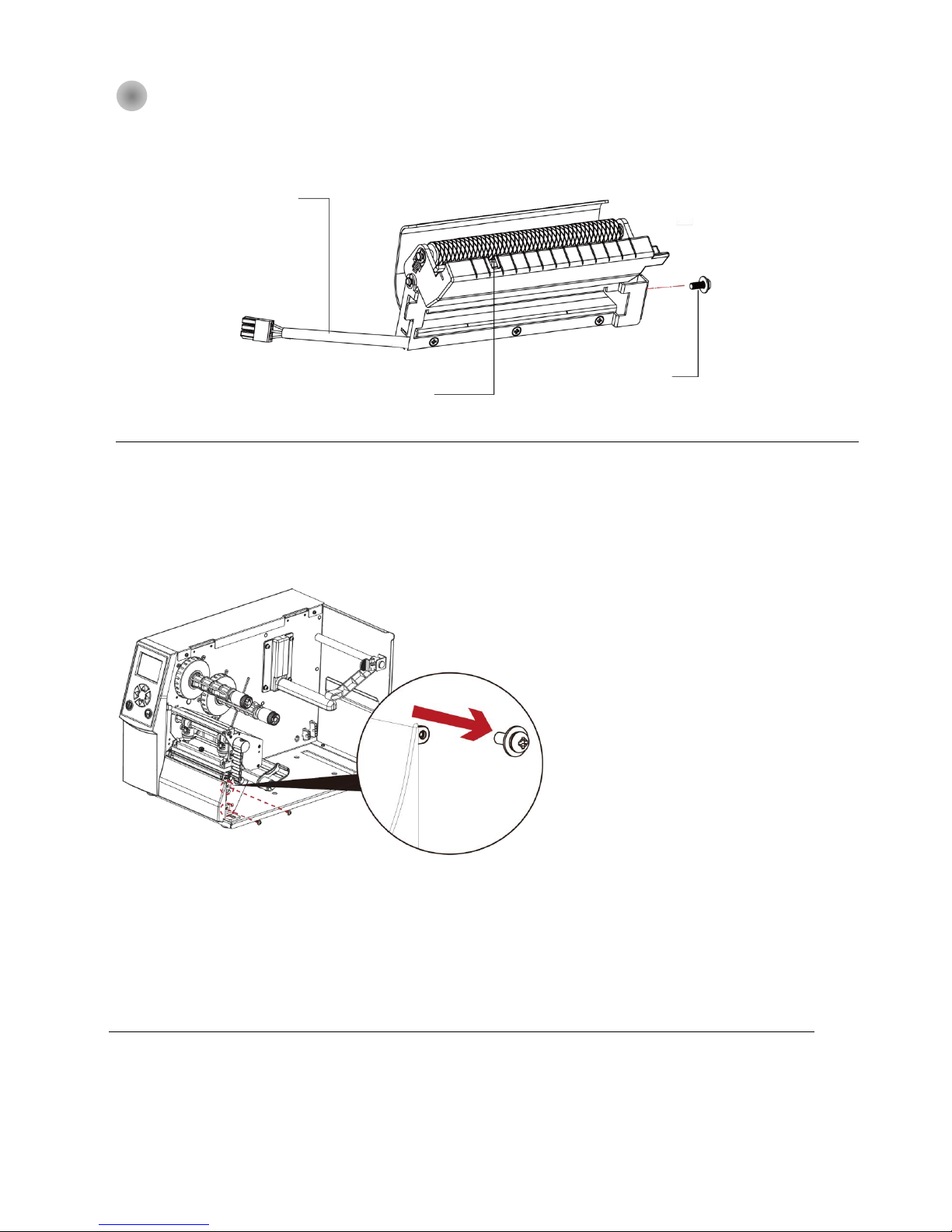
5-3 Installing The Label Dispenser
The Overview of the Label Dispenser
Steps for installing the Label Dispenser:
(Power off the printer and remove the power cable before installing the label dispenser module)
NOTE
* A label liner thickness of 0.006 mm ± 10% and a weight of 65 g/m2 ± 6% are recommended.
** The label dispenser will take labels up to a max. width of 110 mm, and labels should be at least 25 mm high.
*** When using the label dispenser, set the stop position to 9 mm.
CONNECT CABLE OF LABEL
DISPENSER
PAPER SENSOR
SCREWS
1. Remove the screw (as circle indicated).
Page 61
57
2. Remove the cover panel by pushing to
right-hand side.
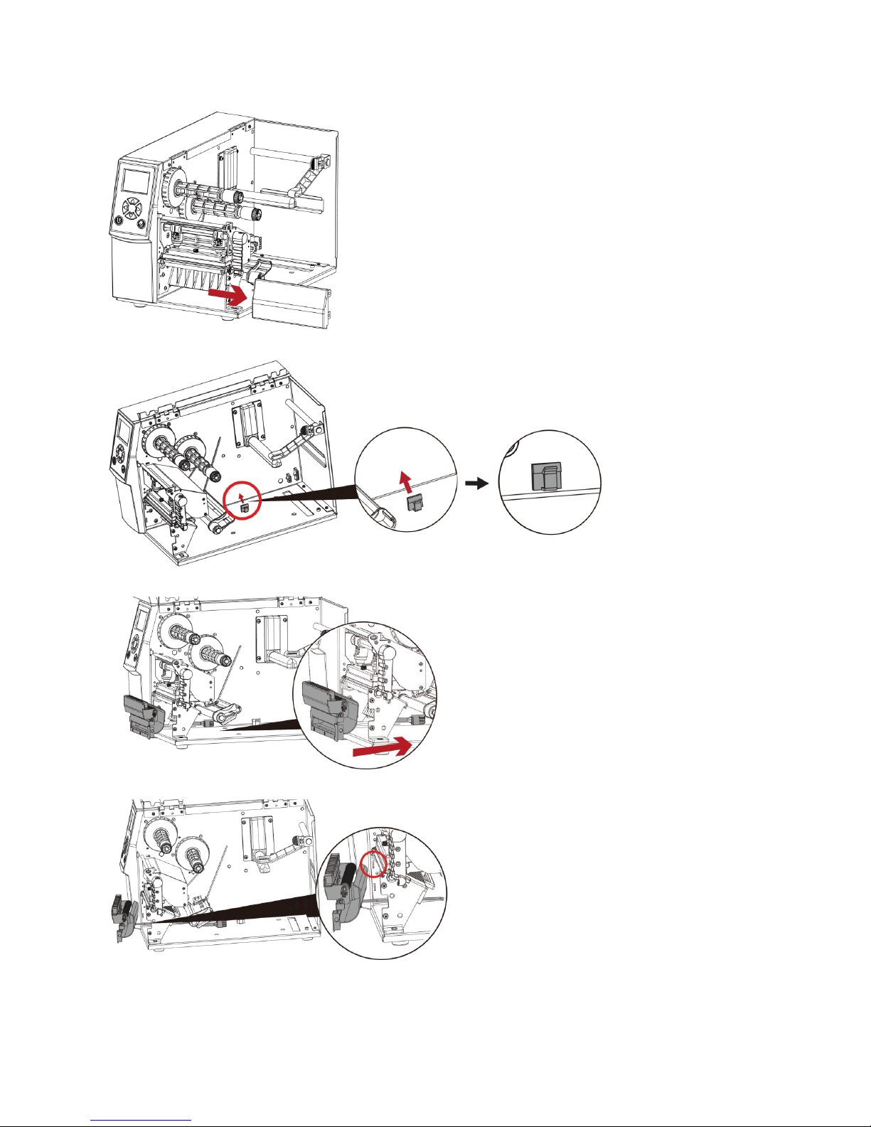
3. Stick the hub onto the circled area.
4. Direct the label dispenser’s cable through the platen
bracket of the printer.
5. Engage the catchs of the label dispenser module
firmly into the printer.
Page 62

58
6. Plug the label dispenser’s cable into the printer in the direction of the arrow.
NOTE
* Printer power should be off when plugging the connector to avoid malfunction
7. Put the cable into the hub.
8. Close printer cover.
Page 63

59
6 Maintenance and Adjustment
6-1 Installing / removing the print head module
NOTE
* Remember to switch off the printer before removing the print head module.
1. Open the printer cover.
2. Using a screwdriver or a
coin, loosen the screw to
take out the TPH module.
3. Turn the print head
counterclockwise
to a top right position
4. Turn the print head
counterclockwise
to a top right position
Page 64

60
6-2 Adjusting the print line
1. Open the printer
cover.
2. Using a screwdriver or a
coin to loosen the screw
3. Turn the print head
counterclockwise
to a top right position
If no improvement is visible, turn the
screws(A) clockwise or counterclockwise
as far as possible and be sure to align with
the indicator board and indicator line.
Repeat the adjustment process until printing
quality has improved.
Page 65

61
6-3 Adjusting ribbon tension
You can adjust the ribbon tension by turning the ribbon shaft knob (see illustration) clockwise or counterclockwise.
There are 4 possible settings, which is marked on the ribbon supply hub.
# 1 : Tension is the highest
# 4 : Tension is the lowest
If the tension is so low that the ribbon does not move forward, you need to reduce the tension of the ribbon supply hub.
To set the tension, press in the knob and turn it clockwise or counterclockwise as required.
Increasing the tension of the ribbon rewind hub will remove any wrinkling of the ribbon during printing,
which results from the use of different ribbon materials. (For details about the wrinkling/creasing of ribbons,
see Section 6-6.)
If you are using a very narrow ribbon, the printer may not move the label stock forward (particularly with
a ribbon that is less than 2" wide). In that case, reduce the tension by turning the knob of the ribbon supply hub
counterclockwise.
Page 66

62
6-4 Cleaning the thermal print head
Dirt on the print head or ribbon may result in inadequate print quality
(there are only partial images on the label). The printer cover should therefore be kept
closed when possible.
Keeping dirt and dust away from the paper or labels ensures a good print quality
and a longer lifespan of the print head. Here is how you clean the print head:
1. Switch off the printer.
2. Open the printer cover.
3. Remove the ribbon.
4. Release the print head by turning the print head release lever.
5. To remove any label residue or other dirt from the print head
(see Red arrow), please use a soft lint-free cloth dipped in alcohol to wipe.
NOTE
* The print head should be cleaned once a week.
** Please make sure that there are no metal fragments or other hard particles on the soft cloth used to clean
the print head.
Page 67

63
6-5 Adjusting the balance and print head tension
1. Open the printer
2. Using a screwdriver or a
coin to loosen the screwcoin to loosen the screw
When using a variety of label stock
and ribbons, the ink may not be evenly distributed.
If there is no printed image on one side of the paper,
or the ribbon wrinkles, the print head pressure
must be readjusted using the TPH spring boxes.
Move the TPH spring boxes as shown in the illustration
to change the print head pressure.
The wider the label you are using, the further apart
the TPH spring boxes must be moved away from
each other. If there is no quality improvement,
you need to change the pressure on the TPH spring boxes.
Turning the screw left increases the pressure,
while turning it right reduces the pressure.
Be sure not to turn the screw so that it goes below Mark(B).
Reset Mark (A)
Mark (B)
Page 68

64
6-6 Ribbon shield settings
The use of different ribbon materials may cause wrinkling of the ribbon, which in turn affects the print result
as illustrated by the examples in (a) and (b). To change the print quality, you can adjust the ribbon shield screws.
If your print result looks like the example in (a), you need to turn ribbon shield screw clockwise.
If your print result looks like the example in (b), you need to turn ribbon shield screw counterclockwise.
NOTE
* If you adjust the screw by more than two full turns, the paper feed may no longer function correctly. In that case,
unscrew the ribbon shield screws to align the reset mark and restart the adjustment process.
To keep track of the change in print quality, you should adjust the screws by half a turn at a time.
Print a test page. If there is no improvement in the print result, turn the screw by another half turn.
Do not turn the adjustment screw more than two full turns(360〫).
Reset Mark
Page 69

65
6-7 Cutter settings
NOTE
* Remember to switch off the printer before removing the CUTTER.
** The label medium should be at least 30 mm long to ensure correct functioning of the cutter.
Switch off the printer before removingthe CUTTER.
(Remove or install cutter refer to ‘’accessories’’ in Section 5)
Unscrew the screw at the
bottom of cutter .
Remove the cutter cover.
Clean and remove jammed paper.
Reinstall CUTTER back onto printer.
Page 70

66
6-8 Troubleshooting
NOTE
* If any problems occur that are not described here, please contact your dealer.
Page 71

67
APPENDIX-PRODUCT SPECIFICATIONS
Model Name
ZX420
ZX420i
ZX430
ZX430i
Print Method
Thermal Transfer / Direct Thermal
Resolution
203 dpi (8 dots/mm)
300 dpi (12 dot/mm)
Print Speed
6 ips (152 mm/s)
4 ips (102 mm/s)
Print Width
4.25” (108mm)
4.16” (105.7mm)
Print Length
Min. 0.16” (4 mm)** ; Max . 157.44” ( 3999mm)
Min. 0.16” (4 mm)** ; Max. 73.19“(1859 mm)
Processor
32-bit RISC CPU
Memory
Flash
128 MB Flash (60 MB for user storage)
SDRAM
32 MB
Sensor Type
Adjustable reflective sensor and transmissive sensor, left aligned
Media
Type
Continuous form, gap labels, black mark sensing, and punched hole; label length set by auto sensing or programming
Width
Tear : Min. 1” (25.4 mm) – Max. 4.64” (118 mm)
Cutter : Max. 4.61” (117 mm)
Dispenser / Rewind : Max. 4.64” (118 mm)
Thickness
Min. 0.003” (0.076 mm) – Max. 0.01” (0.25 mm)
Label roll diameter
Max. 8” (203.2 mm) with 3" (76.2 mm) core
Max. 6” (152.4 mm) with 1.5" (38.1 mm) core
Max. 5" (127 mm) with 1" (25.4 mm) core
Core diameter
Min. 1 " (25.4 mm) – Max. 3" (76.2 mm)
Ribbon
Types
Wax, wax/resin, resin
Length
Max. 1476’ (450 m)
Width
Min. 1.18” (30 mm) – Max. 4.33” (110 mm)
Ribbon roll diameter
3” (76.2 mm)
Core diameter
1” (25.4 mm)
Printer
Language
EZPL, GEPL, GZPL auto switch
Software
Label design
software
GoLabel (for EZPL only)
Driver
Windows 2000, XP, Vista, Windows 7, 8.1 and 10 , Windows Server 2003 & 2008、 MAC、 Linux
DLL
Win CE, .NET, Andriod, Windows Mobile, Windows 2000 / XP / VISTA / 7 / 8.1 / 10
Resident
Fonts
Bitmap Fonts
6, 8, 10, 12, 14, 18, 24, 30, 16X26 and OCR A & B
Bitmap fonts 90°, 180°, 270° rotatable, single characters 90°, 180°, 270° rotatable
Bitmap fonts 8 times expandable in horizontal and vertical directions
TTF Fonts
TTF Fonts (Bold / Italic / Underline ). 0°,90°, 180°, 270° rotatable
Download
Fonts
Bitmap Fonts
90°, 180°, 270° rotatable, single characters 90°, 180°, 270° rotatable
Asian Fonts
16x16, 24x24. Traditional Chinese (BIG-5), Simplified Chinese(GB2312), Japanese (S-JIS), Korean (KS-X1001)
90°, 180°, 270° rotatable and 8 times expandable in horizontal and vertical directions
TTF Fonts
TTF Fonts (Bold / Italic / Underline ). 0°,90°, 180°, 270° rotatable
Barcodes
1-D Bar Codes
China Postal Code, Codabar, Code 11, Code 32,Code 39, Code 93, Code 128 (subset A, B, C), EAN-8, EAN-13, EAN 8/13 (with 2 & 5 digits
extension), EAN 128, FIM, German Post Code, GS1 DataBar, HIBC, Industrial 2 of 5 , Interleaved 2-of-5 (I 2 of 5), Interleaved 2- o-f 5 with
Shipping Bearer Bars, ISBT – 128, ITF 14, Japanese Postnet, Logmars, MSI, Postnet, Plessey, Planet 11 & 13 digit, RPS 128, Random Weight,
Standard 2 of 5, Telepen, UPC-A, UPC-E, UPC-A and UPC-E with EAN 2 or 5 digit extension, UCC 128, UCC/EAN-128 K-Mart
2-D Bar Codes
Aztec code, Code 49,Codablock F , Datamatrix code, MaxiCode, Micro PDF417, Micro QR code, PDF417,QR code, TLC 39
Code Pages
Codepage 437, 737,850, 851, 852, 855, 857, 860, 861, 862, 863, 865, 866, 869,
Windows 1250, 1251, 1252, 1253, 1254, 1255, 1257
Unicode UTF8、UTF16BE、UTF16LE
Graphics
Resident graphic file types are BMP and PCX, other graphic formats are downloadable from the software
Interfaces
• USB 2.0 (B-Type)
• USB 2.0 (B-Type)
• Serial port: RS-232 (DB-9)
• IEEE 802.3 10/100 Base-Tx Ethernet
port
(RJ-45)
• USB Host (A-Type)
• USB 2.0 (B-Type)
• USB 2.0 (B-Type)
• Serial port: RS-232 (DB-9)
• IEEE 802.3 10/100 Base-Tx
Ethernet port (RJ-45)
• USB Host (A-Type)
Control Panel
•1 Power on/standby button
with green color LED backlight
• 1 Calibration button at rear
panel
• 1 Control key : FEED /
PAUSE / CANCEL with dual
color LED backlight: Ready
(Green); Error (Red)
• Color TFT LCD with navigation
button
•1 Power on/standby button with green
color LED backlight
• 1 Calibration button at rear panel
• 1 Control key : FEED / PAUSE /
CANCEL with dual color LED backlight:
Ready (Green); Error (Red)
•1 Power on/standby
button with green color
LED backlight
• 1 Calibration button at
rear panel
• 1 Control key : FEED
/ PAUSE / CANCEL with
dual color LED backlight:
Ready (Green); Error
(Red)
• Color TFT LCD with navigation
button
•1 Power on/standby button with
green color LED backlight
• 1 Calibration button at rear panel
• 1 Control key : FEED / PAUSE /
CANCEL with dual color LED
backlight: Ready (Green); Error
(Red)
RTC
Standard
Power
Auto Switching 100-240V AC, 50-60Hz
Environment
Operation
temperature
41°F to 104°F (5°C to 40°C)
Storage temperature
-4°F to 140°F (-20°C to 60°C)
Humidity
Operation
20-85%, non-condensing
Storage
10-90%, non-condensing
Agency Approvals
CE (EMC)、FCC Class B、CB、UL、cUL、CCC
Dimension
Length
15.86” (403 mm)
Height
10.79” (274 mm)
Width
10.24” (260 mm)
Weight
23.81lbs (10.8 Kg), excluding consumables
Options
Cutter (Dealer Install)
Parallel port adaptor module (Centronic female 36-pin)(Dealer Install)
Bluetooth (Dealer Installer)
Wireless LAN (IEEE 802.11 b/g/n) (Dealer Install)
External label rewinder
Label Dispenser (Dealer Install)
* Specifications are subject to change without notice. All company and/or product names are trademarks and/or registered trademarks of their respective owners.
** Minimum print height and maximum print speed specification compliance can be dependent on non-standard material variables such as label type, thickness, spacing, liner
construction, etc. GoDEX is pleased to test non-standard materials for minimum print height, and maximum print speed capability.
Page 72

68
APPENDIX- INTERFACE
Page 73

Step 7.
Step 6.
Step 8.
Step 2. Step 3.
1
2
ZX400(i)/BPZ400(i) Series 無線網路安裝說明
ZX400(i)/BPZ400(i) Series Wi-Fi Module Installation
Step 1.
1
Step 4.
Step 5.
2
1
2
1
2
2
Wi-Fi
BT
Wi-Fi
1
Page 74

Step 7.
Step 6.
Step 8.
Step 2.
Step 3.
1
2
ZX400(i)/BPZ400(i) Series 藍牙模組安裝說明
ZX400(i)/BPZ400(i) Series BlueTooth Module Installation
Step 1.
1
2
Step 4.
Step 5.
1
2
1
1
2
2
BT
BT
Wi-Fi
Page 75

Step 7.
Step 6.
Step 8.
Step 2.
Step 3.
ZX400(i)/BPZ400(i) Series 並列傳輸模組安裝說明
ZX400(i)/BPZ400(i) Series Parallel module Installation
Step 1.
Step 4.
Step 5.
2
1
1
2
2
1
1
2
2
1
Page 76

GoDEX Printer Compliance Insert
Note: This equipment may be used on an IT power system.
For Users in English Speaking Regions (en)
Caution: This marking indicates that the user should read all included documentation before use.
The users of this product are cautioned to use accessories and peripherals approved by GoDEX International Co.,Ltd. The use of
accessories other than those recommended, or changes to this product that are not approved by GoDEX International Co.,Ltd. ,
may void the compliance of this product and may result in the loss of the user’s authority to operate the equipment.
Caution: For power supply, use GoDEX provided. No user-serviceable parts.
FCC Digital Emissions Compliance
This equipment has been tested and found to comply with the limits for a CLASS A digital device,
pursuant to Part 15 of the FCC Rules. These limits are designed to provide reasonable protection
against harmful interference when the equipment is operated in a commercial environment. This
equipment generates, uses, and can radiate radio frequency energy and, if not installed and used
in accordance with the instructions, may cause harmful interference to radio communications.
Operation of this equipment in a residential area is likely to cause harmful interference in which case
the user will be required to correct the interference at own expense.
Canadian Digital Apparatus Compliance
This Class A digital apparatus meets all requirements of the Canadian Interference-Causing Equipment Regulations
CE Marking: Refer to the Declaration of Conformity for a list of the EU Directives and Standards that this product complies with.
Für Anwender in Deutschland (de)
Vorsicht: Diese Kennzeichnung weist darauf hin, dass der Benutzer vor dem Gebrauch alle mitgelieferten Unterlagen lesen soll.
Die Benutzer dieses Produkts werden darauf hingewiesen, nur Zubehörteile und Peripheriegerä te zu verwenden,
die von GoDEX International Co.,Ltd. genehmigt sind. Falls nicht empfohlene Zubehö rteile verwendet oder an diesem Produkt Ä nderungen
vorgenommen werden, die nicht von GoDEX International Co.,Ltd. genehmigt sind, kann dadurch die behördliche Konformitä t des Produkts
verletzt werden und der Benutzer die Berechtigung zur Verwendung des Gerä ts verlieren.
Vorsicht:
Nur das
beigefügte original
GoDEX
Netzteil verwenden. Enthä lt
keine Teile, die vom
Benutzer gewartet werden
können.
CE-Kennzeichnung: Die Konformitä tserklä rung enthä lt eine Liste der EU-Richtlinien und Normen, denen das Produkt entspricht.
Warnhinweis
Dies ist ein Produkt der Klasse A. In Wohnumgebungen kann dieses Produkt Funkstörungen verursachen.
In diesem Fall obliegt es dem Anwender, angemessene Maßnahmen zu ergreifen.
Pour les utilisateurs canadiens et franç ais (fr)
Attention: Ce marquage indique que l’usager doit, avant l’utilisation, lire toute la documentation incluse.
Attention: Pour la source d'alimentation, utilisez GoDEX International Co.,Ltd. Il ne contient aucune pièce réparable par l’utilisateur.
Utilisateurs de ce produit sont avisés d’utiliser des accessoires et des périphé riques approuvés par GoDEX International Co.,Ltd.
L’utilisation d’accessoires autres que ceux recommandé s ou des changements à ce produit qui ne sont pas approuvés
par GoDEX International Co.,Ltd. peuvent annuler la conformité de ce produit et mettre fin au droit qu’a l’usager d’utiliser l’équipement.
Conformité aux normes canadiennes sur les appareils numériques
Cet appareil numé rique de la classe A respecte toutes les exigences du Réglement sur le maté riel brouilleur du Canada.
AVERTISEMENT: Il s’agit d’un produit de classe A. Dans un environnement domestique, ce produit pourra provoquer des interférences
radio auquel cas l’utilisateur pourrait avoir à prendre de mesures adé quates.
適用於臺灣使用者(zh-tw)
注意:此標誌表示使用者應在使用前先閱讀所有隨附的文件。
本產品的使用者必須小心使用科誠股份有限公司許可的配件與週邊設備。 使用非上述建議的配件,或是在未經科誠股份有限公司許
可的情況下變更本產品可能會使得本產品的相容性失效,並且使得使用者 喪失操作設備的權力。
請使用科誠股份有限公司電源。無使用者可自行維修之零件。
www.godexintl.com
GoDEX International
Co.,Ltd.
313-043200-101
사용자안내문
이 기기는 업무용 환경에서 사용할 목적으로 적합성평가를 받은 기기로서
가정용 환경에서 사용하는 경우 전파간섭의 우려가 있습니다
 Loading...