

Page 1
Rev. A, 03.2010
User’s Manual
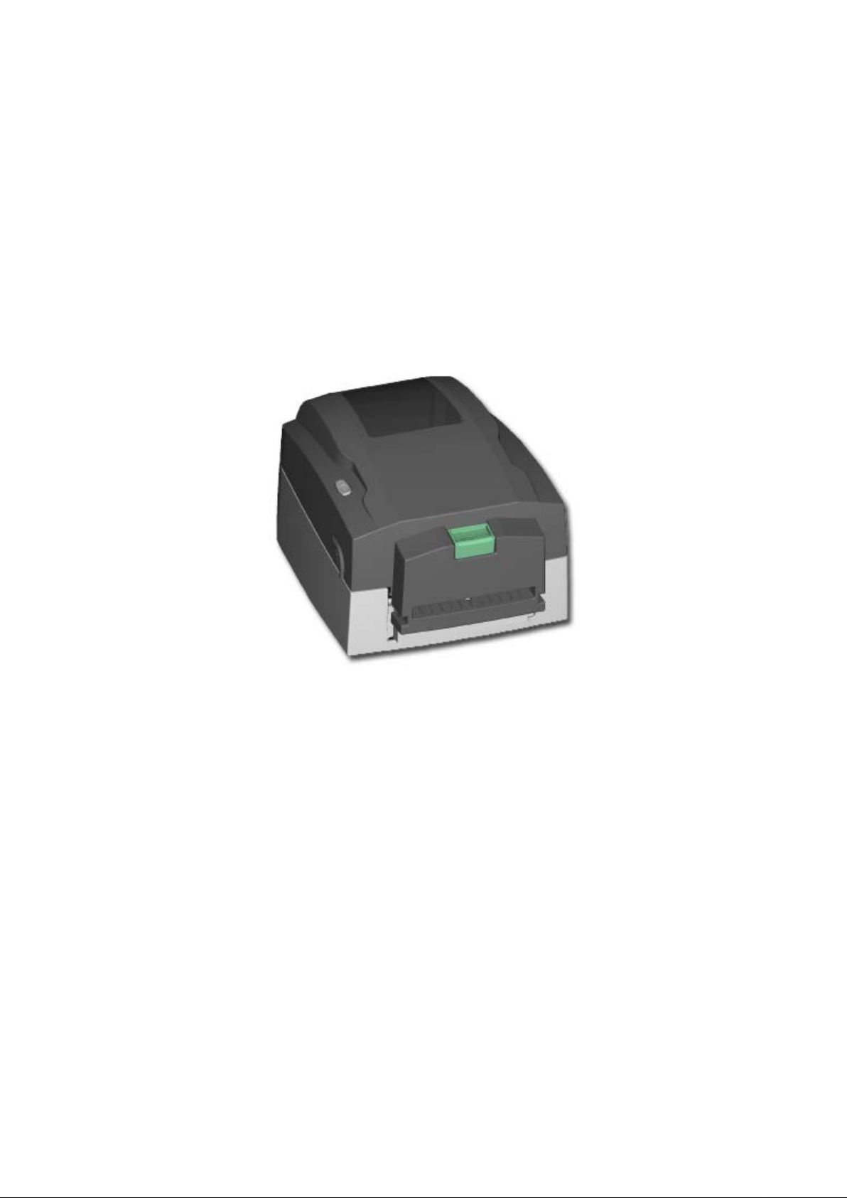
DuraLabel 4000
Page 2

1
FCC COMPLIANCE STATEMENT
FOR AMERICAN USERS
This equipment has been tested and found to comply wit h the limits for a CLAS S A digital device,
pursuant to Part 15 of the FCC Rules. These limits are designed to provide reasonable
protection against harmful interference when the equipment is operated in a commercial
environment. This equipment generates, uses, and can radiate radio frequency energy and, if
not installed and used in accordance with the instructions, may cause harmful interference to
radio communications. Operation of this equipment i n a residential area is likely to cau se harmful
interference in which case the user will be requi red to correct the interference at own expense .
CAUTION
Danger of explosion if battery is incorrectl y replaced
Replace only with the equivalent type recommen ded by the manufacture.
Dispose of used batteries according to the manufacturer’s instructions.
Only use with power supply adapter model: WDS060240
Changes or modifications not expressly approved by the party responsible for compliance could
void the user's authority to operate the equi pm ent.
Specifications are subject to change without notice.
DuraLabel 4000 User’s Manual
Page 3

2
Safety Instructions
Please read the following instructions seriously.
1. Keep the equipment away from humidity.
2. Before you connect the equipment to the power outlet, please check the voltage of the
power source.
3. Disconnect the equipment from the voltage of the power source to prevent possible
transient over voltage damage.
4. Don’t pour any liquid to the equipment to avoid electrical shock.
5. ONLY qualified service personnel for safety reason should open equipment.
6. Don’t repair or adjust energized equipment alone under any circumstances. Someone
capable of providing first aid must always be present for your safety
7. Always obtain first aid or medical attention i m m edi ately after an injury. Never neglect
an injury, no matter how slight it seems.
DuraLabel 4000 User’s Manual
Page 4

3
1. BARCODE PRINTER ................................................................... 4
1-1. Printer Accessories ......................................................................................................... 4
1-2. General Specifications
1-3. Communication Interface
1-4. Printer Parts
2. MEDIA INSTALLATION ............................................................. 10
2-1. Label Installation ........................................................................................................... 10
2-2. Ribbon Installation
2-3. Switch the Label Roll Core
2-4. PC Connection
2-5. Driver Installation
3. PRINTER SETTING ................................................................... 18
3-1. FEED Key ..................................................................................................................... 18
3-2. LED Status
3-3. Auto Sensing
3-4. Self-Test page
3-5. Error Messages
4. ELECTRONIC GUILLOTINE CUTTER INSTALLATION ........... 21
.................................................................................................... 4
................................................................................................ 6
.................................................................................................................... 7
........................................................................................................ 12
............................................................................................ 14
.............................................................................................................. 15
.......................................................................................................... 16
.................................................................................................................... 18
................................................................................................................. 18
............................................................................................................... 19
............................................................................................................. 20
5. MAINTENANCE AND ADJUSTMENT
5-1. Thermal Print Head Cleaning ....................................................................................... 23
5-2. Thermal Print Head Balance Adjustment
5-3. Print Line Adjustment
5-4. Clean the Manual Cutter Module
5-5. Clean the Electronic Guillotine Cutt er
5-6. Troubleshooting
....................................... 23
...................................................................... 23
.................................................................................................... 24
.................................................................................. 24
........................................................................... 26
............................................................................................................ 28
DuraLabel 4000 User’s Manual
Page 5
4
1. Barcode Printer
Model
DuraLabel 4000
Print Method
Thermal Transfer / Direct Thermal
Resolution
203 dpi (8 dot/mm)
Print Speed
2 IPS (50 mm/s)
Print Width
4.25” (108 mm)
Print Length
Min. 1.18” (30 mm); Max. 68” (1727 mm)
Memory
4MB Flash (2MB for user storage) ; 8MB SDRAM
Sensor Type
Fixed transmissive sensor and reflective sensor.
Types: Continuous form, gap labels, black mar k sensing, and punched hole;
Core diameter: 1”, 1.5” (25.4 mm, 38.1 mm)
Types: Wax, wax/resin, resin
Core diameter: 0.5” (12.7 mm)
Printer Language
EZPL
Software
Driver & DLL: Windows 2000, XP and Vista
Bitmap fonts: 6, 8, 10, 12, 14, 18, 24, 30, 16X26 and OCR A & B
Scalable fonts 90°, 180°, 270° rotatable
Bitmap fonts 90°, 180°, 270° rotatable, single characters 90°, 180°, 270°
Asian fonts 90°, 180°, 270° rotatable and 8 t im es expandable in horizontal and
Scalable fonts 90°, 180°, 270° rotatable
1-D Bar codes:
128, UPC A / E (add on 2 & 5), I 2 of 5, I 2 of 5 with S hip ping Bea re r
Bars, EAN 8 / 13 (add on 2 & 5), Codabar, Post NET, EAN 128, DUN 14, HIBC,
and GS1 DataBar
2-D Bar codes:
PDF417, Datamatrix code, MaxiCode, QR code and Micro QR code
1-1. Printer Accessories
After unpacking, please check the accessories that come with the package, and store
appropriately.
Barcode printer
Power cord
Switching Power
USB Cable
Empty Ribbon Roll
Label Roll Core
Label Stop Plate
Quick Start Guide
CD (includes Windows Driver and Manuals)
1-2. General Specifications
Media
Ribbon
Resident Fonts
Download Fonts
label length set by auto sensing or programming
Width: 1” (25.4 mm) Min. - 4.64” (118 mm) Max.
Thickness: 0.003” (0.06 mm) Min. - 0.01” (0.2 5 mm) Max.
Label roll diameter: Max. 5” (127 mm)
Length: 360’ (110 m)
Width: 1.18” Min - 4.33” (30 mm - 110 mm) Max
Ribbon roll diameter.: 1.57“ (40 mm)
Bitmap fonts 90°, 180°, 270° rotatable, single characters 90°, 180°, 270°
rotatable
Bitmap fonts 8 times expandable in horizontal and v ertical directions
rotatable
vertical directions
Code 39, Code 93, Code 128 (subset A, B, C), UCC/EAN-128 K-Mart,
UCC/EAN-
Barcodes
DuraLabel 4000 User’s Manual
MSI (1 Mod 10), Random Weight, Telepen, FIM , China Postal Code, RPS 128
Page 6
5
CODEPAGE 437, 850, 851, 852, 855, 857, 860, 861, 862, 863, 865, 866, 869,
Unicode (UTF8, UTF16)
Resident graphic file types are BMP and PCX, other graphic formats are
downloadable from the software
Interfaces
USB port
One Tri-color LED: Power (Green, Orange and Red)
Control key: FEED
Power
Auto Switching 100-240VAC, 50-60Hz
Operation temperature: 41°F to 104°F (5°C t o 40°C)
Storage temperature: -4°F to 122°F (-20°C to 50°C)
Operation: 30-85%, non-condensing.
Storage: 10-90%, non-condensing.
Agency
Approvals
Length: 10” (254 mm)
Width: 8.8” (224 mm)
RFID Detection (HF 13.56MHz / ISO 15693 sta ndard)
trademarks and/or registered trademarks of their respective owners.
Code Pages
Graphics
Control Panel
Environment
Humidity
Dimension
Weight
Functionality
Options
Specifications are subject to change without notice. All company and/or product names are
737
WINDOWS 1250, 1251, 1252, 1253, 125 4, 1255
FCC Class A, CB, cUL
Height: 6.7” (170 mm)
5.5 lbs (2.5Kg) ,excluding consumables
Standard Manual Guillotine Cutter
Electronic Guillotine Cutter
DuraLabel 4000 User’s Manual
Page 7
6
1-3. Communication Interface
9600 baud rate、no parity、8 data bits、1 stop bit、XON/XOFF protocol
PC
PRINTER
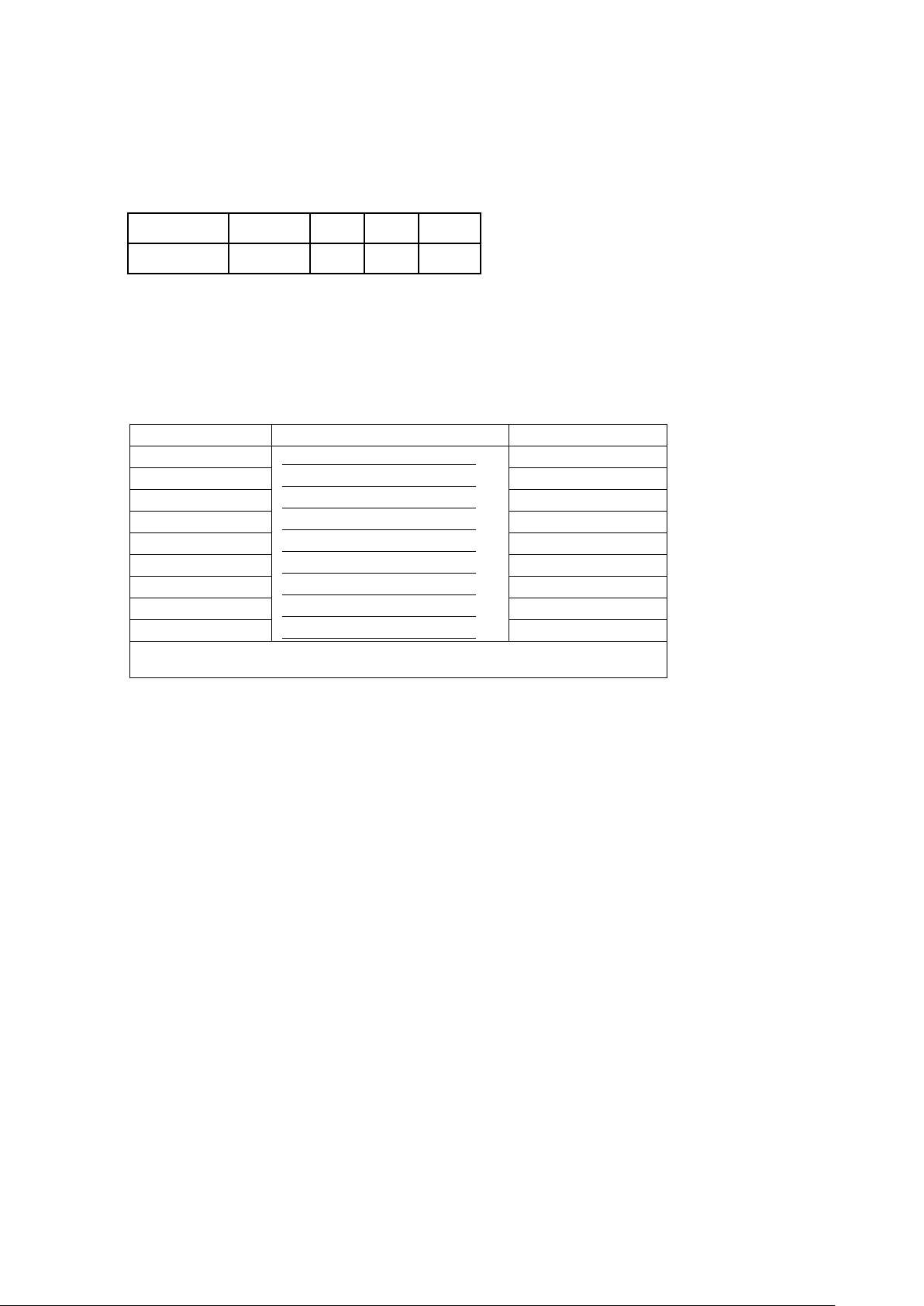
USB Interface
Connector Type : Type B
PIN NO. 1 2 3 4
FUNCTION VBUS D- D+ GND
Serial Interface (Optional)
Serial Default
Setting
RS232 HOUSING (9-pin to 9-pin)
DB9 SOCKET DB9 PLUG
--- 1 1 +5V,max 500mA
RXD 2 2 TXD
TXD 3 3 RXD
DTR 4 4 N/C
GND 5 5 GND
DSR 6 6 RTS
RTS 7 7 CTS
CTS 8 8 RTS
RI 9 9 N/C
:
and RTS/CTS。
【
Note】
The total current output from parallel port and serial port altogether can not exceed 500mA.
DuraLabel 4000 User’s Manual
Page 8
7
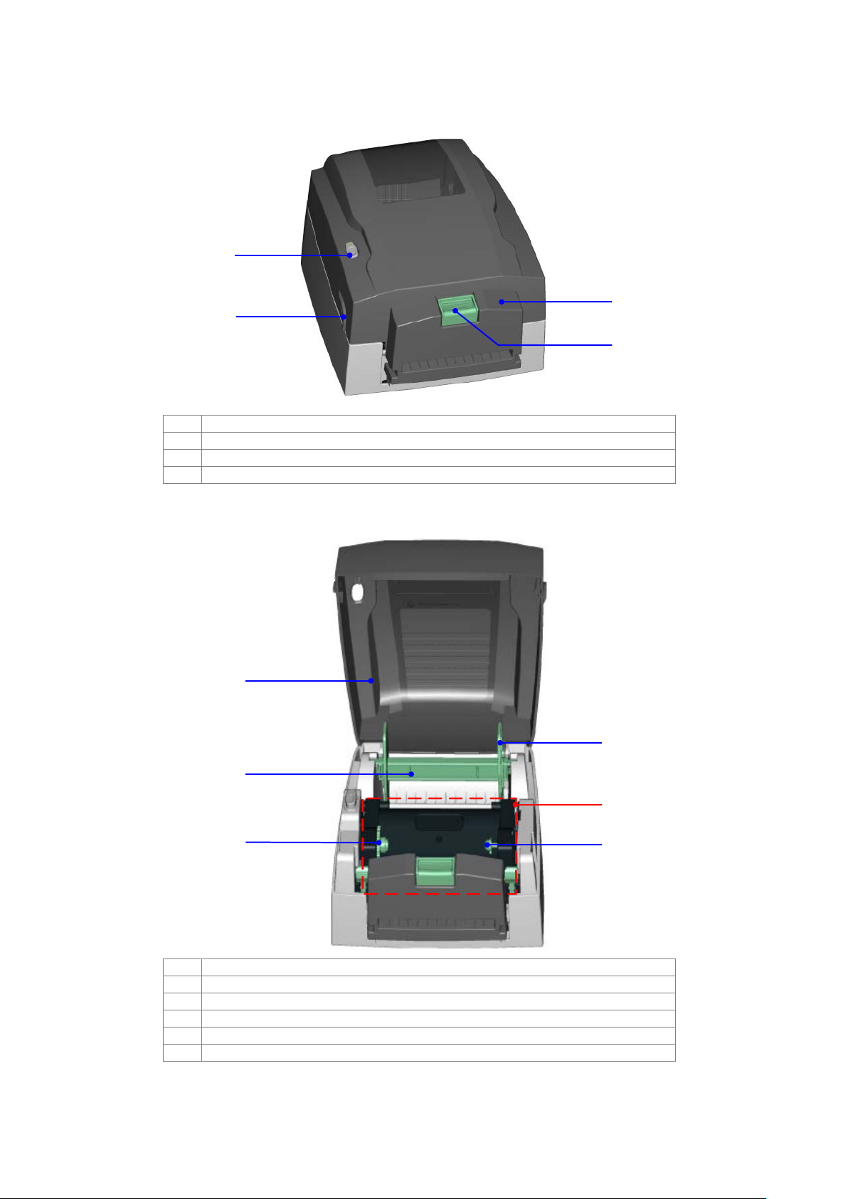
1-4. Printer Parts
1
2
3
4
1.
FEED Key and LED Light
2.
Cover Open Button
3.
Manual Cutter Module
4.
Manual Cutting Button
1
2
3
5
6
4
1.
Top Cover
2.
Label Roll Core
3.
Ribbon Rewind Wheel
4.
Label Roll Stop Plate
5.
Print Mechanism
6.
Ribbon Core Holder (rewind)
DuraLabel 4000 User’s Manual
Page 9
8
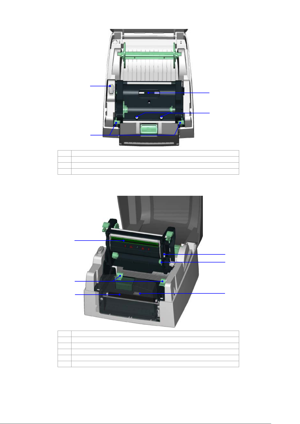
1
3
4
2
1.
LED Light
2.
Locking Tenon (left/right)
3.
Ribbon Observing Window
4.
Print Head Pressure Adjustment Screw (lef t/right)
4
6
3
2
1
5
1.
Thermal Print Head
2.
Label Guide
3.
Platen Roller
4.
Print Line Adjustment Gear
5.
Ribbon Core Holder (supply)
6.
Label Sensor
DuraLabel 4000 User’s Manual
Page 10

9
1
2
4
3
1.
Fan-Fold Label Insert
2.
Power Switch
3.
Power Socket
4.
USB Port
DuraLabel 4000 User’s Manual
Page 11

10
2. Media Installation
Thermal
Transfer (TT)
When printing, ribbon must be installed to transf er the print contents onto the
label.
Direct Thermal
(DT)
When printing, no ribbon is necessary; it only requires direct thermal label.
1. Open the top cover by pressing
2. Place the label roll onto the Label
3. Press the locking tenons and then
DuraLabel 4000 has capability to print in both Thermal Transfer mode and Direct Thermal mode.
It also supports RFID tag reading function that can detect the type of label used for printing. To
ensure the best quality of printout, please use t he designated label for printing.
【
Note】The printer will stop the printing procedure when a non -designated label has been
detected to be used for printing.
The general descriptions of Thermal Transfer mode and Direct Thermal mode are as follows:
Please check which print mode you will use and then go into the Setting Mode to change the
print mode setting if necessary.
2-1. Label Installation
the Cover Open Buttons on both
sides.
Roll Core and then assemble the
Label Stop Plate on both sides.
lift up the Printing Mechanism.
DuraLabel 4000 User’s Manual
Page 12

11
4. Feed the label through the
Manual Cutter Module.
6. Close the Printing Mechanism
1
2
7. Pressing the Manual Cutting
5. Align the Label Guides to the
edge of label.
【
Note】
When adjusting the Label Guides,
please move both Label Guides
together at the same time.
and the top cover to complete the
label installation.
Button to cut the label in anytime
when you need.
DuraLabel 4000 User’s Manual
Page 13

12
2-2. Ribbon Installation
1. Open the top cover by pressing
2. Install the rewind ribbon roll from
3. Press the locking tenons and then
4. Place a new ribbon roll from the
the Cover Open Buttons on both
sides.
the right side of printer and then
fix it on left side.
lift up the Printing Mechanism.
right side of printer and then fix it
on left side.
【
Note】
Please align the Ribbon Supply Wheel
with the fillister of ribbon roll core when
installing the ribbon roll. You can rotate
the black gear as figure showed to help
to align the ribbon roll core.
DuraLabel 4000 User’s Manual
Page 14

13
5. Feed the ribbon from the Ribbon
Supply Shaft.
8. Close the Printing Mechanism
1
2
6. Wrap the ribbon around the
Printing Mechanism and stick the
ribbon onto the rewind ribbon roll.
7. Rotate the Ribbon Rewind Wheel
to make the ribbon tight and
smooth.
and the top cover to complete the
installation.
DuraLabel 4000 User’s Manual
Page 15

14
2-3. Switch the Label Roll Core
(A) 1” roll core installation
(B) 1.5” roll core installation
DuraLabel 4000 User’s Manual
Page 16

15
2-4. PC Connection
1. Please make sure the printer is powered off .
2. Plug the power cable into the power socket on the wa l l , and then connect the other end of
the cable to printer's power socket.
3. Connect the cable to the USB port on the printer and on the PC.
4. Turn on the PC and the printer, and then the printer’s LED light will shine.
【
Note】
Please make sure the power switch is off before pl ugging the power cable into the printer.
DuraLabel 4000 User’s Manual
Page 17

16
2-5. Driver Installation
1. Insert the product CD to your
6. Select connection port.
computer’s CD Drive and find
the "Windows Drives" folder.
2. Select the icon of driver file and
click it to start the installation.
3. Follow the instruction on screen
to keep the installation going.
Then the Driver Wizard utilit y
should run automatically.
4. Select "Install printer drivers".
5. Select printer model.
DuraLabel 4000 User’s Manual
Page 18

17
7. Enter the printer name and set
printer sharing option.
8. A description page of printer
11. After the driver installation is
settings will be displayed after
all settings are completed.
9. Check if all printer settings are
correct and then press Finish to
start copying driver files.
10. Wait for file copying finished
and complete the installation.
complete, there should be a
new printer model on Windows
"Printer and Faxes" setting.
DuraLabel 4000 User’s Manual
Page 19

18
3. Printer Setting
Press and hold the FEED Key then power on the printer.
Printers are currently in Auto
please refer to page 19.
3-1. FEED Key
After pressing the FEED key, printer will feed the media (accordi ng to media type) to the
specified stop position. When printing with continuou s media, pressing the FEED key will feed
the media out to a certain length. When printing with labels, the printer will feed one label each
time the FEED key is pressed. If the label is not sent out in a correct position, please proceed
with the Auto Sensing (see next section).
3-2. LED Status
Press and hold the FEED key then power on the printer. Wait for the LED light flashing red and
then release the FEED key, the printer will enter i nto Auto Sensing Mode to do the calibration. A
Self-Test page will be printed out automatically after the calibration is completed. Below are the
sequence and the description of two modes:
LED Light Status
Green
Red (Flash)
Standby Mode
Auto Sensing Mode
Normal status
Sensing Mode. The calibration will
be performed and a Self-Test page
will be printed out to show the
configurations of printer. For more
detail about Auto Sensing Mode,
please refer to next section. For the
descriptions of Self-Test page
Description
3-3. Auto Sensing
Printer can automatically detect the label and store the res ul t of detecting. By doing this, the
printer will calibrate the printing position of the l abel and the user can do printing without setting
the label length. To perform the Auto Sensing, please do as follows:
1. Check if the label is correctly loaded on the printer.
2. Power off the printer, press and hold the FEED key.
3. Power on the printer while still holding the FEE D key. Keep holding the FEED key, wait for
the LED light turn to flash red and then release the FEED key. P rinter will automatically
detect the label and record it.
4. A Self-Test page will be printed out after Auto Sensing is completed and the printer goes
back to standby mode.
DuraLabel 4000 User’s Manual
Page 20

19
3-4. Self-Test page
DuraLabel 4000 : VX.XXX
Model & Version
The Self-Test page helps user to figure out whether the printer is operating normally. Below are
some general descriptions about the content of Self-Test page:
【
For more information about advance settings, such as "Print mode switch", "Sensor switch" or
"Dump Mode", please refer to Programmer's manual.
Serial port setup
USB port setting
Test pattern
Number of DRAM installed
Image buffer size
Number of forms
Number of graphics
Number of fonts
Number of Asian fonts
Number of Databases
Number of Scalable fonts
Free memory size
Speed, Density, Ref. Point, Print direction
Label width, Form length
Cutter, Stripper, Mode
Sensor Setting
Sensor Setting
Code Page
Note】
Serial port :96,N,8,1
int-usb sw setting: ext-USB
1 DRAM installed
Image buffer size : 1500K
000 FORM(S) IN MEMORY
000 GRAPHIC (S) IN MEMORY
000 FONT(S) IN MEMORY
000 ASIAN FONT(S) IN MEMORY
000 DATABASE(S) IN MEMORY
000 TTF(S) IN MEMORY
2048K BYTES FREE MEMORY
^S4 ^H10 ^R000 ~R200
^W10 ^Q48,3
Option : ^D0 ^O0 ^AD
Reflective Sensor Value: 42_48
Voltage: 1.50 2.30 3.10(1.6_0.8)
Code Page: 850
DuraLabel 4000 User’s Manual
Page 21

20
3-5. Error Messages
Replace with new label roll or ribbon
roll.
Possible causes: card tags or paper fall
adjust it according to actual usage.
1. Please install the ribbon if you want to
Thermal media.
Memory is full; printer will
print out “Memory full.”
Delete unnecessary data in the
memory.
File name is duplicated;
“Filename is repeated.”
Wait for the print head temperature
stop flashing.
When an error happened during print ing process, dif ferent LED light mes sages wi ll be dis played.
Users can diagnose the error situation according to the LED light.
Frequency
Color
Quickly blinking
Red light
Slowly blinking
Orange light
LED Light Description Solution
Media Error
Unable to detect the media.
Media Out
Please perform the Auto Sensing again.
into the gap behind the platen roller,
Print Mode
Error
Door Open
Media Jam
Ribbon is not installed when
in Thermal Transfer mode.
Printing Mechanism is not
firmly closed.
can’t find label gap/black mark, black
mark paper out or ribbon out. Please
print in Thermal Transfer mode.
2. Or change the print mode to Direct
Thermal mode and print with Direct
Re-open the Printing Mechanism and
make sure it closes tightly.
Steady
Can’t find the file; printer
Error
Memory
will print out “Filename
can not be found.”
printer will print out
Print head
Error
The temperature of print
head is too high.
Use “~X4” command to print out all the
files, and then check whether the file
exist and the file name is correct.
Change the file name and download
again.
drops to the normal temperature range,
and then printer will go back to the
standby mode and the LED light will
DuraLabel 4000 User’s Manual
Page 22

21
4. Electronic Guillotine Cutter Installation
Electronic Guillotine Cutter
Module
1
2
Module Screw (TAP 3*8) x
2pcs
30mm in height.
1. Open the top cover by
1
2
【
Note1】
Please power off the printer
before installing the cutter
module.
【
Note2】
The label / paper that used for
cutting is suggested to be at least
pressing the Cover Open
Buttons on both sides.
2. Loosen and then lift the
printing mechanism up by
pressing the Locking
Tenons.
3. Unscrews the screws of
Manual Cutter Module.
4. Unplug the sensor connector
of Manual Cutter Module
and then remove the
module.
DuraLabel 4000 User’s Manual
Page 23

22
5. Flip the Electronic Guillotine
Cutter Module downward.
6. Plug the connector of Cutter
7. Place the cutter module into
1
2
Connection Wire into the
socket on the printer.
【
Note】
Before plugging the connector
into socket, please check the pin
first.
the printer from left side of
the module first, and then fit
it to the right side.
8. Tighten the Module Screws
and then flip the cutter
module upward.
9. Close the Printing
Mechanism and the top
cover to complete the
installation.
【
Note】
It is not suggested to use
label-inside paper when printing
with cutter module.
DuraLabel 4000 User’s Manual
Page 24

23
5. Maintenance and Adjustment
Unclear printouts may be caused by
necessary to keep the top cover closed.
arrow) there’s label pieces or other
industrial use alcohol to wipe away
or hard particles attached on it.
When printing with different label
materials or using different ribbon ty pes,
printing quality or damage on printer.
+
-
+
-
5-1. Thermal Print Head Cleaning
dusty print head, ribbon stain or label
liner glue. Therefore when printing, it’s
Also, check and prevent paper/label
from being stained or dusty to ensure
print quality and to prolong the print
head life. Print head cleaning
instructions are as follows:
1. Power-off the printer.
2. Open the top cover.
3. Take out the ribbon.
4. Open the print head by pressing
the locking tenons.
5. If on the print head (see blue
stain, please use a soft cloth with
the stain.
【
Note1】
Weekly cleaning on the print head is
recommended.
【
Note2】
When cleaning the print head with soft
cloth, make sure there is no any metal
5-2. Thermal Print Head Balance Adjustment
unbalanced print quality may occur due
to the media material differences, thus
it’s necessary to adjust the Thermal
Print Head pressure.
1. Open the top cover.
2. Take out the ribbon.
3. Turn the print head adjustment
screws slightly by screwdri ver to
increase (turn to "+") or decrease
(turn to "-") print head pressure.
【
Note】
Please turn the adjustment screws
carefully since it may cause worse
DuraLabel 4000 User’s Manual
Page 25

24
5-3. Print Line Adjustment
To get better printing balance and
A
B
1
2
1. Unscrew the screws on both
2. Unplug the Sensor Connector.
3. Unscrew the Cutter Cover Screw
quality, use print head adjusting gear
to adjust the contacting surface
between print head and label.
1. When turning print head
adjusting gear counter-clockwise
(as arrow 1 shows), print line
would move in the direction
where arrow A shows.
2. When turning print head
adjusting gear clockwise (as
arrow 2 shows), print line would
move in the direction where
arrow B shows.
5-4. Clean the Manual Cutter Module
sides of the cutter module.
【
Note】
Please power off the printer before
cleaning the cutter module.
from the bottom of the module.
DuraLabel 4000 User’s Manual
Page 26

25
4. Remove the cover by the
6. After cleaning the back sides of
7. Turn the cutter and clean the
direction shown in figure.
5. Use the cotton swab and alcohol
to wipe both upper and lower
blades.
blades, press down and hold the
cutter as shown in figure.
blade with cotton swab and
alcohol from other side.
8. Reassemble the cutter module
after cleaning is completed.
DuraLabel 4000 User’s Manual
Page 27

26
5-5. Clean the Electronic Guillotine Cutter
1. Unscrew the screws on both
2. Unplug the Connector of
4. Remove the front cover as
5. Before doing the cleaning,
sides of the cutter module.
【
Note】
Please power off the printer
before cleaning the cutter module.
Cutter Connection Wire.
3. Unscrew the cover screws
on both sides of module.
shown in figure.
you can use screw driver to
adjust the blades upward or
downward if needed.
DuraLabel 4000 User’s Manual
Page 28

27
6. Turn the screw driver
clockwise, the blade will
7. Clean the blade with cotton
move downward; turn the
screw driver
counter-clockwise, the blade
will move upward.
swab and alcohol.
8. Reassemble the cutter
module after cleaning is
completed.
DuraLabel 4000 User’s Manual
Page 29

28
5-6. Troubleshooting
Power on the printer, but the
LED does not light up
LED light turns red
♦ Check for software setting or program command errors
When printing, label is
Head, please remove it by using soft cloth wit h al cohol.
Check if power supply is correct
When printing, part of the label
Check the media quality
Printout not in desired position
Check if liner is suitable for use, please contact reseller for
Check if label roll edge is aligned with Label Width Guide
When printing, page skipping
Unclear printout
♦ Check print darkness setting
Check if Thermal Print Head is covered with glue or s tain
When using cutter, label
cutting occurs
Problem Recommended Solution
♦ Check the power connector
(power/status) after printing
stops
Printing started, but nothing
was printed on the label
jammed/tangled up
When printing, only part of the
contents were printed
wasn’t printed completely
occurs
♦ Replace with suitable label or ribbon
♦ Check if label or ribbon is all out
♦ Check if label is jammed/tangled up
♦ Check if mechanism is not closed(Thermal P ri nt Head not
positioned correctly)
♦ Check if sensor is blocked by paper/label
♦ Check if label is placed upside down or if label i s not
suitable for the application
♦ Select the correct printer driver
♦ Select the correct label and print type
♦ Clean the label jam, and if label is stuck on The rmal Print
♦ Check if label or ribbon is stuck on the Thermal Print Head
♦ Check if application software has errors
♦ Check if start position setting has errors
♦ Check if ribbon has wrinkles
♦ Check if ribbon supply shaft is creating frict i on with the
platen roller. If the platen roller needs to be replaced,
please contact your reseller for more information
♦
♦ Check if Thermal Print Head is stained or dusted
♦ Use internal command “~T” to check Thermal Print Head
can print completely
♦
♦ Check if sensor is covered by paper or dust
♦
more information
♦
♦ Check if error occurs on label height sett ing
♦ Check if the sensor is covered by dust
♦
♦ Check if cutter is installed properly
couldn’t feed or abnormal
【
Note】
Your dealer is knowledgeable about printers, printing software, and your unique system.
Please contact your local dealer for further techni cal support .
DuraLabel 4000 User’s Manual
♦ Check if Paper Feed Rods are sticky
 Loading...