


246138
globalindustrial.ca
User's manual Manual del usuario Manuel de l'utilisateur
Customer Service
US: 1-800-645-2986
Servicio de atención al Cliente
US: 1-800-645-2986
Service à la clientèle
Canada: 888-645-2986
Models
Ultrasonic Humidifier
246135
246136
246137
246138
246139
O.D. = 43/4"
I.D. = 49/16"
8
7
6
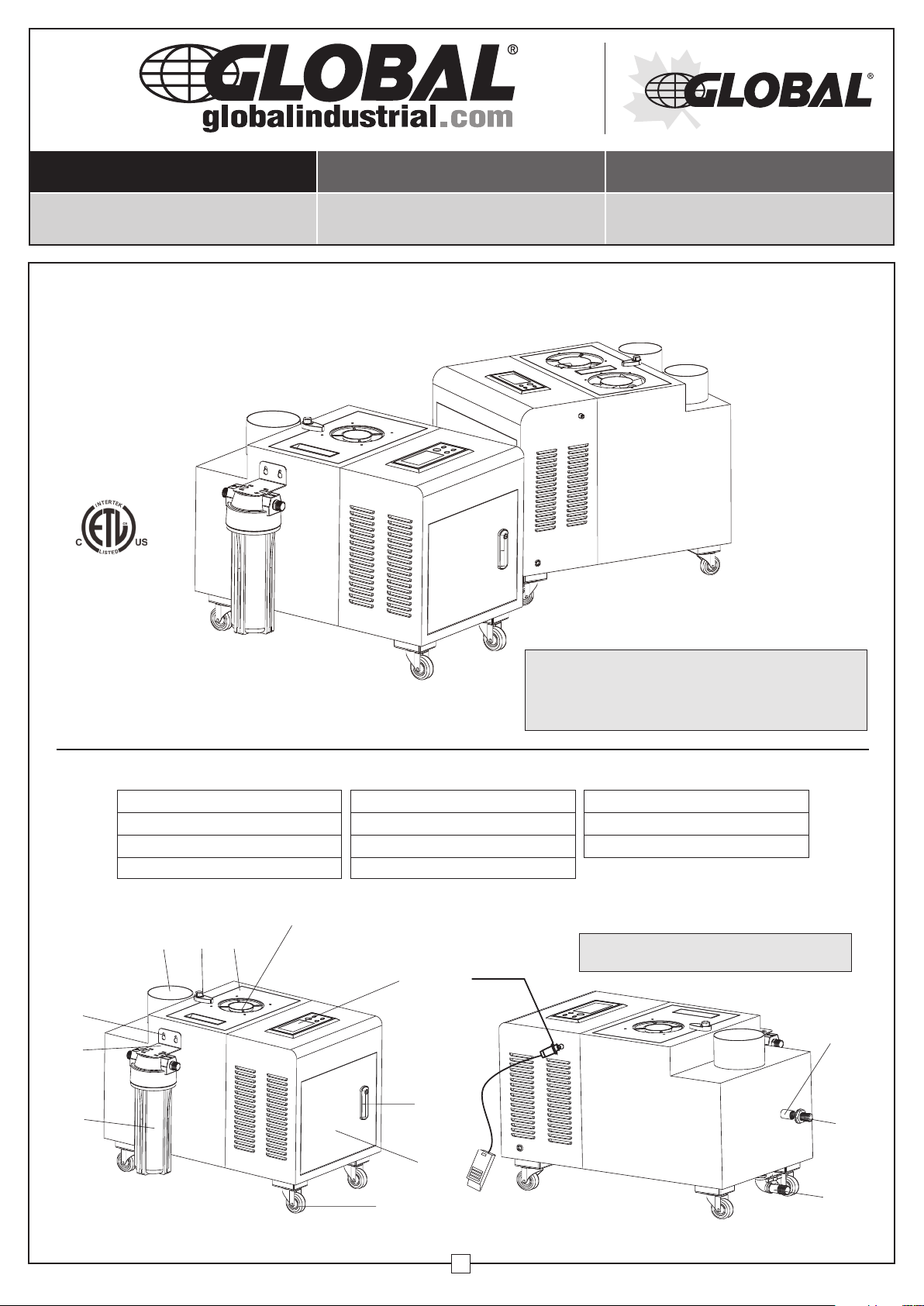
1. Control Panel
2. Door Lock
3. Electrical Panel (Behind Door)
4. Wheels
9 10
11
This manual will provide you with information concerning
operation, maintenance, and troubleshooting your
humidifier. Following the instructions will ensure the
1 Year Limited Warranty
proper function and extended lifespan of your unit.
PRODUCT COMPONENT IDENTIFICATION
5. Electrical Panel Air Inlet
6. Pre-Sediment Filter
7. Mounting Bracket
8. Bracket Mounting Hole
5
Humidity sensor
1
2
connection
9. Spray Outlet
10. Tank Cover
11. Fix Screw
Note: Ensure drain valve is in the closed position
unless outlet drain pipe is being utilized.
Overflow
Inlet
3
Figure 1 Figure 2
4
1
Outlet
050120
User Guide
Ultrasonic Humidifier
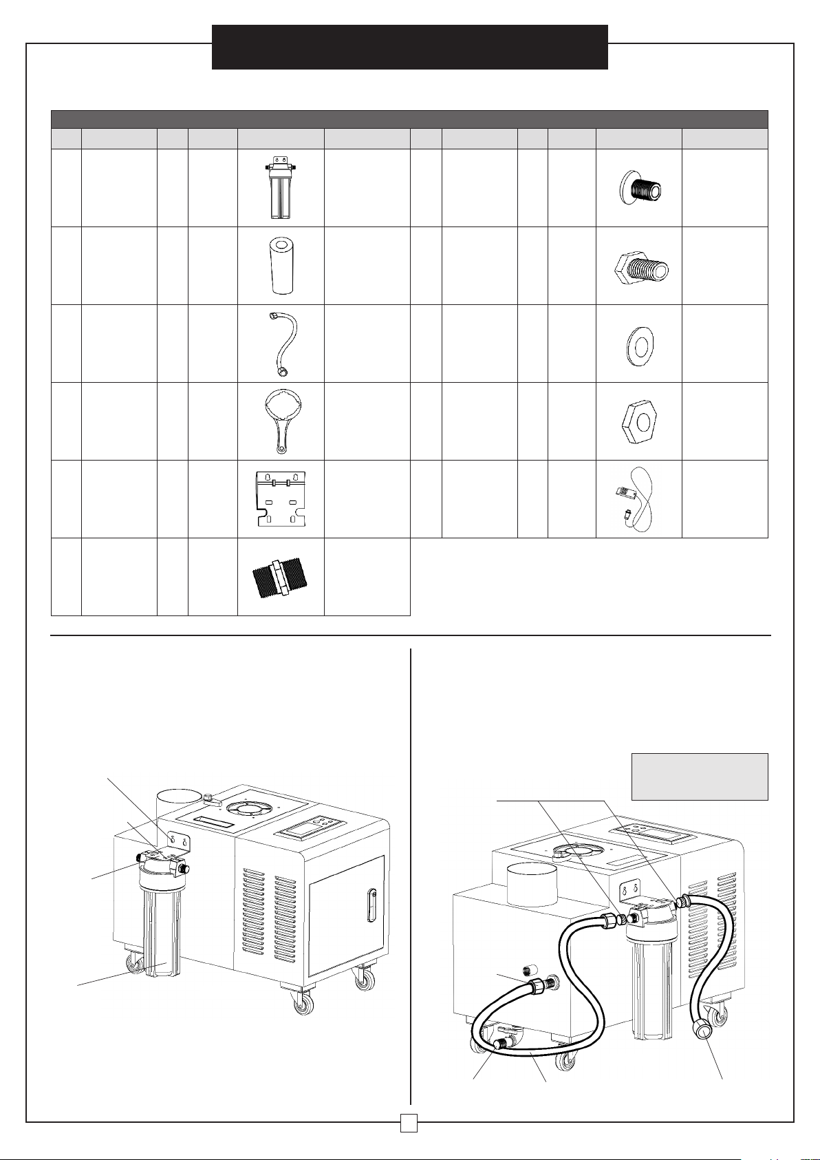
ASSEMBLY
CONTENTS
Ref. Description Qty. Spec. Image Note Ref. Description Qty. Spec. Image Note
H1
H2 Filter Element 2 PP
H3
H4 Spanner 1 ---
H5
H6
Filter 1 --- See Figure 3
Connecting
Hose
Mounting
Bracket
Hose
Connector
11
2
19
1 ---
Outer
Dia.
2
DN15
(1/4")
/16"
H7
Place filter
element into
filter. Second
one is a
replacement
See Figure 4 H9 Flat Washer 8 Ø12* 6 See Figure 3
Used to loosen
cover of filter
container to
clean filter.
See Figure 10
Fixed on the
side panel.
See Figure 3
See Figure 4
H8 Screw 2 M6* 16 See Figure 3
H10 Nut 2 M6 See Figure 3
H11
Screw 4 ST4* 16 See Figure 3
Humidity
Sensor
1 32' See Figure 2
Filter Installation
Install water filter using the mounting bracket as illustrated
in Figure 3. The filter enables the humidifier's water
system to run smoothly, and prevents water impurities
from flowing into the unit blocking the solenoid valve
and clogging the system.
(H8) Screw
(H10) Nut
(H7) Screw
(H9) Washer
Bracket
Filter
1. Filter Bracket
• Attach bracket to the pre-drilled holes located on the
side of the unit.
• Using the four supplied screws, attach the filter
underneath the bracket (Figure 3).
Figure 3
2. Filter Connections
• Attach hose connectors onto ends of each hose.
• Hose A: Connect one end to the filter and the other end
to the water inlet port on the unit (Figure 4).
• Hose B: Connect one end to the filter and the other
end to the fresh water supply.
Note: The height of the
connector hose A cannot
1/4" Hose
Connectors
Water
Inlet
Water Outlet
To Drain
Connector
Hose A
be higher than the outlet.
Figure 4
Connector Hose B
To Tap Water Supply
2
Ultrasonic Humidifier
User Guide
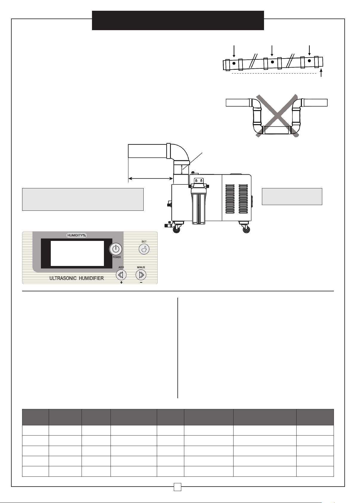
PIPE LAYOUT
For optimum performance, install the pipeline according
to the requirements in the owners manual. Seal all pipe
connections so there are no air or water leaks.
• Insert water pipe directly into spray outlet. Clamps are
not included.
• To prevent water running back into the unit, the spray outlet
holes must be pointing upwards at a minimum of 30 degrees.
• The diameter of the spray outlet holes must be 9/16".
• The distance between the spray outlet holes should be
between 31/4" and 8".
•
The height at the end of the pipe needs to be higher than the
humidifying section, 1/8" rise per foot (Figure 5).
• DO NOT connect the water pipe with a "trap" as shown in
Figure 6.
Water Pipe
≤ 77/8"
Note: To avoid machine water damage, outlet pipe
connections should be no shorter than 6" before an
elbow connection. (See Fig 7)
≤ 6"
Spray Outlet Spray Outlet Spray Outlet
Figure 5
Figure 6
Note: Water outlet pipe is
sold separately
End of pipe 1/8"
rise per foot
OPERATION
POWER: Press "POWER" button to start or stop unit.
HUMIDITY: Pres "+" or "-" buttons to adjust humidity
between 30-90% range.
TIMER: Press "SET" button then "+" or "-" buttons to
set timer range between 1 to 24 hours.
SYSTEM FUNCTION
Humidity Control: Connect the humidity sensor (H11) to
the humidifier by screwing the connection directly into
the side of the unit (see Figure 2). This sensor is 32 ft.
long and is used in areas where users need to control
the humidity level. The sensor measures the Relative
Humidity (RH%) data which will be shown on the LED
display. The user can set a target humidity percentage
on the control panel (see HUMIDITY OPERATION steps
above); when that humidity set point is reached, the unit
will stop automatically. When the humidity in the area
rises above the set point, unit function will resume. The
humidity range is 30-90%. The unit will stop at +5% of
set humidity and restart below -5% of set humidity.
Low Water Level Warning: When the system detects
the water level is lower than the warning level, the unit
will stop automatically. The system will warn if water is
not refilled within 10 minutes.
Fan Delay Protection: When the humidifier is turned
off, the fan will continue to run for an additional 30
seconds to drain the residual water and cool the unit.
Water Inlet: When the water level in the water tank
decreases, the float switch will activate and the water
tank will refill automatically and stop filling when the
water level rises to the maximum height. The "FULL"
hole is just the overflow point if the water has exceeded
the maximum height. Leave this hole as it is and don't
connect any hose to it. Only when the float switch is
broken, the tank won't stop filling water automatically
and then water will overflow from this point.
Figure 7
TECHNICAL PARAMETERS
Model
246135 110V/60Hz 190W 80 Auto 411/32 Single Outlet 235/8 x 1325/32 x 183/16 40
Power
Supply
Power
(watts)
Spray Capacity
(pints per day)
Control
Manner
Spray Outlet
Diameter"
Size" Weight (lbs.)
246136 110V/60Hz 240W 150 Auto 411/32 Single Outlet 235/8 x 1325/32 x 183/16 40
246137 110V/60Hz 450W 300 Auto 411/32 Single Outlet 235/8 x 1325/32 x 183/16 41
246138 110V/60Hz 730W 450 Auto 411/32 Double Outlet 2425/32 x 187/64 x 221/8 63
246139 110V/60Hz 950W 600 Auto 411/32 Double Outlet 2425/32 x 187/64 x 221/8 66
3
Ultrasonic Humidifier
TROUBLESHOOTING
Problem Possible Causes Solution
No power Check the circuit and recover power supply
Indicator is off
The supply tank
is not filling
with water
Automation
indicator is on but
there is no spray
No water supply from the pipe Check water supply valve
Water inlet solenoid valve is damaged Replace solenoid valve
Main control board is damaged Replace main control board
Inlet water pressure is not enough Inlet water pressure shall be 5 Kg
Voltage is 5% less than required voltage Check the voltage
Blown fuse Replace fuse of same specification
Power switch is off Turn on power switch
User Guide
Water leaking
out of unit
Reduced or
no spay
Foreign matter in the solenoid valve Dismantle the solenoid valve to clear foreign matter
Scale in the water box Clear the water box
Voltage is too low Maintain normal voltage
No water in the water tank Add water to the water tank
ERROR CODES
Code Description
E1 or E2 Humidity Sensor Failure
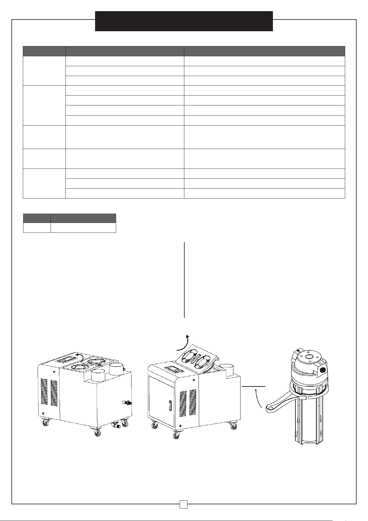
MAINTENANCE
Maintenance of the water tank
Water should be changed regularly, once every 7 days.
The automatic computer flushing system helps to
minimize dirt and residue in the water tank.
Clean the water tank
The water tank should be cleaned regularly, once every
30 days. Please remove the electrical plug from the
wall socket before changing the water tank to avoid
electric shock.
Cleaning Method
1. Remove all water from the water tank, using the water
outlet (See figure 4).
2. Open the top cover and remove the tank cover. Use
a soft cloth or brush to clean in and around the water
tank. Wash out with clean water.
3. Water should not be spilled on the external components
and wires to prevent short circuit.
4. Do not use detergent to clean any components
of atomizer.
5. Re-install the cover.
Figure 8 Figure 9
Clean the filter
The filter should be cleaned regularly, at least once a month.
1. Unscrew the cover of the filter.
2. Clear the dirt on the filter element.
3. Re-install the cover.
Loose
Figure 10
4
 Loading...