


 Loading...
MVBAYAI
Intel® Atom® processor motherboard
User's Manual
Rev. 1001

Copyright
© 2014 GIGA-BYTE TECHNOLOGY CO., LTD. All rights reserved.
The trademarks mentioned in this manual are legally registered to their respective owners.
Disclaimer
Information in this manual is protected by copyright laws and is the property of GIGABYTE. Changes to the specifications and features in this manual may be made by GIGABYTE without prior notice. No part of this manual may be reproduced, copied, translated, transmitted, or published in any form or by any means without GIGABYTE's prior written permission.
Documentation Classifications
In order to assist in the use of this product, GIGABYTE provides the following types of documentations:
For detailed product information, carefully read the User's Manual.
For product-related information, check on our website at:
http://www.gigabyte.com

Table of Contents
Box Contents.................................................................................................................... |
|
|
4 |
MVBAYAI Motherboard Layout......................................................................................... |
5 |
||
Block Diagram.................................................................................................................. |
|
8 |
|
Chapter 1 Hardware Installation...................................................................................... |
9 |
||
1-1 |
Installation Precautions..................................................................................... |
9 |
|
1-2 |
Product Specifications.................................................................................... |
10 |
|
1-3 |
Installing the Memory...................................................................................... |
12 |
|
|
1-3-1 |
Installing a Memory ................................................................................................ |
12 |
1-4 |
Back Panel Connectors.................................................................................. |
13 |
|
1-5 |
Internal Connectors........................................................................................ |
15 |
|
Chapter 2 BIOS Setup................................................................................................... |
30 |
||
2-1 |
The Main Menu............................................................................................... |
32 |
|
2-2 |
Advanced Menu.............................................................................................. |
34 |
|
|
2-2-1 |
Hardware Monitor ................................................................................................... |
35 |
|
2-2-2 S5 RTC Wake Settings........................................................................................... |
36 |
|
|
2-2-3 |
CPU Configuration.................................................................................................. |
37 |
|
2-2-3-1 |
CPU Information...................................................................................................... |
38 |
|
2-2-4 |
SATA Configuration................................................................................................. |
39 |
|
2-2-5 |
CSM Configuration.................................................................................................. |
40 |
|
2-2-6 |
SIO Configuration.................................................................................................... |
41 |
2-3 |
Chipset Menu.................................................................................................. |
46 |
|
2-4 |
Security Menu................................................................................................. |
47 |
|
|
2-4-1 |
Secure Boot menu.................................................................................................. |
48 |
|
2-4-1-1 |
Key Management.................................................................................................... |
49 |
2-5 |
Boot Menu...................................................................................................... |
51 |
|
2-6 Save & Exit Menu........................................................................................... |
52 |
||
- 3 -
Box Contents
Motherboard
IO Shield *1 (12AIO-MVBAY0-00R)
SATA 2.0 cable 500mm*1 (25CF4-500522-H3S)
SATA power cable *1 (25CRI-100B00-H3R)
•The box contents above are for reference only and the actual items shall depend on the product package you obtain. The box contents are subject to change without notice.
•The motherboard image is for reference only.
- 4 -
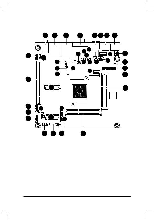
MVBAYAI Motherboard Layout |
|
|
|
|
|
|
||||
|
1 |
2 |
3 |
4 |
|
|
5 |
6 |
7 |
8 |
28 |
|
|
|
34 |
41 40 |
|
|
39 |
9 |
|
29 |
|
|
|
42 |
|
|
38 |
|
||
|
30 |
|
|
35 |
36 |
37 |
|
10 |
||
|
|
|
|
|
||||||
|
|
31 |
|
33 |
|
43 |
|
|
|
11 |
|
|
32 |
|
|
|
|
|
|
12 |
|
27 |
|
|
|
|
|
|
|
|
||
|
|
|
|
|
|
|
|
|
|
|
26 |
14 |
13 |
|
|
25 |
24 |
|
16 |
23 |
|
||
|
19 |
|
|
22 |
|
17 |
21 |
20 |
18 |
15 |
- 5 -

Item |
Code |
Description |
|
1 |
AUDIO |
Audio connectors |
|
2 |
USB_LAN1 |
RJ45 LAN port (top) / USB 2.0 ports |
|
(buttom) |
|||
|
|
||
3 |
USB_LAN2 |
RJ45 LAN port (top) / USB 2.0 ports |
|
|
(buttom) |
||
|
|
||
4 |
VGA_COM2 |
Serial port (top) / VGA port (bottom) |
|
5 |
HDMI |
HDMI port |
|
6 |
KB_MS |
PS/2 Mouse/Keyboard cable connector |
|
7 |
RUSB1 |
USB 3.0 port |
|
8 |
DC_IN |
DC In power connector |
|
9 |
ATX_12V |
4 pin main power connector |
|
10 |
JRS6 |
LVDS enable/disable jumper |
|
11 |
LVDS |
LVDS connector |
|
12 |
BKL_CN |
LCD Inverter Connector |
|
13 |
SODIMM1 |
DDR3 SO-DIMM slot |
|
14 |
CPU |
CPU |
|
15 |
SODIMM2 |
DDR3 SO-DIMM slot |
|
16 |
COM5 |
Serial port cable connector #5 |
|
17 |
COM6 |
Serial port cable connector #6 |
|
18 |
SATAPW_1 |
SATA HDD power connector |
|
19 |
M_SATA |
mSATA/extension board connector |
|
20 |
SATA1 |
SATA 3Gb/s connector |
|
21 |
F_PANEL |
Front panel header |
|
22 |
LPC |
LPC connector |
|
23 |
F_USB1 |
USB 2.0 header |
|
24 |
AT_CN |
AT/ATX Power Mode Select jumper |
|
25 |
GPIO_CNT |
GPIO connector |
|
26 |
MIN_PCIE |
Mini PCi Express connector |
|
27 |
PCI |
PCI 32bit/33MHz slot |
|
28 |
F_AUDIO |
Front Panel Audio connector |
|
29 |
SKP_OUT |
Audio Amplifier connector |
|
30 |
CPU_FAN |
CPU fan connector |
|
31 |
BAT_CN |
Battery cable connector |
|
32 |
CLR_CMOS |
Clear CMOS jumper |
|
33 |
SYS_FAN |
Systen fan connector |
|
34 |
JCOM3 |
COM3 Power Select jumper |
|
35 |
COM3 |
Serial port cable connector #3 |
|
36 |
COM4 |
Serial port cable connector #4 |
|
37 |
COM1 |
Serial port cable connector #1 |
|
38 |
JCOM1 |
COM1 Power Select jumper |
|
39 |
JRS3 |
RS232/RS422/RS485 Select Jumper for |
|
COM1 |
|||
|
|
- 6 -

40 |
JRS2 |
RS232/RS422/RS485 Select Jumper for |
|
COM1 |
|||
|
|
||
41 |
JRS4 |
RS232/RS422/RS485 Select Jumper for |
|
COM1 |
|||
|
|
||
42 |
JRS1 |
RS232/RS422/RS485 Select Jumper for |
|
COM1 |
|||
|
|
||
43 |
JP2 |
LVDS Panel GPIO Control jumper |
- 7 -
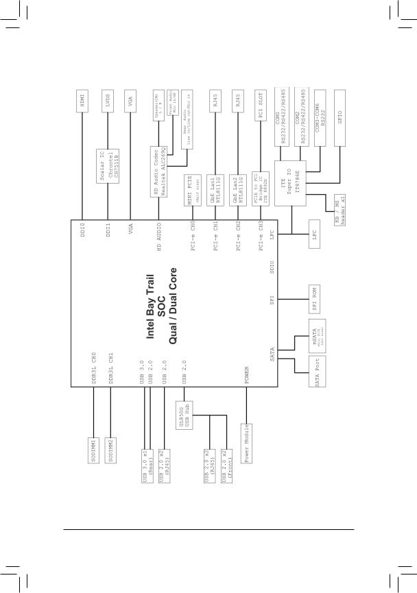
Block Diagram
- 8 -

Chapter 1 Hardware Installation
1-1 Installation Precautions
The motherboard contains numerous delicate electronic circuits and components which can become damaged as a result of electrostatic discharge (ESD). Prior to installation, carefully read the user's manual and follow these procedures:
•Prior to installation, do not remove or break motherboard S/N (Serial Number) sticker or warranty sticker provided by your dealer. These stickers are required for warranty validation.
•Always remove the AC power by unplugging the power cord from the power outlet before installing or removing the motherboard or other hardware components.
•When connecting hardware components to the internal connectors on the motherboard, make sure they are connected tightly and securely.
•When handling the motherboard, avoid touching any metal leads or connectors.
•It is best to wear an electrostatic discharge (ESD) wrist strap when handling electronic components such as a motherboard, CPU or memory. If you do not have an ESD wrist strap, keep your hands dry and first touch a metal object to eliminate static electricity.
•Prior to installing the motherboard, please have it on top of an antistatic pad or within an electrostatic shielding container.
•Before unplugging the power supply cable from the motherboard, make sure the power supply has been turned off.
•Before turning on the power, make sure the power supply voltage has been set according to the local voltage standard.
•Before using the product, please verify that all cables and power connectors of your hardware components are connected.
•To prevent damage to the motherboard, do not allow screws to come in contact with the motherboard circuit or its components.
•Make sure there are no leftover screws or metal components placed on the motherboard or within the computer casing.
•Do not place the computer system on an uneven surface.
•Do not place the computer system in a high-temperature environment.
•Turning on the computer power during the installation process can lead to damage to system components as well as physical harm to the user.
•If you are uncertain about any installation steps or have a problem related to the use of the product, please consult a certified computer technician.
- 9 - |
Hardware Installation |
1-2 |
Product Specifications |
||
|
|
|
|
|
CPU |
|
Support for Intel® Celeron® J1900 (2.0 GHz) processor |
|
|
|
TDP 10W |
|
|
|
L1/L2 cache varies with CPU |
|
Memory |
|
2 x SO-DIMM slots support 1.35V DDR3L 1333/1600MHz |
|
|
|
Support up 16GB |
|
Audio |
|
Realtek® ALC269 codec |
|
|
|
High Definition Audio |
|
|
|
2 channel |
|
LAN |
|
2 x Realtek RTL8111G GbE controllers supports 10/100/1000 Mbps |
|
|
|
|
|
Expansion Slots |
|
1 x mini PCI 32bit/33MHz slot |
|
|
|
1 x Mini PCI Express slot (full size) |
|
Onboard |
|
Build in Intel® Intel® processor |
|
Graphics |
|
|
|
Storage Interface |
1 x SATA 3Gb/s connector |
|
|
|
|
1 x mSATA socket (full size) |
|
USB |
|
Up to 6 USB 2.0 ports (4 on the back panel, 2 via the USB brackets connected |
|
|
|
to the internal USB headers) |
|
|
|
1 x USB 3.0 port |
|
Internal |
|
1 x 4 pin ATX 12V power connector |
|
Connectors |
|
1 x SATA 3Gb/s connector |
|
|
|
1 x SATA Power connector |
|
|
|
1 x CPU fan header |
|
|
|
1 x System fan header |
|
|
|
5 x Serial port cable connectors |
|
|
|
2 x COM power select headers (JCOM1/JCOM3) |
|
|
|
1 x Front panel header |
|
|
|
1 x Front Panel Audio header |
|
|
|
1 x USB 2.0 header |
|
|
|
1 x LVDS connector |
|
|
|
1 x Brightness control connector |
|
|
|
1 x LPC connector |
|
|
|
1 x GPIO connector |
|
|
|
1 x Speaker out header |
|
|
|
1 x PS/2 Keyboard/Mouse header |
|
Back Panel |
|
1 x PS/2 connector |
|
Connectors |
|
1 x USB3.0 port |
|
|
|
1 x HDMI port |
|
|
|
1 x VGA port |
|
|
|
1 x Serial port |
|
|
|
4 x USB 2.0 ports |
|
|
|
2 x RJ-45 port |
|
|
|
3 x Audio connectors |
Hardware Installation |
- 10 - |
I/O Controller |
|
iTE IT8892E chip |
|
|
|
Hardware |
|
System voltage detection |
Monitor |
|
CPU/System temperature detection |
|
CPU/System fan speed control |
|
|
|
* Whether the CPU/system fan speed control function is supported will depend on |
|
|
the CPU/system cooler you install. |
BIOS |
|
AMI BIOS |
|
|
|
Form Factor |
Mini ITX Form Factor; 170CM x 170CM |
|
GIGABYTE reserves the right to make any changes to the product specifications and product-related information without prior notice.
- 11 - |
Hardware Installation |
1-3 Installing the Memory
Read the following guidelines before you begin to install the memory:
•Make sure that the motherboard supports the memory. It is recommended that memory of the same capacity, brand, speed, and chips be used.
•Always turn off the computer and unplug the power cord from the power outlet before installing the memory to prevent hardware damage.
•Memory modules have a foolproof design. A memory module can be installed in only one direction. If you are unable to insert the memory, switch the direction.
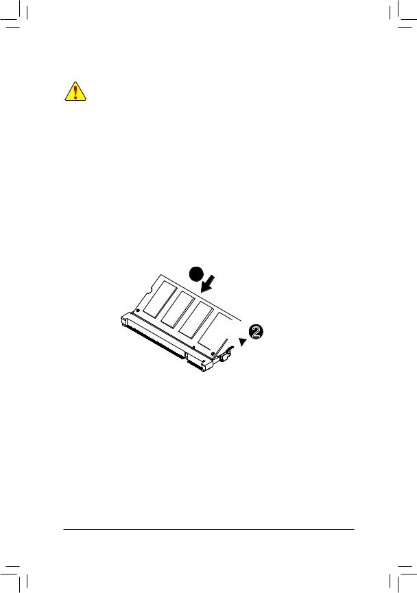
1-3-1 Installing a Memory
Installation Step:
Step 1. Align the memory with the SO-DIMM module and insert the SO-DIMM memory module into the SO-DIMM slot.
Please note that memory module has a foolproof insertion design. A memory module can be installed In only one direction.
Step 2. Push the memory and seat it firmly.
Step 3. Reverse the installation steps when you wish to remove the SO-DIMM module.
1

 2
2
Hardware Installation |
- 12 - |
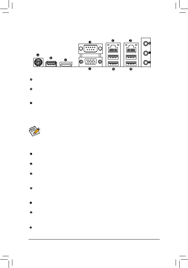
1-4 Back Panel Connectors
DC Power Jack
Connect the DC power to this port.
USB 3.0 Port
The USB port supports the USB 3.0 specification. Use this port for USB devices such as a USB keyboard/mouse, USB printer, USB flash drive and etc.
HDMI Port
The HDMI (High-Definition Multimedia Interface) provides an all-digital audio/video interface to transmit the uncompressed audio/video signals and is HDCP compliant. Connect the HDMI audio/video device to this port. The HDMI Technology can support a maximum resolution of 1920x1080p but the actual resolutions supported depend on the monitor being used.
• When After installing the HDMI device, make sure the default device for sound playback is the
HDMI device. (The item name may differ by operating system. Refer the figures below for details.), and enter BIOS Setup, then set Onboard VGA output connect to D-SUB/ HDMI under Advanced BIOS Features..
•Please note the HDMI audio output only supports AC3, DTS and 2-channel-LPCM formats. (AC3 and DTS require the use of an external decoder for decoding.)
Serial Port
Connects to serial-based mouse or data processing devices.
Video Port
The video in port allows connect to video in, which can also apply to video loop thru function.
RJ-45 LAN Port
The Gigabit Ethernet LAN port provides Internet connection at up to 1 Gbps data rate. The following describes the states of the LAN port LEDs.
USB 2.0 Port
The USB port supports the USB 2.0 specification. Use this port for USB devices such as a USB keyboard/mouse, USB printer, USB flash drive and etc.
Line In Jack (Blue)
The default line in jack. Use this audio jack for line in devices such as an optical drive, walkman, etc.
Line Out Jack (Green)
The default line out jack. Use this audio jack for a headphone or 2-channel speaker. This jack can be used to connect front speakers in a 4/5.1/7.1-channel audio configuration.
MIC In (Pink)
The default MIC In jack. Microphone cab be connected to MIC In jack.
- 13 - |
Hardware Installation |
Connection/ |
|
|
|
|
Activity LED |
|
|
|
|
|
|||||||||
Speed LED |
|
|
|
|
Connection/Speed LED: |
|
Activity LED: |
||||||||||||
|
|
|
|
|
|
|
|
|
|
|
|
|
|
|
|
||||
|
|
|
|
|
|
|
|
|
|
|
|
|
|
|
|
|
|
|
|
|
|
|
|
|
|
|
|
|
|
|
|
|
|
|
State |
Description |
|
State |
Description |
|
|
|
|
|
|
|
|
|
|
|
|
|
|
|
Orange |
1 Gbps data rate |
|
Blinking |
Data transmission or receiving is occurring |
|
|
|
|
|
|
|
|
|
|
|
|
|
|
|
Green |
100 Mbps data rate |
|
Off |
No data transmission or receiving is occurring |
|
|
|
|
|
|
|
|
|
|
|
|
|
|
|
|||||
|
|
|
|
LAN Port |
Off |
10 Mbps data rate |
|
|
|
||||||||||
•When removing the cable connected to a back panel connector, first remove the cable from your device and then remove it from the motherboard.
•When removing the cable, pull it straight out from the connector. Do not rock it side to side to prevent an electrical short inside the cable connector.
Hardware Installation |
- 14 - |

1-5 |
Internal Connectors |
|
|
|
|
|
|
|
|
|
|
|
3 |
|
2 |
|
25 |
|
12 |
9 |
8 |
7 |
1 |
|
26 |
|
10 |
6 |
|
||
|
|
|
11 13 5 |
|
|||
|
|
27 |
|
18 |
|||
|
|
|
|
||||
|
|
29 |
28 |
|
16 |
|
17 |
|
|
30 |
|
|
|
4 |
|
|
|
|
|
|
|
||
|
24 |
31 |
|
14 |
|
|
23 |
|
|
||
|
|
|
|
|
|
|
21 |
|
|
15 |
|
|
|
22 |
19 |
20 |
|
1) |
ATX_12V |
|
|
17) |
LVDS |
2) |
DC_IN |
|
|
18) |
JRS6 |
3) |
KB_MS |
|
|
19) |
SATA1 |
4) |
BKL_CN |
|
|
20) |
SATAPW_1 |
5) |
COM1 |
|
|
21) |
LPC |
6) |
JCOM1 |
|
|
22) |
F_PANEL |
7) |
JRS3 |
|
|
23) |
F_USB1 |
8) |
JRS2 |
|
|
24) |
GPIO_CNT |
9) |
JRS4 |
|
|
25) |
F_AUDIO |
10) |
JRS1 |
|
|
26) |
SPK_OUT |
11) |
COM3 |
|
|
27) |
CPU_FAN |
12) |
JCOM3 |
|
|
28) |
SYS_FAN |
13) |
COM4 |
|
|
29) |
BAT_CON |
14) |
COM5 |
|
|
30) |
CLR_CMOS |
15) |
COM6 |
|
|
31) |
AT_CN |
16)JP2
- 15 - |
Hardware Installation |
Read the following guidelines before connecting external devices:
•First make sure your devices are compliant with the connectors you wish to connect.
•Before installing the devices, be sure to turn off the devices and your computer. Unplug the power cord from the power outlet to prevent damage to the devices.
•After installing the device and before turning on the computer, make sure the device cable has been securely attached to the connector on the motherboard.
Hardware Installation |
- 16 - |
Loading...