


MP30-AR0
Motherboard for APM X-Gene X3-408 processor
User's Manual
Rev. 1101

Copyright
© 2015 GIGA-BYTE TECHNOLOGY CO., LTD. All rights reserved.
The trademarks mentioned in this manual are legally registered to their respective owners.
Disclaimer
Information in this manual is protected by copyright laws and is the property of GIGABYTE. Changes to the specifications and features in this manual may be made by GIGABYTE without prior notice. No part of this manual may be reproduced, copied, translated, transmitted, or published in any form or by any means without GIGABYTE's prior written permission.
Documentation Classifications
In order to assist in the use of this product, GIGABYTE provides the following types of documentations:
For detailed product information, carefully read the User's Manual.
For more information, visit our website at:
http://b2b.gigabyte.com
You are a professional?
Get an access to our complete source of sales, marketing & technical materials at:
http://reseller.b2b.gigabyte.com
https://www.facebook.com/gigabyteserver

Table of Contents
Box Contents.................................................................................................................... |
|
4 |
MP30-AR0 Motherboard Layout...................................................................................... |
5 |
|
Block Diagram.................................................................................................................. |
7 |
|
Chapter 1 Hardware Installation...................................................................................... |
8 |
|
1-1 |
Installation Precautions..................................................................................... |
8 |
1-2 |
Product Specifications...................................................................................... |
9 |
1-3 |
Installing the Memory...................................................................................... |
10 |
|
1-3-1 Four Channel Memory Configuration...................................................................... |
10 |
|
1-3-2 Installing a Memory ................................................................................................ |
11 |
1-4 |
Back Panel Connectors.................................................................................. |
12 |
1-5 |
Internal Connectors........................................................................................ |
14 |
Chapter 2 UBOOT Configuration................................................................................... |
22 |
|
- 3 -

Box Contents
Motherboard
Four SATA 6Gb/s cables
User's Manual
I/O Shield
•The box contents above are for reference only and the actual items shall depend on the product package you obtain. The box contents are subject to change without notice.
•The motherboard image is for reference only.
- 4 -

MP30-AR0 Motherboard Layout
1 |
2 |
3 |
4 |
5 |
6 |
7 |
8
27 |
|
|
|
|
28 |
29 |
30 |
|
|
|
|
|
|
|
|
|
32 |
|
9 |
26 |
|
33 |
|
10 |
|
|
|
|
|
|
|
34 |
|
11 |
257 |
|
35 |
13 |
12 |
|
|
24 |
312 |
|
23 |
||
|
||
22 |
|
|
21 |
|
14
20 |
19 |
18 |
17 |
16 |
15 |
- 5 -

Item |
Code |
Description |
|
1 |
LED_STA |
System status LED |
|
2 |
USB2_MLAN |
BMC Management LAN port (top)/USB 2.0 ports |
|
(bottom) |
|||
|
|
||
3 |
VGA1_COM1 |
Serial port (top)/VGA port (bottom) |
|
4 |
SFP+_1_2 |
10G Fiber LAN ports |
|
5 |
LAN1_2 |
LAN ports |
|
6 |
SW_PWR |
Power button/LED |
|
7 |
SW_ID |
ID switch button/LED |
|
8 |
CPU_FAN |
CPU fan connector |
|
9 |
DIMM_P0_A0 |
Channel 1 slot 0 |
|
10 |
DIMM_P0_A1 |
Channel 1 slot 1 |
|
11 |
DIMM_P0_B0 |
Channel 2 slot 0 |
|
12 |
DIMM_P0_B1 |
Channel 2 slot 1 |
|
13 |
CPU0 |
ARM CPU |
|
14 |
P12V_AUX1 |
4 pin power connector |
|
15 |
ATX1 |
24 pin main power connector |
|
16 |
SYS_FAN1 |
System fan connector#1 |
|
17 |
FP_1 |
Front panel header (for Server system) |
|
18 |
SYS_FAN2 |
System fan connector#2 |
|
19 |
PMBUS |
PMBus header |
|
20 |
CLR_CMOS |
Clear CMOS jumper |
|
21 |
SYS_FAN3 |
System fan connector#3 |
|
22 |
BP_1 |
HDD back plane board header |
|
23 |
CASE_OPEN |
Case open intrusion alert header |
|
24 |
IPMB |
IPMB connector |
|
25 |
SYS_FAN4 |
System fan connector#4 |
|
26 |
SATA_DOM0 |
SATA port 3 DOM support jumper |
|
27 |
SATA0/1/2/3 |
SATA3 6Gb/s connectors |
|
28 |
PCIE_2 |
PCI Express x16 slot |
|
29 |
BAT |
Battery socket |
|
30 |
PCIE_1 |
PCI Express x16 slot |
|
31 |
LED_BMC |
BMC firmware readiness LED |
|
32 |
DIMM_P0_C0 |
Channel 3 slot 0 |
|
33 |
DIMM_P0_C1 |
Channel 3 slot 1 |
|
34 |
DIMM_P0_D0 |
Channel 4 slot 0 |
|
35 |
DIMM_P0_D1 |
Channel 4 slot 1 |
CAUTION! If a SATA type hard drive is connected to the motherboard, please ensure the jumper is closed and set to 2-3 pins (Default setting), in order to reduce any risk of hard disk damage. Please refer to Page 22 for SATA_DOM0 jumper setting instruction.
- 6 -
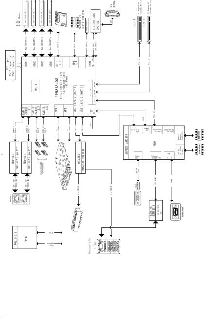
Block Diagram
- 7 -
 Loading...