

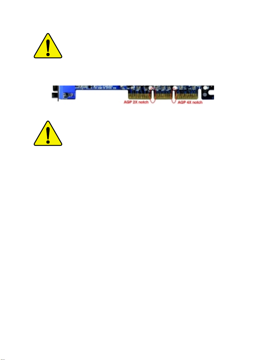
When you installing AGP card, please make sure the
following notice is fully understood and practiced. If your
AGP card has "AGP 4X notch"(show below), please make
sure your AGP card is AGP 4X (1.5V).
Do not use AGP 2X card (3.3V) in this motherboard. It will
burn and damage the motherboard due to Intel
®
850 chipset
can't support AGP 2X(3.3V).
Example 1: Diamond Vipper V770 golden finger is compatible
with 2X/4X mode AGP slot. It can be switched between AGP 2X
(3.3V) or 4X(1.5V) mode by adjusting the jumper. The factory
default for this card is 2X(3.3V). If you install this card in
GA-8ITX3 (or any AGP 4X only) motherboards without switching
the jumper to 4X mode (1.5V), it will burn the motherboard.
Example 2: ATi Rage 128 Pro (Power Color) & SiS 305 golden
finger is compatible with 2X/4X mode AGP slot, but it supports
2X(3.3V) only. If you install this card in GA-8ITX3 (or any AGP
4X only) motherboards, it will burn the motherboard.
The author assumes no responsibility for any errors
or omissions that may appear in this document nor
does the author make a commitment to up
date the information contained herein.
Third-party brands and names are the property of
their respective owners.
Please do not remove any labels on motherboard, this
may void the warranty of this motherboard.
Due to rapid change in technology, some of the
specifications might be out of date before pwblicution
of this booklet.

DECLARATION OF CONFORMITY
Per FCC Part 2 Section 2.1077(a)
Responsible Party Name:
Address:
Phone/Fax No:
hereby declares that the product
Product Name:
Model Number:
Conforms to the following specifications:
FCC Part 15, Subpart B, Section 15.107(a) and Section 15.109(a),
Class B Digital Device
Supplementary Information:
This device complies with part 15 of the FCC Rules. Operation is
subject to the following two conditions: (1) This device may not
cause harmful and (2) this device must accept any inference received,
including that may cause undesired operation.
Representative Person’s Name:
Signature:
G.B.T. INC.
18305 Valley Blvd., Suite#A LA
Puent, CA 91744
(818) 854-9338/ (818) 854-9339
Motherboard
GA-8ITX3
ERIC LU
Eric Lu
Date:
Oct. 19,2001

Ausschlager Weg 41, 1F, 20537 Hamburg, Germany
( description of the apparatus, system, installation to which it refers)
(reference to the specification under which conformity is declared)
in accordance with 89/336 EEC-EMC Directive
EN 55011 Limits and methods of measurement
EN 55013
EN 55014 Limits and methods of measurement
EN 55015 Limits and methods of measurement
EN 55020
EN 55022 Limits and methods of measurement
DIN VDE 0855
part 10
part 12
of radio disturbance characteristics of
industrial,scientific and medical (ISM
high frequency equipment
Limits and methods of measurement
of radio disturbance characteristics of
broadcast receivers and associated
equipment
of radio disturbance characteristics of
household electrical appliances,
portable tools and similar electrical
apparatus
of radio disturbance characteristics of
fluorescent lamps and luminaries
Immunity from radio interference of
broadcast receivers and associated
equipment
of radio disturbance characteristics of
information technology equipment
Cabled distribution systems; Equipment
for receiving and/or distribution from
sound and television signals
Declaration of Conformity
We, Manufacturer/Importer
(full address)
G.B.T. Technology Träding GMbH
declare that the product
Mother Board
GA-8ITX3
is in conformity with
EN 61000-3-2*
EN 60555-2
EN 61000-3-3* Disturbances in supply systems cause
EN 60555-3
EN 50081-1
EN 50082-1
EN 55081-2
EN 55082-2
ENV 55104
EN50091-2
Disturbances in supply systems cause
by household appliances and similar
electrical equipment “Harmonics”
by household appliances and similar
electrical equipment “Voltage fluctuations”
Generic emission standard Part 1:
Residual commercial and light industry
Generic immunity standard Part 1:
Residual commercial and light industry
Generic emission standard Part 2:
Industrial environment
Generic emission standard Part 2:
Industrial environment
lmmunity requirements for household
appliances tools and similar apparatus
EMC requirements for uninterruptible
power systems (UPS)
CE marking
EN 60065
EN 60335
The manufacturer also declares the conformity of above mentioned product
with the actual required safety standards in accordance with LVD 73/23 EEC
Safety requirements for mains operated
electronic and related apparatus for
household and similar general use
Safety of household and similar
electrical appliances
(Stamp)
EN 60950
EN 50091-1
Manufacturer/Importer
Date : Oct. 19, 2001
(EC conformity marking)
Signature:
Name:
Rex Lin
Rex Lin

GA-8ITX3
Pentium®4 Processor Motherboard
USER’S MANUAL
Pentium®4 Processor Motherboard
Rev. 1.0 First Edition
12ME-8ITX3-1001

GA-8ITX3 Motherboard
Table of Contect
Revision History.....................................................................................4
Item Checklist .........................................................................................4
WARNING!...............................................................................................5
Chapter 1 Introduction.............................................................................6
Summary of Features .................................................................................. 6
GA-8ITX3 Motherboard Layout................................................................... 8
Chapter 2 Hardware Installation Process................................................9
Step 1: Install the Central Processing Unit (CPU).....................................10
Step1-1:CPU Installation....................................................................................11
Step 1-2: CPU Heat Sink Installation ................................................................. 12
Step 2: Install memory modules................................................................ 1 3
Step 2-1:Introduce RIMM (Rambus In-line Memory Module) ............................ 14
Step 3: Install expansion cards .................................................................15
Step 4: Connect ribbon cables, cabinet wires, and power supply ...........16
Step 4-1: I/O shield Introduction........................................................................ 16
Step 4-2:Connectors Introduction...................................................................... 18
Step 4-3: ATX 12V Power Supply Introduction.................................................. 25
Step 4-4: 6 Pin Aux. Power Connector............................................................. 25
2

Table of Content
Chapter 3 BIOS Setup ..........................................................................26
The Main Menu (For example: BIOS Ver. :F1)......................................... 28
Standard CMOS Features ......................................................................... 30
BIOS Features Setup.................................................................................33
Chipset Features Setup............................................................................. 35
Power Management Setup .......................................................................37
PNP/PCI Configuration..............................................................................41
Load Fail-Safe Defaults............................................................................. 43
Load Optimized Defaults...........................................................................44
Integrated Peripherals ............................................................................... 45
Hardware Monitor & MISC Setup..............................................................51
Set Supervisor / User Password ................................................................ 5 3
IDE HDD Auto Detection............................................................................54
Save & Exit Setup.......................................................................................55
Exit Without Saving .................................................................................... 56
Chapter 4 Technical Reference ............................................................57
Performance List ....................................................................................... 57
Block Diagram........................................................................................... 58
Q-Flash Utility Introduction........................................................................59
@ BIOS Introduction.................................................................................. 61
TM
Easy TuneIII
Introduction .......................................................................62
Chapter 5 Appendix..............................................................................63
3

GA-8ITX3 Motherboard
Revision History
Revision Revision Note Date
1.0 Initial release of the GA-8ITX3 motherboard user's manual. Oct.2001
Item Checklist
The GA-8ITX3 motherboard
IDE cable x 1 / Floppy cable x 1
USB cable x 1
CD for motherboard driver & utility (IUCD)
GA-8ITX3 user’s manual
I/O Shield
Processor heat sink attach clips x2
Screw x 4
Quick PC Installation Guide
CRIMM x 2
4

WARNING!
WARNING!
Computer motherboards and expansion cards contain very delicate Integrated Circuit (IC) chips. To
protect them against damage from static electricity, you should follow some precautions whenever you
work on your computer.
1. Unplug your computer when working on the inside.
2. Use a grounded wrist strap before handling computer components. If you do not have
one, touch both of your hands to a safely grounded object or to a metal object, such as
the power supply case.
3. Hold components by the edges and try not touch the IC chips, leads or connectors, or
other components.
4. Place components on a grounded antistatic pad or on the bag that came with the
components whenever the components are separated from the system.
5. Ensure that the A TX power supply is switched off before you plug in or remove the A TX
power connector on the motherboard.
Installing the motherboard to the chassis…
If the motherboard has mounting holes, but they don’t line up with the holes on the base and there are
no slots to attach the spacers, do not become alarmed you can still attach the spacers to the mounting
holes. Just cut the bottom portion of the spacers (the spacer may be a little hard to cut off, so be careful
of your hands). In this way you can still attach the motherboard to the base without worrying about short
circuits. Sometimes you may need to use the plastic springs to isolate the screw from the motherboard
PCB surface, because the circuit wire may be near by the hole. Be careful, don’t let the screw contact
any printed circuit write or parts on the PCB that are near the fixing hole, otherwise it may damage the
board or cause board malfunctioning.
5

GA-8ITX3 Motherboard
Chapter 1 Introduction
Summary of Features
Form Factor 30.5cm x 24.5cm ATX size form factor, 4 layers PCB.
CPU Socket 423 processor
Intel Pentium®4 400MHz FSB
2nd Level cache depend on CPU
Chipset Chipset 82850 HOST/AGP/Controller
82801BA(ICH2) I/O Controller Hub
Memory 4 184-pin RIMM Sockets
Dual direct RDRAM channel
Supports up to 2GB (Max)
I/O Control Winbond W83627HF
Slots 1 CNR(Communication and Networking Riser) Slot
1 AGP support 4X(1.5V) device
5 PCI slot supports 33MHz & PCI 2.2 compliant
On-Board IDE An IDE controller on the Intel 82801BA PCI chipset
provides IDE HDD/CD-ROM with PIO, Bus Master (Ultra
DMA33/AT A66/A T A100) operation modes.
Can connect up to four IDE devices
On-Board Peripherals 1 Floppy port supports 2 FDD with 360K, 720K,1.2M, 1.44M
and 2.88M bytes.
1 Parallel port supports Normal/EPP/ECP mode
2 Serial ports (COMA&COMB)
4 USB ports (Rear USB x 2, Front USB x 2)
1 IrDA connector for IR/CIR
Hardware Monitor CPU/Power/System Fan Revolution detect
CPU Overheat Warning
System Voltage Detect
to be continued......
6

On-Board Sound AC97 CODEC
Line In/Line Out/Mic In/CD In/Game Port
PS/2 Connector PS/2 Keyboard interface and PS/2 Mouse interface
BIOS Licensed AMI BIOS, 2M bit FWH
Supports Dual BIOS
Additional Features PS/2 Keyboard power on by password
PS/2 Mouse power on
External Modem wake up
STR(Suspend-T o-RAM)
Wake on LAN
AC Recovery
USB KB/Mouse wake up from S3
Supports @BIOS
Supports EasyTuneIII
Introduction
Please set the CPU host frequency in accordance with your processor’s specifications.
We don’t recommend you to set the system bus frequency over the CPU’s specification
because these specific bus frequencies are not the standard specifications for CPU,
chipset and most of the peripherals. Whether your system can run under these specific
bus frequencies properly will depend on your hardware configurations, including CPU,
Chipsets,SDRAM,Cards….etc.
7
GA-8ITX3 Motherboard
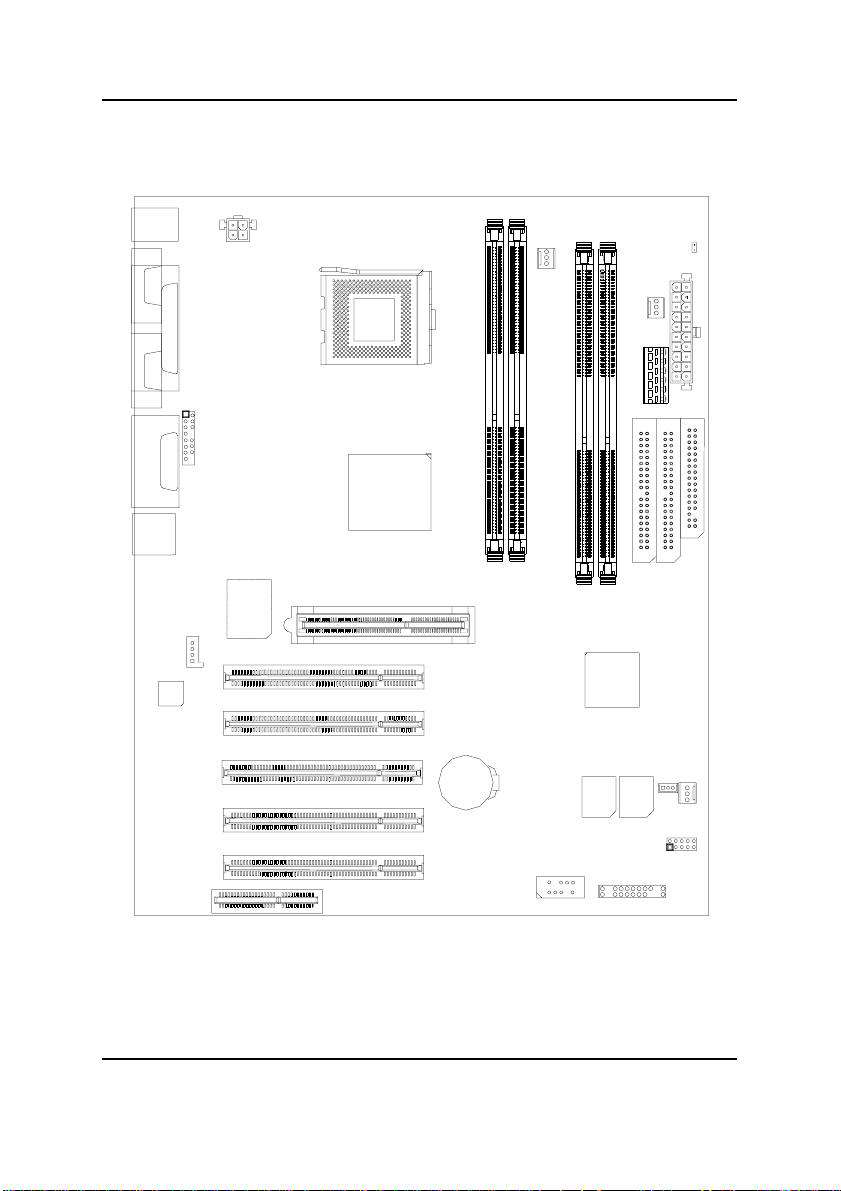
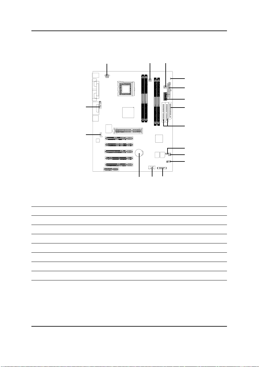
GA-8ITX3 Motherboard Layout
KB/MOUSE
COMA
LPT
COMB
LINE_OUT
GAME
LINE_IN
MIC_IN
USB
J2
CODEC
J16
FRONT AUDIO
W83627
SOCKET423
TEHAMA
PCI3
PCI1
PCI2
PCI4
AGP1
BAT1
GA-8ITX3
RIMM2
RIMM1
CPU_FAN
RIMM3
ICH2
BACKUP
J18
RIMM4
BIOS
PWR_FAN
IDE2
MAIN
BIOS
J17
LED2
IDE1
JP15
J15
FLOPPY
SYS_FAN
CNR
PCI5
CN10
J7
8
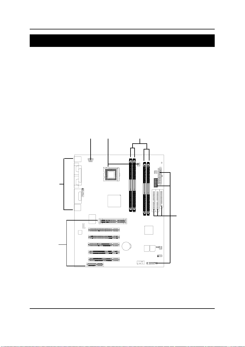
Hardware Installation Process
Chapter 2 Hardware Installation Process
T o set up your computer , you must complete the following setups:
Step 1- Install the Central Processing Unit (CPU)
Step 2- Install memory modules
Step 3- Install expansion cards
Step 4- Connect ribbon cables, cabinet wires, and power supply
Step 5- Setup BIOS software
Step 6- Install supporting software tools
Step 4
Step 3
Step 4
Step 1
Step 2
Step 4
9

GA-8ITX3 Motherboard
Step 1: Install the Central Processing Unit (CPU)
Befor You will know.....
Y ou may use the 4 screws which come with the mainboard to reinforce the support between P4
CPU heat-sink on the mainboard and chassis.
In order to follow the installation steps below; your chassis must be WILLMETTE/850 board design
compatible.
Step1: The 4 new mounting holes on the chassis
are for additional support for P4 CPU heatsink on the mainboard.
Step2: Please remove 4 sets of plastic Push-pins
as indicated on Figure2. Remove the white
pins first, then black pins as indicated on
Figure3.
Step3:
Figure1 Figure2
Step4:Fit the 4 screws with 2 CPU retention
modules on the chassis.
Figure3
10
Figure4
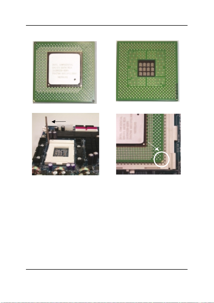
Step1-1:CPU Installation
Hardware Installation Process
CPU Top View
CPU Bottom View
Socket Actuation Lever
Pin1 indicator
1. Pull up the CPU socket level
and up to 90-degree angle.
3. Press down the CPU socket
lever and finish CPU installation.
Please make sure the CPU type is supported by the motherboard.
2. Locate Pin 1 in the socket and look
for a (golden) cut edge on the CPU
upper corner. Then insert the CPU
into the socket.
11
GA-8ITX3 Motherboard
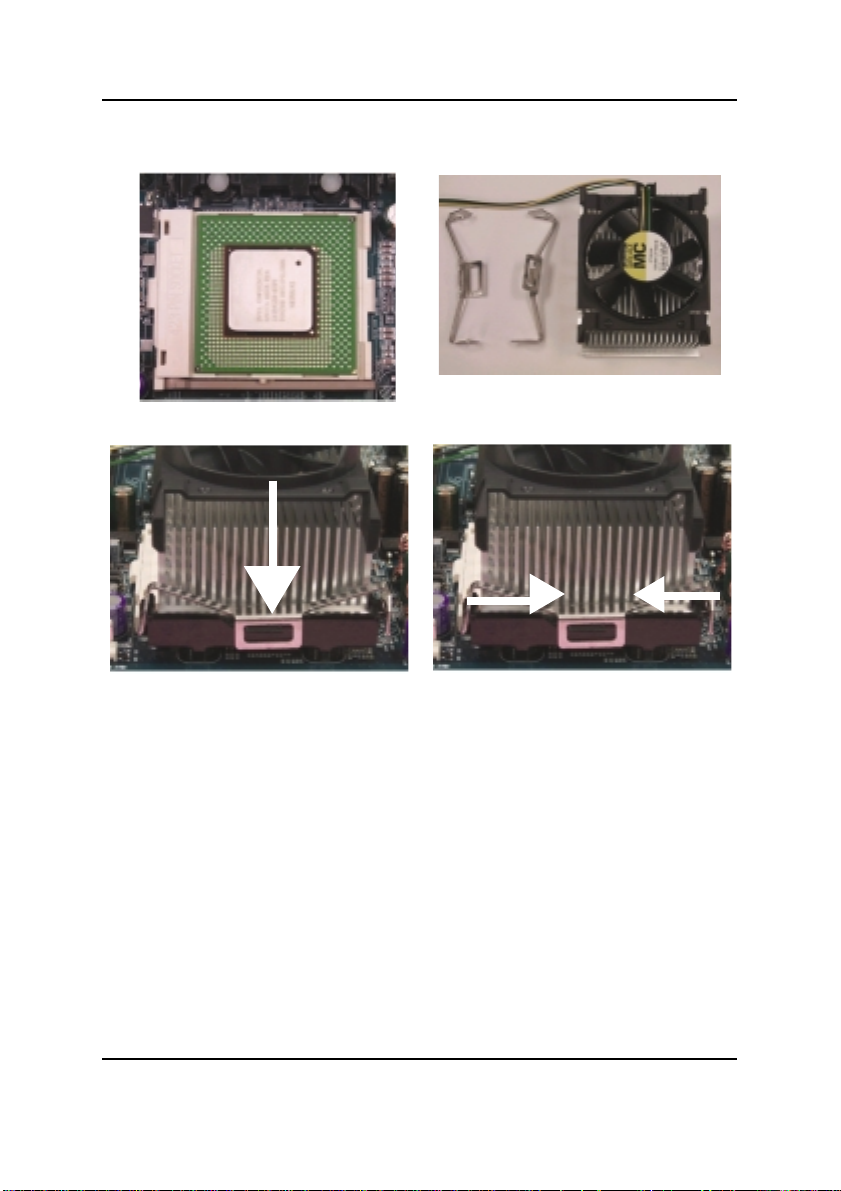
Step 1-2: CPU Heat Sink Installation
1.Align CPU and insert it
3.Slip the bracket on to the CPU retention and press both end to clip it on the retention.
2.Use qualified fan approved by Intel.
Please use Intel approved cooling fan.
We recommend you to apply the thermal paste to provide better heat
conduction between your CPU and heatsink.
Make sure the CPU fan power cable is plugged in to the CPU fan connector,
this completes the installation.
Please refer to CPU heat sink user’s manual for more detail installation
procedure.
12
Hardware Installation Process
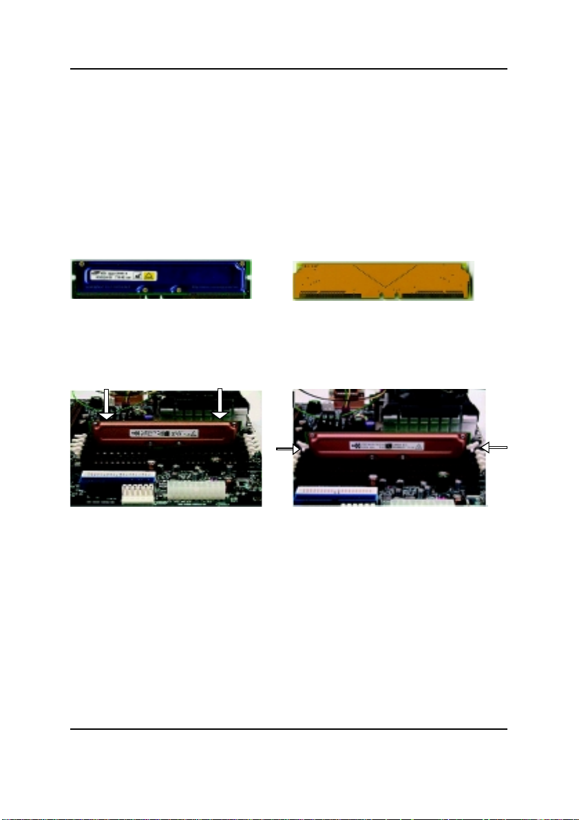
Step 2: Install memory modules
The motherboard has 4 Rambus In-line Memory Module (RIMM) sockets. The BIOS will automatically detect memory type and size. To install the memory module, just push it vertically into the
RIMM Slot .The RIMM module can only fit in one direction due to the two notches. Please note; Both
RIMM modules inserted on RIMM1 and RIMM3 slots are recommended to have the same size,
frequency. If not, the larger sized module will l be automatically re-sized by BIOS to match the
smaller sized module. The same rule applies to both RIMM2 and RIMM4 slots.
You can insert two RIMMs or four RIMMs into RIMM slots, but C-RIMM (Continuity RIMM)
modules must be inserted into the empty slots.
RIMM
Check RIMM module if it is supported by the
M/B.
Insert the RIMM module into the slot.
Push the ejector tab towards the RIMM.
CRIMM
When STR/RIMM LED is ON, you do not install / remove RDRAM from socket.
Please note that the DIMM module can only fit in one direction due to the two
notches. Wrong orientation will cause improper installation. Please change
the insert orientation.
13
GA-8ITX3 Motherboard
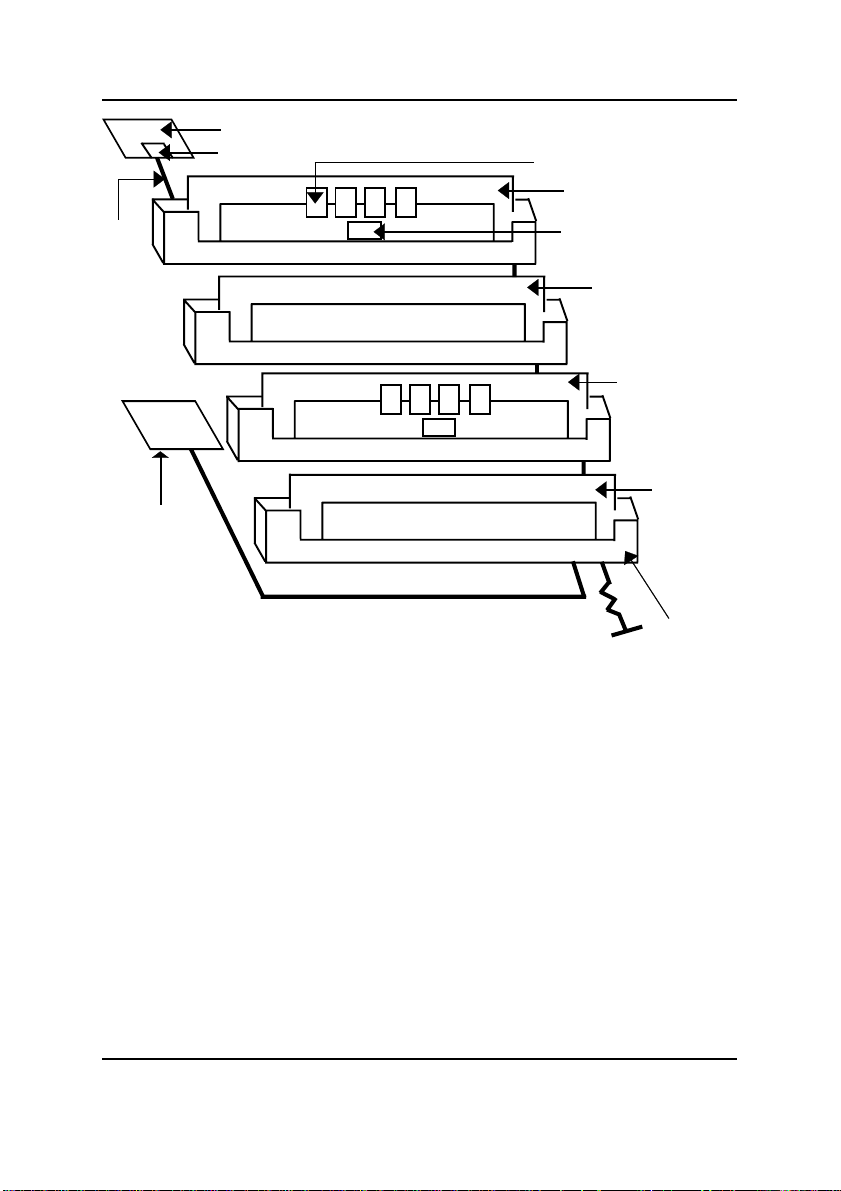
Master Device
Direct Rambus ASIC Cell(RAC)
Rambus Channel
Direct Rambus
Clock Generator
(DRCG)
Step 2-1:Introduce RIMM (Rambus In-line Memory Module)
Direct Rambus Memory Controller
Directly support a Dual Direct Rambus * Channel
Supports 300&400 MHz Direct Rambus * Channel @ 100MHz host bus frequency.
Maximum memory array size up to 256MB using 64Mb/72Mb, 512MB using 128Mb/144Mb,
1GB using 256Mb/288Mb DRAM technology
Supports up to 32 Direct Rambus devices per channel
Supports a maximum DRAM address decode space of 4GB
Configurable optional ECC operation
ECC with single bit Error Correction and multiple bit Error Detection
Single bit errors corrected and written back to memory (auto-scrubbing)
Parity mode not supported
APIC memory space in hardware. It is the BIOS or system designer's responsibility to limit DRAM
population so that adequate PCI, AGP, High BIOS, and APIC memory space can be allocated.
Direct RDROM
RIMM Module
SPD ROM
RIMM Continuity
Module
RIMM Module
RIMM
Continuity
Module
RIMM
Connector
14
Hardware Installation Process
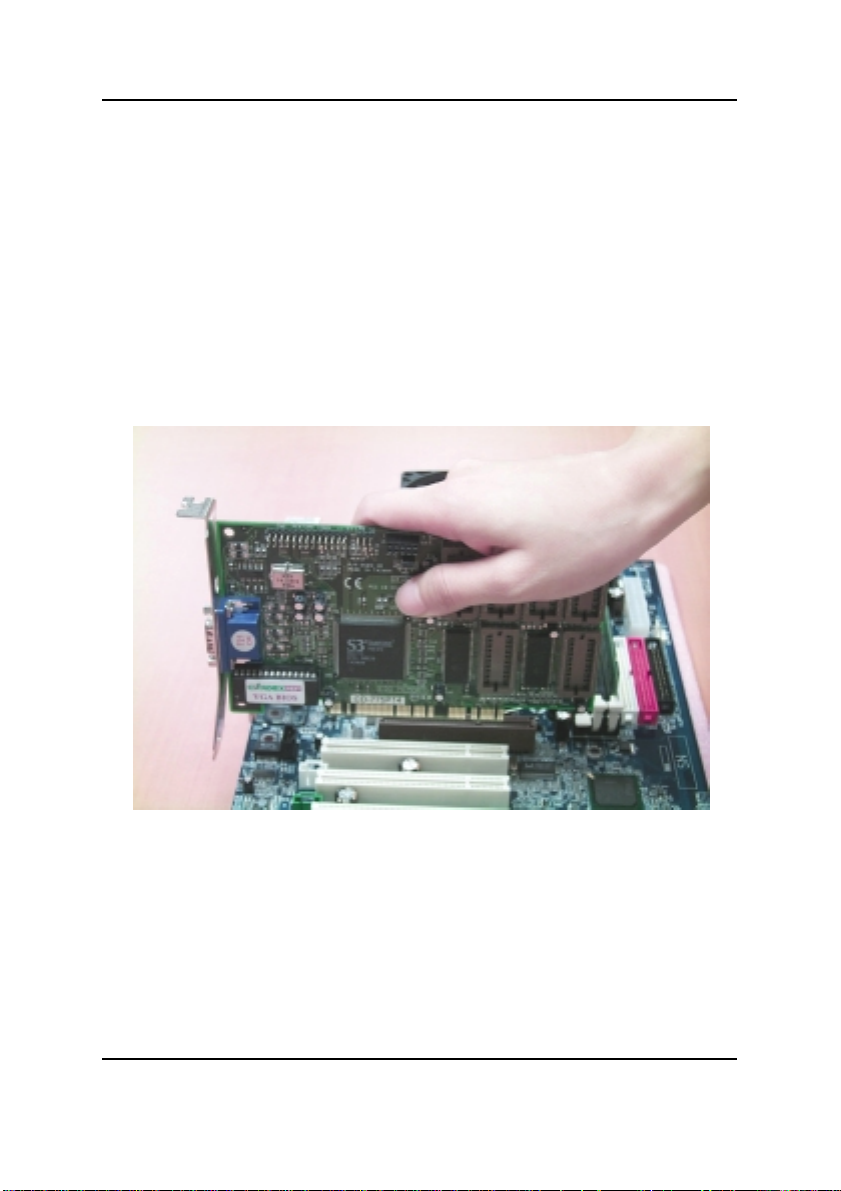
Step 3: Install expansion cards
1. Read the related expansion card’s instruction document before install the expansion card into
the computer.
2. Remove your computer’s chassis cover, necessary screws and slot bracket from the computer.
3. Press the expansion card firmly into expansion slot in motherboard.
4. Be sure the metal contacts on the card are indeed seated in the slot.
5. Replace the screw to secure the slot bracket of the expansion card.
6. Replace your computer’s chassis cover.
7. Power on the computer, if necessary, setup BIOS utility of expansion card from BIOS.
8. Install related driver from the operating system.
15
GA-8ITX3 Motherboard
Step 4: Connect ribbon cables, cabinet wires, and power
supply
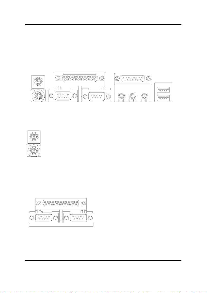
Step 4-1: I/O shield Introduction
PS/2 Keyboard and PS/2 Mouse Connector
PS/2 Mouse Connector
(6 pin Female)
PS/2 Keyboard Connector
(6 pin Female)
This connector supports standard PS/2
keyboard and PS/2 mouse.
Parallel Port and Serial Ports (COMA/COMB)
Parallel Port
(25 pin Female)
This connector supports 2 standard COM ports
and 1 Parallel port. Device like printer can be
connected to Parallel port ; mouse and modem
etc can be connected to Serial ports.
COMA COMB
Serial Ports (9 pin Male)
16
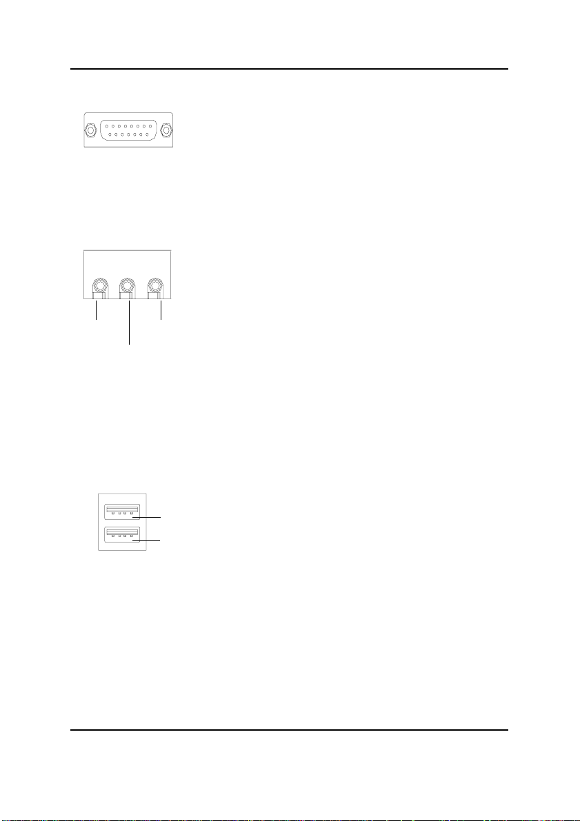
Game /MIDI Ports
Joystick/ MIDI (15 pin Female)
Audio Connectors
Hardware Installation Process
This connector supports joystick, MIDI keyboard and other
relate audio devices.
After install onboard audio driver, you may connect
speaker to Line Out jack, micro phone to MIC In jack.
Device like CD-ROM , walkman etc can be connected
to Line-In jack.
Line Out
MIC In
Line In
USB Connector
USB 0
USB 1
Before you connect your device(s) into USB connector(s),
please make sure your device(s) such as USB keyboard,
mouse, scanner, zip,speaker..etc. Have a standard USB
interface. Also make sure your OS (Win 95 with USB
supplement, Win98, Windows 2000, Windows ME, Win
NT with SP 6) supports USB controller. If your OS does not
support USB controller, please contact OS vendor for possible patch or driver upgrade. For more information please
contact your OS or device(s) vendors.
17
GA-8ITX3 Motherboard
Step 4-2:Connectors Introduction
A
P
O
B
C
D
E
F
G
H
I
J
K
L
M
N
A) J16 I) J17
B) CPU_FAN J) SYS_FAN
C) PWR_FAN K) JP15
D) LED2 L) J7
E) J15 M) CN10
F) J18 N) BAT1
G) FLOPPY O) J2
H) IDE1/IDE2 P) FRONT AUDIO
18
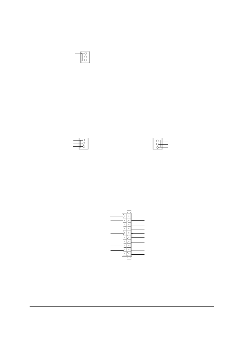
B) CPU_FAN (CPU FAN Connector)
Hardware Installation Process
GND
+12V/Control
Sense
1
C) PWR_FAN (Power FAN Connector)
GND
+12V/Control
Sense
1
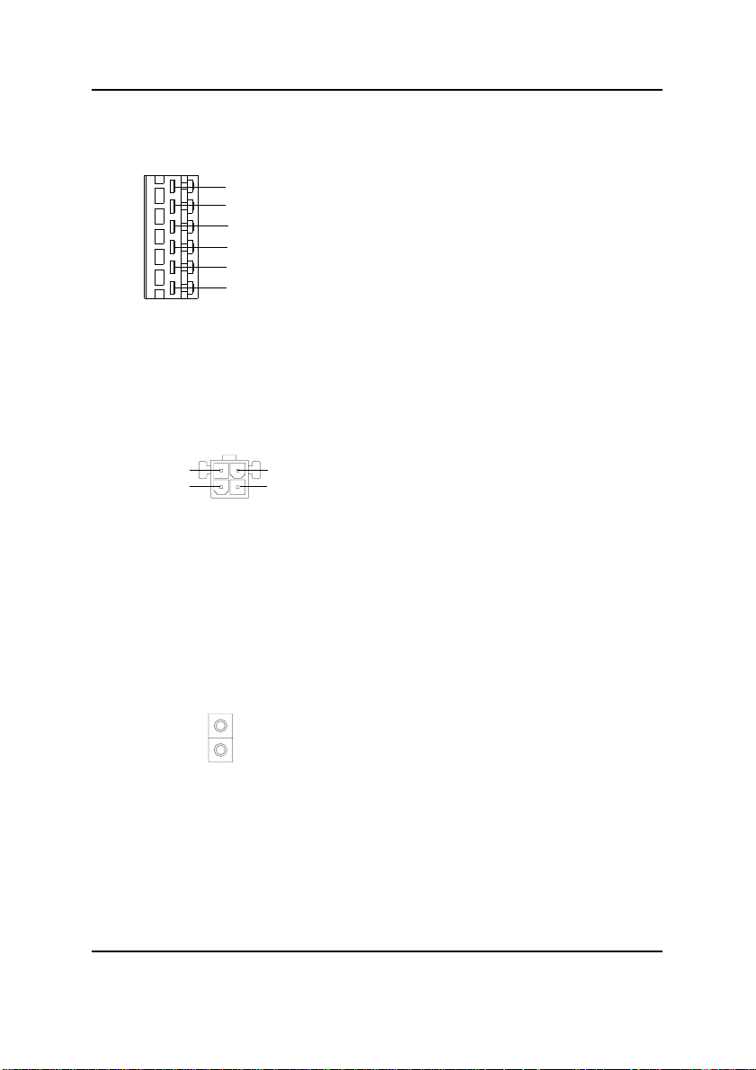
E) J15 (ATX Power)
5V SB (Stand by +5V)
+12V
Power Good
GND
VCC
GND
VCC
GND
3.3V
3.3V
Please note, a proper installation of the CPU
cooler is essential to prevent the CPU from
running under abnormal condition or damaged
by overheating.The CPU fan connector
supports Max. current up to 600mA .
J) SYS_FAN (System FAN Connector)
Sense
1
20
VCC
VCC
-5V
GND
GND
GND
PS-ON(Soft On/Off)
GND
-12V
1
3.3V
+12V/Control
GND
AC power cord should only be connected to your power supply unit after A TX power cable and other
related devices are firmly connected to the mainboard.
19
GA-8ITX3 Motherboard
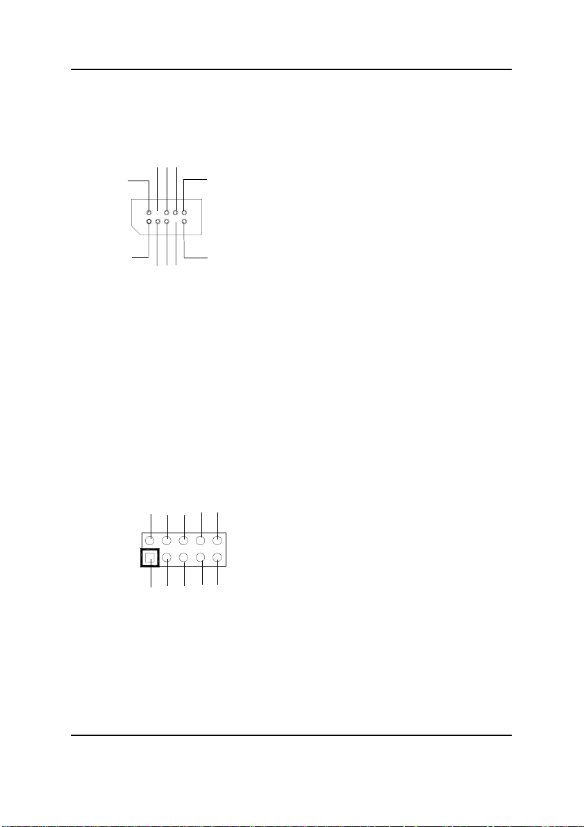
F) J18 (AUX Power)
6
+5VDC
+3.3VDC
+3.3VDC
GND
GND
GND
1
A) J16 (AUX +12V Power Connector)
3
+12V
GND
4
+12V
GND
1
2
D) LED2 (RIMM LED)
The 6-pin Aux. Power connector provides
additional current to meet the board's
+3.3VDC and +5VDC requirments.
Please refer to the detail on P.24
This connector (A TX +12V) is used only
for CPU Core Voltage.
Do not remove memory modules while
RIMM LED is on. It might cause short or
other unexpected damages due to the
2.5V stand by voltage. Remove memory
modules only when STR function is
disabled by jumper and AC Power cord is
disconnected.
20
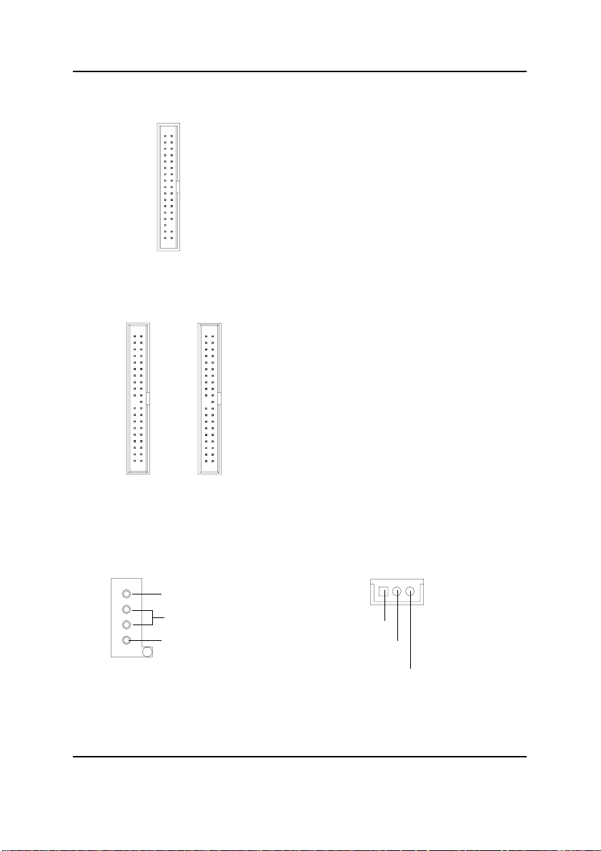
G) FLOPPY (Floppy Connector)
1
H) IDE1/IDE2 [IDE1 / IDE2 Connector(Primary/Secondary]
Important Notice:
Please connect first harddisk to IDE1
and connect CDROM to IDE2.
Hardware Installation Process
1
IDE2
O) J2 (CD Audio Line In)
CD-R
GND
1
CD-L
1
IDE1
I) J17 (Wake On Lan)
1
+5V SB
GND
Signal
21
GA-8ITX3 Motherboard
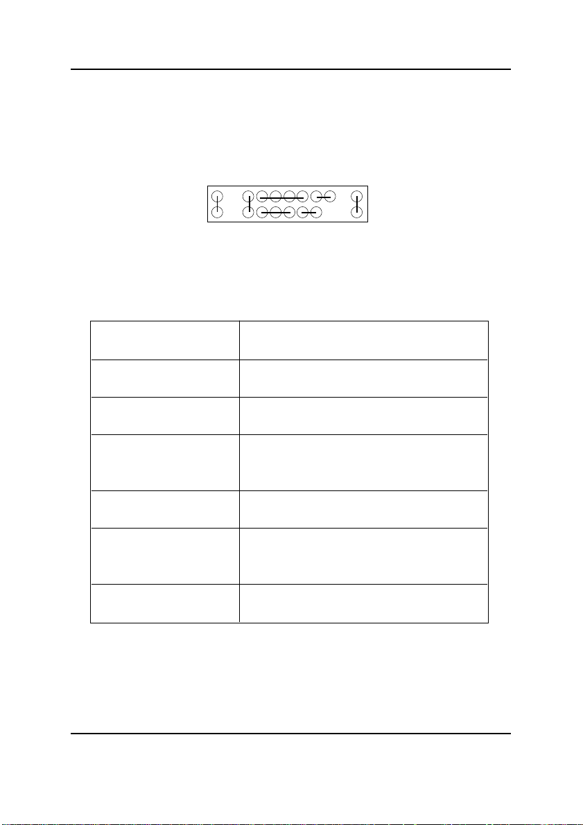
L) J7 (2x11 pins jumper)
RE
1
1
1
GN
HD
SPK
1
P-P-P+ PW GD
GN (Green Switch) Open: Normal Operation
Close: Entering Green Mode
GD (Green LED) Pin 1: LED anode(+)
Pin 2: LED cathode(-)
HD (IDE Hard Disk Active LED) Pin 1: LED anode(+)
Pin 2: LED cathode(-)
SPK (Speaker Connector) Pin 1: VCC(+)
Pin 2- Pin 3: NC
Pin 4: Data(-)
RE (Reset Switch) Open: Normal Operation
Close: Reset Hardware System
P-P-P+(Power LED) Pin 1: LED anode(+)
Pin 2: LED cathode(-)
Pin 3: LED cathode(-)
PW (Soft Power Connector) Open: Normal Operation
Close: Power On/Off
1
Please connect the power LED, PC speaker, reset switch and power switch etc of your chassis front
panel to the front panel jumper according to the pin assignment above.
22
M) CN10 (Front USB Connector)
USB D3+
NC
USB D3-
GND
Power
1
Power
USB D2-
GND
NC
USB D2+
K) JP15 (IR/CIR)
GND
NC
VCC
NC
CIRRX
1
VCC
NC
IRRX
GND
IRTX
Hardware Installation Process
Be careful with the polarity of the front
panel USB connector. Check the pin
assignment while you connect the front
panel USB cable. Please contact your
nearest dealer for optional front panel
USB cable.
Make sure the pin 1 on the IR device is
aling with pin one the connector. To
enable the IR/CIR function on the board,
you are required to purchase an option IR/
CIR module. For detail information please
contact your autherized Giga-Byte
distributor.
T o use IR function only , please connect IR
module to Pin1 to Pin5.
23
 Loading...