

Page 1

GA-8IRX
P4 Titan DDR Motherboard
USER’S MANUAL
Pentium®4 Processor Motherboard
Rev. 2.0 Third Edition
12M D-8IRX-2003
Page 2
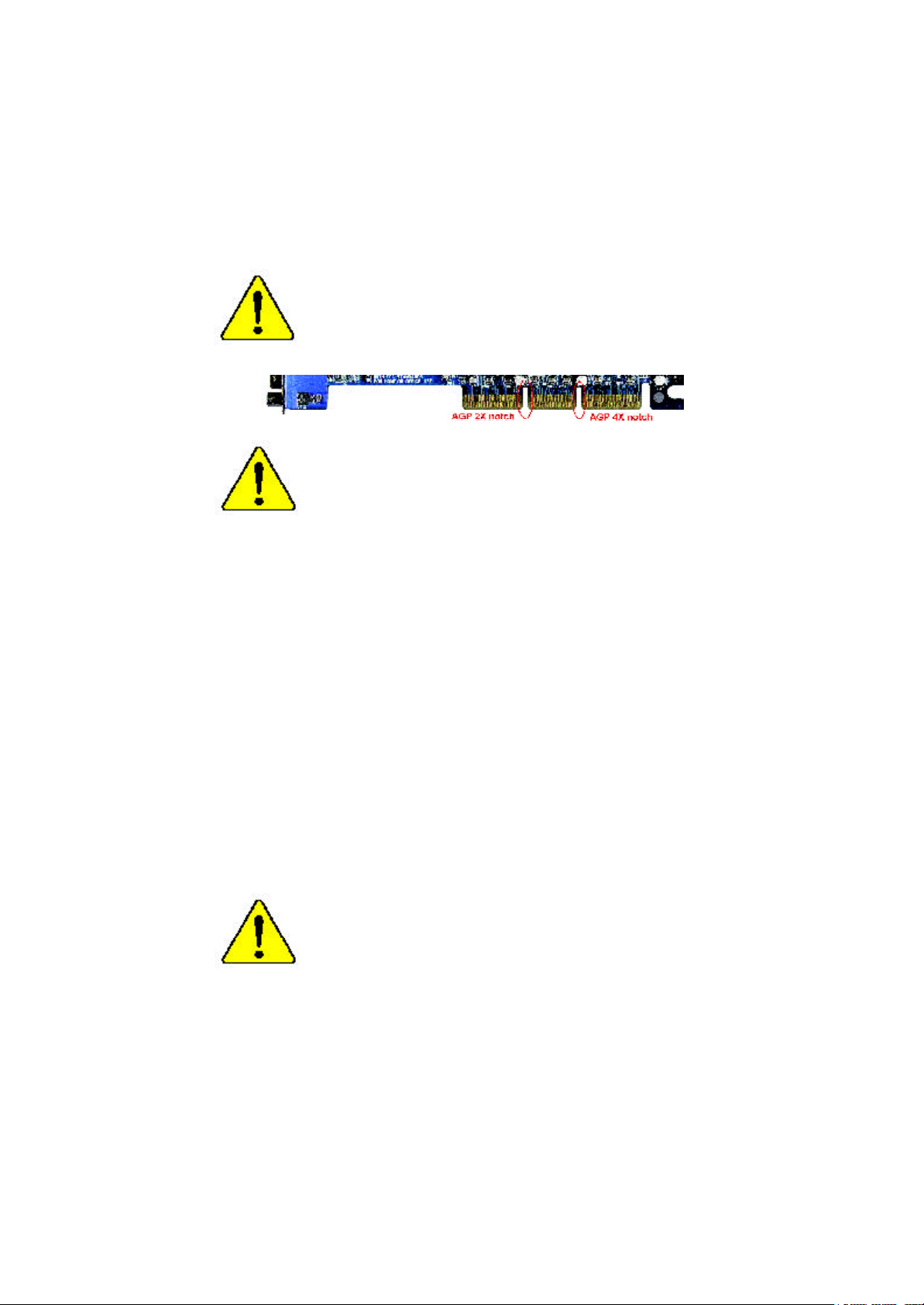
When you installing AGP card, please make sure the follow
ing notice is fully understood and practiced. If your AGP
card has "AGP 4X notch"(show below), please make sure
your AGP card is AGP 4X (1.5V).
Do not use AGP 2X card (3.3V) in this motherboard. It will
burn and damage the motherboard due to Intel® 845 chipset
can't support AGP 2X(3.3V).
Example 1: Diamond Vipper V770 golden finger is compatible with 2X/
4X mode AGP slot. It can be switched between AGP 2X (3.3V) or 4X
(1.5V) mode by adjusting the jumper. The factory default for this card is
2X(3.3V). If you install this card in GA-8IRX (or any AGP 4X only)
motherboards without switching the jumper to 4X mode (1.5V), it will
burn the motherboard.
Example 2: ATi Rage 128 Pro (Power Color) & SiS 305 golden finger is
compatible with 2X/4X mode AGP slot, but it supports 2X(3.3V) only. If
you install this card in GA-8IRX (or any AGP 4X only) motherboards, it
will burn the motherboard.
Note : Although Gigabyte's AG32S graphics card is based on ATi Rage
128 Pro chip, the design of AG32S is compliance with AGP 4X (1.5V)
specification. Therefore, AG32S will work fine with Intel 845 / 850 based
motherboards.
Before you install PCI cards, please remove the Dual BIOS
label from PCI slots if there is one.
Page 3
? The author assumes no responsibility for any errors or omissions
that may appear in this document nor does the author make a
commitment to update the information contained herein.
? Third-party brands and names are the property of their respective
owners.
? Please do not remove any labels on motherboard, thismay void the
warranty of this motherboard.
? Due to rapid change in technology, some of the specifications might
be out of date before publication of this booklet.
Page 4

Ausschlager Weg 41, 1F, 20537 Hamburg, Germany
( descript ion of t he apparatus, system, inst allat ion to which it ref ers)
(ref erence t o t he specif ication under which conf ormit y is declared)
in accordance wit h 89/336 EEC-EMC Directive
? EN 55011 Lim its and m et hods of m easurem ent
? EN 55013
? EN 55014 Lim its and m et hods of m easurem ent
? EN 55015 Lim its and m et hods of m easurem ent
? EN 55020
? EN 55022 Lim its and m et hods of m easurem ent
? DIN VDE 0855
? part 10
? part 12
? CE marking
? EN 60065
? EN 60335
of radio disturbance characteristics of
indust rial,scientific and medical (ISM
high f requency equipment
Lim its and m et hods of m easurem ent
of radio disturbance characteristics of
broadcast receivers and associat ed
equipm ent
of radio disturbance characteristics of
household elect rical appliances,
port able tools and sim ilar elect rical
apparat us
of radio disturbance characteristics of
f luorescent lam ps and lum inaries
Im munity from radio int erference of
broadcast receivers and associat ed
equipm ent
of radio disturbance characteristics of
inf ormat ion t echnology equipm ent
Cabled dist ribution system s; Equipment
f or receiving and/or distribution from
sound and t elevision signals
The manufacturer also declares the conformity of above mentioned product
with the actual required safety standards in accordance with LV D 73/ 23 EEC
Saf ety requirem ent s f or m ains operat ed
elect ronic and related apparatus f or
household and sim ilar general use
Saf ety of household and sim ilar
elect rical appliances
(S tamp )
Declaration of Conformity
We, Manuf acturer/Importer
(f ull address)
G.B.T. Technology Trä ding GMbH
declare t hat t he product
Mother Board
GA-8IRX
is in conf ormity with
? EN 61000-3-2*
? EN 60555-2
? EN 61000-3-3* Dist urbances in supply system s cause
? EN 60555-3
? EN 50081-1 Generic em ission st andard Part 1:
? EN 50082-1
? EN 55081-2
? EN 55082-2
? ENV 55104
? EN50091-2
(EC conf ormit y m arking)
? EN 60950
? EN 50091-1
Manufacturer/Importer
Dat e : Oct. 11, 2001
Dist urbances in supply system s cause
by household appliances and sim ilar
elect rical equipment “ Harm onics”
by household appliances and sim ilar
elect rical equipment “ Volt age f luctuations”
Residual com mercial and light indust ry
Generic im munit y st andard Part 1:
Residual com mercial and light indust ry
Generic em ission st andard Part 2:
Indust rial environment
Generic em ission st andard Part 2:
Indust rial environment
lm munit y requirements f or household
appliances t ools and similar apparat us
EMC requirem ents for uninterrupt ible
power syst ems (UPS)
Signat ure:
Nam e:
Ti mmy H u an g
Tim m y Huang
Page 5

DE CLARATION OF CONF ORMITY
Pe r FCC Part 2 Sect ion 2.1077(a)
Responsible Party
Name:
h ereby declares that the product
Con forms to the follo wing specifications:
FCC Part 15, Su b part B, Sectio n 15.107(a) an d Section 15.109
(a),Clas s B Digi tal Device
Supplementary Information:
Th is device co mplies wi th part 15 of the FCC Rules . Operati on is
s ubject to t he follo wing two conditi ons: (1) This device may not
cau se harmful and (2) this device must accept any inference received,
in cluding that may cause undesired operation.
Repres entative Person’s Name:
Address:
Phon e/Fax No:
Product Name:
Model Number:
Sig nature:
G.B.T. INC.
17358 Railroad Street
City of Industry, CA 91 748
(818) 854-9338/ (818) 854-9339
Motherboard
G A-8IRX
ERIC LU
Eric Lu
Date:
Oc t. 11,2001
Page 6

Acronyms
Acronyms Meaning
ACPI Advanced Configuration and Power Interface
APM Advanced Power Management
AGP Accelerated Graphics P ort
AMR Audio Modem Riser
ACR Advanced Communications Riser
BBS BIOS Boot S pecification
BIOS Basic Input / Output System
CPU Central Processing Unit
CMOS Complementary Metal Oxide S em iconductor
CRIMM Continuity RIMM
CNR Comm unicat ion and N etworking Riser
DMA Direct Memory Access
DMI Desktop Management Interface
DIMM Dual Inline Memory Module
DRM Dual Retention Mechanism
DRAM Dynamic Random Access Memory
DDR Double Data Rate
ECP Extended C apabilities P ort
ESCD Extended System Configuration Data
ECC Error Checking and Correcting
EMC Electrom agnetic C ompatibility
EPP Enhanced Parallel P ort
ESD Electrostatic Discharge
FDD Floppy Disk Device
FSB Front Side Bus
HDD Hard Disk Device
IDE Integrated Dual Channel Enhanced
IRQ Interrupt Request
I/O Input / Output
IOAPIC Input Output Advanced P rogramm able Input Controller
ISAIndustry Standard Architecture
to be continued......
Page 7

Acronyms Meaning
LAN Local Area Network
LBA Logical Block Addressing
LED Light Emitting Diode
MHz Megahertz
MIDI Musical Interface Digital Interface
MTH Memory Translator Hub
MPT Memory Protocol Translator
NIC Netw ork Int erface C ard
OS Operating System
OEM Original Equipment M anuf acturer
PAC PCI A.G.P. Controller
POST Power-On Self Test
PCI Peripheral Component Interconnect
RIMM Rambus in-line Memory M odule
SCI Special Circumstance Instructions
SECC Single Edge Contact Cartridge
SRAM Static Random Access Memory
SMP Symmetric Multi-Processing
SMI System M anagem ent Interrupt
USB Universal Serial Bus
VID Voltage ID
Page 8

?
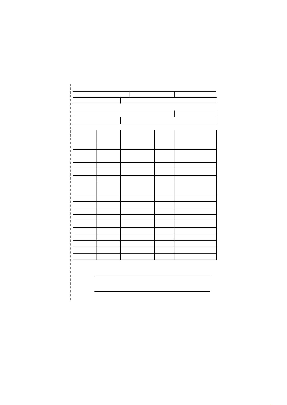
Technical Support/RMA Sheet
Customer/Country: Company: Phone No.:
Contact Person: E-mail Add. :
Model name/Lot Num ber: PCB revision:
BIOS version: O.S./A.S.:
Hardware Mfs. Model name Size: Driver/Utility:
Configuration
CPU
Memory
Brand
Video Card
Audio Card
HDD
CD-ROM /
DVD-ROM
Modem
Network
AMR / CNR
Keyboard
Mouse
Power supply
Other Device
Problem Description:
?
Page 9

When you installing AGP card, please make sure the follow
ing notice is fully understood and practiced. If your AGP
card has "AGP 4X notch"(show below), please make sure
your AGP card is AGP 4X (1.5V).
Do not use AGP 2X card (3.3V) in this motherboard. It will
burn and damage the motherboard due to Intel® 845 chipset
can't support AGP 2X(3.3V).
Example 1: Diamond Vipper V770 golden finger is compatible with 2X/
4X mode AGP slot. It can be switched between AGP 2X (3.3V) or 4X
(1.5V) mode by adjusting the jumper. The factory default for this card is
2X(3.3V). If you install this card in GA-8IRX (or any AGP 4X only)
motherboards without switching the jumper to 4X mode (1.5V), it will
burn the motherboard.
Example 2: ATi Rage 128 Pro (Power Color) & SiS 305 golden finger is
compatible with 2X/4X mode AGP slot, but it supports 2X(3.3V) only. If
you install this card in GA-8IRX (or any AGP 4X only) motherboards, it
will burn the motherboard.
Note : Although Gigabyte's AG32S graphics card is based on ATi Rage
128 Pro chip, the design of AG32S is compliance with AGP 4X (1.5V)
specification. Therefore, AG32S will work fine with Intel 845 / 850 based
motherboards.
Before you install PCI cards, please remove the Dual BIOS
label from PCI slots if there is one.
Page 10

? The author assumes no responsibility for any errors or omissions
that may appear in this document nor does the author make a
commitment to update the information contained herein.
? Third-party brands and names are the property of their respective
owners.
? Please do not remove any labels on motherboard, thismay void the
warranty of this motherboard.
? Due to rapid change in technology, some of the specifications might
be out of date before publication of this booklet.
Page 11

Ausschlager Weg 41, 1F, 20537 Hamburg, Germany
( descript ion of t he apparatus, system, inst allat ion to which it ref ers)
(ref erence t o t he specif ication under which conf ormit y is declared)
in accordance wit h 89/336 EEC-EMC Directive
? EN 55011 Lim its and m et hods of m easurem ent
? EN 55013
? EN 55014 Lim its and m et hods of m easurem ent
? EN 55015 Lim its and m et hods of m easurem ent
? EN 55020
? EN 55022 Lim its and m et hods of m easurem ent
? DIN VDE 0855
? part 10
? part 12
? CE marking
? EN 60065
? EN 60335
of radio disturbance characteristics of
indust rial,scientific and medical (ISM
high f requency equipment
Lim its and m et hods of m easurem ent
of radio disturbance characteristics of
broadcast receivers and associat ed
equipm ent
of radio disturbance characteristics of
household elect rical appliances,
port able tools and sim ilar elect rical
apparat us
of radio disturbance characteristics of
f luorescent lam ps and lum inaries
Im munity from radio int erference of
broadcast receivers and associat ed
equipm ent
of radio disturbance characteristics of
inf ormat ion t echnology equipm ent
Cabled dist ribution system s; Equipment
f or receiving and/or distribution from
sound and t elevision signals
The manufacturer also declares the conformity of above mentioned product
with the actual required safety standards in accordance with LV D 73/ 23 EEC
Saf ety requirem ent s f or m ains operat ed
elect ronic and related apparatus f or
household and sim ilar general use
Saf ety of household and sim ilar
elect rical appliances
(S tamp )
Declaration of Conformity
We, Manuf acturer/Importer
(f ull address)
G.B.T. Technology Trä ding GMbH
declare t hat t he product
Mother Board
GA-8IRX
is in conf ormity with
? EN 61000-3-2*
? EN 60555-2
? EN 61000-3-3* Dist urbances in supply system s cause
? EN 60555-3
? EN 50081-1 Generic em ission st andard Part 1:
? EN 50082-1
? EN 55081-2
? EN 55082-2
? ENV 55104
? EN50091-2
(EC conf ormit y m arking)
? EN 60950
? EN 50091-1
Manufacturer/Importer
Dat e : Oct. 11, 2001
Dist urbances in supply system s cause
by household appliances and sim ilar
elect rical equipment “ Harm onics”
by household appliances and sim ilar
elect rical equipment “ Volt age f luctuations”
Residual com mercial and light indust ry
Generic im munit y st andard Part 1:
Residual com mercial and light indust ry
Generic em ission st andard Part 2:
Indust rial environment
Generic em ission st andard Part 2:
Indust rial environment
lm munit y requirements f or household
appliances t ools and similar apparat us
EMC requirem ents for uninterrupt ible
power syst ems (UPS)
Signat ure:
Nam e:
Ti mmy H u an g
Tim m y Huang
Page 12

DE CLARATION OF CONF ORMITY
Pe r FCC Part 2 Sect ion 2.1077(a)
Responsible Party
Name:
h ereby declares that the product
Con forms to the follo wing specifications:
FCC Part 15, Su b part B, Sectio n 15.107(a) an d Section 15.109
(a),Clas s B Digi tal Device
Supplementary Information:
Th is device co mplies wi th part 15 of the FCC Rules . Operati on is
s ubject to t he follo wing two conditi ons: (1) This device may not
cau se harmful and (2) this device must accept any inference received,
in cluding that may cause undesired operation.
Repres entative Person’s Name:
Address:
Phon e/Fax No:
Product Name:
Model Number:
Sig nature:
G.B.T. INC.
17358 Railroad Street
City of Industry, CA 91 748
(818) 854-9338/ (818) 854-9339
Motherboard
G A-8IRX
ERIC LU
Eric Lu
Date:
Oc t. 11,2001
Page 13

Acronyms
Acronyms Meaning
ACPI Advanced Configuration and Power Interface
APM Advanced Power Management
AGP Accelerated Graphics P ort
AMR Audio Modem Riser
ACR Advanced Communications Riser
BBS BIOS Boot S pecification
BIOS Basic Input / Output System
CPU Central Processing Unit
CMOS Complementary Metal Oxide S em iconductor
CRIMM Continuity RIMM
CNR Comm unicat ion and N etworking Riser
DMA Direct Memory Access
DMI Desktop Management Interface
DIMM Dual Inline Memory Module
DRM Dual Retention Mechanism
DRAM Dynamic Random Access Memory
DDR Double Data Rate
ECP Extended C apabilities P ort
ESCD Extended System Configuration Data
ECC Error Checking and Correcting
EMC Electrom agnetic C ompatibility
EPP Enhanced Parallel P ort
ESD Electrostatic Discharge
FDD Floppy Disk Device
FSB Front Side Bus
HDD Hard Disk Device
IDE Integrated Dual Channel Enhanced
IRQ Interrupt Request
I/O Input / Output
IOAPIC Input Output Advanced P rogramm able Input Controller
ISAIndustry Standard Architecture
to be continued......
Page 14

Acronyms Meaning
LAN Local Area Network
LBA Logical Block Addressing
LED Light Emitting Diode
MHz Megahertz
MIDI Musical Interface Digital Interface
MTH Memory Translator Hub
MPT Memory Protocol Translator
NIC Netw ork Int erface C ard
OS Operating System
OEM Original Equipment M anuf acturer
PAC PCI A.G.P. Controller
POST Power-On Self Test
PCI Peripheral Component Interconnect
RIMM Rambus in-line Memory M odule
SCI Special Circumstance Instructions
SECC Single Edge Contact Cartridge
SRAM Static Random Access Memory
SMP Symmetric Multi-Processing
SMI System M anagem ent Interrupt
USB Universal Serial Bus
VID Voltage ID
Page 15
?
Technical Support/RMA Sheet
Customer/Country: Company: Phone No.:
Contact Person: E-mail Add. :
Model name/Lot Num ber: PCB revision:
BIOS version: O.S./A.S.:
Hardware Mfs. Model name Size: Driver/Utility:
Configuration
CPU
Memory
Brand
Video Card
Audio Card
HDD
CD-ROM /
DVD-ROM
Modem
Network
AMR / CNR
Keyboard
Mouse
Power supply
Other Device
Problem Description:
?
Page 16

English
Item Checklist ..................................................................................3
WARNING! ......................................................................................3
Chapter 1 Introduction .......................................................................4
Chapter 2 Hardware Installation Process ............................................7
Table of Content
Features Summary ................................................................................................ 4
GA-8IRX Motherboard Layout ............................................................................. 6
Step 1: Install the Central Processing Unit (CPU) ............................................ 8
Step 1-1 : CPU Installation . .. .. .. .. .. .. .. .. .. .. .. .. .. .. .. .. .. .. .. .. .. .. .. .. .. .. .. .. .. .. .. .. .. .. .. .. .. .. 8
Step 1-2 : CPU Heat Sink Installation .. .. .. .. .. .. .. .. .. .. .. .. .. .. .. .. .. .. .. .. .. .. .. .. .. .. .. .. .. .. .. .. 9
Step 2: Install memory modules ........................................................................ 10
Step 3: Install expansion cards .......................................................................... 11
Step 4: Connect ribbon cables, cabinet wires, and power supply ............... 12
Step 4-1 : I/O Back Panel Introduction............................................................. 12
Step 4-2 : Connectors Introduction . .. .. .. .. .. .. .. .. .. .. .. .. .. .. .. .. .. .. .. .. .. .. .. .. .. .. .. .. .. .. .. .. 14
Chapter 3 BIOS Setup .................................................................... 20
The Main Menu ..................................................................................................... 20
Select Language .................................................................................................. 20
Load Optimized Default ...................................................................................... 22
Save & Exit Setup ................................................................................................ 23
Chapter 4 Driver Installation ............................................................ 24
- 2 -GA-8IRX Motherboard
Page 17
Item Checklist
? The GA-8IRX motherboard
? IDE cable x 1/ Floppy cable x 1
? CD for motherboard driver & utility (IUCD)
? GA-8IRX user’s manual
? Quick PC Installation Guide
? USB Cable x 1
WARNING!
Computer motherboards and expansion cards contain very delicate Integrated Circuit (IC) chips. To
protect them against damage from static electricity, y ou should follow some precautions whenever
you work on your computer.
1. Unplug your computer when working on the inside.
2. Use a grounded wrist strap before handling computer components. If y ou do not hav e
one, touch both of y our hands to a safely grounded object or to a metal object, such as
the power supply case.
3. Hold components by the edges and try not touch the IC chips, leads or connectors, or
other components.
4. Place components on a grounded antistatic pad or on the bag that came with the
components whenev er the components are separated from the sy stem.
5. Ensure that the ATX power supply is switched off before you plug in or remov e the ATX
ower connector on the motherboard.
English
Installing the motherboard to the chassis…
If the motherboard has mounting holes, but they don’t line up with the holes on the base and
there are no slots to attach the spacers, do not become alarmed y ou can still attach the spacers to
the mounting holes. Just cut the bottom portion of the spacers (the spacer may be a little hard to
cut off, so be careful of your hands). In this way y ou can still attach the motherboard to the base
without worrying about short circuits. Sometimes you may need to use the plastic springs to isolate
the screw from the motherboard PCB surface, because the circuit wire may be near by the hole. Be
careful, don’t let the screw contact any printed circuit write or parts on the PC B tha t are near the
fix ing hole, otherwise it may damage the board or cause board malfunctioning.
- 3 -
Introduction
Page 18

Chapter 1 Introduction
Features Summary
English
Form Factor ? 30.5cm x 22.8cm ATX size form factor, 4 layers PCB.
CPU ? Socket 478 for Intel® Micro FC-PGA2 Pentium® 4 processor
Chipset ? Chipset 82845 HOST/AGP/Controller
Memory ? 3 184-pin DDR DIMM sockets
I/O Control ? IT8712
Slots ? 1 CNR(Communication and Networking Riser) Slot
On-Board IDE ? An IDE controller on the Intel 82801BA PCI chipset
On-Board Peripherals ? 1 Floppy port supports 2 FDD with 360K, 720K,1.2M, 1.44M
Hardware Monitor ? CPU/Power/System Fan Revolution detect
?? Support Intel ® Pentium ® 4 (Northwood, 0.13um) processor
? Intel Pentium®4 400M Hz FSB
? 2nd cache depend on CPU
? 82801BA(ICH2) I/O Controller Hub
? Supports PC1600 DDR or PC2100 DDR DIMM
? Supports up to 2GB DRAM (Max)
? Supports only 2.5V DDR DIMM
? Supports 64bit ECC type DRAM integrity mode
? 1 AGP slot 4X (1.5V) device support
? 6 PCI slot supports 33MHz & PCI 2.2 compliant
provides IDE HDD/CD-ROM with PIO, Bus Master (Ultra
DMA33/ATA66/ATA100) operation modes.
? Can connect up to four IDE devices
and 2.88M bytes.
? 1 Parallel port supports Normal/EPP/ECP mode
? 2 Serial ports (COMA&COMB)
? 4 USB ports (Rear USB x 2, Front USB x 2)
? 1 SC R connector
? 1 IrDA connector for IR
? CPU/Power/System Fan Control
? CPU Overheat Warning
? System Voltage Detect
to be continued......
- 4 -GA-8IRX Motherboard
Page 19

On-Board Sound ? Creative CT5880 Sound Chipset + Sigmatel 9708T CODEC
? Line In/Line Out/Mic In/CD In/AUX_IN/Game Port
PS/2 Connector ? PS/2 Keyboard interface and PS/2 Mouse interface
BIOS ? Licensed AWARD BIOS, 4M bit x 2 FWH
? Supports Dual BIOS
Additional Features ? PS/2 Keyboard pow er on by passw ord
? PS/2 Mouse power on
? External Modem w ake up
? STR(Suspend-To-RAM)
? Wake on LAN
? AC Recovery
? USB KB/Mouse wake up from S3
? Supports @BIOS
? Supports EasyTuneIII
? Supports Multi Language
Special Features ? Over Voltage (DDR / AGP)
? Over Clock (CPU / DDR)
English
Please set the CPU host frequency in accordance with your processor’s specifications.
We don’t recommend you to set the system bus frequency over the CPU’s specification
because these specific bus frequencies are not the standard specifications for C PU,
chipset and most of the peripherals. Whether your system can run under these specific
bus frequencies properly will depend on your hardware configurations, including CPU,
Chipsets,SDRAM,Cards… .etc.
- 5 -
Introduction
Page 20
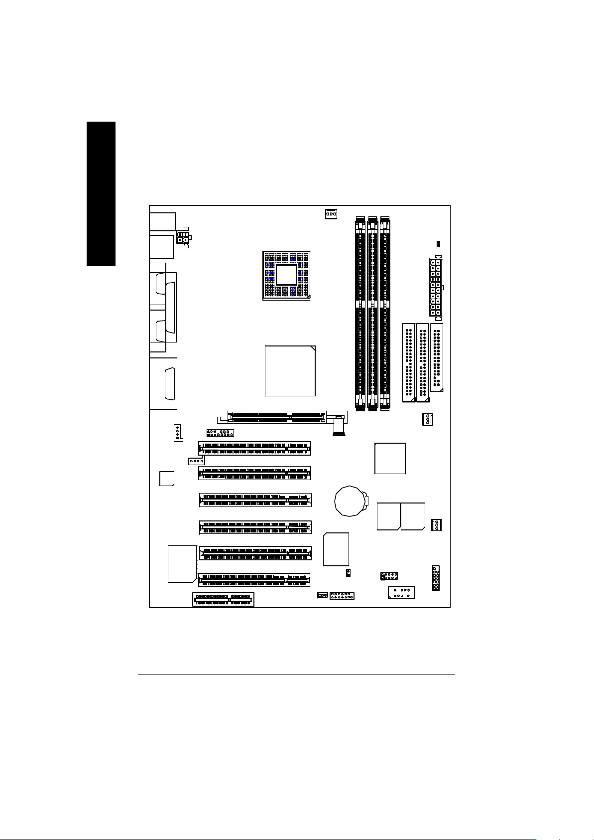
GA-8IRX Motherboard Layout
English
KB_ MS
LINE_OUTMIC_IN
LINE_IN
AC97
USB
COMACOMB
LPT1
GAME
CD_IN
AUX_12V
AUX_IN
P4 Titan-DDR
F_AUDIO
SOCKET478
GA-8IRX
Brookdale
AG P
CPU_FAN
PCI1
PCI2
PCI3
PCI4
BATT ERY
DDR1
DDR2
ICH2
MAIN
BI OS
DDR3
IDE2
BAC KUP
BIOS
STR/DIMM_LED
ATX
FLOPPY
IDE1
PWR_FAN
SY S
FAN
CT5880
CNR
IT8712
PCI5
PCI6
WOL
SCR
IR
CI
FRONT USB
F_PANEL
- 6 -GA-8IRX Motherboard
Page 21
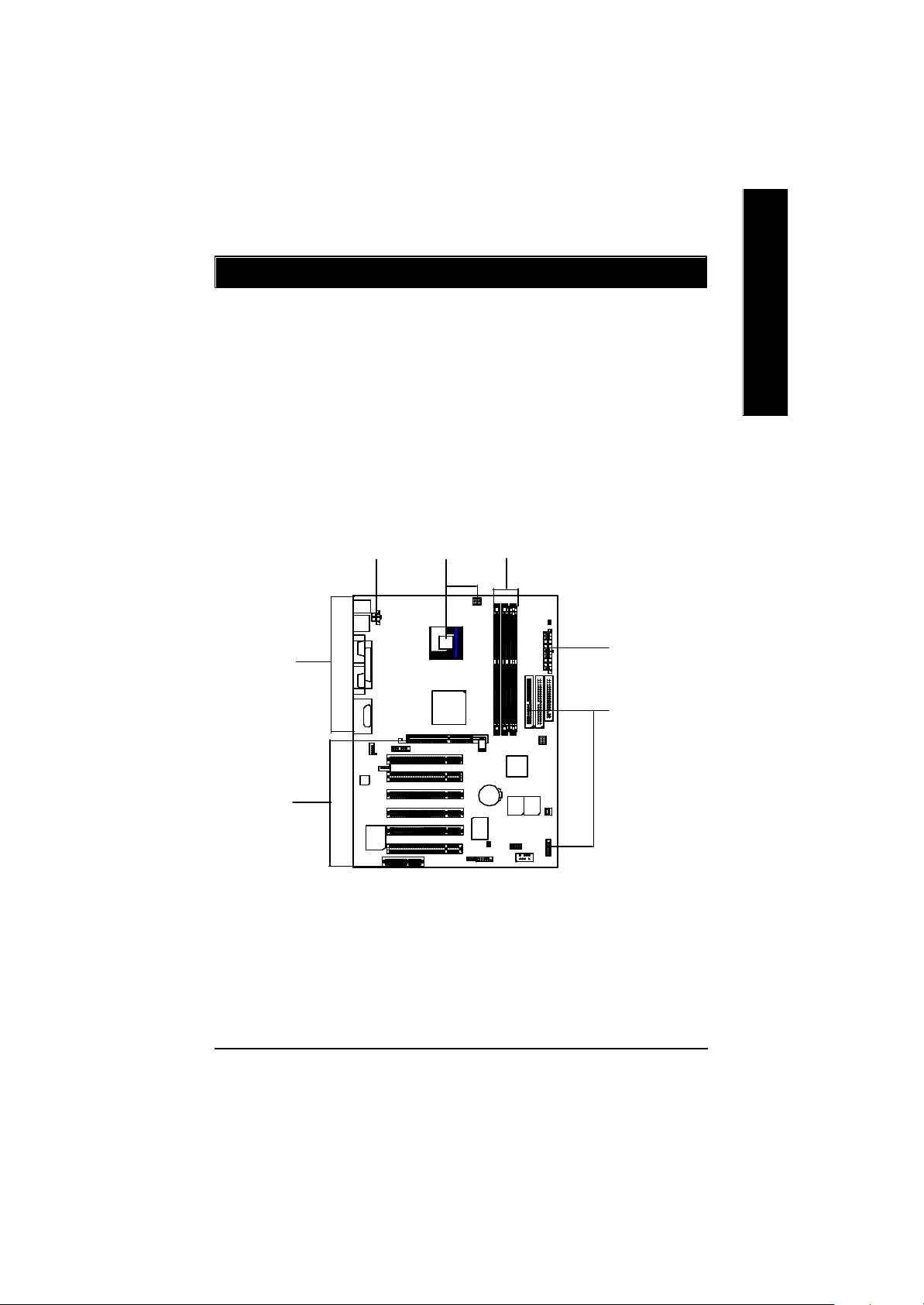
Chapter 2 Hardware Installation Process
To set up your computer, you must complete the following setps:
Step 1- Install the Centr al Processing Unit (CPU)
Step 2- Install memory modules
Step 3- Install expansion cards
Step 4- Connect ribbon cables, cabinet wires, and power supply
Step 5- Setup BIOS software
Step 6- Install supporting software tools
English
Step 4
Step3
Step4
Step1
Step 2
Step 4
Step 4
- 7 - Hardware Installation Process
Page 22

Step 1: Install the Central Processing Unit (CPU)
Step 1-1 CPU Installation
English
Pin1 indicator
CPU Top View CPU Bottom View
Socket Actuation Lever
1. Pull up the CPU socket lever
and up to 90-degree angle.
3. Press down the CPU socket
lever and finish CPU installation.
? Please make sure the CPU type is supported by the motherboard.
Pin1indicator
Pin1 indicator
2. Locate Pin 1 in the socket and look
for a (golden) cut edge on the CPU
upper corner. Then insert the CPU
into the socket.
? If you do not match the CPU socket Pin 1 and CPU cut edge well, it will cause
improper installation. Please change the insert orientation.
- 8 -GA-8IRX Motherboard
Page 23

Step 1-2 : CPU Heat Sink Installation
English
1. Hook one end of the cooler
bracket to the C PU socket first.
? Please use Intel approved cooling fan.
? We recommend you to apply the thermal tape to provide better heat conduction between
your CPU and heatsink.
(The CPU cooling fan might stick to the CPU due to the hardening of the thermal paste.
During this condition if you try to remove the cooling fan, you might pull the processor out
of the CPU socket alone with the cooling fan, and might damage the processor. To avoid
this from happening, we suggest you to either use thermal tape instead of thermal paste, or
remove the cooling fan with extreme caution.)
? Make sure the CPU fan power cable is plugged in to the CPU fan connector, this completes
the installation.
? Please refer to CPU heat sink user’s manual for more detail installationprocedure.
2. Hook the other end of the
cooler bracket to the CPU
socket.
- 9 - Hardware Installation Process
Page 24

Step 2: Install memory modules
The motherboard has 3 dual inline memory module (DIM M) s ock ets, b ut it can only support a
maximum of 4 banks of DDR memory. DDR slot 1 uses 2 banks, DDR slot 2&3 share the remaining
English
2 banks. Please refer to the follow ing tables for pos sibl e m emor y c onfigura tions s upp orted. The
BIOS will automatically detects memory type and size. To install the memory module, just push it
vertically into the DIMM Slot .The DIM M mo dule can only fit in one direction due to the notch.
Memory size can vary between sockets.
Total Memory Sizes With Unbuffered DDR DIMM
Dev ices used on DIMM 1 DIMM x 64 / x 72 2 DIMMs x 64 / x 72 3 DIMMs x 64 / x 72
64 Mbit (2Mx 8x 4 banks) 128 MBytes 256 MBytes 256 MBytes
64 Mbit (1Mx 16x 4 banks) 32 MBy tes 64 MBy tes 96 MBy tes
128 Mbit(4Mx 8x 4 banks) 256 MBytes 512 MBytes 512 MBytes
128 Mbit(2Mx 16x 4 banks) 64 MBy tes 128 MBytes 196 MBytes
256 Mbit(8Mx 8x 4 banks) 512 MBytes 1 GBy tes 1 GBy tes
256 Mbit(4Mx 16x 4 banks) 128 MBytes 256 MBytes 384 MBytes
512 Mbit(16Mx 8x 4 banks) 1 GBy tes 2 GBy tes 2 GBy tes
512 Mbit(8Mx 16x 4 banks) 256 MBytes 512 MBytes 768 MBytes
Notes: Double-sided x 16 DDR memory dev ic es are not support by Intel 845 chipset.
D:Double Sided DIMM S:Single Sided DIMM
X:Not Use
DDR1 DDR2 DDR3
S S S
D S S
D D X
D X D
S D X
S X D
DDR
1. The DIMM slot has a notch, so the
DIMMmemory module can only fit in one direction.
2. Insert the DIMM memory module verticallyinto the
DIMM slot. Then push it down.
3. Close the plastic clip at both edges of theDIMM slots
to lock the DIMM module.
Reverse the installation steps when you wish to
remove the DIMM module.
? When STR/DIMM LED is ON, do not install/remove DIMM from socket.
? Please note that the DIMM module can only fit in one direction due to
the two notches. Wrong orientation will cause improper installation.
Please change the insert orientation.
- 10 -GA-8IRX Motherboard
Page 25

Step 3: Install expansion cards
1. Read the related ex pansion card’s instruction document before install the expansion card into
the computer.
2. Remove your computer’s chassis cover, screws and slot bracket from the computer.
3. Press the expansion card firmly into expansion slot in motherboard.
4. Be sure the metal contacts on the card are indeed seated in the slot.
5. Replace the screw to secure the slot bracket of the expansion card.
6. Replace your computer’s chassis cover.
7. Power on the computer, if necessary, setup BIOS utility of expansion card from BIOS.
8. Install related driver from the operating system.
Please carefully pull out the small whitedraw able bar at the end of th e AGP slot
when you try to install/ Uninstall the AGP
AGP Card
card. Please align the AGP card to the
onboard AGP slot and press firmly dow n on
the slot .M ake sure your AGP card is locked
by the small white- drawable bar.
English
Issues To Beware Of When Installing CNR
Please use standard CNR card like the one in order to avoid mechanical problem.
Standard CNR Card
- 11 - Hardware Installation Process
Page 26

Step 4: Connect ribbon cables, cabinet wires, and power
supply
English
Step 4-1 : I/O Back Panel Introduction
?
?
?
? PS/2 Keyboard and PS/2 Mouse Connector
PS/2 Mouse Connector
(6 pin Female)
PS/2 Keyboard Connector
(6 pin Female)
? USB Connector
USB 0
USB 1
?This connector supports standard PS/2
keyboard and PS/2 mouse.
?Before you connect your device(s) into USB
connector(s), please make sure your device(s)
such as USB keyboard, mouse, scanner, zip,
speaker..etc. Hav e a standard USB interface.
Also make sure your OS (Win 95 with USB
supplement, Win98, Windows 2000, Windows
ME, WinNT with SP 6) supports USB controller.
If your OS does not support USB controller,
please contact OS vendor for possible patch or
driver upgrade. For more information please
contact your OS or device(s) vendors.
?
?
- 12 -GA-8IRX Motherboard
Page 27

? Parallel Port and Serial Ports (COMA/COMB)
?This connector supports 2 standard COM ports
Parallel Port
(25 pin Female)
COMA COMB
Serial Ports (9 pin Male)
and 1 Parallel port. Dev ice like printer can be
connected to Parallel port ; mouse and modem
etc can be connected to Serial ports.
English
? Game /MIDI Ports
Joystick/ MIDI (15 pin Female)
? Audio Connectors
MIC InLine Out
Line In
?This connector supports joystick, M IDI keyboard
and other relate audio devices.
? After install onboard audio driver, you may connect
speaker to Line Out jack, micro phone to MIC In jack.
Device like C D-ROM , w alkman etc can be connected
to Line-In jack.
Please note: Line Out 1: Line Out or SPDIF (The SPDIF
output is capable of providing digital audio to external
speakers or compressed AC3 data to an external Dolby
digital decoder). To enable SPDIF, simply insert SPDIF
connector into Line Out1. Line Out1 will become SPDIF
Out automatically.
To enable Four Speaker (for Creative 5880 audio only),
and Line In will become Line Out2 to support second
pair of stereo speakers.
If you want to realize the “Four Speaker & SPDIF
“ setup information in detail, please download
this manual from Gigabyte web
http://www.gigabyte.com.tw.
- 13 - Hardware Installation Process
Page 28

Step 4-2 :Connectors Introduction
English
A
R
Q
P
O
B
C
D
E
F
N
M
J
L
A) CPU_FAN J) IR/CIR
B) STR/DIMM_LED K) SCR
C) ATX L) WOL
D) FLOPPY M) CI
E) IDE1/IDE2 N) BAT
F) PWR_FAN O) AUX_IN
G) SYS_FAN P) CD_IN
H) F_PANEL Q) F_AUDIO
I) FRONT_USB R) AUX_12V
IK
G
H
- 14 -GA-8IRX Motherboard
Page 29

R) AUX_12V( +12V Power Connector)
123
GND
GND
+12V
+12V
4
? This connector (ATX +12V) is
used only for CPU Core Voltage.
English
A) CPU_FAN (CPU Fan Connector)
Sense
1
CPU_FAN
+12V/Control
GND
F) PWR_FAN (Power Fan Connector)
1
GND
+12V/Control
Sense
C) ATX (ATX Power Connector)
20
5V SB (Stand by +5V)
+12V
Power Good
GND
VCC
GND
VCC
GND
3.3V
3.3V
1
? Please note, a proper installation of the CPU
cooler is essential to prevent the CPU from
running under abnormal condition or
damaged by overheating.The CPU fan
connector supports Max. current up to 600mA .
G) SYS_FAN (System Fan Connector)
Sense
1
+12V/Control
GND
?AC power cord should only be connected to
your power supply unit after ATX power
cable and other related dev ices are firmly
connected to the mainboard.
VCC
VCC
-5V
GND
GND
GND
PS-ON(Soft On/Off)
GND
-12V
3.3V
- 15 - Hardware Installation Process
Page 30

E ) IDE1 / IDE2 Connector(Primary/Secondary]
English
? Important Notice:
Please connect first harddisk to IDE1
and connect CDROM to IDE2.
1
IDE2
1
IDE1
D) FLOPPY (Floppy Connector)
1
O ) AUX_IN ( AUX In Connector)
AUX-R
AUX-L
GND
AUX_IN
1
P) CD_IN (CD Audio Line In Connector)
CD-R
GND
1
CD-L
L) WOL(Wake on LAN)
1
+5V SB
GND
Signal
- 16 -GA-8IRX Motherboard
Page 31

I) FRONT_USB (Front USB Connector)
GND
NC
USB D3+
USB D3-
Power
1
NC
USB D2-
USB D2+
GND
Power
? Be careful with the polarity of the front
panel USB connector. Check the pin
assignment while you connect the front
panel USB cable. Please contact your
nearest dealer for optional front panel
USB cable.
English
Q) F_AUDIO (F_AUDIO Connector)
There are two types of front audio
connector, please refer to the tables
below before you install.
Incase speaker (L)
GND
Rear Audio (R)
GND
GND
Rear Audio (L)
1
GND
GND
Incase speaker (R)
GND
+12V
MIC
Front Audio (R)
Front Audio (L)
? If y ou want to use type 1-Front Audio
connector, y ou must remove 11-12, 13-14
Jumper.If y ou want to use type 2-Front Audio
connector, you must remove 3-4, 5-6 Jumper.
In order to utilize the front audio header, your
chassis must hav e front audio connector. Also
please make sure the pin assigment on the cable
is the same as the pin assigment on the MB
header. To find out if the chassis you are buy ing
support front audio connector, please contact your
dealer
GND
Rear Audio (L)
Rear Audio (R)
1
MIC
GND
Type2
Type1
Front Audio (R)
Front Audio (L)
- 17 - Hardware Installation Process
Page 32
B) STR/DIMM_LED
English
STR/DIMM LED
? Do not remove memory modules while
DIMM LED is on. It might cause short or
other unex pected damages due to the
2.5V stand by voltage. Remove memory
modules only when STR function is
disabled by jumper and AC Pow er cord is
disconnected.
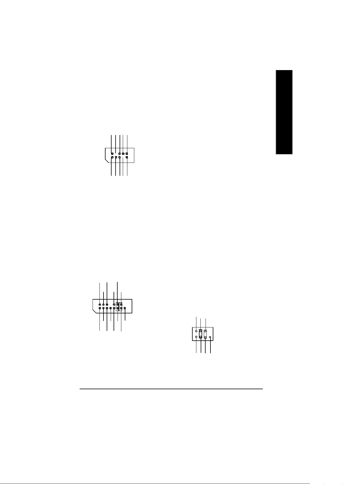
K) SCR (Smart Card Reader Header)
NCNCDATA
NC
1
VCC
VCC
DATA
Clock
DATA
NC
DATA
GND
NC
NC
J) IR/CIR (IR/CIR )
NC
VCC
GND
IRRX
GND
NC
IRTX
CIRRX
1
NC
VCC
M) CI (CASE OPEN)
? This MB supports smart card reader. To
enable smart card reader function an optional
smart card reader box is required. Please
contact your autherized distributor.
? Make sure the pin 1 on the IR device is
aling w ith pin one the co nnec tor. To
enable the IR/CIR function on the board,
you are required to purchase an option IR/
CIR module. For detail information please
contact y our autherized Giga-Byte
distributor.
To use IR function only, please connect IR
module to Pin1 to Pin5.
? This 2 pin connector allows y our system to
enable or disable the system alarm if the sys
tem case begin remove.
GND
1
Signal
- 18 -GA-8IRX Motherboard
Page 33

H) F_PANEL (2x7 pins jumper)
13
RST-
2 14
1
1
PW+
PW-
PD+
PD_GPD_Y-
HD+
Pin 2: LED cathode(-)
Pin 2- Pin 3: NC
Pin 4: Data(-)
Close: Reset H ardware Sy stem
Pin 2: LED cathode(-)
Pin 3: LED cathode(-)
Close: Power On/Off
RST+
SPK+
1
SPK-
HD-
HD (IDE Hard Disk Active LED) Pin 1: LED anode(+)
SPK (Speaker Connector) Pin 1: VCC(+)
RST (Reset Sw itch) Open: Normal Operation
PD+/PD_G-/PD_Y-(Power LED) Pin 1: LED anode(+)
PW (Soft Power Connector) Open: Normal Operation
English
? Please connect the power LED, PC speaker, reset switch and power switch etc of your chassis
front panel to the F_PANEL connector according to the pin assignment above.
N) BAT (Battery)
? Danger of explosion if battery is incorrectly
+
replaced.
? Replace only with the same or equivalent
type recommended by the manufacturer.
? Dispose of used batteries according to the
manufacturer’s instructions.
- 19 - Hardware Installation Process
CAUTION
Page 34
Chapter 3 BIOS Setup
BIOS Setup is an overview of the BIOS Setup Program. The program that allows users to modify
English
the basic system configuration. This type of information is stored in battery-backed CMOS RAM so
that it retains the Setup information when the pow er is turned o ff.
ENTERING SETUP
After power on the computer, pressing <Del> immediately during POST (Power On Self Test) it will allow y ou to
enter standard BIOS CMOS SETUP.
If y ou require more adv anced BIOS settings, please go to “ Adv anc ed BIOS” setting menu. To enter Adv anced
BIOS setting menu, press “Ctrl+F1” key on the BIOS screen.
GETTING HELP
The on-line description of the highlighted setup function is display ed at the bottom of the screen.
Press F1 to pop up a small help window that describes the appropriate key s to use and the possible selections
for the highlighted item. To ex it the Help Window press <Esc>.
The Main Menu
Once y ou enter Award BIOS CMOS Setup Utility, the Main Menu will appear on the screen. The Main Menu
allows y ou to select from eight setup functions and two ex it choices. Use arrow key s to selec t among the items
and press <Enter> to accept or enter the sub-menu.
Dual BIOS / Q-Flash Utility
After power on the computer, pressing <Del> immediately during POST (Power On Self Test) it will allow y ou
to enter Award BIOS CMOS SETUP, then press <F8> to enter DualBIOS/Q-Flash utility. If you want to
detail information for “DualBIOS/Q-Flash Utility “, please download this manual from Gigabyte web
http://www.gigabyte.com.tw.
Select L anguage
Japanese, French, Spanish, Germany, Simplified Chinese, Traditional Chinese.
Main Menu
Status Page Setup Menu / Option Page Setup Menu
You can press <F3> to select multi language. There are 7 languages av ailable, including English,
CMOS Set up Utility-Cop yright (C) 198 4-2002 Award S oftware
?Standard CMOS Features Select Language
?Advanced BIOS Features Load Fail-Safe Defaults
?Integrated Peripherals Load Optimized Defaults
?Power Management Setup Set Supervisor Password
?PnP/PCI Configurations Set User Password
?PC Health Status Save & Exit Setup
?Frequency/Voltage Control Exit Without Saving
Top Performance
- 20 -GA-8IRX Motherboard
u
Page 35

? Standard CMOS Features
This setup page includes all the items in standard compatible BIOS.
? Advanced BIOS Features
This setup page includes all the items of Award special enhanced features.
? Advanced Chipset Features
This setup page includes all the items of chipset special features.
We would not suggest you change the chipset default setting unless you really
need it.
? Integrated Peripherals
This setup page includes all onboard peripherals.
We would not suggest you change the default setting unless you really need it.
For power End-User use only.
? Power Management Setup
This setup page includes all the items of Green function features.
We would not suggest you change the default setting unless you really need it.
For power End-User use only.
? PnP/PCI Configurations
This setup page includes all the configurations of PCI & PnP ISA resources.
We would not suggest you change the default setting unless you really need it.
For power End-User use only.
? PC Health Status
This setup page is the System auto detect Temperature, voltage, fan, speed.
? Frequency/Voltage Control
This setup page is control CPU’s clock and frequency ratio.
For power End-User use only.
? Select Language
This setup page is select multi language.
? Load Fail-Safe Defaults
Fail-Safe Defaults indicates the v alue of the system parameters which the sy stem w ould
be in safe configuration.
? Load Optimized Defaults
Optimized Defaults indicates the value of the system parameters which the system w ould
be in best performance configuration.
- 21 - BIOS Setup
English
Page 36

? Set Supervisor password
English
? Set User password
? Save & Exit Setup
? Exit Without Saving
Load Optimiz ed Default
Change, set, or disable password. It allows you to limit access to the sy stem and Setup,
or just to Setup.
Change, set, or disable password. It allows you to limit access to the system.
Save CMOS value settings to CMOS and exit setup.
Abandon all CMOS value changes and exit setup.
CMOS Set up Utility-Cop yright (C) 198 4-2002 Award S oftware
?Standard CMOS Features Select Language
?Advanced BIOS Features Load Fail-Safe Defaults
?Integrated Peripherals Load Optimized Defaults
?Power Management Setup Set Supervisor Password
?PnP/PCI Configurations Set User Password
?PC Health Status Save & Exit Setup
?Frequency/Voltage Control Exit Without Saving
Top Performance
Load O ptimized Defaults? (Y/N)?Y
? Load Optimized Defaults
Selecting this field loads the factory defaults for BIOS and Chipset Features which the
system automatically detects.
To Load Optimized, move cursor, by pressing the arrow keys on the keyboard ,to highlight
the optimized default and press enter key then press "Y" if you decide to load this option.
- 22 -GA-8IRX Motherboard
Page 37
Save & Exit Setup
CMOS Set up Utility-Cop yright (C) 198 4-2002 Award S oftware
?Standard CMOS Features Select Language
?Advanced BIOS Features Load Fail-Safe Defaults
?Integrated Peripherals Load Optimized Defaults
?Power Management Setup Set Supervisor Password
?PnP/PCI Configurations Set User Password
?PC Health Status Save & Exit Setup
?Frequency/Voltage Control Exit Without Saving
Top Performance
? To save exit the BIOS setting screen press F10, and press "Y" if
you want to save setting. By typing "N" or "ESC" will take you
back to setup screen.
If you want to realize the BIOS setup information in detail, please down-
load this manual from Gigabyte web http://www.gigabyte.com.tw.
SAVE to CMOS and EXIT (Y/N)?Y
English
- 23 - BIOS Setup
Page 38

Revision History
Chapter 4 Driver Intallation
Picture below are shown in Windows ME (IUCD driver version 1.9)
English
Insert the driver CD-title that came with your motherboard into your C D-ROM driv er, the d river
CD-title will auto start and show the installation guide. If not, please double click the CD-ROM
device icon in "M y computer", and execute the setup.exe.
A. Installing Intel 845 Chipset Driver
Please install this driver as the first priority .
this item installs the chipset driv er utility that
enableds Plug-n-Plag INF support for Intel
chipset component.
B. Installing Sound Driver
Click this item to install sound driv er.
A: Intel 845 Chipset Driver Installation
Follow the setup that showing on the scween to install the Utility.
A-1. Windows 9x/ME/2000/XP INF Update Utility
Click "Windows 9x/ME/2000/XP INF Update Utility"
item.
B: Sound Driver Installation
Revision History
1. 9
Press "Audio" icon.
A-2. Intel Ultra ATA Storage Driver
Click "Intel Ultra ATA Storage Driver"item.
1.Click "C reativ e C T5880 Sound Driv er"
item.
- 24 -GA-8IRX Motherboard
Page 39

GA-8IRX
P4 Titan DDR Motherboard
USER’S MANUAL
Pentium®4 Processor Motherboard
Rev. 2.0 Third Edition
12M D-8IRX-2003
Page 40

English
Item Checklist ..................................................................................3
WARNING! ......................................................................................3
Chapter 1 Introduction .......................................................................4
Chapter 2 Hardware Installation Process ............................................7
Table of Content
Features Summary ................................................................................................ 4
GA-8IRX Motherboard Layout ............................................................................. 6
Step 1: Install the Central Processing Unit (CPU) ............................................ 8
Step 1-1 : CPU Installation . .. .. .. .. .. .. .. .. .. .. .. .. .. .. .. .. .. .. .. .. .. .. .. .. .. .. .. .. .. .. .. .. .. .. .. .. .. .. 8
Step 1-2 : CPU Heat Sink Installation .. .. .. .. .. .. .. .. .. .. .. .. .. .. .. .. .. .. .. .. .. .. .. .. .. .. .. .. .. .. .. .. 9
Step 2: Install memory modules ........................................................................ 10
Step 3: Install expansion cards .......................................................................... 11
Step 4: Connect ribbon cables, cabinet wires, and power supply ............... 12
Step 4-1 : I/O Back Panel Introduction............................................................. 12
Step 4-2 : Connectors Introduction . .. .. .. .. .. .. .. .. .. .. .. .. .. .. .. .. .. .. .. .. .. .. .. .. .. .. .. .. .. .. .. .. 14
Chapter 3 BIOS Setup .................................................................... 20
The Main Menu ..................................................................................................... 20
Select Language .................................................................................................. 20
Load Optimized Default ...................................................................................... 22
Save & Exit Setup ................................................................................................ 23
Chapter 4 Driver Installation ............................................................ 24
- 2 -GA-8IRX Motherboard
Page 41

Item Checklist
? The GA-8IRX motherboard
? IDE cable x 1/ Floppy cable x 1
? CD for motherboard driver & utility (IUCD)
? GA-8IRX user’s manual
? Quick PC Installation Guide
? USB Cable x 1
WARNING!
Computer motherboards and expansion cards contain very delicate Integrated Circuit (IC) chips. To
protect them against damage from static electricity, y ou should follow some precautions whenever
you work on your computer.
1. Unplug your computer when working on the inside.
2. Use a grounded wrist strap before handling computer components. If y ou do not hav e
one, touch both of y our hands to a safely grounded object or to a metal object, such as
the power supply case.
3. Hold components by the edges and try not touch the IC chips, leads or connectors, or
other components.
4. Place components on a grounded antistatic pad or on the bag that came with the
components whenev er the components are separated from the sy stem.
5. Ensure that the ATX power supply is switched off before you plug in or remov e the ATX
ower connector on the motherboard.
English
Installing the motherboard to the chassis…
If the motherboard has mounting holes, but they don’t line up with the holes on the base and
there are no slots to attach the spacers, do not become alarmed y ou can still attach the spacers to
the mounting holes. Just cut the bottom portion of the spacers (the spacer may be a little hard to
cut off, so be careful of your hands). In this way y ou can still attach the motherboard to the base
without worrying about short circuits. Sometimes you may need to use the plastic springs to isolate
the screw from the motherboard PCB surface, because the circuit wire may be near by the hole. Be
careful, don’t let the screw contact any printed circuit write or parts on the PC B tha t are near the
fix ing hole, otherwise it may damage the board or cause board malfunctioning.
- 3 -
Introduction
Page 42

Chapter 1 Introduction
Features Summary
English
Form Factor ? 30.5cm x 22.8cm ATX size form factor, 4 layers PCB.
CPU ? Socket 478 for Intel® Micro FC-PGA2 Pentium® 4 processor
Chipset ? Chipset 82845 HOST/AGP/Controller
Memory ? 3 184-pin DDR DIMM sockets
I/O Control ? IT8712
Slots ? 1 CNR(Communication and Networking Riser) Slot
On-Board IDE ? An IDE controller on the Intel 82801BA PCI chipset
On-Board Peripherals ? 1 Floppy port supports 2 FDD with 360K, 720K,1.2M, 1.44M
Hardware Monitor ? CPU/Power/System Fan Revolution detect
?? Support Intel ® Pentium ® 4 (Northwood, 0.13um) processor
? Intel Pentium®4 400M Hz FSB
? 2nd cache depend on CPU
? 82801BA(ICH2) I/O Controller Hub
? Supports PC1600 DDR or PC2100 DDR DIMM
? Supports up to 2GB DRAM (Max)
? Supports only 2.5V DDR DIMM
? Supports 64bit ECC type DRAM integrity mode
? 1 AGP slot 4X (1.5V) device support
? 6 PCI slot supports 33MHz & PCI 2.2 compliant
provides IDE HDD/CD-ROM with PIO, Bus Master (Ultra
DMA33/ATA66/ATA100) operation modes.
? Can connect up to four IDE devices
and 2.88M bytes.
? 1 Parallel port supports Normal/EPP/ECP mode
? 2 Serial ports (COMA&COMB)
? 4 USB ports (Rear USB x 2, Front USB x 2)
? 1 SC R connector
? 1 IrDA connector for IR
? CPU/Power/System Fan Control
? CPU Overheat Warning
? System Voltage Detect
to be continued......
- 4 -GA-8IRX Motherboard
Page 43

On-Board Sound ? Creative CT5880 Sound Chipset + Sigmatel 9708T CODEC
? Line In/Line Out/Mic In/CD In/AUX_IN/Game Port
PS/2 Connector ? PS/2 Keyboard interface and PS/2 Mouse interface
BIOS ? Licensed AWARD BIOS, 4M bit x 2 FWH
? Supports Dual BIOS
Additional Features ? PS/2 Keyboard pow er on by passw ord
? PS/2 Mouse power on
? External Modem w ake up
? STR(Suspend-To-RAM)
? Wake on LAN
? AC Recovery
? USB KB/Mouse wake up from S3
? Supports @BIOS
? Supports EasyTuneIII
? Supports Multi Language
Special Features ? Over Voltage (DDR / AGP)
? Over Clock (CPU / DDR)
English
Please set the CPU host frequency in accordance with your processor’s specifications.
We don’t recommend you to set the system bus frequency over the CPU’s specification
because these specific bus frequencies are not the standard specifications for C PU,
chipset and most of the peripherals. Whether your system can run under these specific
bus frequencies properly will depend on your hardware configurations, including CPU,
Chipsets,SDRAM,Cards… .etc.
- 5 -
Introduction
Page 44

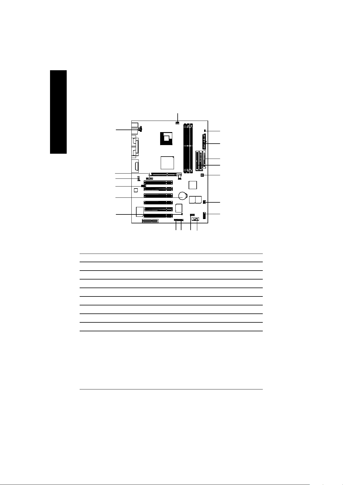
GA-8IRX Motherboard Layout
English
KB_ MS
LINE_OUTMIC_IN
LINE_IN
AC97
USB
COMACOMB
LPT1
GAME
CD_IN
AUX_12V
AUX_IN
P4 Titan-DDR
F_AUDIO
SOCKET478
GA-8IRX
Brookdale
AG P
CPU_FAN
PCI1
PCI2
PCI3
PCI4
BATT ERY
DDR1
DDR2
ICH2
MAIN
BI OS
DDR3
IDE2
BAC KUP
BIOS
STR/DIMM_LED
ATX
FLOPPY
IDE1
PWR_FAN
SY S
FAN
CT5880
CNR
IT8712
PCI5
PCI6
WOL
SCR
IR
CI
FRONT USB
F_PANEL
- 6 -GA-8IRX Motherboard
Page 45

Chapter 2 Hardware Installation Process
To set up your computer, you must complete the following setps:
Step 1- Install the Centr al Processing Unit (CPU)
Step 2- Install memory modules
Step 3- Install expansion cards
Step 4- Connect ribbon cables, cabinet wires, and power supply
Step 5- Setup BIOS software
Step 6- Install supporting software tools
English
Step 4
Step3
Step4
Step1
Step 2
Step 4
Step 4
- 7 - Hardware Installation Process
Page 46

Step 1: Install the Central Processing Unit (CPU)
Step 1-1 CPU Installation
English
Pin1 indicator
CPU Top View CPU Bottom View
Socket Actuation Lever
1. Pull up the CPU socket lever
and up to 90-degree angle.
3. Press down the CPU socket
lever and finish CPU installation.
? Please make sure the CPU type is supported by the motherboard.
Pin1indicator
Pin1 indicator
2. Locate Pin 1 in the socket and look
for a (golden) cut edge on the CPU
upper corner. Then insert the CPU
into the socket.
? If you do not match the CPU socket Pin 1 and CPU cut edge well, it will cause
improper installation. Please change the insert orientation.
- 8 -GA-8IRX Motherboard
Page 47

Step 1-2 : CPU Heat Sink Installation
English
1. Hook one end of the cooler
bracket to the C PU socket first.
? Please use Intel approved cooling fan.
? We recommend you to apply the thermal tape to provide better heat conduction between
your CPU and heatsink.
(The CPU cooling fan might stick to the CPU due to the hardening of the thermal paste.
During this condition if you try to remove the cooling fan, you might pull the processor out
of the CPU socket alone with the cooling fan, and might damage the processor. To avoid
this from happening, we suggest you to either use thermal tape instead of thermal paste, or
remove the cooling fan with extreme caution.)
? Make sure the CPU fan power cable is plugged in to the CPU fan connector, this completes
the installation.
? Please refer to CPU heat sink user’s manual for more detail installationprocedure.
2. Hook the other end of the
cooler bracket to the CPU
socket.
- 9 - Hardware Installation Process
Page 48
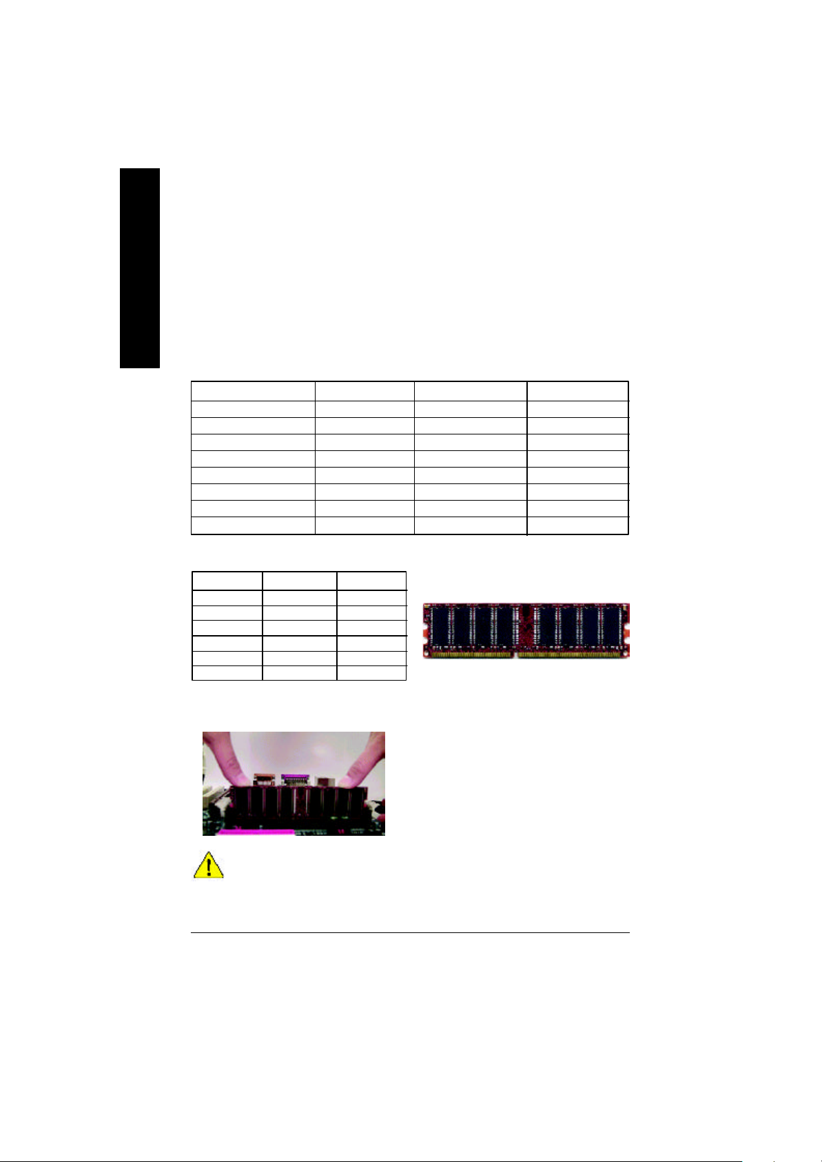
Step 2: Install memory modules
The motherboard has 3 dual inline memory module (DIM M) s ock ets, b ut it can only support a
maximum of 4 banks of DDR memory. DDR slot 1 uses 2 banks, DDR slot 2&3 share the remaining
English
2 banks. Please refer to the follow ing tables for pos sibl e m emor y c onfigura tions s upp orted. The
BIOS will automatically detects memory type and size. To install the memory module, just push it
vertically into the DIMM Slot .The DIM M mo dule can only fit in one direction due to the notch.
Memory size can vary between sockets.
Total Memory Sizes With Unbuffered DDR DIMM
Dev ices used on DIMM 1 DIMM x 64 / x 72 2 DIMMs x 64 / x 72 3 DIMMs x 64 / x 72
64 Mbit (2Mx 8x 4 banks) 128 MBytes 256 MBytes 256 MBytes
64 Mbit (1Mx 16x 4 banks) 32 MBy tes 64 MBy tes 96 MBy tes
128 Mbit(4Mx 8x 4 banks) 256 MBytes 512 MBytes 512 MBytes
128 Mbit(2Mx 16x 4 banks) 64 MBy tes 128 MBytes 196 MBytes
256 Mbit(8Mx 8x 4 banks) 512 MBytes 1 GBy tes 1 GBy tes
256 Mbit(4Mx 16x 4 banks) 128 MBytes 256 MBytes 384 MBytes
512 Mbit(16Mx 8x 4 banks) 1 GBy tes 2 GBy tes 2 GBy tes
512 Mbit(8Mx 16x 4 banks) 256 MBytes 512 MBytes 768 MBytes
Notes: Double-sided x 16 DDR memory dev ic es are not support by Intel 845 chipset.
D:Double Sided DIMM S:Single Sided DIMM
X:Not Use
DDR1 DDR2 DDR3
S S S
D S S
D D X
D X D
S D X
S X D
DDR
1. The DIMM slot has a notch, so the
DIMMmemory module can only fit in one direction.
2. Insert the DIMM memory module verticallyinto the
DIMM slot. Then push it down.
3. Close the plastic clip at both edges of theDIMM slots
to lock the DIMM module.
Reverse the installation steps when you wish to
remove the DIMM module.
? When STR/DIMM LED is ON, do not install/remove DIMM from socket.
? Please note that the DIMM module can only fit in one direction due to
the two notches. Wrong orientation will cause improper installation.
Please change the insert orientation.
- 10 -GA-8IRX Motherboard
Page 49

Step 3: Install expansion cards
1. Read the related ex pansion card’s instruction document before install the expansion card into
the computer.
2. Remove your computer’s chassis cover, screws and slot bracket from the computer.
3. Press the expansion card firmly into expansion slot in motherboard.
4. Be sure the metal contacts on the card are indeed seated in the slot.
5. Replace the screw to secure the slot bracket of the expansion card.
6. Replace your computer’s chassis cover.
7. Power on the computer, if necessary, setup BIOS utility of expansion card from BIOS.
8. Install related driver from the operating system.
Please carefully pull out the small whitedraw able bar at the end of th e AGP slot
when you try to install/ Uninstall the AGP
AGP Card
card. Please align the AGP card to the
onboard AGP slot and press firmly dow n on
the slot .M ake sure your AGP card is locked
by the small white- drawable bar.
English
Issues To Beware Of When Installing CNR
Please use standard CNR card like the one in order to avoid mechanical problem.
Standard CNR Card
- 11 - Hardware Installation Process
Page 50
Step 4: Connect ribbon cables, cabinet wires, and power
supply
English
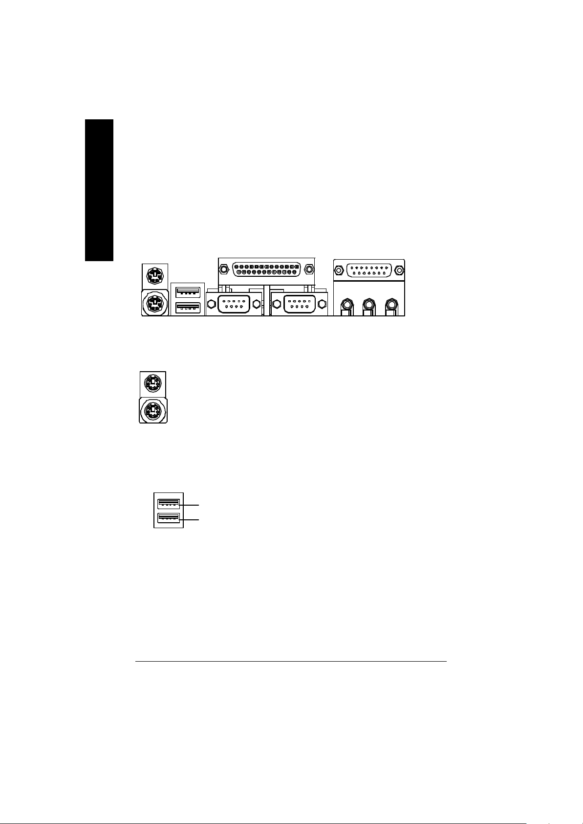
Step 4-1 : I/O Back Panel Introduction
?
?
?
? PS/2 Keyboard and PS/2 Mouse Connector
PS/2 Mouse Connector
(6 pin Female)
PS/2 Keyboard Connector
(6 pin Female)
? USB Connector
USB 0
USB 1
?This connector supports standard PS/2
keyboard and PS/2 mouse.
?Before you connect your device(s) into USB
connector(s), please make sure your device(s)
such as USB keyboard, mouse, scanner, zip,
speaker..etc. Hav e a standard USB interface.
Also make sure your OS (Win 95 with USB
supplement, Win98, Windows 2000, Windows
ME, WinNT with SP 6) supports USB controller.
If your OS does not support USB controller,
please contact OS vendor for possible patch or
driver upgrade. For more information please
contact your OS or device(s) vendors.
?
?
- 12 -GA-8IRX Motherboard
Page 51

? Parallel Port and Serial Ports (COMA/COMB)
?This connector supports 2 standard COM ports
Parallel Port
(25 pin Female)
COMA COMB
Serial Ports (9 pin Male)
and 1 Parallel port. Dev ice like printer can be
connected to Parallel port ; mouse and modem
etc can be connected to Serial ports.
English
? Game /MIDI Ports
Joystick/ MIDI (15 pin Female)
? Audio Connectors
MIC InLine Out
Line In
?This connector supports joystick, M IDI keyboard
and other relate audio devices.
? After install onboard audio driver, you may connect
speaker to Line Out jack, micro phone to MIC In jack.
Device like C D-ROM , w alkman etc can be connected
to Line-In jack.
Please note: Line Out 1: Line Out or SPDIF (The SPDIF
output is capable of providing digital audio to external
speakers or compressed AC3 data to an external Dolby
digital decoder). To enable SPDIF, simply insert SPDIF
connector into Line Out1. Line Out1 will become SPDIF
Out automatically.
To enable Four Speaker (for Creative 5880 audio only),
and Line In will become Line Out2 to support second
pair of stereo speakers.
If you want to realize the “Four Speaker & SPDIF
“ setup information in detail, please download
this manual from Gigabyte web
http://www.gigabyte.com.tw.
- 13 - Hardware Installation Process
Page 52
Step 4-2 :Connectors Introduction
English
A
R
Q
P
O
B
C
D
E
F
N
M
J
L
A) CPU_FAN J) IR/CIR
B) STR/DIMM_LED K) SCR
C) ATX L) WOL
D) FLOPPY M) CI
E) IDE1/IDE2 N) BAT
F) PWR_FAN O) AUX_IN
G) SYS_FAN P) CD_IN
H) F_PANEL Q) F_AUDIO
I) FRONT_USB R) AUX_12V
IK
G
H
- 14 -GA-8IRX Motherboard
Page 53

R) AUX_12V( +12V Power Connector)
123
GND
GND
+12V
+12V
4
? This connector (ATX +12V) is
used only for CPU Core Voltage.
English
A) CPU_FAN (CPU Fan Connector)
Sense
1
CPU_FAN
+12V/Control
GND
F) PWR_FAN (Power Fan Connector)
1
GND
+12V/Control
Sense
C) ATX (ATX Power Connector)
20
5V SB (Stand by +5V)
+12V
Power Good
GND
VCC
GND
VCC
GND
3.3V
3.3V
1
? Please note, a proper installation of the CPU
cooler is essential to prevent the CPU from
running under abnormal condition or
damaged by overheating.The CPU fan
connector supports Max. current up to 600mA .
G) SYS_FAN (System Fan Connector)
Sense
1
+12V/Control
GND
?AC power cord should only be connected to
your power supply unit after ATX power
cable and other related dev ices are firmly
connected to the mainboard.
VCC
VCC
-5V
GND
GND
GND
PS-ON(Soft On/Off)
GND
-12V
3.3V
- 15 - Hardware Installation Process
Page 54

E ) IDE1 / IDE2 Connector(Primary/Secondary]
English
? Important Notice:
Please connect first harddisk to IDE1
and connect CDROM to IDE2.
1
IDE2
1
IDE1
D) FLOPPY (Floppy Connector)
1
O ) AUX_IN ( AUX In Connector)
AUX-R
AUX-L
GND
AUX_IN
1
P) CD_IN (CD Audio Line In Connector)
CD-R
GND
1
CD-L
L) WOL(Wake on LAN)
1
+5V SB
GND
Signal
- 16 -GA-8IRX Motherboard
Page 55
I) FRONT_USB (Front USB Connector)
GND
NC
USB D3+
USB D3-
Power
1
NC
USB D2-
USB D2+
GND
Power
? Be careful with the polarity of the front
panel USB connector. Check the pin
assignment while you connect the front
panel USB cable. Please contact your
nearest dealer for optional front panel
USB cable.
English
Q) F_AUDIO (F_AUDIO Connector)
There are two types of front audio
connector, please refer to the tables
below before you install.
Incase speaker (L)
GND
Rear Audio (R)
GND
GND
Rear Audio (L)
1
GND
GND
Incase speaker (R)
GND
+12V
MIC
Front Audio (R)
Front Audio (L)
? If y ou want to use type 1-Front Audio
connector, y ou must remove 11-12, 13-14
Jumper.If y ou want to use type 2-Front Audio
connector, you must remove 3-4, 5-6 Jumper.
In order to utilize the front audio header, your
chassis must hav e front audio connector. Also
please make sure the pin assigment on the cable
is the same as the pin assigment on the MB
header. To find out if the chassis you are buy ing
support front audio connector, please contact your
dealer
GND
Rear Audio (L)
Rear Audio (R)
1
MIC
GND
Type2
Type1
Front Audio (R)
Front Audio (L)
- 17 - Hardware Installation Process
Page 56
B) STR/DIMM_LED
English
STR/DIMM LED
? Do not remove memory modules while
DIMM LED is on. It might cause short or
other unex pected damages due to the
2.5V stand by voltage. Remove memory
modules only when STR function is
disabled by jumper and AC Pow er cord is
disconnected.
K) SCR (Smart Card Reader Header)
NCNCDATA
NC
1
VCC
VCC
DATA
Clock
DATA
NC
DATA
GND
NC
NC
J) IR/CIR (IR/CIR )
NC
VCC
GND
IRRX
GND
NC
IRTX
CIRRX
1
NC
VCC
M) CI (CASE OPEN)
? This MB supports smart card reader. To
enable smart card reader function an optional
smart card reader box is required. Please
contact your autherized distributor.
? Make sure the pin 1 on the IR device is
aling w ith pin one the co nnec tor. To
enable the IR/CIR function on the board,
you are required to purchase an option IR/
CIR module. For detail information please
contact y our autherized Giga-Byte
distributor.
To use IR function only, please connect IR
module to Pin1 to Pin5.
? This 2 pin connector allows y our system to
enable or disable the system alarm if the sys
tem case begin remove.
GND
1
Signal
- 18 -GA-8IRX Motherboard
Page 57

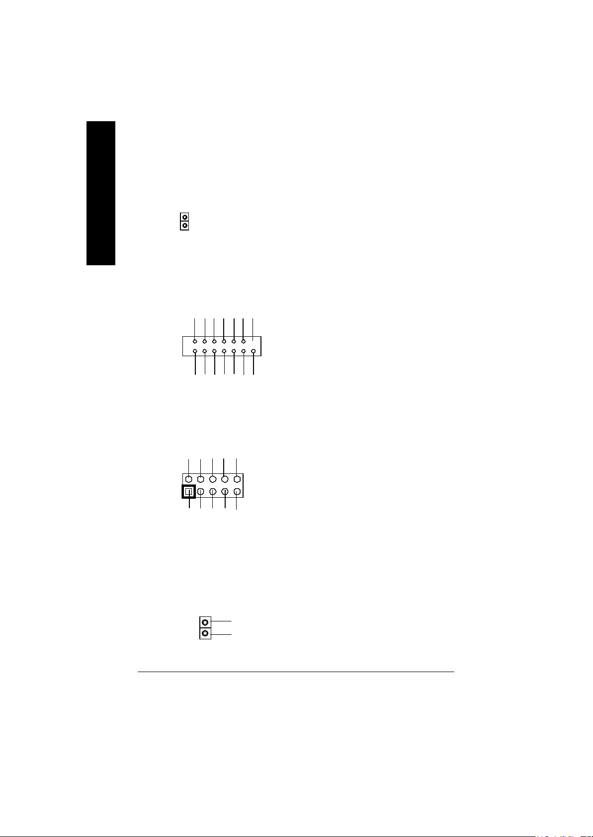
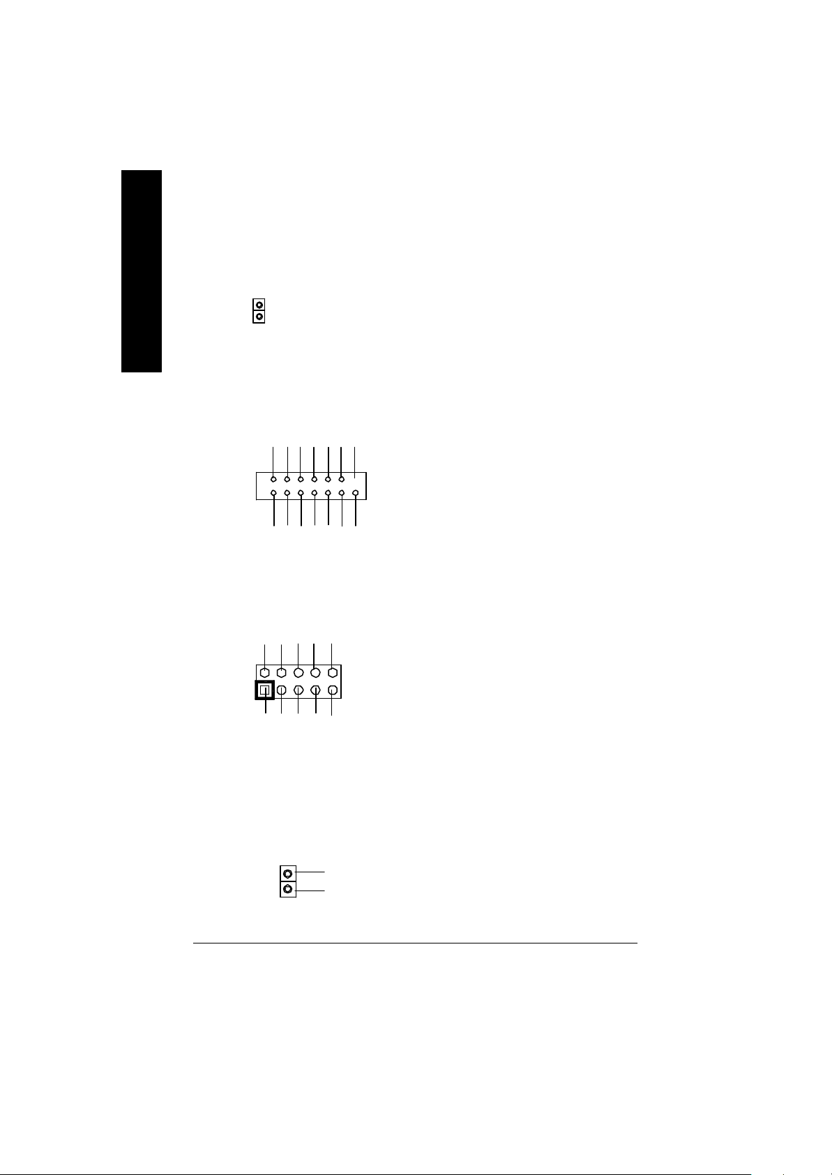
H) F_PANEL (2x7 pins jumper)
13
RST-
2 14
1
1
PW+
PW-
PD+
PD_GPD_Y-
HD+
Pin 2: LED cathode(-)
Pin 2- Pin 3: NC
Pin 4: Data(-)
Close: Reset H ardware Sy stem
Pin 2: LED cathode(-)
Pin 3: LED cathode(-)
Close: Power On/Off
RST+
SPK+
1
SPK-
HD-
HD (IDE Hard Disk Active LED) Pin 1: LED anode(+)
SPK (Speaker Connector) Pin 1: VCC(+)
RST (Reset Sw itch) Open: Normal Operation
PD+/PD_G-/PD_Y-(Power LED) Pin 1: LED anode(+)
PW (Soft Power Connector) Open: Normal Operation
English
? Please connect the power LED, PC speaker, reset switch and power switch etc of your chassis
front panel to the F_PANEL connector according to the pin assignment above.
N) BAT (Battery)
? Danger of explosion if battery is incorrectly
+
replaced.
? Replace only with the same or equivalent
type recommended by the manufacturer.
? Dispose of used batteries according to the
manufacturer’s instructions.
- 19 - Hardware Installation Process
CAUTION
Page 58

Chapter 3 BIOS Setup
BIOS Setup is an overview of the BIOS Setup Program. The program that allows users to modify
English
the basic system configuration. This type of information is stored in battery-backed CMOS RAM so
that it retains the Setup information when the pow er is turned o ff.
ENTERING SETUP
After power on the computer, pressing <Del> immediately during POST (Power On Self Test) it will allow y ou to
enter standard BIOS CMOS SETUP.
If y ou require more adv anced BIOS settings, please go to “ Adv anc ed BIOS” setting menu. To enter Adv anced
BIOS setting menu, press “Ctrl+F1” key on the BIOS screen.
GETTING HELP
The on-line description of the highlighted setup function is display ed at the bottom of the screen.
Press F1 to pop up a small help window that describes the appropriate key s to use and the possible selections
for the highlighted item. To ex it the Help Window press <Esc>.
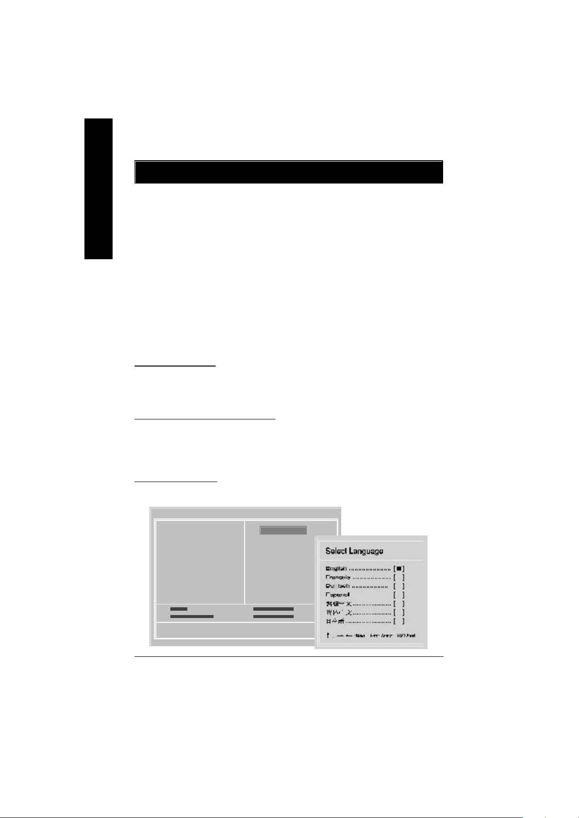
The Main Menu
Once y ou enter Award BIOS CMOS Setup Utility, the Main Menu will appear on the screen. The Main Menu
allows y ou to select from eight setup functions and two ex it choices. Use arrow key s to selec t among the items
and press <Enter> to accept or enter the sub-menu.
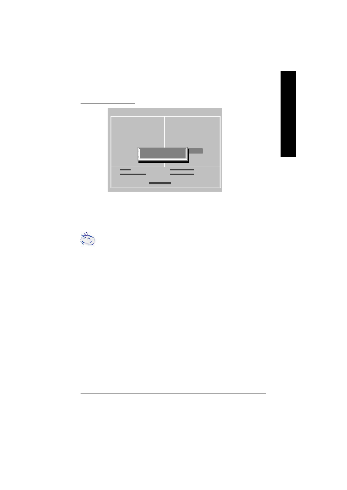
Dual BIOS / Q-Flash Utility
After power on the computer, pressing <Del> immediately during POST (Power On Self Test) it will allow y ou
to enter Award BIOS CMOS SETUP, then press <F8> to enter DualBIOS/Q-Flash utility. If you want to
detail information for “DualBIOS/Q-Flash Utility “, please download this manual from Gigabyte web
http://www.gigabyte.com.tw.
Select L anguage
Japanese, French, Spanish, Germany, Simplified Chinese, Traditional Chinese.
Main Menu
Status Page Setup Menu / Option Page Setup Menu
You can press <F3> to select multi language. There are 7 languages av ailable, including English,
CMOS Set up Utility-Cop yright (C) 198 4-2002 Award S oftware
?Standard CMOS Features Select Language
?Advanced BIOS Features Load Fail-Safe Defaults
?Integrated Peripherals Load Optimized Defaults
?Power Management Setup Set Supervisor Password
?PnP/PCI Configurations Set User Password
?PC Health Status Save & Exit Setup
?Frequency/Voltage Control Exit Without Saving
Top Performance
- 20 -GA-8IRX Motherboard
u
Page 59

? Standard CMOS Features
This setup page includes all the items in standard compatible BIOS.
? Advanced BIOS Features
This setup page includes all the items of Award special enhanced features.
? Advanced Chipset Features
This setup page includes all the items of chipset special features.
We would not suggest you change the chipset default setting unless you really
need it.
? Integrated Peripherals
This setup page includes all onboard peripherals.
We would not suggest you change the default setting unless you really need it.
For power End-User use only.
? Power Management Setup
This setup page includes all the items of Green function features.
We would not suggest you change the default setting unless you really need it.
For power End-User use only.
? PnP/PCI Configurations
This setup page includes all the configurations of PCI & PnP ISA resources.
We would not suggest you change the default setting unless you really need it.
For power End-User use only.
? PC Health Status
This setup page is the System auto detect Temperature, voltage, fan, speed.
? Frequency/Voltage Control
This setup page is control CPU’s clock and frequency ratio.
For power End-User use only.
? Select Language
This setup page is select multi language.
? Load Fail-Safe Defaults
Fail-Safe Defaults indicates the v alue of the system parameters which the sy stem w ould
be in safe configuration.
? Load Optimized Defaults
Optimized Defaults indicates the value of the system parameters which the system w ould
be in best performance configuration.
- 21 - BIOS Setup
English
Page 60

? Set Supervisor password
English
? Set User password
? Save & Exit Setup
? Exit Without Saving
Load Optimiz ed Default
Change, set, or disable password. It allows you to limit access to the sy stem and Setup,
or just to Setup.
Change, set, or disable password. It allows you to limit access to the system.
Save CMOS value settings to CMOS and exit setup.
Abandon all CMOS value changes and exit setup.
CMOS Set up Utility-Cop yright (C) 198 4-2002 Award S oftware
?Standard CMOS Features Select Language
?Advanced BIOS Features Load Fail-Safe Defaults
?Integrated Peripherals Load Optimized Defaults
?Power Management Setup Set Supervisor Password
?PnP/PCI Configurations Set User Password
?PC Health Status Save & Exit Setup
?Frequency/Voltage Control Exit Without Saving
Top Performance
Load O ptimized Defaults? (Y/N)?Y
? Load Optimized Defaults
Selecting this field loads the factory defaults for BIOS and Chipset Features which the
system automatically detects.
To Load Optimized, move cursor, by pressing the arrow keys on the keyboard ,to highlight
the optimized default and press enter key then press "Y" if you decide to load this option.
- 22 -GA-8IRX Motherboard
Page 61

Save & Exit Setup
CMOS Set up Utility-Cop yright (C) 198 4-2002 Award S oftware
?Standard CMOS Features Select Language
?Advanced BIOS Features Load Fail-Safe Defaults
?Integrated Peripherals Load Optimized Defaults
?Power Management Setup Set Supervisor Password
?PnP/PCI Configurations Set User Password
?PC Health Status Save & Exit Setup
?Frequency/Voltage Control Exit Without Saving
Top Performance
? To save exit the BIOS setting screen press F10, and press "Y" if
you want to save setting. By typing "N" or "ESC" will take you
back to setup screen.
If you want to realize the BIOS setup information in detail, please down-
load this manual from Gigabyte web http://www.gigabyte.com.tw.
SAVE to CMOS and EXIT (Y/N)?Y
English
- 23 - BIOS Setup
Page 62

Revision History
Chapter 4 Driver Intallation
Picture below are shown in Windows ME (IUCD driver version 1.9)
English
Insert the driver CD-title that came with your motherboard into your C D-ROM driv er, the d river
CD-title will auto start and show the installation guide. If not, please double click the CD-ROM
device icon in "M y computer", and execute the setup.exe.
A. Installing Intel 845 Chipset Driver
Please install this driver as the first priority .
this item installs the chipset driv er utility that
enableds Plug-n-Plag INF support for Intel
chipset component.
B. Installing Sound Driver
Click this item to install sound driv er.
A: Intel 845 Chipset Driver Installation
Follow the setup that showing on the scween to install the Utility.
A-1. Windows 9x/ME/2000/XP INF Update Utility
Click "Windows 9x/ME/2000/XP INF Update Utility"
item.
B: Sound Driver Installation
Revision History
1. 9
Press "Audio" icon.
A-2. Intel Ultra ATA Storage Driver
Click "Intel Ultra ATA Storage Driver"item.
1.Click "C reativ e C T5880 Sound Driv er"
item.
- 24 -GA-8IRX Motherboard
 Loading...