

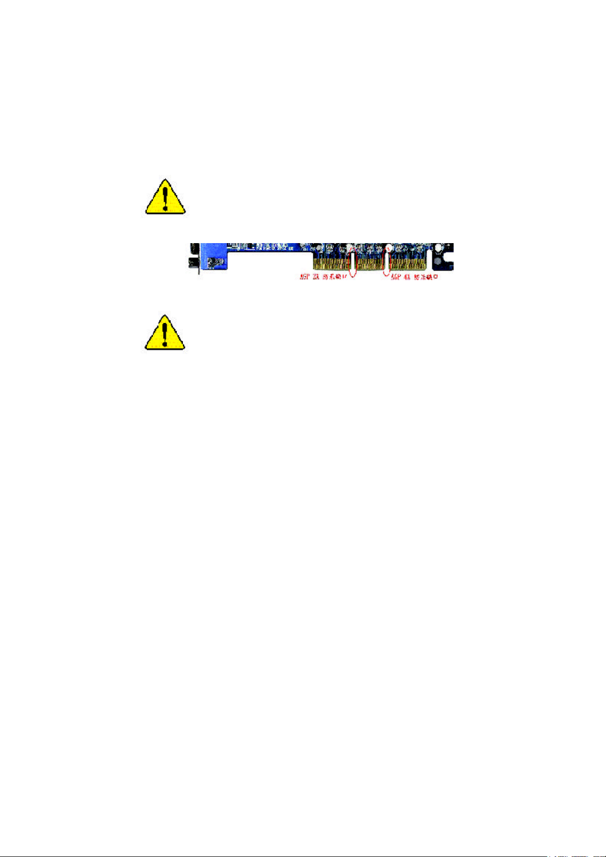
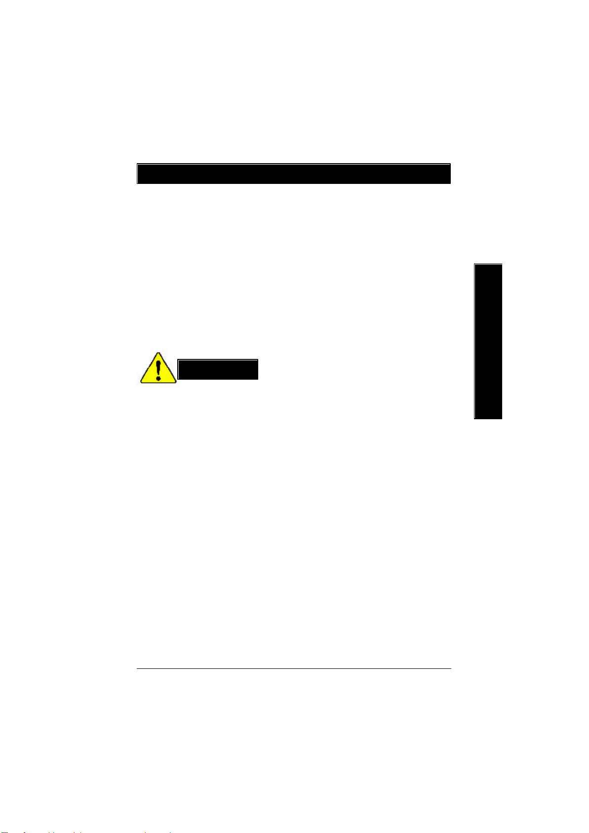
當您安裝 AG P 卡時,請注意下述注意事項。
您的顯示卡若有 AGP 4X 防呆缺口(如下圖),請
再次確認此卡的規格為 AGP 4X( 1.5V)。
不要使用 AGP 2X (3.3V)卡,因為 Intel
®
845(E/G)/850 (E)
晶片組不支援 AG P 2X(3.3V),若您使用 AGP 2X
(3.3V) 卡時, 此主機板上的零件將會被燒毀。
範例一:Diamond Vipper V770 這塊顯示卡的金手指部
份設計成2X/4X 插槽皆可使用,透過 Jumper可切換於
2X 或 4X ,出廠預設值為2X(3.3V),若您使用此卡在
GA-8IRE 主機板上,而且沒有將 Jum per 切換至4X (1.5V)
的模式時,開機後會燒毀主機板上的零件。
範例二:某些SiS 305 及 Power Color 所生產的某些ATi
Rage 128 Pro 等顯示卡的金手指部份設計成 2X/4X插槽
皆可使用,但只支援2X(3.3V),若您使用此卡在
GA-8IRE 主機板上,開機後會燒毀主機板上的零件。
注意:技嘉科技所生產的AG32S(G)顯示卡,雖然採用
AT i Rage 128 Pro 晶片,但此卡設計符合AGP4X 的規
格,因此不會發生如範例二中燒毀零件的情況,請
您安心使用。
M 本手冊所有提及之商標與名稱皆屬該公司所有。
M 在科技迅速的發展下,此發行手冊中的一些規格可能會有過時
不適用的敘述,敬請見諒。
M 在此不擔保本手冊無任何須疏忽或錯誤亦不排除會再更新發
行。手冊若有任何內容修改,恕不另行通知。
M 主機板上的任何貼紙請勿自行撕毀,否則會影響到產品保固期
限的認定標準。

Ausschlager Weg 41, 1F, 20537 Hamburg, Germany
( description of the apparatus, system, installation to which it refers)
(reference to the specification under which conformity is declared)
in accordance with 89/336 EEC-EMC Directive
EN 55011 Limits and methods of measurement
EN 55013
EN 55014 Limits and methods of measurement
EN 55015 Limits and methods of measurement
EN 55020
77
7 EN 55022 Limits and methods of measurement
77
DIN VDE 0855
part 10
part 12
77
7 CE marking
77
EN 60065
EN 60335
of radio disturbance characteristics of
industrial,scientific and medical (ISM
high frequency equipment
Limits and methods of measurement
of radio disturbance characteristics of
broadcast receivers and associated
equipment
of radio disturbance characteristics of
household electrical appliances,
portable tools and similar electrical
apparatus
of radio disturbance characteristics of
fluorescent lamps and luminaries
Immunity from radio interference of
broadcast receivers and associated
equipment
of radio disturbance characteristics of
information technology equipment
Cabled distribution systems; Equipment
for receiving and/or distribution from
sound and television signals
The manufacturer also declares the conformity of above mentioned product
with the actual required safety standards in accordance with LVD 73/23 EEC
Safety requirements for mains operated
electronic and related apparatus for
household and similar general use
Safety of household and similar
electrical appliances
(Stamp)
Declaration of Conformity
We, Manufacturer/Importer
(full address)
G.B.T. Technology Träding GMbH
declare that the product
Mother Board
GA-8IRE
is in conformity with
EN 61000-3-2*
77
7 EN 60555-2
77
EN 61000-3-3* Disturbances in supply systems cause
77
7 EN 60555-3
77
77
7 EN 50081-1
77
77
7 EN 50082-1
77
EN 55081-2
EN 55082-2
ENV 55104
EN50091-2
(EC conformity marking)
EN 60950
EN 50091-1
Manufacturer/Importer
Date : Apr. 30, 2002
Disturbances in supply systems cause
by household appliances and similar
electrical equipment “Harmonics”
by household appliances and similar
electrical equipment “Voltage fluctuations”
Generic emission standard Part 1:
Residual commercial and light industry
Generic immunity standard Part 1:
Residual commercial and light industry
Generic emission standard Part 2:
Industrial environment
Generic emission standard Part 2:
Industrial environment
lmmunity requirements for household
appliances tools and similar apparatus
EMC requirements for uninterruptible
power systems (UPS)
Signature:
Name:
Timmy Huang
Timmy Huang
DECLARATION OF CONFORMITY
Pe r FCC Part 2 Sect ion 2.1077(a)
Responsible Party
Name:
hereby declares that the product
Conforms to the following specifications:
FCC Part 15, Subpart B, Section 15.107(a) and Se ction 15.109
(a),Class B Digital Device
Supplementary Information:
This device complies with part 15 of the FCC Rules. Operation is
subject to the following two conditions: (1) This device may not
cause harmful and (2) this device must accept any inference received,
including that may cause undesired operation.
Representative Person’s Name:
Ad dress:
Phone/Fax No:
Pr oduct Name:
M odel Number :
Signature:
G .B.T. INC.
1735 8 Railroad Street
City of Industry, CA 91 748
(818) 854-9338/ (818) 854-9339
Motherboard
G A-8IRE
ERIC LU
Eric Lu
Dat e:
Apr. 30, 2002

Acronyms
Acronyms M eaning
ACPI Adv anced Configuration and Po wer Interface
APM Advanced Pow e r Management
AGP Accelerated Grap hics P ort
AMR Audio Modem R iser
ACR Adva nced Co mmunications Riser
BBS BIOS Boot Specification
BIOS Basic Input / Output System
CPU Central Proc essing Unit
CMOS Complementary M etal Oxide S emicondu ctor
CRIMM Continuity RIMM
CNR Comm unication and Networ king Riser
DMA Direct Memory Access
DMI Desktop M anagement Interface
DIMM Dual Inline M emory Module
DRM Dual Retention M echanism
DRAM Dynamic Random Access M emory
DDR Double Data Ra te
ECP Extended C apabilities Port
ESCD Extended Sy stem Configura tion Data
ECC Error C heck ing and C orrecting
EMC Electromagne tic C ompatibility
EPP Enhanced Paral lel Port
ESD Electrostatic Di scharge
FDD Floppy Disk Dev ice
FSB Front Side Bus
HDD Hard Disk Dev ice
IDE Integrated Dua l C hannel Enhanc ed
IRQ Interrupt Re quest
I/O Input / Output
IOAPIC Input Output Advanced P rogra mmable Input Co ntroller
ISAIndustry Standard Architecture
to be continued.. ....

Acronyms M eaning
LAN Local Area Network
LBA Logi cal Block Addressing
LED Li ght Emitting Diode
MHz M egahertz
MIDI Mus ical Interface Digital In terface
MTH Memory Translator H ub
MPT Memo ry Pro tocol Translator
NIC Netw ork Interface Card
OS Operating Sy s tem
OEM Original Equipme nt M anufacturer
PAC PCI A.G.P. Controller
POST Power -On Self Test
PCI Periphe ral C omponent In terconne ct
RIMM Rambus in-line M emory M odule
SCI Special C i rcumstance Instructions
SECC Single Edge Con tact C artridge
SRAM Static Random Access Memory
SMP Symmetric Mul ti-Processing
SMI System M anagement Interrupt
USB Univ ersal Serial Bus
VID Voltage ID
&
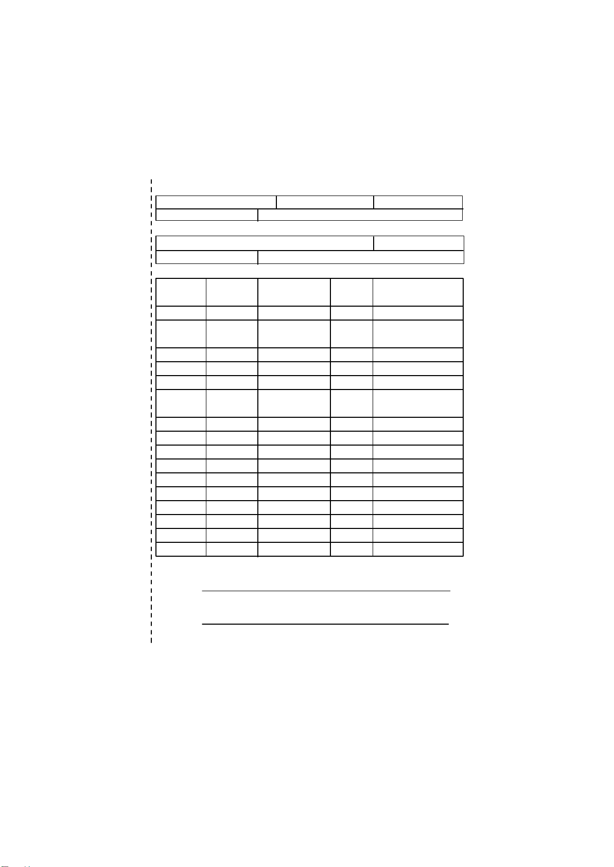
Technical Support/RMA Sheet
Customer/C ountry: Company: Phone No.:
Contact Person: E-mail Add. :
Model name/ Lot N umber: PCB revision:
BIOS version: O.S./A.S.:
Hardware Mfs. Model n ame Size: Driver/Utility:
Configu ration
CPU
Memory
Brand
Video Card
Audio Card
HDD
CD-ROM /
DVD-ROM
Modem
Network
AMR / CNR
Keyboard
Mouse
Power supply
Other Device
Problem Desc ription:
&

GA-8IRE
P4 泰坦DDR 主機板
中文安裝使用手冊
®
Pentium
4 處理器主機板
Rev. 2001
12MC-8I RE-2001

目錄
清點附件 .......................................................................................3
警告標語 .......................................................................................3
第一章 序言 ..................................................................................4
特色彙總 ............................................................................................................. 4
GA-8IRE 主機板Layout 圖 .............................................................................. 6
中文
第二章 硬體安裝步驟 ..................................................................7
步驟 1:安裝中央處理器(CP U) ...........................................................................8
步驟1-1:中央處理器之安裝 .................................................................. 8
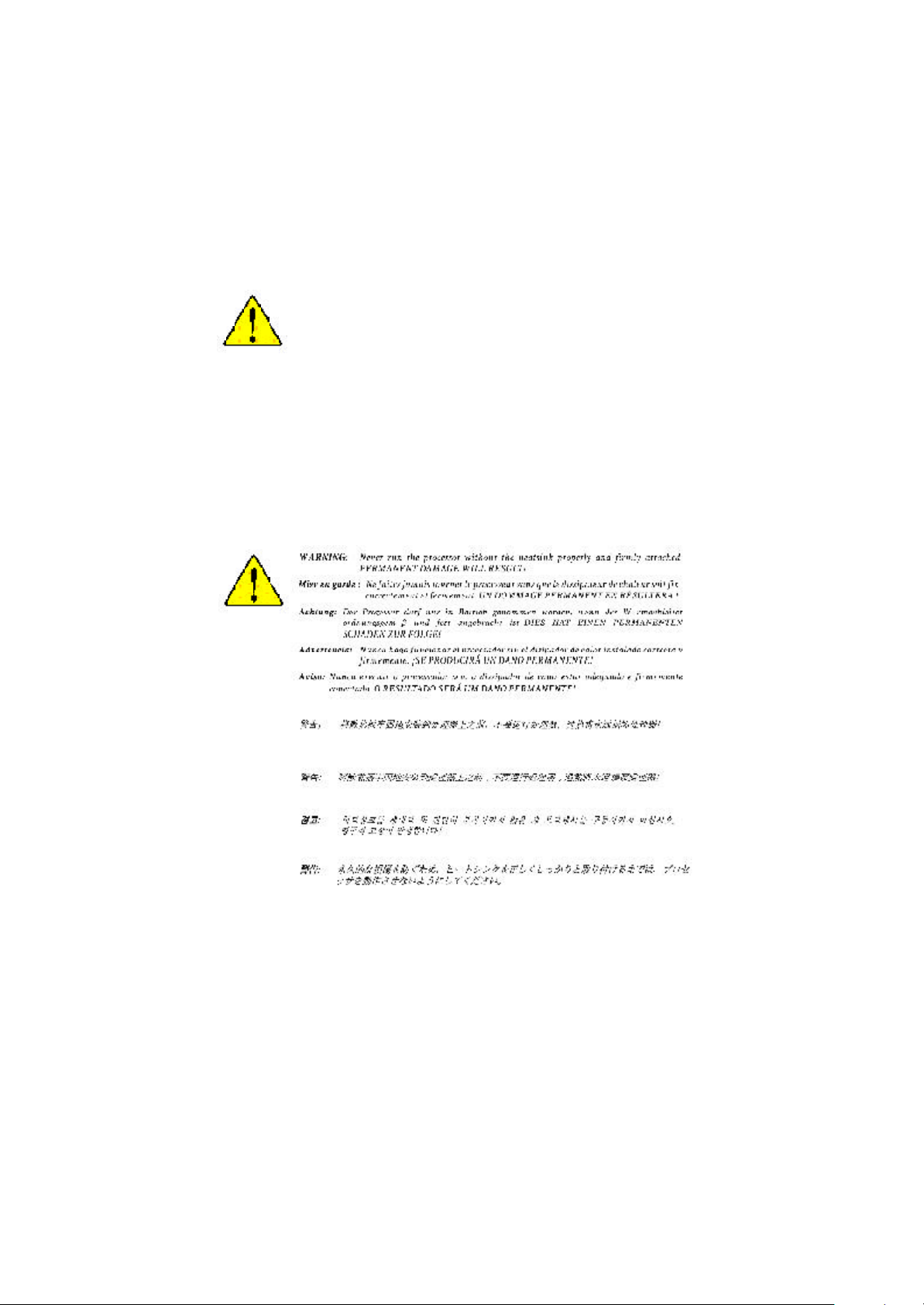
步驟1-2:中央處理器之散熱裝置安裝 .................................................. 9
步驟 2:安裝記憶體模組 ...................................................................................10
步驟 3:安裝介面卡 ............................................................................................. 11
步驟 4:連接所有訊號線、排線、電源供應線及面板控制線 .............12
步驟4-1 :後方I/O 裝置鐵片介紹 .......................................................... 12
步驟4-2:插座及跳線介紹 .................................................................... 14
第三章BIOS 組態設定................................................................ 19
主畫面功能...................................................................................................... 19
載入Optimized 預設值 ................................................................................. 21
離開SETUP 並儲存設定結果................................................................. 21
Q-Flash 功能介紹 ...........................................................................................22
第四章 安裝驅動程式 ................................................................ 24
第五章BIOS 更新程序 ................................................................25
- 2 -GA-8IRE 主機板
清點附件
þ The GA-8IRE 主機板一片
þ 硬碟插座排線 x 1 / 軟碟插座排線 x 1
þ 主機板驅動程式光碟片
þ GA-8IRE 中文安裝手冊
þ 電腦組裝秘笈
警告標語
主機板由許多精密的積體電路及其他元件所構成,這些積體電路很容易因為遭到靜
電影響而損失。所以請在正式安裝前,做好下列準備。
1. 請將電腦的電源關閉,最好拔除電源插頭。
2. 拿取主機板時請儘量避免觸碰金屬接線部份。
3. 拿取積體電路元件(CPU 、RAM )時,最好能夠戴上有防靜電手環。
4. 在積體電路未安裝前,需將元件置放在靜電墊或防靜電袋內。
5. 當您將主機板中的ATX電源供應器插座上的插頭拔除時,請確認電源供應
器的開關是關閉狀況。
中文
安裝主機板至機殼中…
大多數電腦機殼的底部會有多個固定孔孔位,可使主機板確實固定並且不會短
路。請小心不要讓螺絲接觸到任何PC B 板上的線路或零件,當印刷電路主機板表
面線路接近固定孔時,您可使用塑膠墊片來讓螺絲與主機板表面隔離過,避免造成
主機板損壞或故障。
- 3 -
序言

第一章 序言
特色彙總
規格 l 主機板採四層設計ATX規格 30.5 公分x 22.8 公分
中央處理器 l Socket478 支援最新Intel M icro FC -PGA2 Pentium®4處理器
晶片組 l Chipset 82845 HOS T/AGP/Controller
記憶體 l 3 184-pin DDR DIM M 插槽
中文
I/O 控制器 l IT8702
擴充槽 l 1 AGP 擴充槽支援 4X (1.5 V)裝置
內建IDE l 2 IDE bus master (UDM A 33/ATA 66/ATA 100) IDE埠可連接
內建周邊設備 l 1 個軟碟插座支援兩台磁碟機(360K,720K,1.2M ,1.44M
內建音效晶片 l Sigmatel 9721T CODEC
PS/2 插座 l PS/2 鍵盤插座及PS/2 滑鼠插座
BIOS l 使用經授權AWARD BIOS, 2M x 2 bit快閃記憶體
l 支援Intel
l Intel Pentium
l 2nd 快取記憶體取決於C PU
l 82801BA(ICH 2)I/O Controller Hub
l 支援PC 1600 DDR 或 PC2100 DDR DIMM
l 最大支援到 2GB
l 支援2.5V DD R DIM M
l 支援 64bit ECC type DRAM integrity 模式
l 5 PCI 擴充槽支援33MHz 及PCI2.2 c ompli ant
4 ATAPI裝置
l 支援PIO mode 3,4,5,U DM A33/ATA66/ATA100 IDE及ATAPI
CD-ROM
及2.88M bytes)
l 1 組並列埠插座可支援N ormal/EPP/ECP 模式
l 2 組串列埠插座(COM A & COM B)
l 4 組U SB埠插座(後端通用串列埠 x 2,前端通用串列埠 x 2)
l Line In/Line Out/M ic In/CD In/AUX_IN/Game Port
®
®
Pentium
4 (Northwood, 0.13 m) 處理器
®
4 400MH z FSB
續下頁.......
- 4 -GA-8IRE 主機板
附加特色 l PS/2 滑鼠開機
l 外接型數據機開機功能
l 支援STR 功能(Suspend-To-RAM)
l AC Recovery
l USB 鍵盤/滑鼠w ake up from S3
l 支援@BIOS
l 支援Easy Tune III
無跳線帽超頻功能 l Over 時脈 (CPU /DDR/AGP) by BIOS
請依據您C P U 的規格來設定CPU 的頻率,我們不建議您將系統速度設定超
過硬體之標準範圍, 因為這些規格對於周邊設備而言並不算是符合標準規
格。如果您要將系統速度設定超出標準規格 , 請評估您的硬體規格設定, 例
如;CPU ,顯示卡, 記憶體,硬碟來設定.
中文
- 5 -
序言
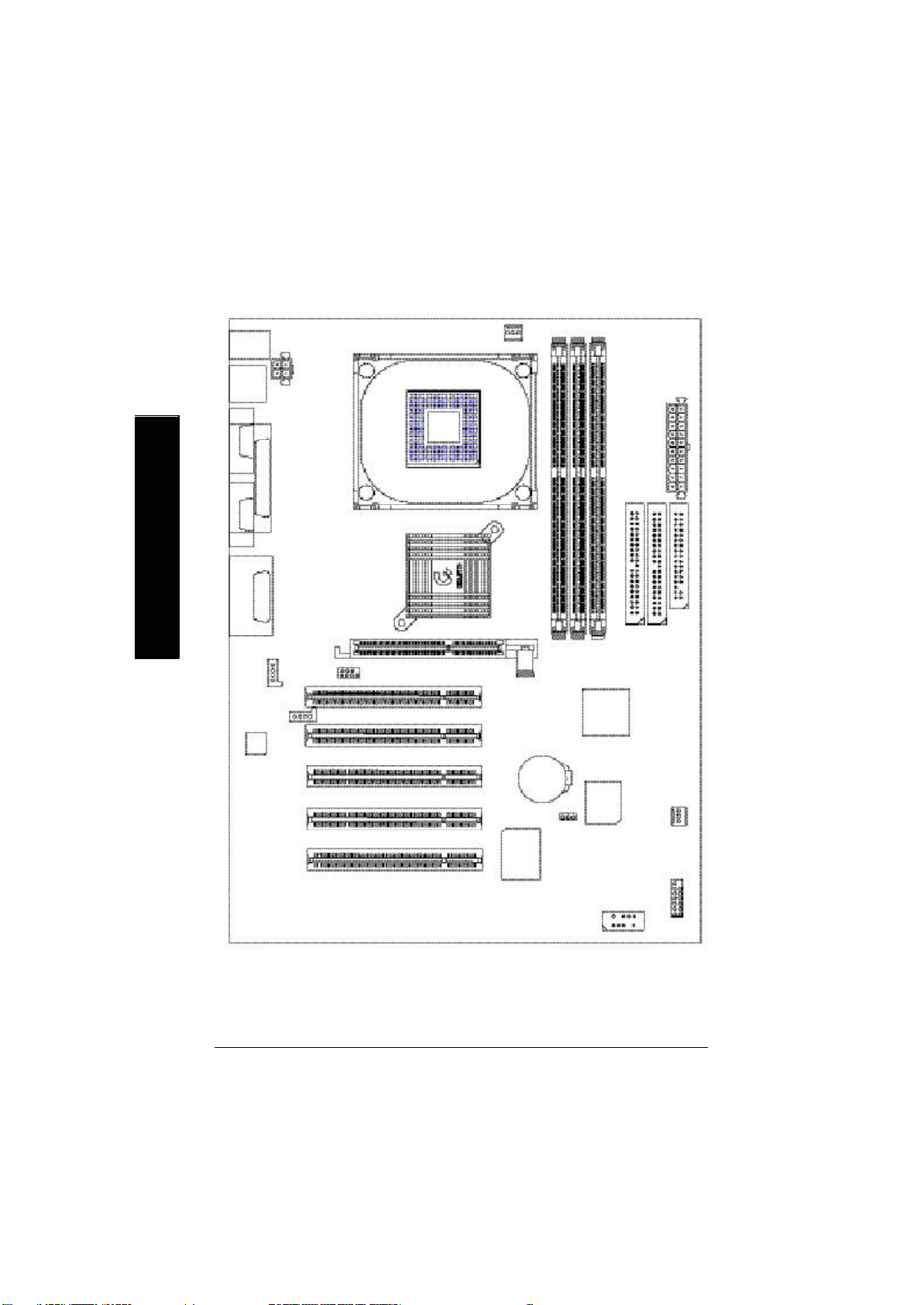
GA-8IRE 主機板 Layout 圖
中文
KB_MS
USB
COMA
COMB
LINE_OUTMIC_IN
LINE_IN
AC97
LPT1
GAME
CD_IN
AUX_12V
AUX_IN
P4 Titan-DDR
F_AUDIO
SOCKET478
GA-8IRE
CPU_FAN
PCI1
PCI2
PCI3
PCI4
PCI5
AGP
IT8702
BATTERY
DDR1
CLR_CMOS
DDR2
ICH2
BIOS
DDR3
IDE2
ATX
IDE1
SYS
FAN
F_PANEL
FLOPPY
FRONT USB
- 6 -GA-8IRE 主機板
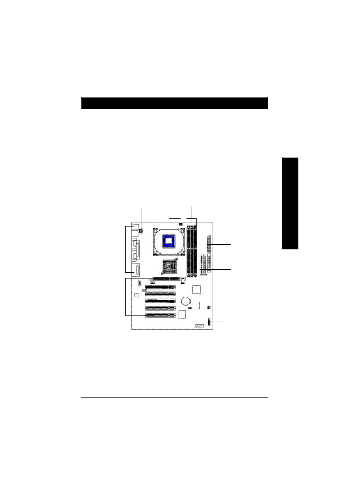
第二章 硬體安裝步驟
請依據下列方式,完成電腦的安裝:
步驟 1 - 安裝中央處理器 (C PU )
步驟 2 - 安裝記憶體模組
步驟 3 - 安裝所有介面卡
步驟 4 - 連接所有訊號線、排線、電源供應線及面板控制線
步驟 5 - 完成 BIOS 組態設定
步驟 6 - 安裝軟體驅動程式
中文
步驟 4
步驟 3
步驟 4
步驟 2步驟 1
步驟 4
步驟 4
- 7 - 硬體安裝步驟
 Loading...