


FCC Compliance Statement:
This equipment has been tested and found to comply with limits for a Class B digital device, pursuant to Part 15 of the FCC rules. These limits are designed to provide reasonable protection against harmful interference in residential installations. This equipment generates, uses, and can radiate radio frequency energy, and if not installed and used in accordance with the instructions, may cause harmful interference to radio communications.
However, there is no guarantee that interference will not occur in a particular installation. If this equipment does cause interference to radio or television equipment reception, which can be
determined by turning the equipment off and on, the user is encouraged to try to correct the interference by one or more of the following measures:
-Reorient or relocate the receiving antenna
-Move the equipment away from the receiver
-Plug the equipment into an outlet on a circuit different from that to which the receiver is connected
-Consult the dealer or an experienced radio/television technician for additional suggestions
You are cautioned that any change or modifications to the equipment not expressly approve by the party responsible for compliance could void Your authority to operate such equipment.
This device complies with Part 15 of the FCC Rules. Operation is subjected to the following two conditions 1) this device may not cause harmful interference and 2) this device must accept any interference received, including interference that may cause undesired operation.

Declaration of Conformity
We, Manufacturer/Importer
(full address)
G.B.T. Technology Träding GMbH
Ausschlager Weg 41, 1F, 20537 Hamburg, Germany
declare that the product
( description of the apparatus, system, installation to which it refers)
Mother Board
GA-6VM7-4E
is in conformity with
(reference to the specification under which conformity is declared) in accordance with 89/336 EEC-EMC Directive
EN 55011 |
Limits and methods of measurement |
|
of radio disturbance characteristics of |
|
industrial, scientific and medical (ISM |
|
high frequency equipment |
EN55013 |
Limits and methods of measurement |
|
of radio disturbance characteristics of |
|
broadcast receivers and associated |
|
equipment |
EN 55014 |
Limits and methods of measurement |
|
of radio disturbance characteristics of |
|
household electrical appliances, |
|
portable tools and similar electrical |
|
apparatus |
EN 55015 |
Limits and methods of measurement |
|
of radio disturbance characteristics of |
|
fluorescent lamps and luminaries |
EN 55020 |
Immunity from radio interference of |
|
broadcast receivers and associated |
|
equipment |
EN 55022 |
Limits and methods of measurement |
|
of radio disturbance characteristics of |
|
information technology equipment |
DIN VDE 0855 |
Cabled distribution systems; Equipment |
part 10 |
for receiving and/or distribution from |
part 12 |
sound and television signals |
CE marking
EN 61000-3-2* |
Disturbances in supply systems caused |
EN60555-2 |
by household appliances and similar |
|
electrical equipment “Harmonics” |
EN61000-3-3* |
Disturbances in supply systems caused |
EN60555-3 |
by household appliances and similar |
|
electrical equipment “Voltage fluctuations” |
EN 50081-1 |
Generic emission standard Part 1: |
|
Residual, commercial and light industry |
EN 50082-1 |
Generic immunity standard Part 1: |
|
Residual, commercial and light industry |
EN 55081-2 |
Generic emission standard Part 2: |
|
Industrial environment |
EN 55082-2 |
Generic immunity standard Part 2: |
|
Industrial environment |
ENV 55104 |
Immunity requirements for household |
|
appliances tools and similar apparatus |
EN 50091- 2 |
EMC requirements for uninterruptible |
|
power systems (UPS) |
 (EC conformity marking)
The manufacturer also declares the conformity of above mentioned product with the actual required safety standards in accordance with LVD 73/23 EEC
EN 60065 |
Safety requirements for mains operated |
|
electronic and related apparatus for |
|
household and similar general use |
EN 60335 |
Safety of household and similar |
|
electrical appliances |
(Stamp)
EN 60950 |
Safety for information technology equipment |
|
including electrical business equipment |
EN 50091-1 |
General and Safety requirements for |
|
uninterruptible power systems (UPS) |
Manufacturer/Importer |
|
|
|
|
Signature |
: |
Rex Lin |
Date: Feb. 9, 2001 |
Name |
: |
Rex Lin |
6VM7-4E
Socket 370
Socket 370 REV. 5.0 Second Edition R-50-02-010627C 12MC-6VM74E-5002

:
1) |
|
|
|
|
|
2) |
|
|
|
|
|
3) |
|
|
|
|
|
4) |
|
|
|
|
|
5) |
|
|
|
|
|
|
|
|
6) |
Suspend to RAM |
STR |
|
|
|
7) Four Speaker & SPDIF |
Four Speaker & SPDIF |
|
|
|
|
8) |
@ BIOSTM & EasyTuneIIITM |
@BIOS TM Easy TuneIIITM |
|
|
|
9) BIOS |
BIOS |
|
|
|
|
10) |
|
|
|
|
|

|
P.1 |
|
|
|
P.2 |
|
|
|
P.3 |
|
|
6VM7-4E |
P.5 |
|
|
CPU / |
P.6 |
|
|
|
P.28 |
|
|
|
P.29 |
|
|
Suspend to RAM |
P.30 |
|
|
Four Speaker & SPDIF ( ) |
P.36 |
|
|
@BIOSTM |
P.42 |
|
|
EasyTuneIIITM |
P.43 |
|
|
|
P.44 |
|
|
BIOS |
P.45 |
|
|
|
P.73 |
|
|

6VM7-4E
|
|
|
|
|
|
|
|
5.0 |
6VM7-4E |
|
Jan. 2001 |
5.0 |
6VM7-4E |
|
Jun.2001 |
2001 6 27
1

þ6VM7-4E
þ(TUCD)
þ6VM7-4E
2

6VM7-4E
|
Ÿ |
Micro ATX 24.4 x 21.0 |
|
CPU |
Ÿ |
Socket 370 |
|
|
|
Intel Pentiumâ!!! 100/133MHz FSB, FC-PGA |
|
|
|
Intel CeleronTM 66MHz FSB, FC-PGA |
|
|
|
VIA Cyrix â III 100/133MHz FSB, PPGA |
|
|
Ÿ |
L2 CPU |
|
|
Ÿ |
VT82C694X (VIA Apollo Pro 133A) |
|
|
Ÿ |
VT82C686B |
|
|
Ÿ |
ICS 9248DF-39 |
|
|
Ÿ 66/100/133 MHz system bus speeds (PCI 33MHz) |
||
|
Ÿ 75/83/112/124/140/150 MHz system bus speeds |
||
|
|
(PCI 44MHz) ( ) |
|
|
Ÿ |
2 168-pin DIMM |
|
|
Ÿ |
PC-100 / PC-133 SDRAM VCM SDRAM |
|
|
Ÿ |
1.5GB |
|
|
Ÿ |
3.3V SDRAM DIMM |
|
|
Ÿ |
72 ECC DIMM |
|
I/O |
Ÿ |
VT82C686B |
|
|
Ÿ |
1 |
AGP , 4X mode AGP 2.0 compliant |
|
Ÿ |
3 |
32-bit PCI Bus |
|
Ÿ |
1 |
AMR (Audio Modem Riser) |
IDE |
Ÿ |
IDE VIA VT82C82686B PCI , |
|
|
|
PIO, Bus Master (Ultra DMA33 ATA 66/100) |
|
|
|
IDE HDD/CD-ROM |
|
|
Ÿ |
IDE |
|
|
Ÿ |
1 |
|
|
|
(360K ,720K ,1.2M ,1.44M 2.88M bytes) |
|
|
Ÿ |
1 |
Normal/EPP/ECP |
|
Ÿ |
2 |
(COM A COM B) |
|
Ÿ |
4 |
USB |
|
Ÿ |
CPU/ |
|
|
Ÿ |
CPU/ |
|
|
Ÿ |
|
|
|
Ÿ |
CPU |
|
…
3
PS/2 |
Ÿ |
PS/2â PS/2â |
BIOS |
Ÿ |
AMI BIOS, 2M bit |
|
Ÿ |
VIA (VIA VT82C686B) |
|
|
( ) |
|
Ÿ |
Creative CT5880 |
|
Ÿ Line In / Line Out / Mic In / AUX In / CD In / TEL / |
|
|
|
Game Port / Four Speaker |
|
Ÿ |
(WOL) |
|
Ÿ |
/ |
|
Ÿ |
3 |
|
Ÿ |
|
|
Ÿ |
USB / |
|
Ÿ |
STR |
|
Ÿ Support @BIOS™ and EasyTuneIII™ |
|
4

6VM7-4E
6VM7-4E
PS/2
|
|
|
|
|
|
|
|
|
|
USB1 |
|
|
JP3 |
JP16 |
|
|
|
|
|
|
|||
|
|
|
|
|
|
|
|
|
|
|
|
|
|
||
|
|
|
|
|
|
|
|
|
|
COMA |
LPT |
|
|||
|
|
|
|||||
|
|
|
|||||
|
|
|
|
||||
|
|
|
|
||||
COMB |
SW2 |
|
|
AUDIO |
|
|
|
|
|
|
|
|
|
|
J7 |
|
|
|
|
|
|
|
|
|
|
|
||
|
|
|
|
|
|
|
|
|
|
|
||
|
GAME & |
J8 |
|
|
|
|
|
|
|
|
|
J5 |
|
|
|
|
|
|
|
|
|
|
|||
|
||||||||||||
|
|
|
|
|
|
|
|
|
|
|
|
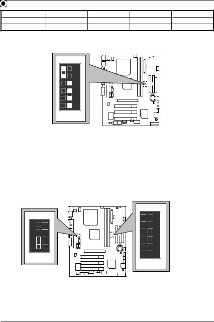
PGA 370
CPU
VT82C694X
6VM7-4E
JP7
DIMM1
AGP 1
AC97
PCI1
PCI2
CT5880 ES1373 PCI3 /
|
|
JP5 |
|
JP8 |
AMR |
JP6 |
JP4 |
|
USB2 |
||
|
|
|
JP9 |
LED1/ |
|
|
LED2 |
|
ATX POWER |
JP15 |
|
IDE1 |
IDE2 |
FLOPPY |
SW1 |
|
|
DIMM2 |
|
|
|
JP1 |
|
|
BAT1 |
|
|
|
J1 |
JP23 |
|
|
|
J3 |
|
|
JP2 |
|
VT82C |
|
|
686B |
BIOS |
|
|
|
|
|
BZ1 |
|
J2 |
|
|
5

6VM7-4E
$CPU / |
|
CPU |
P.7 |
|
P.15 |
|
P.15 |
COM A / COM B / LPT |
P.15 |
USB1 |
P.16 |
PS/2 PS/2 |
P.16 |
USB 2 |
P.17 |
JP16 (CPU ) |
P.17 |
JP15 ( ) |
P.18 |
JP2 ( ) |
P.18 |
ATX |
P.19 |
Floppy Port ( ) |
P.19 |
IDE 1 / IDE 2 |
P.20 |
J7 (TEL) ( ) |
P.20 |
J5 (AUX IN ) |
P.21 |
J8 (CD Audio Line in ) |
P.21 |
J3 (Ring Power On) ( ) |
P.22 |
J1 (Wake on LAN) ( ) |
P.22 |
JP9 (STR & LED 1: DIMM ) |
P.23 |
|
P.24 |
J2 (2x11 Pins ) |
P.24 |
JP1 ( CMOS ) |
P.25 |
JP23 ( ) |
P.25 |
JP4/JP5/JP6 ( AC97& AMR ) [ ] |
P.26 |
JP3 (USB ) |
P.26 |
JP7 (STR ) |
P.27 |
JP8 ( ) |
P.27 |
6

6VM7-4E
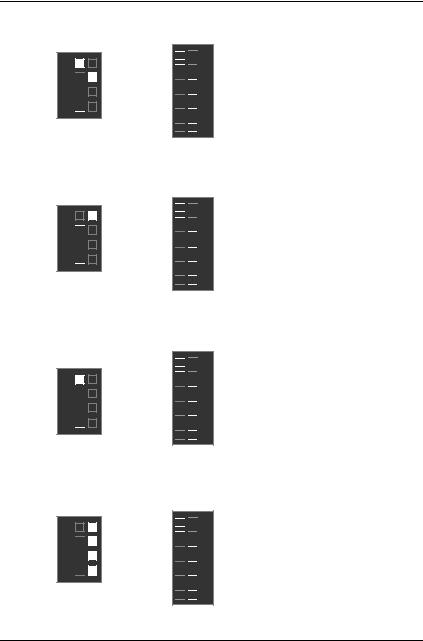
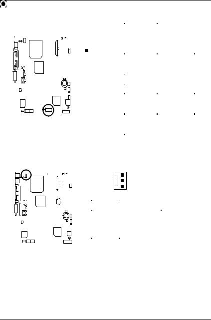
CPU
66, 100, 133MHz Auto (SW1)DIP SWITCH (SW2) CPU CPU 500MHz – 1GHz.
|
SW1: |
|
|
|
|
|
|
|
|
|
|
|
O: ON, X: OFF |
|
|
|||
|
CPU |
|
PCICLK |
|
1 |
|
2 |
|
|
3 |
|
4 |
5 |
|
6 |
|
||
|
Auto |
|
33.3 |
|
|
X |
|
X |
|
|
X |
|
X |
|
O |
|
O |
|
|
66 |
|
33.3 |
|
|
O |
|
O |
|
|
X |
|
X |
|
X |
|
X |
|
|
75 |
|
37.5 |
|
|
O |
|
O |
|
|
O |
|
X |
|
X |
|
X |
|
|
83 |
|
41.6 |
|
|
O |
|
O |
|
|
X |
|
O |
|
X |
|
X |
|
|
100 |
|
33.3 |
|
|
O |
|
X |
|
|
X |
|
X |
|
X |
|
X |
|
|
112 |
|
37.3 |
|
|
O |
|
X |
|
|
O |
|
X |
|
X |
|
X |
|
|
124 |
|
31 |
|
|
X |
|
X |
|
|
X |
|
O |
|
X |
|
X |
|
|
133 |
|
33.3 |
|
|
X |
|
X |
|
|
X |
|
X |
|
X |
|
X |
|
|
140 |
|
35 |
|
|
X |
|
X |
|
|
O |
|
O |
|
X |
|
X |
|
|
150 |
|
37.5 |
|
|
X |
|
X |
|
|
O |
|
X |
|
X |
|
X |
|
|
|
|
|
|
|
|
|
|
|
|
|
|
|
|
|
|
|
|
|
M DIP SWITCH (SW2) CPU |
|
||||||||||||||||
|
|
|
|
|
|
|
|
|
|
|
|
|
||||||
|
SW2: |
|
|
|
|
|
|
|
|
|
|
|
|
|
|
|
|
|
|
|
|
|
|
|
|
|
|
|
|
|
|
|
|
|
|||
|
FREQ. RATIO |
|
|
|
|
|
|
|
DIP SWITCH |
|
|
|
|
|
||||
|
|
|
|
|
1 |
|
|
2 |
|
3 |
|
4 |
|
|
||||
|
X3 |
|
|
|
O |
|
|
X |
|
O |
|
|
O |
|
|
|||
|
X3.5 |
|
|
|
X |
|
|
X |
|
O |
|
|
O |
|
|
|||
|
X4 |
|
|
|
O |
|
O |
|
X |
|
|
O |
|
|
||||
|
X4.5 |
|
|
|
X |
|
O |
|
X |
|
|
O |
|
|
||||
|
X5 |
|
|
|
O |
|
|
X |
|
X |
|
|
O |
|
|
|||
|
X5.5 |
|
|
|
X |
|
|
X |
|
X |
|
|
O |
|
|
|||
|
X6 |
|
|
|
O |
|
O |
|
O |
|
|
X |
|
|
||||
|
X6.5 |
|
|
|
X |
|
O |
|
O |
|
|
X |
|
|
||||
|
X7 |
|
|
|
O |
|
|
X |
|
O |
|
|
X |
|
|
|||
|
X7.5 |
|
|
|
X |
|
|
X |
|
O |
|
|
X |
|
|
|||
|
X8 |
|
|
|
O |
|
O |
|
X |
|
|
X |
|
|
||||
|
X8.5 |
|
|
|
O |
|
|
X |
|
O |
|
|
O |
|
|
|||
|
X9 |
|
|
|
X |
|
|
X |
|
O |
|
|
O |
|
|
|||
|
X9.5 |
|
|
|
X |
|
O |
|
O |
|
|
O |
|
|
||||
|
X10 |
|
|
|
X |
|
O |
|
X |
|
|
X |
|
|
||||
|
X10.5 |
|
|
|
O |
|
O |
|
X |
|
|
O |
|
|
||||
|
X11 |
|
|
|
O |
|
|
X |
|
X |
|
|
X |
|
|
|||
|
X11.5 |
|
|
|
X |
|
O |
|
X |
|
|
O |
|
|
||||
|
X12 |
|
|
|
O |
|
|
X |
|
X |
|
|
O |
|
|
|||
|
X13 |
|
|
|
X |
|
|
X |
|
X |
|
|
O |
|
|
|||
|
|
|
|
|
|
|
|
|
|
|
|
|
|
|
|
|
|
|
7
X14 |
O |
O |
O |
X |
X15 |
X |
O |
O |
X |
X16 |
O |
X |
O |
X |
F Auto : |
|
|
|
|
|
ON |
|
|
|
|
6 |
|
|
|
|
5 |
|
|
|
|
4 |
|
|
|
|
3 |
|
|
|
|
2 |
|
|
|
|
1 |
|
|
|
|
SW1 |
|
|
|
« :
1.66, 100, 133MHz CPU, ”Auto”
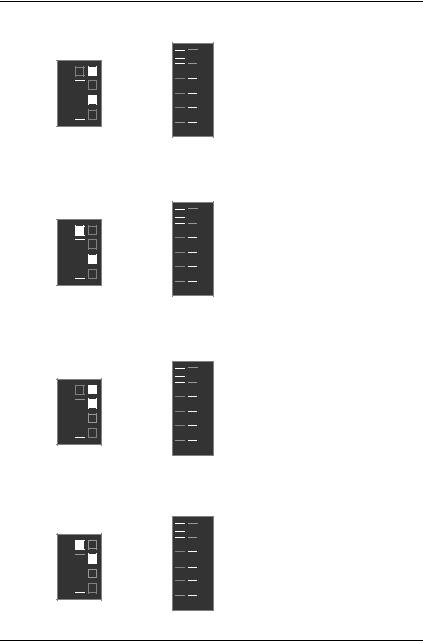
2.75/83/112 / 124 / 142 /150MHz,. 75/83/112 / 124 / 142 /150MHz ,, ;CPU, , ,
1.CeleronTM 533 / 66MHz FSB
ON


 1
1 
 2
2 
 3
3 

 4
4
SW2
SW2
ON

 1
1 
 2
2 
 3
3 
 4
4 

 5
5 

 6
6
SW1
8
6VM7-4E
2. Celeron TM 566 / 66 MHz FSB
ON
 4 3 2 1
SW2
ON


 1
1 
 2
2 
 3
3 
 4
4 

 5
5 


 6
6
SW1
3. Celeron TM 600 / 66 MHz FSB
ON
 4 3 2 1
SW2
ON


 1
1 
 2
2 
 3
3 
 4
4 

 5
5 


 6
6
SW1
4. Celeron TM 633 / 66 MHz FSB
ON
 4 3 2 1
SW2
ON


 1
1 
 2
2 
 3
3 
 4
4 

 5
5 


 6
6
SW1
5. Celeron TM 667 / 66 MHz FSB
ON
 4 3 2 1
SW2
ON


 1
1 
 2
2 
 3
3 
 4
4 

 5
5 


 6
6
SW1
9
6. Celeron TM 700 / 66 MHz FSB
ON
 4 3 2 1
SW2
ON


 1
1 
 2
2 
 3
3 
 4
4 

 5
5 


 6
6
SW1
7.Cyrix® III 550 / 100 MHz FSB
ON
 4 3 2 1
SW2
ON


 1
1 
 2
2 


 3
3 
 4
4 

 5
5 


 6
6
SW1
8.Cyrix® III 533 / 133 MHz FSB
ON
 4 3 2 1
SW2
ON


 1
1 
 2
2 
 3
3 
 4
4 

 5
5 


 6
6
SW1
9.Cyrix® III 600 / 133 MHz FSB
ON
 4 3 2 1
SW2
ON


 1
1 
 2
2 
 3
3 
 4
4 

 5
5 


 6
6
SW1
10
6VM7-4E
10. Pentium® !!! 500 / 100MHz FSB
ON
 4 3 2 1
SW2
ON

 1
1 
 2
2 
 3
3 
 4
4 

 5
5 

 6
6
SW1
11. Pentium® !!! 550 / 100MHz FSB
ON
 4 3 2 1
SW2
ON

 1
1 
 2
2 
 3
3 
 4
4 

 5
5 


 6
6
SW1
12. Pentium® !!! 600 / 100MHz FSB
ON
 4 3 2 1
SW2
ON

 1
1 
 2
2 
 3
3 
 4
4 

 5
5 

 6
6
SW1
13. Pentium® !!! 650 / 100MHz FSB
ON
 4 3 2 1
SW2
ON

 1
1 
 2
2 
 3
3 
 4
4 

 5
5 


 6
6
SW1
11
14. Pentium® !!! 700 / 100MHz FSB
ON
 4 3 2 1
SW2
ON

 1
1 
 2
2 
 3
3 
 4
4 

 5
5 


 6
6
SW1
15. Pentium® !!! 750 / 100MHz FSB
ON
 4 3 2 1
SW2
ON

 1
1 
 2
2 
 3
3 
 4
4 

 5
5 


 6
6
SW1
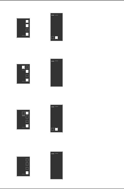
16. Pentium® !!! 800 / 100MHz FSB
ON
 4 3 2 1
SW2
ON

 1
1 
 2
2 
 3
3 
 4
4 

 5
5 


 6
6
SW1
17. Pentium® !!! 850 / 100MHz FSB
ON
 4 3 2 1
SW2
ON

 1
1 
 2
2 
 3
3 
 4
4 

 5
5 


 6
6
SW1
12
6VM7-4E
18. Pentium® !!! 533 / 133MHz FSB
ON
ON
 4 3 2 1
SW2

 1 2 3 4 5 6
SW1
19. Pentium® !!! 600 / 133MHz FSB
ON
ON
 4 3 2 1
SW2

 1 2 3 4 5 6
SW1
20. Pentium® !!! 667 / 133MHz FSB
ON
ON
 4 3 2 1
SW2


 1 2 3 4 5 6
SW1
21. Pentium® !!! 733 / 133MHz FSB
ON
ON
 4 3 2 1
SW2


 1 2 3 4 5 6
SW1
13
22. Pentium® !!! 800 / 133MHz FSB
ON
ON
 4 3 2 1
SW2

 1 2 3 4 5 6
SW1
23. Pentium® !!! 866 / 133MHz FSB
ON
ON
 4 3 2 1
SW2

 1 2 3 4 5 6
SW1
24. Pentium® !!! 933 / 133MHz FSB
ON
ON
 4 3 2 1
SW2


 1 2 3 4 5 6
SW1
25. Pentium® !!! 1GHz / 133MHz FSB
ON
ON
 4 3 2 1
SW2


 1 2 3 4 5 6
SW1
14
6VM7-4E


 Game
Game
Port
|
|
|
|
|
|
|
|
|
|
|
|
|
|
|
|
|
|
|
|
|
|
|
|
|
|
|
|
|
|
|
|
|
|
|
|
|
|
|
|
|
|
|
|
|
|
|
|
|
|
|
|
|
|
|
|
|
|
|
|
|
|
|
|
|
|
|
|
|
|
|
|
|
|
|
|
|
|
|
|
|
|
|
|
|
|
|
|
|
|
|
Line Out |
|
1 |
|
|
MIC In |
|
|
|
|
|
|
|
|
|
|
|||||
|
|
|
|||||||||||
|
|
||||||||||||
Line In/Line Out2
Line Out 1: Line Out or SPDIF (AC ). ”Line Out”,, ”SPDIF Out” (38 ).
Line In: ”Line In”. Creative“Four Speaker” , ( 36 ) ”Line In” ”Line Out 2”, Line Out 1 Line In
.
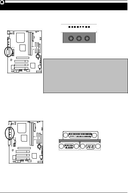
COM A / COM B / LPT
LPT Port
COM A COM B
15
USB1
1 2 3 4 |
5 6 7 8
.
1USB V0
2USB D0-
3USB D0+
5USB V1
6USB D1-
7USB D1+
PS/2 |
PS/2 |
|
|
|
|
PS/2 |
|
|
|
6 |
5 |
|
|
4 |
3 |
|
|
2 |
1 |
|
|
PS/2 |
|
|
|
PS/2 / |
|
|
|
|
|
|
|
1 |
|
|
|
2 |
|
|
|
3 |
|
|
|
4 |
VCC(+5V) |
|
|
5 |
|
|
|
6 |
|
16
6VM7-4E
USB2
|
|
|
|
|
|
|
|
|
|
|
|
|
|
|
|
|
|
|
|
|
|
|
|
|
|
|
|
|
|
|
|
|
|
|
|
|
|
|
|
|
|
|
|
|
|
|
|
|
|
|
|
|
|
|
|
|
|
|
|
|
|
|
|
|
|
|
|
|
|
|
|
|
|
|
|
|
|
|
|
|
|
|
|
|
|
|
|
|
|
|
|
|
|
|
|
|
|
|
|
|
|
|
|
|
2 |
|
|
10 |
1 |
+5V-SB |
|||||||||
|
|
|
|
|
|
|
|
|
|
|
|
|
|
|
|
|
|
|
|
|
|
|
|
|
|
|
|||||||||||||
|
|
|
|
|
|
|
|
|
|
|
|
|
|
|
|
|
|
2 |
|
||||||||||||||||||||
|
|
|
|
|
|
|
|
|
|
|
|
|
|
|
|
|
|
|
|
|
|
|
|
|
|
|
|
|
|
|
|
|
|
|
|
|
|
||
|
|
|
|
|
|
|
|
|
|
|
|
|
|
|
|
|
|
|
|
|
|
|
|
|
|
|
|
|
|
|
|
|
|
|
|
|
|
||
|
|
|
|
|
|
|
|
|
|
|
|
|
|
|
|
|
|
|
|
|
|
|
|
|
|
|
|
|
|
|
|
|
|
|
|
|
|
|
|
|
|
|
|
|
|
|
|
|
|
|
|
|
|
|
|
|
|
|
|
|
|
|
|
|
|
|
|
|
|
|
|
|
|
|
|
|
|
3 |
USB D2- |
|
|
|
|
|
|
|
|
|
|
|
|
|
|
|
|
|
|
|
|
|
|
|
|
|
1 |
|
|
9 |
|
4 |
|
||||||||
|
|
|
|
|
|
|
|
|
|
|
|
|
|
|
|
|
|
|
|
|
|
|
|
|
|
|
|
|
|
|
|
|
|
|
|
|
|
5 |
USB D2+ |
|
|
|
|
|
|
|
|
|
|
|
|
|
|
|
|
|
|
|
|
|
|
|
|
|
|
|
|
|
|
|
|
|
|
|
|
|
|
6 |
USB D3+ |
|
|
|
|
|
|
|
|
|
|
|
|
|
|
|
|
|
|
|
|
|
|
|
|
|
|
|
|
|
|
|
|
|
|
|
|
|
|
||
|
|
|
|
|
|
|
|
|
|
|
|
|
|
|
|
|
|
|
|
|
|
|
|
|
|
|
|
|
|
|
|
|
|
|
|
|
|
||
|
|
|
|
|
|
|
|
|
|
|
|
|
|
|
|
|
|
|
|
|
|
|
|
|
|
|
|
|
|
|
|
|
|
|
|
|
|
7 |
|
|
|
|
|
|
|
|
|
|
|
|
|
|
|
|
|
|
|
|
|
|
|
|
|
|
|
|
|
|
|
|
|
|
|
|
|
|
|
||
|
|
|
|
|
|
|
|
|
|
|
|
|
|
|
|
|
|
|
|
|
|
|
|
|
|
|
|
|
|
|
|
|
|
|
|
|
|
||
|
|
|
|
|
|
|
|
|
|
|
|
|
|
|
|
|
|
|
|
|
|
|
|
|
|
|
|
|
|
|
|
|
|
|
|
|
|
|
|
|
|
|
|
|
|
|
|
|
|
|
|
|
|
|
|
|
|
|
|
|
|
|
|
|
|
|
|
|
|
|
|
|
|
|
|
|
|
8 |
USB D3- |
|
|
|
|
|
|
|
|
|
|
|
|
|
|
|
|
|
|
|
|
|
|
|
|
|
|
|
|
|
|
|
|
|
|
|
|
|
|
||
|
|
|
|
|
|
|
|
|
|
|
|
|
|
|
|
|
|
|
|
|
|
|
|
|
|
|
|
|
|
|
|
|
|
|
|
|
|
|
|
|
|
|
|
|
|
|
|
|
|
|
|
|
|
|
|
|
|
|
|
|
|
|
|
|
|
|
|
|
|
|
|
|
|
|
|
|
|
|
|
|
|
|
|
|
|
|
|
|
|
|
|
|
|
|
|
|
|
|
|
|
|
|
|
|
|
|
|
|
|
|
|
|
|
|
|
|
|
9 |
|
|
|
|
|
|
|
|
|
|
|
|
|
|
|
|
|
|
|
|
|
|
|
|
|
|
|
|
|
|
|
|
|
|
|
|
|
|
|
|
|
|
|
|
|
|
|
|
|
|
|
|
|
|
|
|
|
|
|
|
|
|
|
|
|
|
|
|
|
|
|
|
|
|
|
|
|
|
|
10 |
+5V-SB |
|
|
|
|
|
|
|
|
|
|
|
|
|
|
|
|
|
|
|
|
|
|
|
|
|
|
|
|
|
|
|
|
|
|
|
|
|
|
|
|
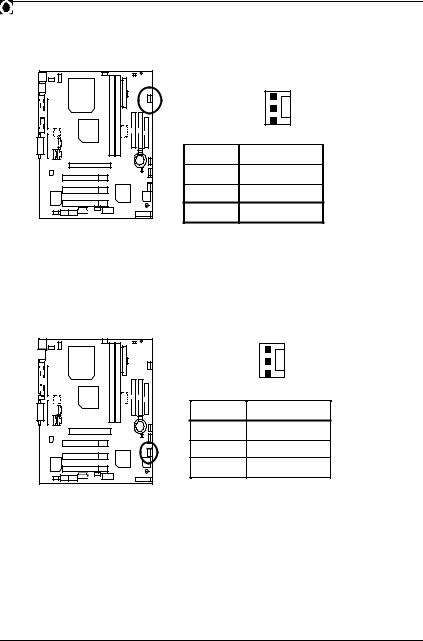
JP16: CPU
|
|
|
|
|
|
|
|
|
|
|
|
|
|
|
|
|
|
|
|
|
|
|
|
|
|
|
1 |
|
|
|
|
|
|
|
|
|
|
|
|
|
|
|
|
|
|
|
|
|
|
|
|
|
|
|
|
|
|
|
|
|
|
|
|
|
|
|
|
|
|
|
|
|
|
|
|
|
|
|
|
|
|
|
|
|
|
|
|
|
|
|
|
|
|
|
|
|
|
|
|
|
|
|
|
|
|
|
|
|
|
|
|
|
|
|
|
|
|
|
|
|
|
|
|
|
|
|
|
|
|
|
|
|
|
|
|
|
|
|
|
|
|
|
|
|
|
|
|
|
|
|
|
|
|
|
|
|
|
|
|
|
|
|
|
|
|
|
|
|
|
|
|
|
|
|
|
|
|
|
|
|
|
|
|
|
|
|
|
|
|
|
|
|
|
|
|
|
|
|
|
|
|
|
|
|
|
|
|
|
|
|
|
|
|
|
|
|
|
|
|
|
|
|
|
|
|
|
|
|
|
|
|
|
|
|
|
|
|
|
|
|
|
|
|
|
|
|
|
|
|
|
|
|
|
|
|
|
|
|
|
|
|
|
|
|
|
|
|
|
|
|
|
|
|
|
|
|
|||
|
|
|
|
|
|
|
|
|
|
|
|
|
|
|
|
|
|||||||||||
|
|
|
|
|
|
|
|
|
|
|
|
|
|
|
|
|
|
|
|
|
1 |
|
|||||
|
|
|
|
|
|
|
|
|
|
|
|
|
|
|
|
|
|
|
|
|
|
|
|
|
|
2 |
+12V |
|
|
|
|
|
|
|
|
|
|
|
|
|
|
|
|
|
|
|
|
|
|||||||
|
|
|
|
|
|
|
|
|
|
|
|
|
|
|
|
|
|
|
|
|
|
3 |
|
||||
|
|
|
|
|
|
|
|
|
|
|
|
|
|
|
|
|
|
|
|
|
|
|
|
|
|
|
|
|
|
|
|
|
|
|
|
|
|
|
|
|
|
|
|
|
|
|
|
|
|
|
|
|
|
|
|
|
|
|
|
|
|
|
|
|
|
|
|
|
|
|
|
|
|
|
|
|
|
|
|
|
|
|
|
|
|
|
|
|
|
|
|
|
|
|
|
|
|
|
|
|
|
|
|
|
|
|
|
|
|
|
|
17
|
|
JP15: |
|
|
1 |
|
|
1 |
|
2 |
+12V |
3 |
|
JP2: |
|
|
1 |
|
|
1 |
|
2 |
+12V |
3 |
|
18
6VM7-4E
ATX
|
|
|
|
|
|
|
|
|
|
|
|
|
|
|
|
|
|
|
|
|
|
|
|
|
|
|
|
|
|
|
|
|
|
|
|
|
|
|
|
|
|
|
|
|
|
|
|
|
|
|
|
|
|
|
|
|
|
|
10 |
20 |
|
3,5,7,13, |
|
||||
|
|
|
|
|
|
|
|
|
|
|
|
|
|
|
|
|
|
|
|
|
|
|
|
|
|
|
|
|
|
|
|
15-17 |
|
|
|
|
|
|
|
|
|
|
|
|
|
|
|
|
|
|
|
|
|
|
|
|
|
|
|
|
|
|
|
|
|
1,2,11 |
3.3V |
|
|
|
|
|
|
|
|
|
|
|
|
|
|
|
|
|
|
|
|
|
|
|
|
|
|
|
|
|
|
|
|
||
|
|
|
|
|
|
|
|
|
|
|
|
|
|
|
|
|
|
|
|
|
|
|
|
|
|
|
|
|
|
|
|
4,6,19,20 |
VCC |
|
|
|
|
|
|
|
|
|
|
|
|
|
|
|
|
|
|
|
|
|
|
|
|
|
|
|
|
|
|
|
|
|
|
|
|
|
|
|
|
|
|
|
|
|
|
|
|
|
|
|
|
|
|
|
|
|
|
|
|
|
|
|
|
|
|
10 |
+12V |
|
|
|
|
|
|
|
|
|
|
|
|
|
|
|
|
|
|
|
|
|
|
|
|
|
|
|
|
|
|
|
|
||
|
|
|
|
|
|
|
|
|
|
|
|
|
|
|
|
|
|
|
|
|
|
|
|
|
|
|
|
|
|
|
|
12 |
-12V |
|
|
|
|
|
|
|
|
|
|
|
|
|
|
|
|
|
|
|
|
|
|
|
|
|
|
|
|
|
|
|
|
|
|
|
|
|
|
|
|
|
|
|
|
|
|
|
|
|
|
|
|
|
|
|
|
|
|
|
|
|
|
|
|
|
|
18 |
-5V |
|
|
|
|
|
|
|
|
|
|
|
|
|
|
|
|
|
|
|
|
|
|
|
|
|
|
8 |
|
||||||
|
|
|
|
|
|
|
|
|
|
|
|
|
|
|
|
|
|
|
|
|
|
|
1 |
11 |
|
||||||||
|
|
|
|
|
|
|
|
|
|
|
|
|
|
|
|
|
|
|
|
|
|
|
|
|
|
|
|
|
|
|
|
9 |
5V SB stand by+5V |
|
|
|
|
|
|
|
|
|
|
|
|
|
|
|
|
|
|
|
|
|
|
|
|
|
|
|
|
|
|
|
|
14 |
PS-ON(Soft On/Off) |
|
|
|
|
|
|
|
|
|
|
|
|
|
|
|
|
|
|
|
|
|
|
|
|
|
|
|
|
|
|
|
|
||
|
|
|
|
|
|
|
|
|
|
|
|
|
|
|
|
|
|
|
|
|
|
|
|
|
|
|
|
|
|
|
|
||
|
|
|
|
|
|
|
|
|
|
|
|
|
|
|
|
|
|
|
|
|
|
|
|
|
|
|
|
|
|
|
|
||
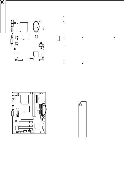
Floppy:
FDD1
19
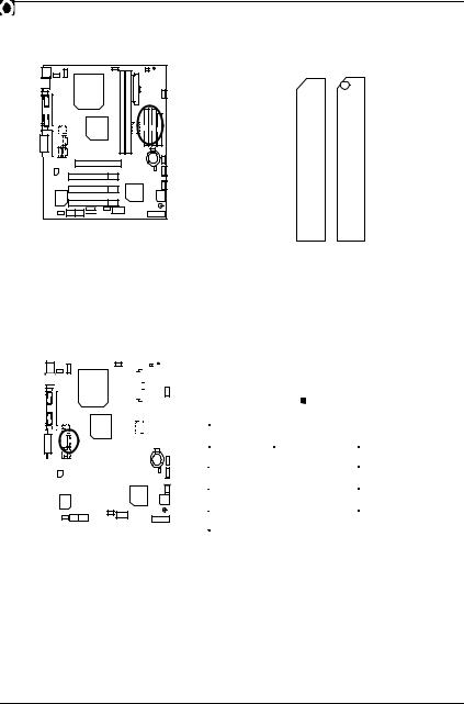
IDE 1 / IDE 2

IDE 1 IDE 2
J7: TEL
|
|
|
|
|
|
|
|
|
|
|
|
|
|
|
|
|
|
|
|
|
|
|
|
|
|
|
1 |
|
|
|
|
|
|
|
|
|
|
|
|
|
|
|
|
|
|
|
|
|
|
|
|
|
|
|
|
|
|
|
|
|
|
|
|
|
|
|
|
|
|
|
|
|
|
|
|
|
|
|
|
|
|
|
|
|
|
|
|
|
|
|
|
|
|
|
|
|
|
|
|
|
|
|
|
|
|
|
|
|
|
|
|
|
|
|
|
|
|
|
|
|
|
|
|
|
|
|
|
|
|
|
|
|
|
|
|
|
|
|
|
|
|
|
|
|
|
|
|
|
|
|
|
|
|
|
|
|
|
|
|
|
|
|
|
|
|
|
|
|
|
|
|
|
|
|
|
|
|
|
|
|
|
|
|
|
|
|
|
|
|
|
|
|
|
|
|||
|
|
|
|
|
|
|
|
|
|
|
|
|
|
|
|
|
||||||||||||||||
|
|
|
|
|
|
|
|
|
|
|
|
|
|
|
|
|
|
|
|
|
|
|
|
|
|
|
|
|
|
|
||
|
|
|
|
|
|
|
|
|
|
|
|
|
|
|
|
|
|
|
|
|
|
|
1 |
Signal-In |
||||||||
|
|
|
|
|
|
|
|
|
|
|
|
|
|
|
|
|
|
|
|
|
2 |
|
||||||||||
|
|
|
|
|
|
|
|
|
|
|
|
|
|
|
|
|
|
|||||||||||||||
|
|
|
|
|
|
|
|
|
|
|
|
|
|
|
|
|
|
|
|
|
|
|
|
|
|
|||||||
|
|
|
|
|
|
|
|
|
|
|
|
|
|
|
|
|
|
|
|
|
|
|
|
|
|
|
|
|
|
|
|
|
|
|
|
|
|
|
|
|
|
|
|
|
|
|
|
|
|
|
|
|
|
|
|
|
|
|
|
|
|||||
|
|
|
|
|
|
|
|
|
|
|
|
|
|
|
|
|
|
|
|
|
|
|
|
|
|
3 |
|
|||||
|
|
|
|
|
|
|
|
|
|
|
|
|
|
|
|
|
|
|
|
|
|
|
|
|
|
|
|
|
|
|
|
|
|
|
|
|
|
|
|
|
|
|
|
|
|
|
|
|
|
|
|
|
|
|
|
|
|
4 |
Signal-Out |
||||||
|
|
|
|
|
|
|
|
|
|
|
|
|
|
|
|
|
|
|
|
|
|
|
||||||||||
|
|
|
|
|
|
|
|
|
|
|
|
|
|
|
|
|
|
|
|
|||||||||||||
|
|
|
|
|
|
|
|
|
|
|
|
|
|
|
|
|
|
|
|
|
|
|
|
|
|
|||||||
20
 Loading...