


|
|
|
|
FCC Compliance Statement: |
|
|
|
|
||||
|
This equipment has been tested and found to |
|||||||||||
DECLARATION OF CONFORMITY |
||||||||||||
Per FCC Part 2 Section 2. 1077(a) |
||||||||||||
|
|
|
|
comply with limits for a Class B digital device, |
||||||||
Responsible Party Name: G.B.T. INC. |
pursuant to Part 15 of the FCC rules. These |
|||||||||||
limits are |
designed |
to |
provide |
reasonable |
||||||||
Address: 18305 Valley Blvd., Suite#A |
||||||||||||
|
LA Puent, CA 91744 |
protection |
against |
harmful |
interference |
in |
||||||
Phone/Fax No: (818) 854-9338/ (818) 854-9339 |
||||||||||||
hereby declares that the product |
|
|
residential |
installations. |
This |
equipment |
||||||
Product Name: Mother Board |
|
|
||||||||||
|
|
generates, |
uses, and |
can |
radiate |
radio |
||||||
Model Number: GA-6RX |
|
|
||||||||||
Conforms to the following specifications: |
frequency energy, and if not installed and used |
|||||||||||
|
|
|
|
|||||||||
FCC Part 15, Subpart B, Section 15.107(a) and Section 15.109(a), |
in accordance with the instructions, may cause |
|||||||||||
Class B Digital Device |
|
|
||||||||||
Supplementary Information: |
|
|
||||||||||
|
|
harmful interference |
to radio |
communications. |
||||||||
This device complies with part 15 of the FCC Rules. Operation is subject to the |
||||||||||||
following two conditions: (1) |
This device may not cause harmful |
|||||||||||
and (2) this device must accept any inference received, including |
However, there is no guarantee that interference |
|||||||||||
that may cause undesired operation. |
|
|
||||||||||
Representative Person's Name: |
ERIC LU |
|||||||||||
will not occur in a particular installation. If this |
||||||||||||
Signature: |
|
EricLu |
|
|||||||||
Date: |
Jan.10, 2001 |
equipment does cause interference to radio or |
||||||||||
|
|
|
|
|||||||||
|
|
|
|
television |
equipment |
reception, which |
can |
be |
||||
determined by turning the equipment off and on, the user is encouraged to try to correct the interference by one or more of the following measures:
-Reorient or relocate the receiving antenna
-Move the equipment away from the receiver
-Plug the equipment into an outlet on a circuit different from that to which the receiver is connected
-Consult the dealer or an experienced radio/television technician for additional suggestions
You are cautioned that any change or modifications to the equipment not expressly approve by the party responsible for compliance could void Your authority to operate such equipment.
This device complies with Part 15 of the FCC Rules. Operation is subjected to the following two conditions 1) this device may not cause harmful interference and 2) this device must accept any interference received, including interference that may cause undesired operation.

Declaration of Conformity
We, Manufacturer/Importer
(full address)
G.B.T. Technology Träding GMbH
Ausschlager Weg 41, 1F, 20537 Hamburg, Germany
declare that the product
( description of the apparatus, system, installation to which it refers)
Mother Board
GA-6RX
is in conformity with
(reference to the specification under which conformity is declared) in accordance with 89/336 EEC-EMC Directive
EN 55011 |
Limits and methods of measurement |
|
of radio disturbance characteristics of |
|
industrial, scientific and medical (ISM |
|
high frequency equipment |
EN55013 |
Limits and methods of measurement |
|
of radio disturbance characteristics of |
|
broadcast receivers and associated |
|
equipment |
EN 55014 |
Limits and methods of measurement |
|
of radio disturbance characteristics of |
|
household electrical appliances, |
|
portable tools and similar electrical |
|
apparatus |
EN 55015 |
Limits and methods of measurement |
|
of radio disturbance characteristics of |
|
fluorescent lamps and luminaries |
EN 55020 |
Immunity from radio interference of |
|
broadcast receivers and associated |
|
equipment |
EN 55022 |
Limits and methods of measurement |
|
of radio disturbance characteristics of |
|
information technology equipment |
DIN VDE 0855 |
Cabled distribution systems; Equipment |
part 10 |
for receiving and/or distribution from |
part 12 |
sound and television signals |
 CE marking
EN 61000-3-2* |
Disturbances in supply systems caused |
EN60555-2 |
by household appliances and similar |
|
electrical equipment “Harmonics” |
EN61000-3-3* |
Disturbances in supply systems caused |
EN60555-3 |
by household appliances and similar |
|
electrical equipment “Voltage fluctuations” |
EN 50081-1 |
Generic emission standard Part 1: |
|
Residual, commercial and light industry |
EN 50082-1 |
Generic immunity standard Part 1: |
|
Residual, commercial and light industry |
EN 55081-2 |
Generic emission standard Part 2: |
|
Industrial environment |
EN 55082-2 |
Generic immunity standard Part 2: |
|
Industrial environment |
ENV 55104 |
Immunity requirements for household |
|
appliances tools and similar apparatus |
EN 50091- 2 |
EMC requirements for uninterruptible |
|
power systems (UPS) |
 (EC conformity marking)
The manufacturer also declares the conformity of above mentioned product with the actual required safety standards in accordance with LVD 73/23 EEC
EN 60065 |
Safety requirements for mains operated |
EN 60950 |
Safety for information technology equipment |
||||
|
electronic and related apparatus for |
|
|
including electrical business equipment |
|||
|
household and similar general use |
|
|
|
|
|
|
EN 60335 |
Safety of household and similar |
|
EN 50091-1 |
General and Safety requirements for |
|||
|
electrical appliances |
|
|
uninterruptible power systems (UPS) |
|||
|
|
Manufacturer/Importer |
|
|
|
|
|
|
|
|
|
Signature : |
Rex Lin |
||
|
(Stamp) |
Date : |
Jan. 10, 2001 |
Name : |
|
Rex Lin |
|
6RX Series
Socket 370 Processor Motherboard
USER'S MANUAL
Socket 370 Processor Motherboard
REV 1.0 Third Edition
R-10-03-010420

How This Manual Is Organized
This manual is divided into the following sections:
Manual revision information
Product item list
Product information & specification
Instructions on CPU & Memory Installation
Product performance & block diagram
Instructions on STR & Dual BIOS installation
Four Speaker & SPDIF introduction @BIOS™ & EasyTuneIII™ introduction Instructions on Raid
Instructions on setting up the BIOS software
Document equipment used for after sales service
General reference

Table Of Content
Revision History |
P.1 |
Item Checklist |
P.2 |
Features Summary |
P.3 |
6RX Series Motherboard Layout |
P.5 |
Installation Guide |
P. 6 |
Page Index for Connectors / Panel and Jumper Definition |
P.15 |
Performance List |
P.39 |
Block Diagram |
P.40 |
Suspend to RAM Installation |
P.41 |
Dual BIOS Introduction (Optional) |
P.47 |
Four Speaker & SPDIF Introduction (Optional) |
P.54 |
@BIOSTM Introduction |
P.60 |
EasyTuneIIITM Introduction |
P.61 |
Raid Introduction |
P.63 |
Page Index for BIOS Setup |
P.86 |
Technical Support / RMA Sheet |
P.115 |
Appendix |
P.116 |
|
|

6RX Series Motherboard
Revision History
Revision |
Revision Note |
Date |
1.0 |
Initial release of the 6RX Series motherboard user’s |
Jan. 2001 |
|
manual. |
|
1.0 |
Second release of the 6RX Series motherboard user’s |
Feb. 2001 |
|
manual. |
|
1.0 |
Third release of the 6RX Series motherboard user’s |
Apr. 2001 |
|
manual. |
|
The author assumes no responsibility for any errors or omissions that may appear in this document nor does the author make a commitment to update the information contained herein. Third-party brands and names are the property of their respective owners.
Apr. 20, 2001 Taipei, Taiwan, R.O.C
1

Item Checklist
Item Checklist
;The 6RX Series Motherboard
;Cable for IDE / Floppy device
;CD (TUCD) for motherboard utilities
;6RX Series User’s Manual
;Front USB Cable
2
6RX Series Motherboard
Features Summary
Form factor |
y |
30.5 cm x 24.5 cm ATX size form factor, 4 layers PCB. |
Motherboard |
y |
6RX series includes 6RX, 6RX-1, 6RX-L |
CPU |
y |
Socket 370 processor |
|
|
Intel Pentium !!! 100/133MHz FSB, FC-PGA |
|
|
Intel CeleronTM 66/100MHz FSB, FC-PGA |
|
|
VIA Cyrix III 100/133MHz FSB, CPGA |
|
|
(Please make sure your CPU is mass production version) |
|
y L2 cache depend on CPU |
|
Chipset |
y |
VT8633 (Apollo Pro266) |
|
y |
VT8233 |
Clock Generator |
y |
ICW W250-03 |
|
y 66/100/133 MHz system bus speeds (PCI 33MHz) |
|
|
y 115/124/140/145/150 MHz system bus speeds |
|
|
|
(reserved) |
Memory |
y |
4 184-pin DDR DIMM sockets |
|
y Supports PC1600 DDR or PC2100 DDR SDRAM |
|
|
y Supports up to 4GB DRAM (Max) |
|
|
y Supports only 2.5V DDR SDRAM |
|
I/O Control |
y |
ITE IT8705 F |
Slots |
y |
1 Universal AGP Pro slot 4X/2X (1.5V/3.3V) device |
|
|
support |
|
y 5 PCI slots support 33MHz & PCI 2.2 compliant |
|
|
y 1 AMR (Audio Modem Riser) slot |
|
On-Board IDE |
y |
IDE 1and IDE 2 Supports PIO mode 3, 4 UDMA 33 / |
|
|
ATA 66 / ATA100 IDE & ATAPI CD-ROM |
y IDE 3 and IDE 4 Compatible with Raid, Ultra ATA100, Ultra ATA66, Ultra ATA33, EIDE
y 4 IDE bus master IDE ports for up to 8 ATAPI devices To be continued…
3

|
|
|
Features Summary |
|
|
On-Board |
y |
1 Floppy port supports 2 FDD with 360K, 720K, 1.2M, |
|
|
|
|||
|
Peripherals |
|
1.44M and 2.88M bytes |
|
|
|
y 1 Parallel port supports Normal/EPP/ECP mode |
|
|
|
|
y 2 Serial ports (COM A & COM B) |
|
|
|
|
y 6 USB ports (Back USB*2, Front USB*2, USB AGP*1, |
|
|
|
|
|
USB AMR*1) |
|
|
|
y 1 IrDA connector for IR/CIR |
|
|
|
Hardware Monitor |
y |
CPU/Power Fan Revolution detect |
|
|
|
y |
CPU Fan Control |
|
|
|
y CPU temperature detect (This function is available on CPU |
|
|
|
|
|
with Thermal Diode) |
|
|
|
y |
System Voltage Detect |
|
|
|
y |
Chassis Intrusion Detect |
|
|
|
y Display Actual Current Voltage |
|
|
|
On-Board Sound |
y |
Creative CT5880 sound (Optional) |
|
|
|
y |
AC’97 CODEC |
|
|
|
y Line In/Line Out/Mic In/AUX In (Optional)/CD In/ |
|
|
|
|
|
TEL (Optional)/Game Port |
|
|
|
y SPDIF and Four Speaker (Optional) |
|
|
|
On-Board LAN |
y |
MAC Build in VT8233 |
|
|
|
y LSI 80223 PHY (Optional) |
|
|
|
PS/2 Connector |
y |
PS/2 Keyboard interface and PS/2 Mouse interface |
|
|
BIOS |
y |
Licensed AMI BIOS, 2M bit Flash ROM |
|
|
|
y Support Dual BIOS (Optional) |
|
|
|
Additional Features |
y |
Internal/External Modem wake up |
|
|
|
y STR (Suspend-To-RAM) |
|
|
|
|
y |
Wake On LAN |
|
|
|
y PS/2 Keyboard any key power on |
|
|
|
|
y PS/2 Mouse power on |
|
|
|
|
y System after AC back |
|
|
|
|
y Poly fuse for keyboard, USB, game port overcurrent |
|
|
|
|
|
protection |
|
|
|
y |
USB KB/MS wake up from S3 |
|
|
|
y |
Support @BIOS™ and EasyTuneIII™ |
|
4

6RX Series Motherboard
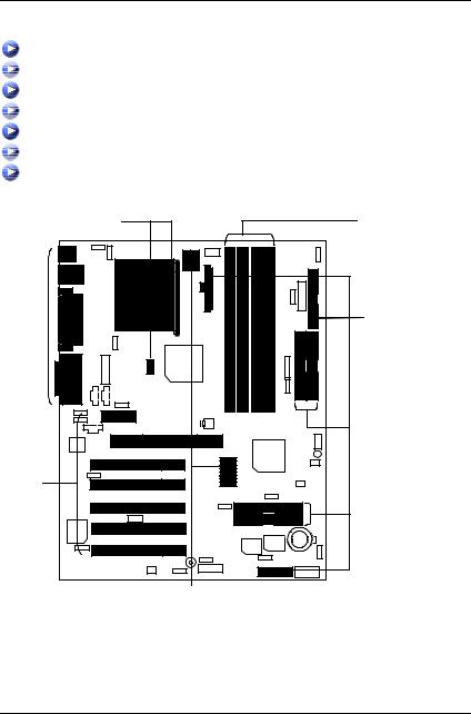
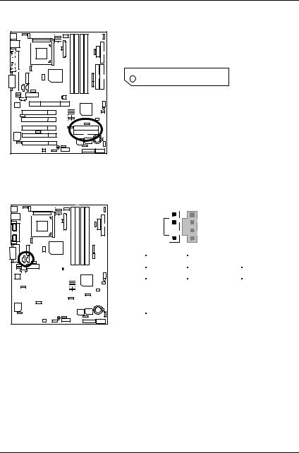
6RX Series Motherboard Layout
PS/2
|
|
USB |
LAN |
||
|
|
|
|
|
|
|
|
|
|
|
|
|
|
|
|
|
|
|
|
|
COM A |
LPT |
|
|
|
|
|
||
|
|
|
|
||
|
|
|
COM B |
|
|
|
|
|
|
|
|
|
|
|
|
|
|
|
|
|
|
|
|
|
|
|
|
GAME & Audio |
|
|
|
|
|
|
|
|
|
|
|
|
|
JP4 

JP3 

JP9 |
JP17 |
|
|
|
|
JP13 |
|
|
J10 |
|
|
|
|
|
|
|
SW4 |
|
|
|
ATXPOWER |
JP19 |
FLOPPY |
|
|
|
|
|
|
|
J12 |
Socket 370
CPU


 JP21
JP21
J13
JP2 |
VT8633 |
|
J1 |
||
|
|
|
|
|
J4 |
|
J5 |
|
|
|
|
|
|
DIMM1 |
|
DIMM2 |
DIMM3 |
|
DIMM4 |
|
|
|
|
|
|
||||||
|
|
|
|
|
|
|
|
|
|
|
|
|
|
|
|
|
|
|
||||||||||||
|
|
|
|
|
|
|
|
|
|
|
|
|
|
|
|
|
|
|
|
|
|
|
||||||||
|
|
|
|
|
|
|
|
|
|
|
|
|
|
|
|
|
|
|
|
|
|
|
||||||||
|
|
|
|
|
|
|
|
|
|
|
|
|
|
|
|
|
|
|
|
|
|
JP22 |
|
|
|
|||||
|
|
|
|
|
|
|
|
|
|
|
|
|
JP5 |
|
|
|
|
|
|
|
|
|
IDE1 |
IDE2 |
||||||
|
|
|
|
|
|
|
|
|
|
|
|
|
|
|
|
|
|
|
|
|
|
|
|
|
|
|
|
|||
|
|
|
|
|
|
|
|
AMR |
|
|
|
|
|
|
|
|
|
|
|
|
|
|
|
|
|
|
|
|||
|
|
|
|
|
|
|
|
J3 |
|
|
|
|
|
CN11 |
|
6RX |
|
|
|
|
|
|
J11 |
|||||||
AC97 |
AGP2 |
|
|
|
|
|
|
|
|
VT8233 |
LED1 |
|
PCI1 |
|
JP7 |
|
|
|
|
JP30 |
|
|
|
|
PCI2 |
|
JP8 |
|
SW1 |
JP14 |
|
|
|
|
|
|
JP15 |
|
|
PCI3 |
|
IDE4 |
|
|
J9 |
|
|
|
|
IDE3 |
Creative |
PCI4 |
|
|
|
|
|
CT5880 |
|
|
|
|
BACK Up |
BAT1 |
|
|
|
|
MAIN |
||
|
|
|
|
BIOS |
|
|
|
PCI5 |
|
|
BIOS |
|
|
JP12 |
BZ1 |
JP16 |
|
JP1 |
||
|
|
JP11 |
||||
|
J8 |
|
|
|
CN9 |
|
|
JP6 |
|
|
|
||
|
|
|
J7 |
|
|
|
|
|
|
J14 |
|
|
|
|
|
|
|
|
|
5

Installation Guide
Installation Guide
Getting Started
WARNING!
Computer motherboards and expansion cards contain very delicate Integrated Circuit (IC) chips. To protect them against damage from static electricity, you should follow some precautions whenever you work on your computer.
1.Unplug your computer when working on the inside.
2.Use a grounded wrist strap before handling computer components. If you do not have one, touch both of your hands to a safely grounded object or to a metal object, such as the power supply case.
3.Hold components by the edges and try not touch the IC chips, leads or connectors, or other components.
4.Place components on a grounded antistatic pad or on the bag that came with the components whenever the components are separated from the system.
5.Ensure that the ATX power supply is switched off before you plug in or remove the ATX power connector on the motherboard.
Installing the motherboard to the chassis…
If the motherboard has mounting holes, but they don’t line up with the holes on the base and there are no slots to attach the spacers, do not become alarmed you can still attach the spacers to the mounting holes. Just cut the bottom portion of the spacers (the spacer may be a little hard to cut off, so be careful of your hands). In this way you can still attach the motherboard to the base without worrying about short circuits. Sometimes you may need to use the plastic springs to isolate the screw from the motherboard PCB surface, because the circuit wire may be near by the hole. Be careful, don’t let the screw contact any printed circuit write or parts on the PCB that are near the fixing hole, otherwise it may damage the board or cause board malfunctioning.
6
6RX Series Motherboard
To set up your computer, you must complete the following steps:
Step 1 - Set system jumpers
Step 2- Install the Central Processing Unit (CPU) Step 3-Install memory modules
Step 4-Install expansion cards
Step 5-Connect ribbon cables, cabinet wires, and power supply Step 6-Set up BIOS software
Step 7-Install supporting software tools
Step 2 |
Step 3 |
Step 5 |
Step 5 |
Step 4 |
|
Step 1
7

Installation Guide
CPU Speed Setup
The system bus frequency can be switched at 66MHz - 166MHz and Auto by adjusting SW 1. (The frequency ratio depend on CPU).
SW1 Select the System Speed at 66MHz - 166MHz and Auto. |
|
|
O: ON, X: OFF |
|||||||
|
|
|
|
|
|
|
|
|
|
|
CPU |
AGP |
1 |
2 |
3 |
4 |
|
5 |
6 |
7 |
8 |
|
|
|
|
|
|
|
|
|
|
|
Auto |
66.67 |
X |
X |
X |
X |
|
X |
X |
X |
X |
|
|
|
|
|
|
|
|
|
|
|
66.8 |
66.8 |
O |
O |
O |
X |
|
X |
O |
O |
O |
|
|
|
|
|
|
|
|
|
|
|
75 |
75 |
O |
O |
O |
X |
|
O |
X |
X |
O |
78 |
78 |
O |
O |
O |
X |
|
O |
O |
X |
X |
|
|
|
|
|
|
|
|
|
|
|
90 |
60 |
O |
O |
X |
X |
|
O |
O |
O |
X |
|
|
|
|
|
|
|
|
|
|
|
100.2 |
66.8 |
O |
O |
X |
X |
|
X |
O |
O |
X |
105 |
70 |
O |
O |
X |
X |
|
O |
O |
O |
O |
|
|
|
|
|
|
|
|
|
|
|
110 |
73.3 |
O |
O |
X |
X |
|
X |
X |
X |
O |
|
|
|
|
|
|
|
|
|
|
|
115 |
76.67 |
O |
O |
X |
X |
|
X |
O |
X |
O |
124 |
62 |
O |
X |
X |
O |
|
O |
O |
X |
X |
|
|
|
|
|
|
|
|
|
|
|
130 |
65 |
O |
X |
X |
O |
|
O |
O |
X |
O |
|
|
|
|
|
|
|
|
|
|
|
133.4 |
66.7 |
O |
X |
X |
X |
|
X |
O |
X |
X |
136 |
68 |
O |
X |
X |
O |
|
O |
O |
O |
X |
|
|
|
|
|
|
|
|
|
|
|
140 |
70 |
O |
X |
X |
O |
|
O |
O |
O |
O |
|
|
|
|
|
|
|
|
|
|
|
145 |
72.5 |
O |
X |
X |
O |
|
X |
X |
X |
X |
150 |
75 |
O |
X |
X |
O |
|
X |
X |
X |
O |
|
|
|
|
|
|
|
|
|
|
|
160 |
80 |
O |
X |
X |
O |
|
X |
X |
O |
X |
|
|
|
|
|
|
|
|
|
|
|
166 |
83 |
O |
X |
X |
O |
|
X |
X |
O |
O |
¼We recommend you to setup your system speed to Auto. CPU Vcore Voltage Setup
SW4 Select the CPU Voltage at 1.30V – 2.05V and Auto. |
|
|
O: ON, X: OFF |
|||||
|
|
|
|
|
|
|
|
|
Vcore |
1 |
2 |
3 |
|
4 |
5 |
|
6 |
|
|
|
|
|
|
|
|
|
1.3 |
X |
X |
X |
|
X |
O |
|
O |
|
|
|
|
|
|
|
|
|
1.35 |
O |
X |
X |
|
X |
O |
|
O |
|
|
|
|
|
|
|
|
|
1.4 |
X |
O |
X |
|
X |
O |
|
O |
1.45 |
O |
O |
X |
|
X |
O |
|
O |
|
|
|
|
|
|
|
|
|
8

6RX Series Motherboard
Vcore |
1 |
2 |
3 |
4 |
5 |
6 |
|
|
|
|
|
|
|
1.5 |
X |
X |
O |
X |
O |
O |
|
|
|
|
|
|
|
1.55 |
O |
X |
O |
X |
O |
O |
|
|
|
|
|
|
|
1.6 |
X |
O |
O |
X |
O |
O |
|
|
|
|
|
|
|
1.65 |
O |
O |
O |
X |
O |
O |
|
|
|
|
|
|
|
1.7 |
X |
X |
X |
O |
O |
O |
|
|
|
|
|
|
|
1.75 |
O |
X |
X |
O |
O |
O |
|
|
|
|
|
|
|
1.8 |
X |
O |
X |
O |
O |
O |
|
|
|
|
|
|
|
1.85 |
O |
O |
X |
O |
O |
O |
|
|
|
|
|
|
|
1.9 |
X |
X |
O |
O |
O |
O |
|
|
|
|
|
|
|
1.95 |
O |
X |
O |
O |
O |
O |
|
|
|
|
|
|
|
2 |
X |
O |
O |
O |
O |
O |
|
|
|
|
|
|
|
2.05 |
O |
O |
O |
O |
O |
O |
|
|
|
|
|
|
|
Auto |
X |
X |
X |
X |
X |
X |
|
|
|
|
|
|
|
¼We recommend you to setup your vcore to Auto.
9
Installation Guide
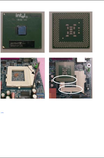
CPU Installation
Please make sure the CPU type and speed is supported by your motherboard.
CPU Top View
Socket Actuation Lever
1.Pull the lever out and lift it up.
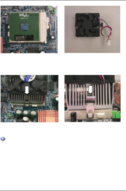
 CPU Heat Sink Installation:
CPU Bottom View
2.The notched corner should point toward the end of the lever. The CPU will only fit in the orientation as shown.
Beware: Please check that the heat sink is in good contact with the CPU before you turn on your system. Poor contact will cause over heat with might cause damage to your processor!
10
6RX Series Motherboard
3.Align CPU and insert it |
4.Use compliant fan approved by Intel. |
(Please refer to your heatsink installation |
|
manual for application of thermal grease to |
|
provide better heat conduction between your |
|
CPU and heatsink.) |
|
5.Hook one end of the cooler bracket to the CPU socket.
6. Hook the other end of the cooler bracket to the CPU socket.
(Please refer to the cooler’s installation manual for detailed installation steps)
11

Installation Guide
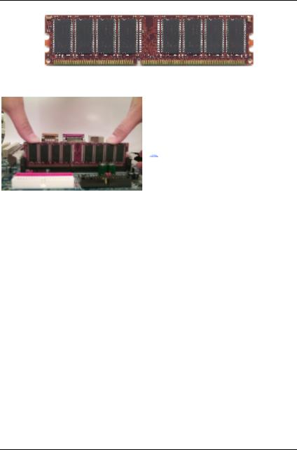
Memory Installation
The motherboard has 4 dual inline memory module (DIMM) sockets. The BIOS will automatically detects memory type and size. To install the memory module, just push it vertically into the DIMM Slot .The DIMM module can only fit in one direction due to the notch. Memory size can vary between sockets.
Total Memory Sizes With Registered DDR DIMM
Devices used on DIMM
64 Mbit (4Mx4x4 banks) 64 Mbit (2Mx8x4 banks) 64 Mbit
(1Mx16x4 banks)
128 Mbit (8Mx4x4 banks)
128 Mbit (4Mx8x4 banks) 128 Mbit (2Mx16x4 banks)
256 Mbit (16Mx4x4 banks)
256 Mbit (8Mx8x4 banks) 256 Mbit (4Mx16x4 banks) 512 Mbit (16Mx8x4 banks)
512 Mbit (8Mx16x4 banks)
1 DIMM |
2 DIMMs |
3 DIMMs |
4 DIMMs |
x64/x72 |
x64/x72 |
x64/x72 |
x64/x72 |
256 MBytes |
512 MBytes |
768 MBytes |
1 GBytes |
128 MBytes |
256 MBytes |
384 MBytes |
512 MBytes |
64 MBytes |
128 MBytes |
192 MBytes |
256 MBytes |
512 MBytes |
1 GBytes |
1.5 GBytes |
2 GBytes |
256 MBytes |
512 MBytes |
768 MBytes |
1 GBytes |
128 MBytes |
256 MBytes |
384 MBytes |
512 MBytes |
1 GBytes |
2 GBytes |
3 GBytes |
4 GBytes |
512 MBytes |
1 GBytes |
1.5 GBytes |
2 GBytes |
256 MBytes |
512 MBytes |
768 MBytes |
1 GBytes |
1 GBytes |
2 GBytes |
3 GBytes |
4 GBytes |
512 MBytes |
1 GBytes |
1.5 GBytes |
2 GBytes |
12
6RX Series Motherboard
Total Memory Sizes With Unbuffered DDR DIMM
Devices used on DIMM |
1 DIMM |
2 DIMMs |
3 DIMMs |
4 DIMMs |
|
x64/x72 |
x64/x72 |
x64/x72 |
x64/x72 |
||
64 Mbit |
|||||
128 MBytes |
256 MBytes |
384 MBytes |
512 MBytes |
||
(2Mx8x4 banks) |
|||||
|
|
|
|
||
64 Mbit |
64 MBytes |
128 MBytes |
192 MBytes |
256 MBytes |
|
(1Mx16x4 banks) |
|||||
|
|
|
|
||
128 Mbit |
256 MBytes |
512 MBytes |
768 MBytes |
1 GBytes |
|
(4Mx8x4 banks) |
|||||
|
|
|
|
||
128 Mbit |
128 MBytes |
256 MBytes |
384 MBytes |
512 MBytes |
|
(2Mx16x4 banks) |
|||||
|
|
|
|
||
256 Mbit |
512 MBytes |
1 GBytes |
1.5 GBytes |
2 GBytes |
|
(8Mx8x4 banks) |
|||||
|
|
|
|
||
256 Mbit |
256 MBytes |
512 MBytes |
768 MBytes |
1 GBytes |
|
(4Mx16x4 banks) |
|||||
|
|
|
|
||
512 Mbit |
1 GBytes |
2 GBytes |
3 GBytes |
4 GBytes |
|
(16Mx8x4 banks) |
|||||
|
|
|
|
||
512 Mbit |
512 MBytes |
1 GBytes |
1.5 GBytes |
2 GBytes |
|
(8Mx16x4 banks) |
|||||
|
|
|
|
13
Installation Guide
DDR
1. The DIMM slot has a notch, so the DIMM memory module can only fit in one direction.
2. Insert the DIMM memory module vertically into the DIMM slot. Then push it down.
3. Close the plastic clip at both edges of the DIMM slots to lock the DIMM module.
 Reverse the installation steps when you wish to remove the DIMM module.
DDR Introduction
Established on the existing SDRAM industry infrastructure, DDR (Double Data Rate) memory is a high performance and cost-effective solution that allows easy adoption for memory vendors, OEMs and system integrators.
DDR memory is a sensible evolutionary solution for the PC industry that builds on the existing SDRAM infrastructure, yet makes awesome advances in solving the system performance bottleneck by doubling the memory bandwidth. DDR SDRAM will offer a superior solution and migration path from existing SDRAM designs due to its availability, pricing and overall market support. PC2100 DDR memory (DDR266) doubles the data rate through reading and writing at both the rising and falling edge of the clock, achieving data bandwidth 2X greater than PC133 when running with the same DRAM clock frequency. With peak bandwidth of 2.1GB per second, DDR memory enables system OEMs to build high performance and low latency DRAM subsystems that are suitable for servers, workstations, high-end PC’s and value desktop SMA systems. With a core voltage of only 2.5 Volts compared to conventional SDRAM's 3.3 volts, DDR memory is a compelling solution for small form factor desktops and notebook applications.
14

6RX Series Motherboard
Page Index for Connectors/Panel and Jumper Definition |
Page |
Connectors |
P.17 |
ATX Power |
P.17 |
COM A / COM B / LPT Port |
P.17 |
CN7 (PS/2 Keyboard & PS/2 Mouse Connector) |
P.18 |
CN9 (Front USB Connector) [Optional] |
P.19 |
CN10 (USB & LAN Connector) [LAN Connector is optional] |
P.18 |
CN11 (ATX +12V Power Connector) [Optional] |
P.25 |
Floppy Port |
P.19 |
Game & Audio Port |
P.20 |
IDE1 (Primary) / IDE2 (Secondary) Port |
P.20 |
IDE3 / IDE4 (Raid / ATA100) Port [Optional] |
P.21 |
J1 (CPU FAN) |
P.25 |
J3 (AUX_IN) [Optional] |
P.22 |
J4 (CD Audio Line In) |
P.21 |
J5 (TEL) [Optional] |
P.22 |
J8 (Ring Power On) |
P.23 |
J9 (Wake On LAN) |
P.26 |
J10 (Power FAN) |
P.24 |
J11 (System FAN) |
P.24 |
J12 (SCR) [Optional] |
P.28 |
J13 (External SMBUS Device Connector) [Optional] |
P.23 |
J14 (IR/CIR) [Optional] |
P.27 |
JP2 (Front Audio) [Optional] |
P.27 |
JP7 / LED1 (STR LED Connector & DIMM LED) |
P.26 |
Panel and Jumper Definition |
P.29 |
BAT 1(Battery) |
P.38 |
J7 (2x11 pins jumper) |
P.29 |
JP1 (Clear CMOS Function) |
P.30 |
JP3 (SPDIF Auto Detection) [Optional] |
P.32 |
JP4 (Front MIC Selection) [Optional] |
P.33 |
JP5&JP30 (AMR and onboard CODEC Select) [Optional] |
P.33 |
JP6 (Internal Buzzer Connector) [Optional] |
P.30 |
JP8 (Case Open) |
P.36 |
JP9 (PS/2 Keyboard Power On) |
P.35 |
JP11 (Front USB Device Wake Up Selection) |
P.37 |
JP12 (PCI Sound Function Selection) [Optional] |
P.36 |
JP13 (STR Selection) |
P.38 |
|
|
15 |
|

|
Installation Guide |
JP14 (BIOS Write Protection) [Optional] |
P.35 |
JP15 (IDE Raid Selection) [Optional] |
P.34 |
JP16 (Raid/ATA100 Selection) [Optional] |
P.34 |
JP17 (Rear USB Device Wake up Selection) |
P.37 |
JP19 (DIMM Over Voltage Selection) |
P.31 |
JP21 (LAN Wake Up Selection) [Optional] |
P.32 |
JP22 (Chipset Over Voltage Selection) |
P.31 |
16
6RX Series Motherboard
Connectors
ATX Power
|
|
|
|
|
|
|
|
|
|
|
|
|
|
|
|
|
|
|
|
|
|
|
|
|
|
|
|
|
|
|
|
|
|
|
|
|
|
|
|
|
|
|
|
|
|
|
|
|
|
|
|
|
|
|
|
|
|
|
|
|
|
|
|
|
|
|
|
|
|
|
|
|
|
|
|
|
|
|
|
|
|
|
|
|
|
|
|
|
|
|
|
|
|
|
|
|
|
|
|
|
|
11 |
1 |
|
|
|
|||||
|
|
|
|
|
|
|
|
|
|
|
|
||||||||||||||||||||||||||||||||||||||||||||
|
|
|
|
|
|
|
|
|
|
|
|
|
|
|
|
|
|
|
|
|
|
|
|
|
|
|
|
|
|
|
|
|
|
|
|
|
|
|
|
|
|
|
|
|
|
|
|
|
|
|
|
|
|
Pin No. |
Definition |
|
|
|
|
|
|
|
|
|
|
|
|
|
|
|
|
|
|
|
|
|
|
|
|
|
|
|
|
|
|
|
|
|
|
|
|
|
|
|
|
|
|
|
|
|
|
|
|
|
|
|
|
|
|
||
|
|
|
|
|
|
|
|
|
|
|
|
|
|
|
|
|
|
|
|
|
|
|
|
|
|
|
|
|
|
|
|
|
|
|
|
|
|
|
|
|
|
|
|
|
|
|
|
|
|
|
|
|
|
3,5,7,13,15-17 |
GND |
|
|
|
|
|
|
|
|
|
|
|
|
|
|
|
|
|
|
|
|
|
|
|
|
|
|
|
|
|
|
|
|
|
|
|
|
|
|
|
|
|
|
|
|
|
|
|
|
|
|
|
|
|
|
||
|
|
|
|
|
|
|
|
|
|
|
|
|
|
|
|
|
|
|
|
|
|
|
|
|
|
|
|
|
|
|
|
|
|
|
|
|
|
|
|
|
|
|
|
|
|
|
|
|
|
|
|
|
|
1,2,11 |
3.3V |
|
|
|
|
|
|
|
|
|
|
|
|
|
|
|
|
|
|
|
|
|
|
|
|
|
|
|
|
|
|
|
|
|
|
|
|
|
|
|
|
|
|
|
|
|
|
|
|
|
|
|
|
|
|
4,6,19,20 |
VCC |
|
|
|
|
|
|
|
|
|
|
|
|
|
|
|
|
|
|
|
|
|
|
|
|
|
|
|
|
|
|
|
|
|
|
|
|
|
|
|
|
|
|
|
|
|
|
|
|
|
|
|
|
|
|
10 |
+12V |
|
|
|
|
|
|
|
|
|
|
|
|
|
|
|
|
|
|
|
|
|
|
|
|
|
|
|
|
|
|
|
|
|
|
|
|
|
|
|
|
|
|
|
|
|
|
|
|
|
|
|
|
|
|
||
|
|
|
|
|
|
|
|
|
|
|
|
|
|
|
|
|
|
|
|
|
|
|
|
|
|
|
|
|
|
|
|
|
|
|
|
|
|
|
|
|
|
|
|
|
|
|
|
|
|
|
|
|
|
||
|
|
|
|
|
|
|
|
|
|
|
|
|
|
|
|
|
|
|
|
|
|
|
|
|
|
|
|
|
|
|
|
|
|
|
|
|
|
|
|
|
|
|
|
|
|
|
|
|
|
|
|
|
|
|
|
|
|
|
|
|
|
|
|
|
|
|
|
|
|
|
|
|
|
|
|
|
|
|
|
|
|
|
|
|
|
|
|
|
|
|
|
|
|
|
|
|
|
|
|
|
|
|
|
|
|
|
|
|
|
12 |
-12V |
|
|
|
|
|
|
|
|
|
|
|
|
|
|
|
|
|
|
|
|
|
|
|
|
|
|
|
|
|
|
|
|
|
|
|
|
|
|
|
|
|
|
|
|
|
|
|
|
|
|
|
|
|
|
18 |
-5V |
|
|
|
|
|
|
|
|
|
|
|
|
|
|
|
|
|
|
|
|
|
|
|
|
|
|
|
|
|
|
|
|
|
|
|
|
|
|
|
|
|
|
|
|
|
|
|
|
|
|
|
20 |
10 |
|
||
|
|
|
|
|
|
|
|
|
|
|
|
|
|
|
|
|
|
|
|
|
|
|
|
|
|
|
|
|
|
|
|
|
|
|
|
|
|
|
|
|
|
|
|
|
|
|
|
|
|
|
|
|
|
8 |
Power Good |
|
|
|
|
|
|
|
|
|
|
|
|
|
|
|
|
|
|
|
|
|
|
|
|
|
|
|
|
|
|
|
|
|
|
|
|
|
|
|
|
|
|
|
|
|
|
|
|
|
|
|
|
|
|
|
|
|
|
|
|
|
|
|
|
|
|
|
|
|
|
|
|
|
|
|
|
|
|
|
|
|
|
|
|
|
|
|
|
|
|
|
|
|
|
|
|
|
|
|
|
|
|
|
|
|
|
|
|
|
|
9 |
5V SB (stand by+5V) |
|
|
|
|
|
|
|
|
|
|
|
|
|
|
|
|
|
|
|
|
|
|
|
|
|
|
|
|
|
|
|
|
|
|
|
|
|
|
|
|
|
|
|
|
|
|
|
|
|
|
|
|
|
|
14 |
PS-ON(Soft On/Off) |
|
|
|
|
|
|
|
|
|
|
|
|
|
|
|
|
|
|
|
|
|
|
|
|
|
|
|
|
|
|
|
|
|
|
|
|
|
|
|
|
|
|
|
|
|
|
|
|
|
|
|
|
|
|
|
|
|
|
|
|
|
|
|
|
|
|
|
|
|
|
|
|
|
|
|
|
|
|
|
|
|
|
|
|
|
|
|
|
|
|
|
|
|
|
|
|
|
|
|
|
|
|
|
|
|
|
|
|
|
|
|
|
Please note:
AC power cord should only be inserted to your power supply unit after ATX power cable and other related devices are firmly connected to the mainboard.
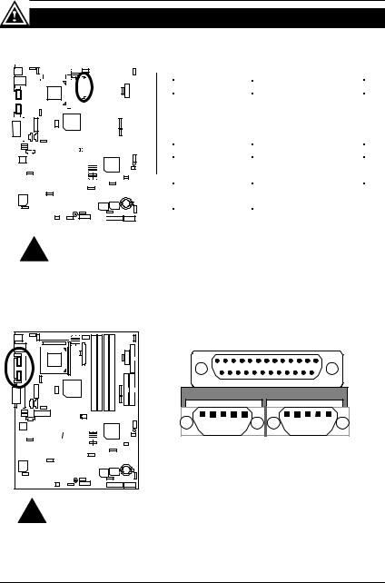
COM A / COM B / LPT Port
LPT Port |
|
|
|
|
|
|
|
|
|
|
|
|
|
|
|
|
|
|
|
|
|
|
|
|
|
|
|
|
|
|
|
|
|
|
|
|
|
|
|
|
|
|
|
|
|
|
|
|
|
|
|
|
|
|
|
|
|
|
|
|
|
|
|
|
|
|
|
|
|
|
|
|
|
|
|
|
|
|
|
|
|
|
|
|
|
|
|
|
|
|
|
|
|
|
|
|
|
|
|
|
|
|
|
|
|
|
|
|
|
|
|
|
|
|
|
|
|
|
|
|
|
|
|
|
|
|
|
|
|
|
|
|
COM A |
COM B |
||||||||||||||||
|
|
|
|
|
|
|
|
|
|
|
|
|
|
|
|
|
|
|
|
|
|
|
|
|
|
|
|
|
|
|
|
||||||||||||||||||
|
|
|
|
|
|
|
|
|
|
|
|
|
|
|
|
|
|
|
|
|
|
|
|
|
|
|
|
|
|
|
|
||||||||||||||||||
|
|
|
|
|
|
|
|
|
|
|
|
|
|
|
|
|
|
|
|
|
|
|
|
|
|
|
|
|
|
|
|
||||||||||||||||||
|
|
|
|
|
|
|
|
|
|
|
|
|
|
|
|
|
|
|
|
|
|
|
|
|
|
|
|
|
|
|
|
||||||||||||||||||
|
|
|
|
|
|
|
|
|
|
|
|
|
|
|
|
|
|
|
|
|
|
|
|
|
|
|
|
|
|
|
|||||||||||||||||||
|
|
|
|
|
|
|
|
|
|
|
|
|
|
|
|
|
|
|
|
|
|
|
|
|
|
|
|
|
|
|
|
|
|
|
|
|
|
|
|
|
|
|
|
|
|
|
|
|
|
|
|
|
|
|
|
|
|
|
|
|
|
|
|
|
|
|
|
|
|
|
|
|
|
|
|
|
|
|
|
|
|
|
|
|
|
|
|
|
|
|
|
|
|
|
|
|
|
|
|
|
|
|
|
|
|
|
|
|
|
|
|
|
|
|
|
|
|
|
|
|
|
|
|
|
|
|
|
|
|
|
|
|
|
|
|
|
|
|
|
|
|
|
|
|
|
|
|
|
|
|
|
|
|
|
|
|
|
|
|
|
|
|
|
|
|
|
|
|
|
|
|
|
|
|
|
|
|
|
|
|
|
|
|
|
|
|
|
|
|
|
|
|
|
|
|
|
|
|
|
|
|
|
|
|
|
|
|
|
|
|
|
|
|
|
|
|
|
|
|
|
|
|
|
|
|
|
|
|
|
|
|
|
|
|
|
|
|
|
|
|
|
|
|
|
|
|
|
|
|
|
|
|
|
|
|
|
|
|
|
|
|
|
|
|
|
|
|
|
|
|
|
|
|
|
|
|
|
|
|
|
|
|
|
|
|
|
|
|
|
|
|
|
|
|
|
|
|
|
|
|
|
|
|
|
|
|
|
|
|
|
|
|
|
|
|
|
|
|
|
|
|
|
|
|
|
|
|
|
|
|
|
|
|
|
|
|
|
|
|
|
|
|
|
|
|
|
|
|
|
|
|
|
|
|
|
|
|
|
|
|
|
|
|
|
|
|
|
|
|
|
|
|
|
|
|
|
|
|
|
|
|
|
|
|
|
|
|
|
|
|
|
|
|
|
|
|
|
|
|
Please note:
This mainboard supports 2 standard COM ports and 1 LPT port. Device like printer can be connected to LPT port ; mouse and modem etc can be connected to COM ports.
17
|
|
|
Connectors |
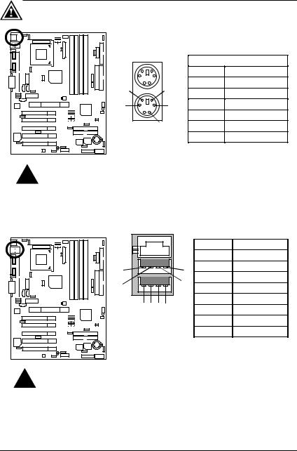
CN7: PS/2 Keyboard & PS/2 Mouse Connector |
|
||
PS/2 Mouse |
PS/2 Mouse/ Keyboard |
||
|
|
||
|
|
Pin No. |
Definition |
6 |
5 |
1 |
Data |
2 |
NC |
||
4 |
3 |
3 |
GND |
|
|
4 |
POWER |
2 |
1 |
5 |
Clock |
PS/2 Keyboard |
6 |
NC |
|
Please note:
This mainboard supports standard PS/2 keyboard and PS/2 mouse interface connector.
CN10: USB & LAN Connector (LAN Connector is optional)
1 |
|
Pin No. |
Definition |
|
|
|
|
||
2 |
|
1 |
USB Power |
|
5 |
8 |
2 |
USB D0- |
|
3 |
USB D0+ |
|||
|
7 |
|||
6 |
4 |
GND |
||
1 2 3 4 |
|
5 |
USB Power |
|
|
6 |
USB D1- |
||
|
|
|||
1 – Green LED |
|
7 |
USB D1+ |
|
(100Mbit/s LED) |
|
8 |
GND |
|
2 – Yellow LED |
|
|
|
|
(LAN Active LED) |
|
|
|
Please note:
Before you connect your device(s) into USB connector(s), please make sure your device(s) has a standard USB interface like, USB keyboard, mouse, scanner, zip, speaker… Also make sure your OS supports USB controller (Win 95 w/ USB supperment, Win98, Windows 2000, Windows ME, Win NT w/ SP 6). If your OS does not support USB controller, please contact OS vander for passible patch or driver upgrade. For more information please contact your OS or device(s) vanders.
18
6RX Series Motherboard
CN9: Front USB Connector (Optional)
|
|
|
|
|
|
|
|
|
|
|
|
|
|
|
|
|
|
|
|
|
|
|
|
|
|
|
|
|
|
|
|
|
|
|
|
|
|
|
|
|
|
|
|
|
|
|
|
|
|
|
|
|
|
|
|
|
|
|
|
|
|
|
|
|
|
|
|
|
|
|
|
|
|
|
|
|
|
|
|
|
|
|
|
|
|
|
|
|
|
|
|
|
|
|
|
|
|
|
|
|
|
|
2 |
10 |
Pin No. |
Definition |
|||||||||||
|
|
|
|
|
|
|
|
|
|
|
|
|
|
|
|
|
|
|
|
|
|
|
|
|
|
|
|
|
|
|
|
|
|
|
|
|
|
|
|
|
|
1 |
POWER |
|||||||||||||||
|
|
|
|
|
|
|
|
|
|
|
|
|
|
|
|
|
|
|
|
|
|
|
|
|
|
|
|
|
|
|
|
|
|
|
|
|
|
|
|
|
|
|
|
|
|
|
|
|
|
|
|
|
|
|
|
|
2 |
GND |
|
|
|
|
|
|
|
|
|
|
|
|
|
|
|
|
|
|
|
|
|
|
|
|
|
|
|
|
|
|
|
|
|
|
|
|
|
|
|
|
|
|
|
|
|
|
|
|
|
|
|
|
|
|
|
|
|
3 |
USB D2- |
|
|
|
|
|
|
|
|
|
|
|
|
|
|
|
|
|
|
|
|
|
|
|
|
|
|
|
|
|
|
|
|
|
|
|
|
|
|
|
|
|
|
|
|
1 |
9 |
|
||||||||||||
|
|
|
|
|
|
|
|
|
|
|
|
|
|
|
|
|
|
|
|
|
|
|
|
|
|
|
|
|
|
|
|
|
|
|
|
|
|
|
|
|
|
|
|
4 |
NC |
|||||||||||||
|
|
|
|
|
|
|
|
|
|
|
|
|
|
|
|
|
|
|
|
|
|
|
|
|
|
|
|
|
|
|
|
|
|
|
|
|
|
|
|
|
|
|
|
|
|
|
|
|
|
|
|
|
|
|
|
|
5 |
USB D2+ |
|
|
|
|
|
|
|
|
|
|
|
|
|
|
|
|
|
|
|
|
|
|
|
|
|
|
|
|
|
|
|
|
|
|
|
|
|
|
|
|
|
|
|
|
|
|
|
|
|
|
|
|
|
|
|
|
|
||
|
|
|
|
|
|
|
|
|
|
|
|
|
|
|
|
|
|
|
|
|
|
|
|
|
|
|
|
|
|
|
|
|
|
|
|
|
|
|
|
|
|
|
|
|
|
|
|
|
|
|
|
|
|
|
|
|
6 |
USB D3+ |
|
|
|
|
|
|
|
|
|
|
|
|
|
|
|
|
|
|
|
|
|
|
|
|
|
|
|
|
|
|
|
|
|
|
|
|
|
|
|
|
|
|
|
|
|
|
|
|
|
|
|
|
|
|
|
|
|
||
|
|
|
|
|
|
|
|
|
|
|
|
|
|
|
|
|
|
|
|
|
|
|
|
|
|
|
|
|
|
|
|
|
|
|
|
|
|
|
|
|
|
|
|
|
|
|
|
|
|
|
|
|
|
|
|
|
||
|
|
|
|
|
|
|
|
|
|
|
|
|
|
|
|
|
|
|
|
|
|
|
|
|
|
|
|
|
|
|
|
|
|
|
|
|
|
|
|
|
|
|
|
|
|
|
|
|
|
|
|
|
|
|
|
|
|
|
|
|
|
|
|
|
|
|
|
|
|
|
|
|
|
|
|
|
|
|
|
|
|
|
|
|
|
|
|
|
|
|
|
|
|
|
|
|
|
|
|
|
|
|
|
|
|
|
|
|
|
|
|
|
|
|
|
7 |
NC |
|
|
|
|
|
|
|
|
|
|
|
|
|
|
|
|
|
|
|
|
|
|
|
|
|
|
|
|
|
|
|
|
|
|
|
|
|
|
|
|
|
|
|
|
|
|
|
|
|
|
|
|
|
|
|
|
|
||
|
|
|
|
|
|
|
|
|
|
|
|
|
|
|
|
|
|
|
|
|
|
|
|
|
|
|
|
|
|
|
|
|
|
|
|
|
|
|
|
|
|
|
|
|
|
|
|
|
|
|
|
|
|
|
|
|
8 |
USB D3- |
|
|
|
|
|
|
|
|
|
|
|
|
|
|
|
|
|
|
|
|
|
|
|
|
|
|
|
|
|
|
|
|
|
|
|
|
|
|
|
|
|
|
|
|
|
|
|
|
|
|
|
|
|
|
|
|
|
9 |
GND |
|
|
|
|
|
|
|
|
|
|
|
|
|
|
|
|
|
|
|
|
|
|
|
|
|
|
|
|
|
|
|
|
|
|
|
|
|
|
|
|
|
|
|
|
|
|
|
|
|
|
|
|
|
|
|
|
|
||
|
|
|
|
|
|
|
|
|
|
|
|
|
|
|
|
|
|
|
|
|
|
|
|
|
|
|
|
|
|
|
|
|
|
|
|
|
|
|
|
|
|
|
|
|
|
|
|
|
|
|
|
|
|
|
|
|
||
|
|
|
|
|
|
|
|
|
|
|
|
|
|
|
|
|
|
|
|
|
|
|
|
|
|
|
|
|
|
|
|
|
|
|
|
|
|
|
|
|
|
|
|
|
|
|
|
|
|
|
|
|
|
|
|
|
||
|
|
|
|
|
|
|
|
|
|
|
|
|
|
|
|
|
|
|
|
|
|
|
|
|
|
|
|
|
|
|
|
|
|
|
|
|
|
|
|
|
|
|
|
|
|
|
|
|
|
|
|
|
|
|
|
|
||
|
|
|
|
|
|
|
|
|
|
|
|
|
|
|
|
|
|
|
|
|
|
|
|
|
|
|
|
|
|
|
|
|
|
|
|
|
|
|
|
|
|
|
|
|
|
|
|
|
|
|
|
|
|
|
|
|
|
|
|
|
|
|
|
|
|
|
|
|
|
|
|
|
|
|
|
|
|
|
|
|
|
|
|
|
|
|
|
|
|
|
|
|
|
|
|
|
|
|
|
|
|
|
|
|
|
|
|
|
|
|
|
|
|
|
|
10 |
POWER |
Please note:
Be careful with the polarity of the front panel USB connector. Check the pin assignment while you connect the front panel USB cable. Please contact your nearest dealer for optional front panel USB cable.
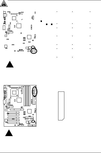
Floppy Port
 RED LINE
Please note:
Remove the smart card reader cable before you plug Floppy B, you cannot use Floppy B and smart card reader simultaneously.
19
Connectors
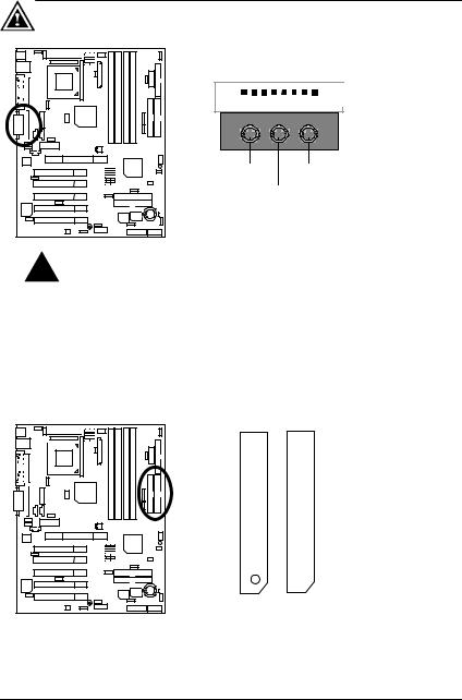
Game & Audio Port


 Game
Game
Port
Line Out 1 |
MIC In |
Line In/Line Out 2
Please note:
Line Out 1: Line Out or SPDIF (The SPDIF output is capable of providing digital audio to external speakers or compressed AC3 data to an external Dolby digital decoder). To enable SPDIF, simply insert SPDIF connector into Line Out1. Line
Out1 will become SPDIF Out automatically. (see page 57 for more information). To enable Four Speaker (for Creative 5880 audio only), simply follow instructions on
page 54 and Line In will become Line Out2 to support second pair of stereo speakers.
IDE1 (Primary), IDE2 (Secondary) Port
 RED LINE
IDE 1 IDE 2
20
6RX Series Motherboard
IDE3/IDE4 (Raid/ATA100) Port (Optional)
IDE 4
 IDE 3
IDE 3
RED LINE
J4: CD Audio Line In
1 |
|
|
|
|
|
|
|
|
|
|
|
|
|
|
|
|
|
|
|
|
|
|
|
|
|
|
|
|
|
|
|
|
|
|
|
|
|
|
|
|
|
|
|
|
|
|
|
|
|
|
|
|
|
|
|
|
|
|
|
|
|
|
|
|
|
|
|
|
|
|
|
|
|
|
|
|
|
|
|
|
|
|
|
|
|
|
|
|
|
|
|
|
|
|
|
|
|
|
|
|
|
|
|
|
|
|
|
|
|
|
|
|
|
|
|
|
|
|
|
|
|
|
|
|
|
|
|
|
|
|
|
|
|
|
|
|
|
|
|
|
|
|
|
|
|
|
|
|
|
|
|
|
|
|
|
|
|
|
|
|
|
|
|
|
|
|
|
|
|
|
|
|
|
|
|
|
|
|
|
|
|
|
|
|
|
|
|
|
|
|
|
|
|
|
|
|
|
|
|
|
|
|
|
|
|
|
|
|
|
|
|
|
|
|
|
|
|
|
|
|
|
|
|
|
|
|
|
|
|
|
|
|
|
|
|
|
|
|
|
|
|
|
|
|
|
|
|
|
|
|
|
|
|
|
|
|
|
|
|
|
|
|
|
|
|
|
|
|
|
|
|
|
|
|
|
|
|
|
|
|
|
|
|
|
|
|
|
|
|
|
|
|
|
|
|
|
|
|
|
|
|
|
|
|
|
|
|
|
|
|
|
|
|
|
|
|
|
|
|
|
|
|
|
|
|
|
|
|
|
|
|
|
|
|
|
|
|
|
|
|
|
|
|
|
|
|
|
|
|
|
|
|
|
|
|
|
|
|
|
|
|
|
|
|
|
|
|
|
|
|
|
|
|
|
|
|
|
|
|
|
|
|
|
|
|
|
|
|
|
|
|
|
|
|
|
|
|
|
|
|
|
|
|
|
|
|
|
|
|
|
|
|
|
|
|
|
|
|
|
|
|
|
|
|
|
|
|
|
|
|
|
|
|
|
|
|
|
|
|
|
|
|
|
|
|
|
|
|
|
|
|
|
|
|
|
|
|
|
|
|
|
|
|
|
|
|
|
|
|
|
|
|
|
|
|
|
|
|
|
|
|
|
|
|
|
|
|
|
|
|
|
|
|
|
|
|
|
|
|
|
|
|
|
|
|
|
|
|
|
|
|
|
|
|
|
|
|
|
|
|
|
|
|
|
|
|
|
|
|
|
|
|
|
|
|
|
|
|
|
|
|
|
|
|
|
|
|
|
|
|
|
|
|
|
|
|
|
|
|
|
|
|
|
|
|
|
|
|
|
|
|
|
Pin No. |
Definition |
||
|
|
|
|
|
|
|
|
|
|
|
|
|
|
|
|
|
|
|
|
|
|
|
|
|
|
|
|
|
|
|
|
|
|
|
|
|
|
|
|
|
|||||||
|
|
|
|
|
|
|
|
|
|
|
|
|
|
|
|
|
|
|
|
|
|
|
|
|
|
|
|
|
|
|
|
|
|
|
|
|
|
|
|
|
|||||||
|
|
|
|
|
|
|
|
|
|
|
|
|
|
|
|
|
|
|
|
|
|
|
|
|
|
|
|
|
|
|
|
|
|
|
|
|
|
|
|
|
|
|
|
|
|
||
|
|
|
|
|
|
|
|
|
|
|
|
|
|
|
|
|
|
|
|
|
|
|
|
|
|
|
|
1 |
|
|
CD-L |
||||||||||||||||
|
|
|
|
|
|
|
|
|
|
|
|
|
|||||||||||||||||||||||||||||||||||
|
|
|
|
|
|
|
|
|
|
|
|
|
|
|
|
|
|
|
|
|
|
|
|
|
|
||||||||||||||||||||||
|
|
|
|
|
|
|
|
|
|
|
|
|
|
|
|
|
|
|
|
|
|
|
|
|
|
|
|
|
|
|
|
|
|
|
|
|
|
|
|
|
2 |
|
|
GND |
|||
|
|
|
|
|
|
|
|
||||||||||||||||||||||||||||||||||||||||
|
|
|
|
|
|
|
|
|
|
|
|
|
|
|
|
|
|
|
|
|
|
|
|
|
|
|
|
|
|
|
|
|
|
|
|
|
|
|
|
|
|
|
|
|
|||
|
|
|
|
|
|
|
|
|
|
|
|
|
|
|
|
|
|
|
|
|
|
|
|
|
|
|
|
|
|
|
|
|
|
|
|
|
|
|
|
3 |
|
|
GND |
||||
|
|
|
|
|
|
|
|
|
|
|
|
|
|
|
|
|
|
|
|
|
|
|
|
|
|
|
|
|
|
|
|
|
|
|
|
|
|
|
|||||||||
|
|
|
|
|
|
|
|
|
|
|
|
|
|
|
|
|
|
|
|
|
|
|
|
|
|
|
|
|
|
|
|
|
|
|
|
|
|
|
|||||||||
|
|
|
|
|
|
|
|
|
|
|
|
|
|
|
|
|
|
|
|
|
|
|
|
|
|
|
|
|
|
|
|
|
|
|
|
|
|
|
|
|
|
|
|
4 |
|
|
CD-R |
|
|
|
|
|
|
|
|
|
|
|
|
|
|
|
|
|
|
|
|
|
|
|
|
|
|
|
|
|
|
|
|
|
|
|
|
|
|
|
|
|
|
|
|
|
|
||
|
|
|
|
|
|
|
|
|
|
|
|
|
|
|
|
|
|
|
|
|
|
|
|
|
|
|
|
|
|
|
|
|
|
|
|
|
|
|
|
|
|
|
|
|
|
|
|
|
|
|
|
|
|
|
|
|
|
|
|
|
|
|
|
|
|
|
|
|
|
|
|
|
|
|
|
|
|
|
|
|
|
|
|
|
|
|
|
|
|
|
|
|
|
|
|
|
|
|
|
|
|
|
|
|
|
|
|
|
|
|
|
|
|
|
|
|
|
|
|
|
|
|
|
|
|
|
|
|
|
|
|
|
|
|
|
|
|
|
|
|
|
|
|
|
|
|
|
|
|
|
|
|
|
|
|
|
|
|
|
|
|
|
|
|
|
|
|
|
|
|
|
|
|
|
|
|
|
|
|
|
|
|
|
|
|
|
|
|
|
|
|
|
|
|
|
|
|
|
|
|
|
|
|
|
|
|
|
|
|
|
|
|
|
|
|
|
|
|
|
|
|
|
|
|
|
|
|
|
|
|
|
|
|
|
|
|
|
|
|
21
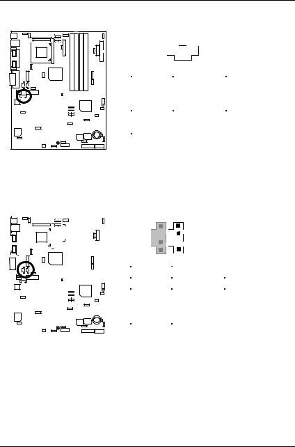
Connectors
J3: AUX_IN (Optional)
1
|
|
|
|
|
|
|
|
|
|
|
|
|
|
|
|
|
|
|
|
|
|
|
|
|
|
|
|
|
|
|
|
|
|
|
|
|
|
|
|
|
|
|
|
|
|
|
|
|
|
|
|
|
|
|
|
|
|
|
|
|
|
|
|
|
|
|
|
|
|
|
|
|
|
|
|
|
|
|
|
|
|
|
|
|
|
|
|
|
|
|
|
|
|
|
|
|
|
|
|
|
|
|
|
|
|
|
|
|
|
|
|
|
|
|
|
|
|
|
|
|
|
|
|
|
|
|
|
|
|
|
|
|
|
|
|
|
|
|
|
|
|
|
|
|
|
|
|
|
|
|
|
|
|
|
|
|
|
|
|
|
|
|
|
|
|
|
|
|
|
|
|
|
|
|
|
|
|
|
|
|
|
|
|
|
|
|
|
|
|
|
|
|
|
|
|
|
|
|
|
|
|
|
|
|
|
|
|
|
|
|
|
|
|
|
|
|
|
|
|
|
|
|
|
|
|
|
|
|
|
|
|
|
|
|
|
|
|
|
|
|
|
|
|
|
|
|
|
|
|
|
|
|
|
|
|
|
|
|
|
|
|
|
|
|
|
|
|
|
|
|
|
|
|
|
|
|
|
|
|
|
|
|
|
|
|
|
|
|
|
|
|
|
|
|
|
|
|
|
|
|
|
|
|
|
|
|
|
|
|
|
|
|
|
|
|
|
|
|
|
|
|
|
|
|
|
|
|
|
|
|
|
|
|
|
|
|
|
|
|
|
|
|
|
|
|
|
|
|
|
|
|
|
|
|
|
|
|
|
|
|
|
|
|
|
|
|
|
|
|
|
|
|
|
|
|
|
|
|
|
|
|
|
|
|
|
|
|
|
|
|
|
|
|
|
|
|
|
|
|
|
|
|
|
|
|
|
|
|
|
|
|
|
|
|
|
|
|
|
|
|
|
|
|
|
|
|
|
|
|
|
|
|
|
|
|
|
|
|
|
|
|
|
|
|
|
|
|
|
|
|
|
|
|
|
|
|
|
|
|
|
|
|
|
|
|
|
|
|
|
|
|
|
|
|
|
|
|
|
|
|
|
|
|
|
|
|
|
|
|
|
|
|
|
|
|
|
|
|
|
|
|
|
|
|
|
|
|
|
|
|
|
|
|
|
|
|
|
|
|
|
|
|
|
|
|
|
|
|
|
|
|
|
|
|
|
|
|
|
|
|
|
|
|
|
|
|
|
|
|
|
|
|
|
|
|
|
|
|
|
|
|
|
|
|
|
|
|
|
|
|
|
|
|
|
|
|
|
|
|
|
|
|
|
|
|
|
|
|
|
|
|
|
|
|
|
|
|
|
|
|
|
|
Pin No. |
|
Definition |
||||||
|
|
|
|
|
|
|
|
|
|
|
|
|
|
|
|
|
|
|
|
|
|
|
|
|
|
|
|
|
|
|
|
|
|
|
|
|
|
|
||||||||||||
|
|
|
|
|
|
|
|
|
|
|
|
|
|
|
|
|
|
|
|
|
|
|
|
|
|
|
|
|
|
|
|
|
|
|
|
|
|
|
1 |
|
|
|
|
AUX-L |
||||||
|
|
|
|
|
|
|
|
|
|
|
|
|
|
|
|
|
|
|
|
|
|
|
|
|
|
|
|
|
|
|
|
|
|
|
|
|
|
|
||||||||||||
|
|
|
|
|
|
|
|
|
|
|
|
|
|
|
|
|
|
|
|
|
|
|
|
|
|
|
|
|
|
|
|
|
|
|
|
|
|
|||||||||||||
|
|
|
|
|
|
|
|
|
|
|
|
|
|
|
|
|
|
|
|
|
|
|
|
|
|
|
|
|
|
|
|
|
|
|
|
|
|
|||||||||||||
|
|
|
|
|
|
|
|
|
|
|
|
|
|
|
|
|
|
|
|
|
|
|
|
|
|
|
|
|
|
|
|
|
|
|
|
|
|
|||||||||||||
|
|
|
|
|
|
|
|
|
|
|
|
|||||||||||||||||||||||||||||||||||||||
|
|
|
|
|
|
|
|
|
|
|
|
|
|
|
|
|
|
|
|
|
|
|
|
|
|
|
|
|
|
|
|
|
|
|
|
|
|
|
2 |
|
|
|
|
GND |
||||||
|
|
|
|
|
|
|
|
|
|
|
|
|
|
|
|
|
|
|
|
|
|
|
|
|
|
|
|
|
|
|
|
|
|
|
|
|
||||||||||||||
|
|
|
|
|
|
|
|
|
|
|
|
|
|
|
|
|
|
|
|
|
|
|
|
|
|
|
|
|
|
|
|
|
|
|
|
|
|
|||||||||||||
|
|
|
|
|
|
|
||||||||||||||||||||||||||||||||||||||||||||
|
|
|
|
|
|
|
|
|
|
|
|
|
|
|
|
|
|
|
|
|
|
|
|
|
|
|
|
|
|
|
|
|
3 |
|
|
|
|
GND |
||||||||||||
|
|
|
|
|
|
|
|
|
|
|
|
|
|
|
|
|
|
|
|
|
|
|
|
|
|
|
|
|
|
|
|
|
|
|
|
|
|
|
|
|
|
|
|
|
|
|||||
|
|
|
|
|
|
|
|
|
|
|
|
|
|
|
|
|
|
|
|
|
|
|
|
|
|
|
|
|
|
|
|
|
|
|
|
|
|
|
|
|
|
|
|
|
|
|
|
|
|
|
|
|
|
|
|
|
|
|
|
|
|
|
|
|
|
|
|
|
|
|
|
|
|
|
|
|
|
|
|
|
|
|
|
|
|
|
|
4 |
|
|
|
AUX-R |
|||||||||
|
|
|
|
|
|
|
|
|
|
|
|
|
|
|
|
|
|
|
|
|
|
|
|
|
|
|
|
|
|
|
|
|
|
|
|
|
|
|
|
|
|
|
|
|
|
|
|
|
|
|
|
|
|
|
|
|
|
|
|
|
|
|
|
|
|
|
|
|
|
|
|
|
|
|
|
|
|
|
|
|
|
|
|
|
|
|
|
|
|
|
|
|
|
|
|
|
|
|
|
|
|
|
|
|
|
|
|
|
|
|
|
|
|
|
|
|
|
|
|
|
|
|
|
|
|
|
|
|
|
|
|
|
|
|
|
|
|
|
|
|
|
|
|
|
|
|
|
|
|
|
|
|
|
|
|
|
|
|
|
|
|
|
|
|
|
|
|
|
|
|
|
|
|
|
|
|
|
|
|
|
|
|
|
|
|
|
|
|
|
|
|
|
|
|
|
|
|
|
|
|
|
|
|
|
|
|
|
|
|
|
|
|
|
|
|
|
|
|
|
|
|
|
|
|
|
|
|
|
|
|
|
|
|
|
|
|
|
|
|
|
|
|
|
|
|
|
|
|
|
|
|
|
|
|
|
|
|
|
|
|
|
|
|
|
|
|
|
|
|
|
|
|
|
|
|
|
|
|
|
|
|
|
|
|
|
|
|
|
|
|
|
|
|
|
|
|
|
|
|
|
|
|
|
|
|
J5: TEL (The connector is for internal modem card with voice connector) (Optional)
|
|
|
|
|
|
|
|
|
|
|
|
|
|
|
|
|
|
|
|
|
|
|
|
|
|
|
|
|
|
|
|
|
|
|
|
|
|
|
|
|
|
|
|
|
|
1 |
||
|
|
|
|
|
|
|
|
|
|
|
|
|
|
|
|
|
|
|
|
|
|
|
|
|
|
|
|
|
|
|
|
|
|
|
|
|
|
|
|
|
|
|
|
|
|
|||
|
|
|
|
|
|
|
|
|
|
|
|
|
|
|
|
|
|
|
|
|
|
|
|
|
|
|
|
|
|
|
|
|
|
|
|
|
|
|
|
|
|
|
|
|
|
|
|
|
|
|
|
|
|
|
|
|
|
|
|
|
|
|
|
|
|
|
|
|
|
|
|
|
|
|
|
|
|
|
|
|
|
|
|
|
|
|
|
|
|
|
|
|
|
|
|
|
|
|
|
|
|
|
|
|
|
|
|
|
|
|
|
|
|
|
|
|
|
|
|
|
|
|
|
|
|
|
|
|
|
|
|
|
|
|
|
|
|
|
|
|
Pin No. |
|
Definition |
|||
|
|
|
|
|
|
|
|
|
|
|
|
|
|
|
|
|
|
|
|
|
|
|
|
|
|
|
|
|
|
|
|
|
|
|
|
|
|
|
|
|||||||||
|
|
|
|
|
|
|
|
|
|
|
|
|
|
|
|
|
|
|
|
|
|
|
|
|
|
|
|
|
|
|
|
|
|
|
|
|
|
|
|
|
|
|
|
|
|
|
|
|
|
|
|
|
|
|
|
|
|
|
|
|
|
|
|
|
|
|
|
|
|
|
|
|
|
|
|
|
|
|
1 |
|
|
|
Signal-In |
||||||||||||||
|
|
|
|
|
|
|
|
|
|
|
|
|
||||||||||||||||||||||||||||||||||||
|
|
|
|
|
|
|
|
|
|
|
|
|
|
|
|
|
|
|
|
|
|
|
|
|
|
|
||||||||||||||||||||||
|
|
|
|
|
|
|
|
|
|
|
|
|
|
|
|
|
|
|
|
|
|
|
|
|
|
|
|
|
|
|
|
|
|
|
|
|
|
|
|
|
|
|
|
|
|
|
||
|
|
|
|
|
|
|
|
|
|
|
|
|
|
|
|
|
|
|
|
|
|
|
|
|
|
|
|
|
|
|
|
|
|
|
|
|
|
|
|
|
2 |
|
|
|
|
GND |
||
|
|
|
|
|
|
|
|
|
|
|
|
|
|
|
|
|
|
|
|
|
|
|
|
|
|
|
|
|
|
|
|
|
|
|
|
|
|
|
|
|
|
|
|
|
|
|
||
|
|
|
|
|
|
|
|
|
|
|
|
|
|
|
|
|
|
|
|
|
|
|
|
|
|
|
|
|
|
|
|
|
|
|
|
|
|
|
|
|
|
|
|
|
|
|
|
|
|
|
|
|
|
|
|
|
|
|
|
|
|
|
|
|
|
|
|
|
|
|
|
|
|
|
|
|
|
|
|
|
|
|
|
|
|
|
|
|
3 |
|
|
|
|
GND |
|||
|
|
|
|
|
|
|
|
|
|
|
|
|
|
|
|
|
|
|
|
|
|
|
|
|
|
|
|
|
|
|
|
|
|
|
|
|
|
|||||||||||
|
|
|
|
|
|
|
|
|
|
|
|
|
|
|
|
|
|
|
|
|
|
|
|
|
|
|
|
|
|
|
|
|
|
|
|
|
|
|
|
|
|
|
4 |
|
|
Signal-Out |
||
|
|
|
|
|
|
|
|
|
|
|
|
|
|
|
|
|
|
|
|
|
|
|
|
|
|
|
|
|
|
|
|
|
|
|
|
|
|
|
|
|
|
|
|
|
||||
|
|
|
|
|
|
|
|
|
|
|
|
|
|
|
|
|
|
|
|
|
|
|
|
|
|
|
|
|
|
|
|
|
|
|
|
|
|
|
|
|
|
|
|
|
|
|
|
|
|
|
|
|
|
|
|
|
|
|
|
|
|
|
|
|
|
|
|
|
|
|
|
|
|
|
|
|
|
|
|
|
|
|
|
|
|
|
|
|
|
|
|
|
|
|
|
|
|
|
|
|
|
|
|
|
|
|
|
|
|
|
|
|
|
|
|
|
|
|
|
|
|
|
|
|
|
|
|
|
|
|
|
|
|
|
|
|
|
|
|
|
|
|
|
|
|
|
|
|
|
|
|
|
|
|
|
|
|
|
|
|
|
|
|
|
|
|
|
|
|
|
|
|
|
|
|
|
|
|
|
|
|
|
|
|
|
|
|
|
|
|
|
|
|
|
|
|
|
|
|
|
|
|
|
|
|
|
|
|
|
|
|
|
|
|
|
|
|
|
|
|
|
|
|
|
|
|
|
|
|
|
|
|
|
|
|
|
|
|
|
|
|
|
|
|
22
 Loading...