

GIGABYTE GA-6PXSV1 Owner's Manual

GA-6PXSV1
LGA 2011 socket motherboard for Intel® E5-1600 series processors
User's Manual
Rev. 1001

Copyright
© 2012 GIGA-BYTE TECHNOLOGY CO., LTD. All rights reserved.
The trademarks mentioned in this manual are legally registered to their respective owners.
Disclaimer
Information in this manual is protected by copyright laws and is the property of GIGABYTE.
Changes to the specifications and features in this manual may be made by GIGABYTE
without prior notice. No part of this manual may be reproduced, copied, translated, transmitted, or
published in any form or by any means without GIGABYTE's prior written permission.
Documentation Classications
In order to assist in the use of this product, GIGABYTE provides the following types of documentations:
For quick set-up of the product, read the Quick Installation Guide included with the product.
For detailed product information, carefully read the User's Manual.
For product-related information, check on our website at:
http://www.gigabyte.com

Table of Contents
Box Contents ...................................................................................................................4
GA-6PXSV1 Motherboard Layout ...................................................................................5
Chapter 1 Hardware Installation .....................................................................................8
1-1 Installation Precautions .................................................................................... 8
1-2 ProductSpecications ...................................................................................... 9
1-3 Installing the CPU and CPU Cooler ............................................................... 11
1-3-1 Installing the CPU ...................................................................................................11
1-3-2 Installing the CPU Cooler .......................................................................................13
1-4 Installing the Memory ..................................................................................... 14
1-4-1 FourChannelMemoryConguration .....................................................................14
1-4-2 Installing a Memory ...............................................................................................15
1-4-3 DIMM Population Table .........................................................................................15
1-5 Back Panel Connectors .................................................................................. 16
1-6 Internal Connectors ........................................................................................ 18
Chapter 2 BIOS Setup ..................................................................................................32
2-1 The Main Menu .............................................................................................. 34
2-2 Advanced Menu ............................................................................................. 36
2-2-1 Trusted Computing .................................................................................................37
2-2-2 CPUConguration ..................................................................................................38
2-2-2-1 CPUPowerManagementConguration ................................................................41
2-2-3 SATAConguration.................................................................................................42
2-2-4 USBConguration ..................................................................................................43
2-2-5 SuperIOConguration ...........................................................................................44
2-2-6 H/W Monitor ............................................................................................................46
2-2-7 Serial Port Console Redirection .............................................................................47
2-3 Chipset Menu ................................................................................................. 49
2-3-1 NorthBridgeConguration .....................................................................................50
2-3-1-1 IOHConguration ...................................................................................................51
2-3-1-2 DIMM Information ...................................................................................................54
2-3-2 SouthBridgeConguration ....................................................................................55
2-3-3 ME Subsystem .......................................................................................................57
2-4 Security Menu ................................................................................................ 58
2-5 Boot Option Menu .......................................................................................... 59
2-6 Boot Manager ................................................................................................. 60
2-7 Exit Menu ....................................................................................................... 61
- 3 -
Box Contents
GA-6PXSV1 motherboard
User's Manual
Driver CD
Two SATA cables
I/O Shield
• The box contents above are for reference only and the actual items shall depend on the product package you obtain.
The box contents are subject to change without notice.
• The motherboard image is for reference only.
- 4 -
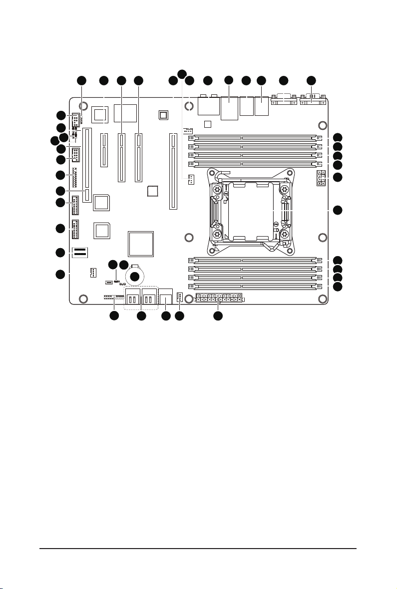
GA-6PXSV1 Motherboard Layout
37 38 39 40 414243
36
35
34
33
32
31
30
29
28
27
26
23
25
22
21
24
1
17181920
3 4 5 6
2
7
8
9
10
11
12
13
14
15
16
- 5 -

Item Code Description
1 AUDIO1 Audio jacks
2 USB_LAN1 LAN connector and USB connectors
3 USB_1394 1394 port and USB connectors
4 R_USB1 USB connectors
5 COM2 Serial port
6 COM1 Serial port
7 DDR3_P0_A0 DIMM slot (channel A-0)
8 DDR3_P0_A1 DIMM slot (channel A-1)
9 DDR3_P0_B0 DIMM slot (channel B-0 )
10 DDR3_P0_B1 DIMM slot (channel B-1 )
11 P2_CPU 8 pin power connector
12 CPU0 Intel LGA 2011 socket
13 DDR3_P0_D1 DIMM slot (channel D-1 )
14 DDR3_P0_D0 DIMM slot (channel D-0 )
15 DDR3_P0_C1 DIMM slot (channel C-1 )
16 DDR3_P0_C0 DIMM slot (channel C-0 )
17 P1 24 pin power connector
18 SYS_FAN2 System fan cable connectors
19 SATA01 SATA 6Gb/s connectors
20 SATA2345 SATA 3Gb/s connectors
21 BAT1 Battery socket
22 PWR_LED1 Power LED header
23 CLR_CMOS1 Clear CMOS jumper
24 F_PANEL1 Front panel connector
25 SYS_FAN3 System fan cable connectors
26 SAS0_3 Mini SAS connector
27 F_USB3_1 Front USB 3.0 connector
28 F_USB3_2 Front USB 3.0 connector
29 PCI PCI slot (32bit/33MHz)
30 TPM TPM module
31 F_1394 IEEE 1394 connector
32 BIOS_WP BIOS write protect jumper
33 SSB_ME1 ME recovery jumper
34 BIOS_RVCR1 BIOS recovery jumper
35 PASSWORD1 Clear password jumper
36 FAUDIO_ACZ Front Audio connector
37 SPDIF_JP1 SPDIF header
38 PCIE4 PCI-E slot 4 (x4 slot)
39 PCIE3 PCI-E slot 3 (x8 slot)
40 PCIE2 PCI-E slot 2 (x16 slot/x8 signal)
41 PCIE1 PCI-E slot 1 (x16 slot)
- 6 -

42 CPU_FAN1 CPU fan cable connector
43 SYS_FAN1 System fan cable connector
- 7 -

Chapter 1 Hardware Installation
1-1 Installation Precautions
The motherboard contains numerous delicate electronic circuits and components which can
become damaged as a result of electrostatic discharge (ESD). Prior to installation, carefully read
the user's manual and follow these procedures:
• Prior to installation, do not remove or break motherboard S/N (Serial Number) sticker or
warranty sticker provided by your dealer. These stickers are required for warranty validation.
• Always remove the AC power by unplugging the power cord from the power outlet before
installing or removing the motherboard or other hardware components.
• When connecting hardware components to the internal connectors on the motherboard,
make sure they are connected tightly and securely.
• When handling the motherboard, avoid touching any metal leads or connectors.
• It is best to wear an electrostatic discharge (ESD) wrist strap when handling electronic com-
ponents such as a motherboard, CPU or memory. If you do not have an ESD wrist strap,
keep your hands dry and rst touch a metal object to eliminate static electricity.
• Prior to installing the motherboard, please have it on top of an antistatic pad or within an
electrostatic shielding container.
• Before unplugging the power supply cable from the motherboard, make sure the power sup-
ply has been turned off.
• Before turning on the power, make sure the power supply voltage has been set according to
the local voltage standard.
• Before using the product, please verify that all cables and power connectors of your hard-
ware components are connected.
• To prevent damage to the motherboard, do not allow screws to come in contact with the
motherboard circuit or its components.
• Make sure there are no leftover screws or metal components placed on the motherboard or
within the computer casing.
• Do not place the computer system on an uneven surface
• Do not place the computer system in a high-temperature environment.
• Turning on the computer power during the installation process can lead to damage to sys-
tem components as well as physical harm to the user.
• If you are uncertain about any installation steps or have a problem related to the use of the
product, please consult a certied computer technician.
.
Hardware Installation - 8 -
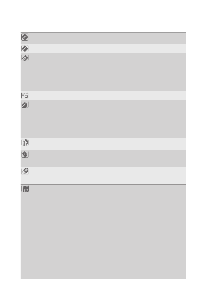
1-2 ProductSpecications
CPU Support for Intel® Xeon® E5 series processors in the LGA2011 package
L3 cache varies with CPU
Chipset Intel® BD82C604 (X79) PCH
Memory 8 x 1.5V DDR3 DIMM sockets supporting up to 64 GB (UDIMM) and
256GB (RDIMM) of system memory
* Due to Windows 32-bit operating system limitation, when more than 4 GB of physical
LAN 1 x Intel® 82579LM supports 10/100/1000 Mbps
memory is installed, the actual memory size displayed will be less than 4 GB.
Four channel memory architecture
Support for DDR3 1600/1333/1066 MHz memory modules
Support for ECC memory modules
Expansion Slots 1 x PCI Express x16 slot, running at x16 (Gen3/PCIE1)
Onboard Audio REALTEK ACL892 HD
Storage Interface 2 x SATA 3Gb/s connectors (SATA0/1)
USB 6 x USB 2.0/1.1 ports
Internal
Connectors
* For optimum performance, if only one PCI Express graphics card is to be installed,
be sure to install it in the PCIEX16 slot.
1 x PCI Express x16 slot, running at x8 (Gen3/PCIE2)
1 x PCI Express x8 slot, running at x8 (Gen3/PCIE3)
1 x PCI Express x4 slot, running at x4 (Gen2/PCIE4)
1 x PCI slot 32-Bit/33MHz
4 x SATA 3Gb/s connectors (SATA2/3/4/5)
1 x SAS 3Gb/s connectors (SAS0_3)
Up to 4 USB 3.0 ports (4 via the USB brackets connected to the internal USB
headers)
1 x 24-pin ATX main power connector
1 x 8-pin ATX 12V power connector
4 x SATA 3Gb/s connectors
2 x SATA 6Gb/s connectors
1 x SAS 3Gb/s connector
1 x CPU fan header
3 x System fan header
1 x front panel header
2 x USB 3.0 headers
1 x TPM header
1 x Front 1394 header
1 x Front audio header
1 x Power LED header
- 9 - Hardware Installation
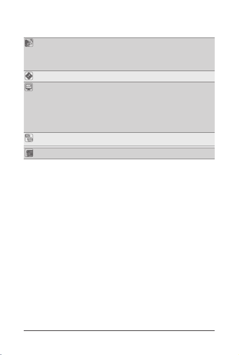
Back Panel
Connectors
6 x USB 2.0/1.1 ports
1 x RJ-45 port
1 x IEEE 1394 port
6 x Audio ports (4 x Line-out/ 1 x Line-in/ 1 x MIC)
2 x COM ports
I/O Controller iTE IT8728 chip
Hardware
Monitor
System voltage detection
CPU/System temperature detection
CPU/System/Power fan speed detection
CPU overheating warning
CPU/System/Power fan fail warning
CPU/System fan speed control
* Whether the CPU/system fan speed control function is supported will depend on
the CPU/system cooler you install.
BIOS 1 x 64 Mbit ash
AMI BIOS
Form Factor ATX Form Factor; 12 inch x 9.6 inch
* GIGA BYTE reserves the right to make any changes to the product specications and product-related information
without prior notice.
Hardware Installation - 10 -
1-3 Installing the CPU and CPU Cooler
Read the following guidelines before you begin to install the CPU:
• Make sure that the motherboard supports the CPU.
(Go to GIGABYTE's website for the latest CPU support list.)
• Always turn off the computer and unplug the power cord from the power outlet before installing
the CPU to prevent hardware damage.
• Locate the pin one of the CPU. The CPU cannot be inserted if oriented incorrectly. (Or you may
locate the notches on both sides of the CPU and alignment keys on the CPU socket.)
• Apply an even and thin layer of thermal grease on the surface of the CPU.
• Do not turn on the computer if the CPU cooler is not installed, otherwise overheating and dam-
age of the CPU may occur.
• Set the CPU host frequency in accordance with the CPU specications. It is not recommended
that the system bus frequency be set beyond hardware specications since it does not meet the
standard requirements for the peripherals. If you wish to set the frequency beyond the standard
specications, please do so according to your hardware specications including the CPU, graphics card, memory, hard drive, etc.
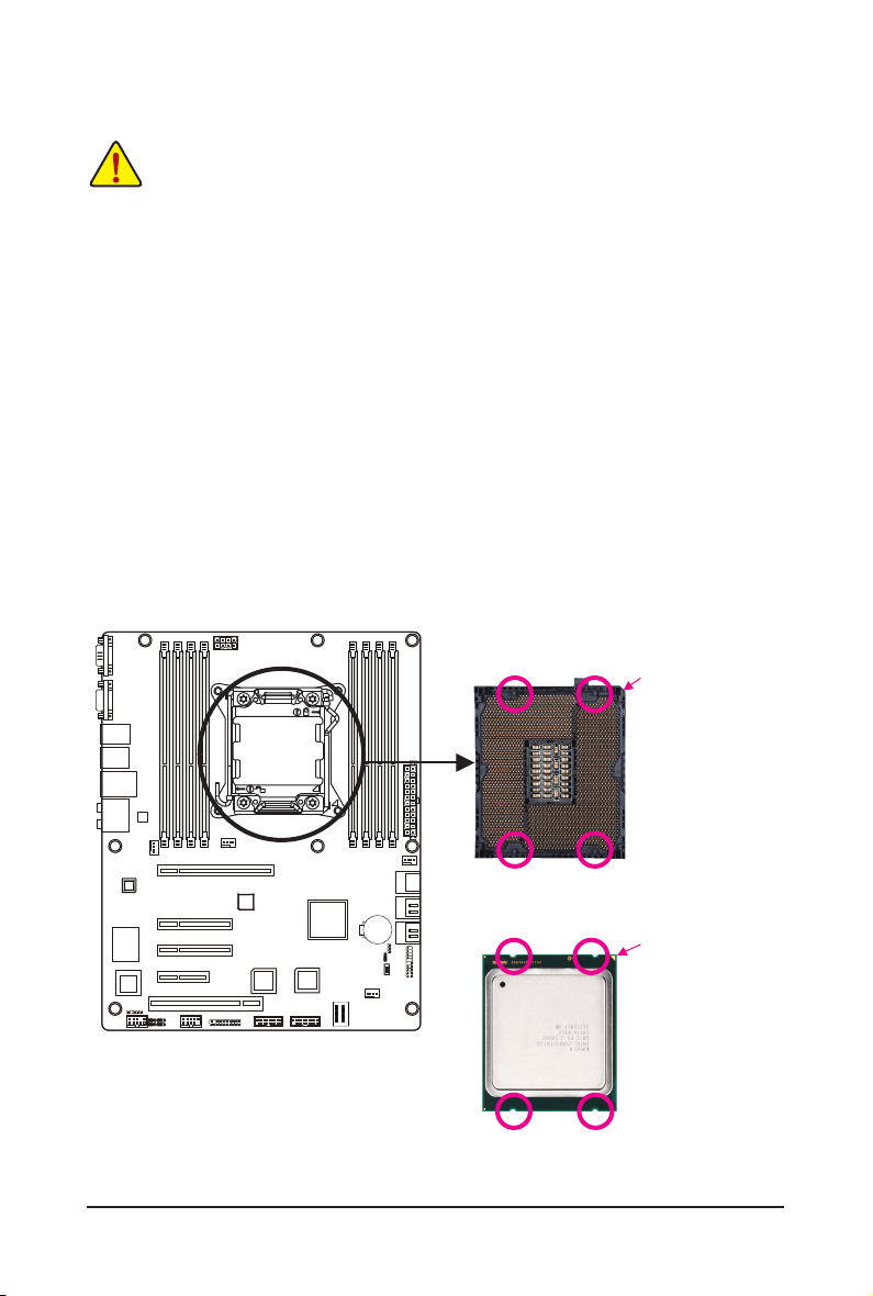
1-3-1 Installing the CPU
A. Locate the alignment keys on the motherboard CPU socket and the notches on the CPU.
LGA2011 CPU
Notch
Notch
Alignment Key
Alignment Key
Notch
Notch
Pin One Corner of the CPU
Socket
Triangle Pin One Marking on
the CPU
Alignment Key
Alignment Key
- 11 - Hardware Installation
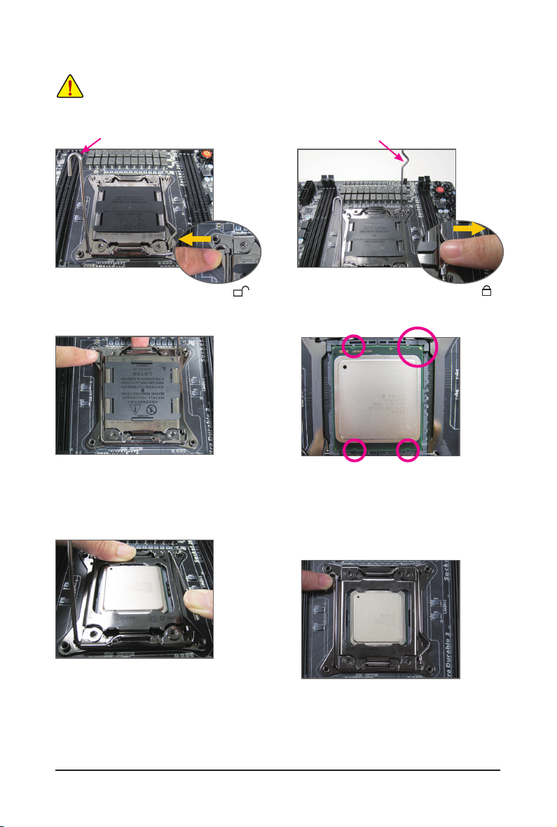
B. Follow the steps below to correctly install the CPU into the motherboard CPU socket.
• Before installing the CPU, make sure to turn off the computer and unplug the power cord
from the power outlet to prevent damage to the CPU.
• To protect the socket contacts, do not remove the protective plastic cover unless the CPU is
inserted into the CPU socket. Save the cover properly and replace it if the CPU is removed.
Lever A
Lever B
Step 1:
Push the lever closest to the "unlock" marking "
"
(below referred as lever A) down and away from
the socket to release it.
Step 3:
Gently press lever A to allow the load plate
to rise. Open the load plate. (Note: DO NOT
touch the socket contacts after the load plate is
opened.)
Step 5:
Once the CPU is properly inserted, carefully replace
the load plate. Then secure lever B under its retention tab. The protective plastic cover may pop off
from the load plate during the process of engaging
the lever. Remove the cover. Save the cover properly
and always replace it when the CPU is not installed.
Hardware Installation - 12 -
Step 2:
Push the lever closest to the "lock" marking "
"
(below referred as lever B) down and away from
the socket. Then lift the lever.
Step 4:
Hold the CPU with your thumb and index fingers.
Align the CPU pin one marking (triangle) with the
pin one corner of the CPU socket (or align the CPU
notches with the socket alignment keys) and carefully insert the CPU into the socket vertically.
Step 6:
Finally, secure lever A under its retention tab to
complete the installation of the CPU.
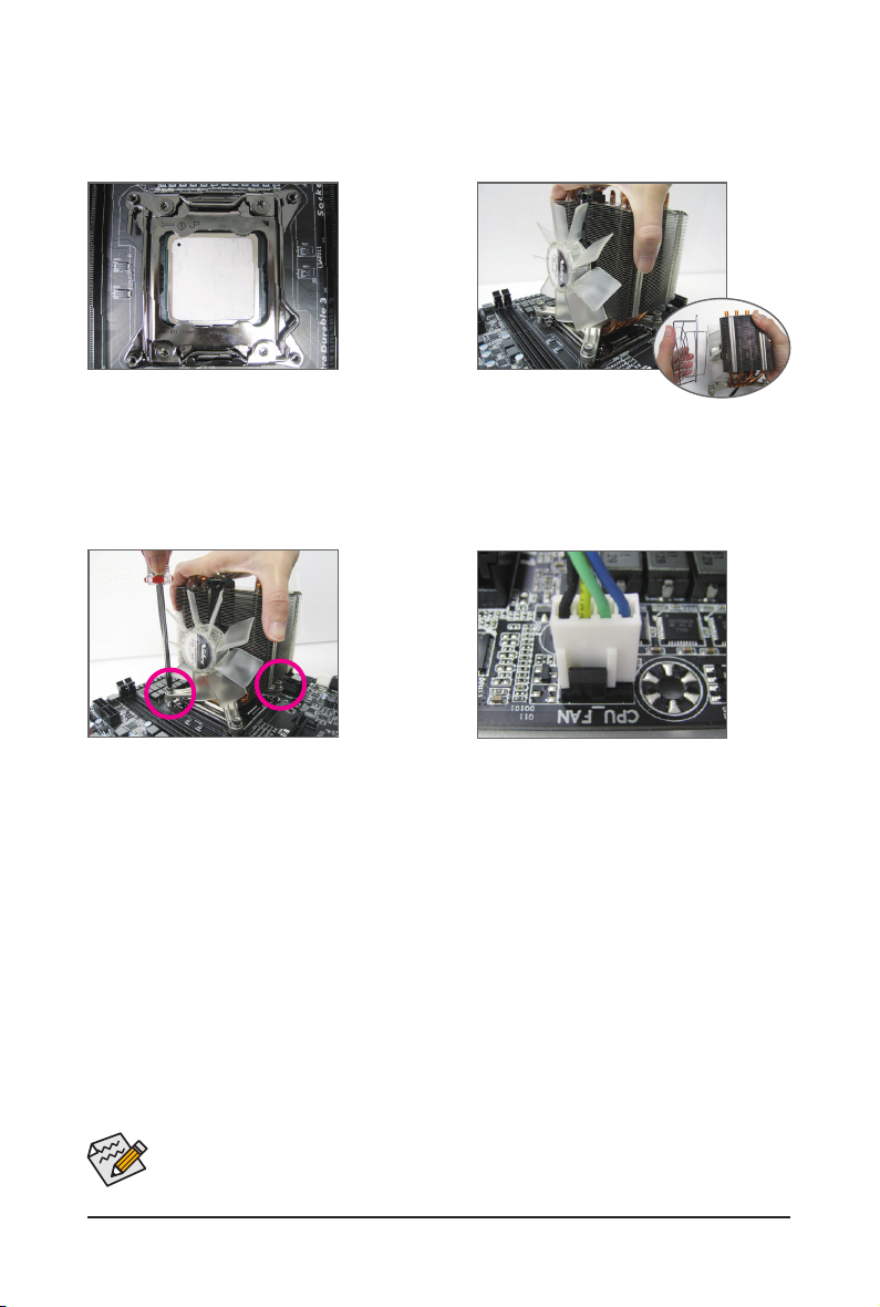
1-3-2 Installing the CPU Cooler
Refer to the steps below to correctly install the CPU cooler on the motherboard. (Actual installation process
may differ depending the CPU cooler to be used. Refer to the user's manual for your CPU cooler.)
Step 1:
Apply an even and thin layer of thermal grease
on the surface of the installed CPU.
Step 3:
Use one hand to hold the cooler and the other to
tighten the screws in a diagonal sequence with
a screw driver. Begin tightening a screw with a
few turns and repeat with the screw diagonally
opposite the one you just tightened. Then do the
same to the other pair. Next, fully tighten the four
screws.
Step 2:
Place the cooler atop the CPU, aligning the four
mounting screws with the mounting holes on
the ILM. (If your cooler has a fan grill which may
cause interference when you tighten the screws,
remove it rst and replace it after tightening the
Step 4:
Finally, attach the power connector of the CPU
cooler to the CPU fan header (CPU_FAN) on the
motherboard.
Please pay more attention when removing the CPU cooler because the thermal grease/tape between the CPU cooler and CPU may adhere to the CPU. Inadequately removing the CPU cooler
may damage the CPU.
- 13 - Hardware Installation
1-4 Installing the Memory
Read the following guidelines before you begin to install the memory:
• Make sure that the motherboard supports the memory. It is recommended that memory of the
same capacity, brand, speed, and chips be used.
(
Go to GIGABYTE's website for the latest supported memory speeds and memory modules.
• Always turn off the computer and unplug the power cord from the power outlet before installing
the memory to prevent hardware damage.
• Memory modules have a foolproof design. A memory module can be installed in only one direction. If you are unable to insert the memory, switch the direction.
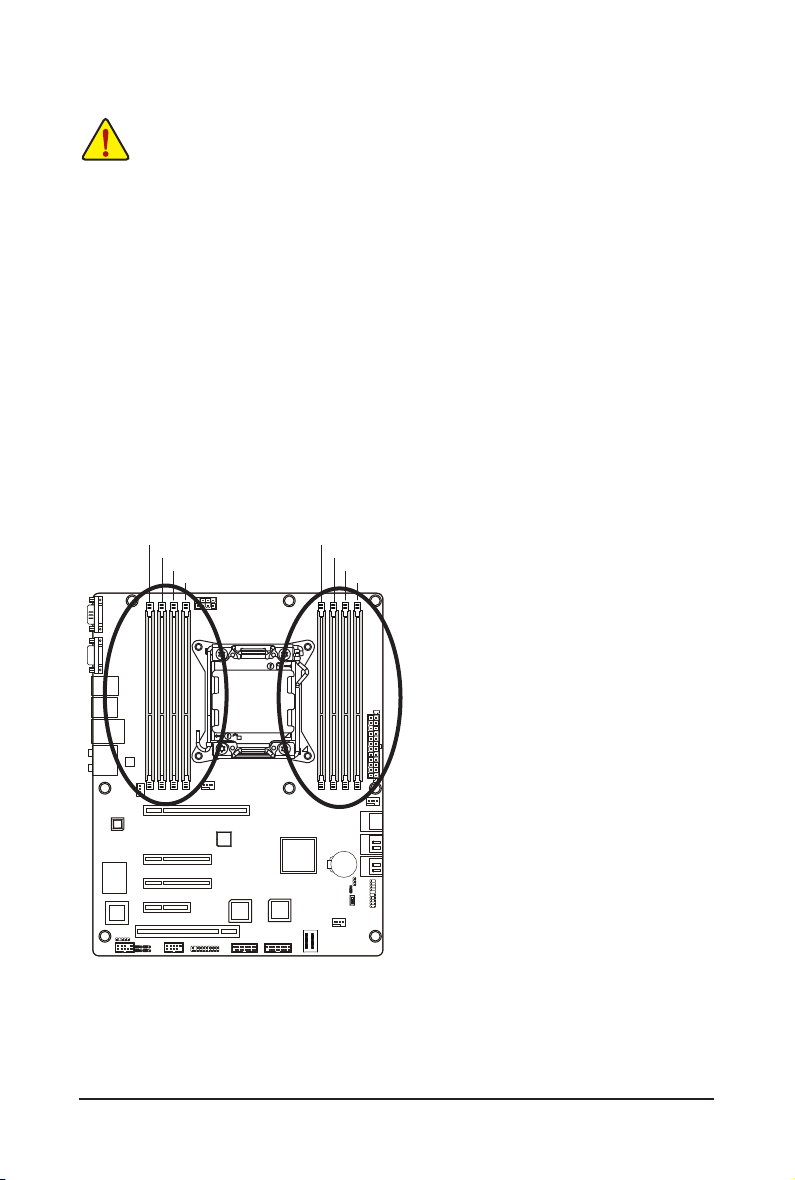
1-4-1 FourChannelMemoryConguration
This motherboard provides four DDR3 memory sockets and supports Four Channel Technology. After the
memory is installed, the BIOS will automatically detect the specications and capacity of the memory. Enabling Four Channel memory mode will double the original memory bandwidth.
The eight DDR3 memory sockets are divided into four channels and each channel has two memory sockets
as following:
Channel A: DDR3_P0_A0, DDR3_P0_A1
Channel B: DDR3_P0_B0, DDR3_P0_B1
Channel C: DDR3_P0_C0, DDR3_P0_C1
Channel D: DDR3_P0_D0, DDR3_P0_D1
DDR3_P0_A0
DDR3_P0_A1
DDR3_P0_B0
DDR3_P0_B1
DDR3_P0_D1
DDR3_P0_D0
DDR3_P0_C1
DDR3_P0_C0
)
Due to CPU limitations, read the following guidelines before installing the memory in Four Channel mode.
1. Four Channel mode cannot be enabled if only one DDR3 memory module is installed.
2. When enabling Four Channel mode with two or four memory modules, it is recommended that
memory of the same capacity, brand, speed, and chips be used for optimum performance.
Hardware Installation - 14 -
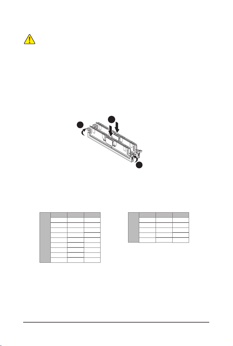
1-4-2 Installing a Memory
Before installing a memory module, make sure to turn off the computer and unplug the power
cord from the power outlet to prevent damage to the memory module.
Be sure to install DDR3 DIMMs on this motherboard.
Installation Step:
Step 1. Insert the DIMM memory module vertically into the DIMM slot, and push it down.
Step 2. Close the plastic clip at both edges of the DIMM slots to lock the DIMM module.
Note: For dual-channel and four-channel operation, DIMMs must be installed in matched pairs.
Step 3. Reverse the installation steps when you wish to remove the DIMM module.
2
1-4-3 DIMM Population Table
1N or 2N
R-DIMM
1N
1N
1N
1N
1N
1N
1N
1N
1N
DIMM1 DIMM0
Empty
Empty
Empty
Single-Rank
Single-Rank
Dual-Rank
Single-Rank
Dual-Rank
Quad-Rank
Single-Rank
Dual-Rank
Quad-Rank
Single-Rank
Dual-Rank
Dual-Rank
Quad-Rank
Quad-Rank
Quad-Rank
1
2
1N
1N
2N
Single-Rank
2N
2N
DIMM1 DIMM0
Empty
Single-Rank
Empty
Dual-Rank
Single-Rank Single-Rank
Dual-Rank
Dual-Rank
Dual-Rank
1N or 2N
U-DIMM
- 15 - Hardware Installation
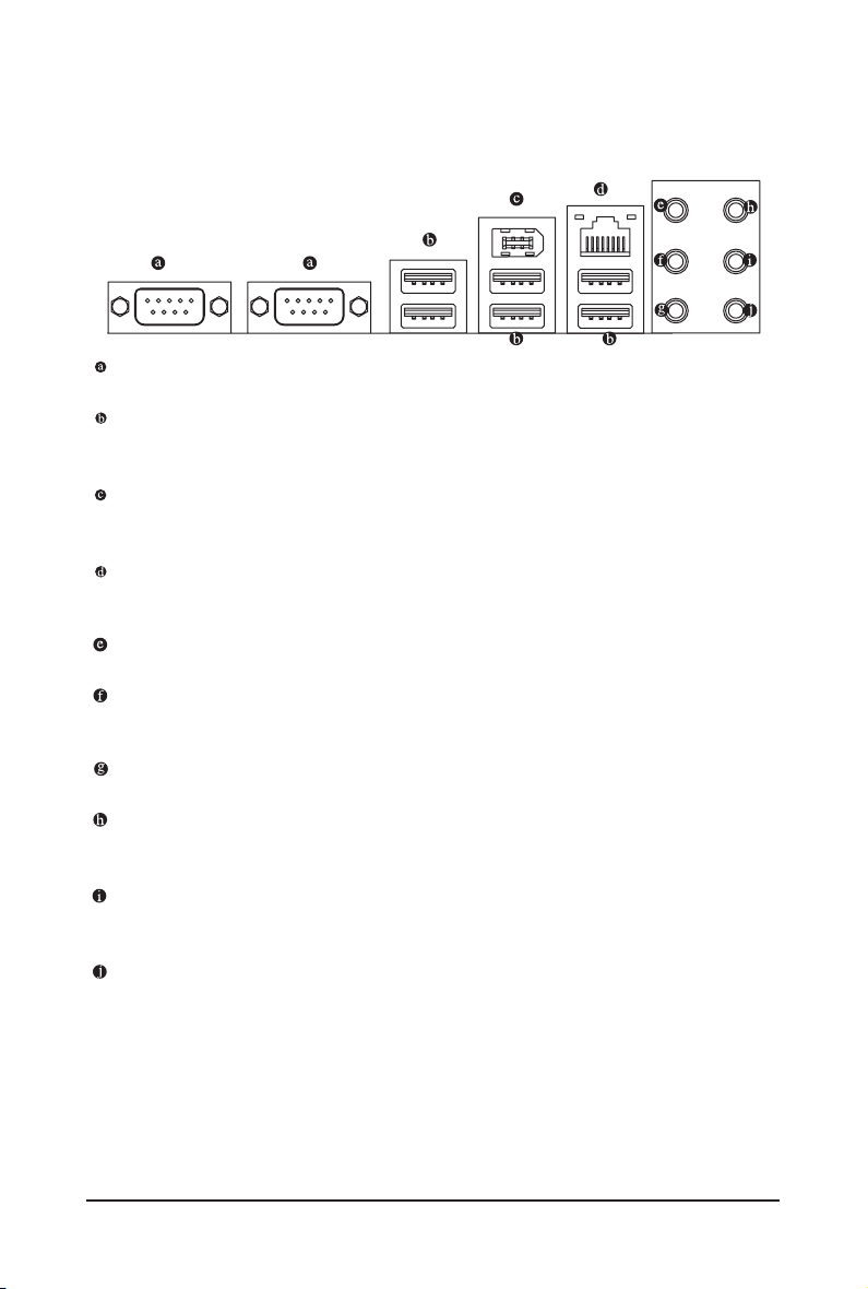
1-5 Back Panel Connectors
Serial Port
Connects to serial-based mouse or data processing devices.
USB 2.0/1.1 Port
The USB port supports the USB 2.0/1.1 specication. Use this port for USB devices such as a USB keyboard/mouse, USB printer, USB ash drive and etc.
IEEE 1394 Port
Serial interface standard set by Institute of Electrical and Electronics Engineers, which hasfeatures with
high speed, high bandwidth and hot plug.
RJ-45 LAN Port
The Gigabit Ethernet LAN port provides Internet connection at up to 1 Gbps data rate. The following
describes the states of the LAN port LEDs.
Line In (Orange)
The default Line In jack. Devices like CD-ROM, walkman etc. can be connected to Line In jack.
Line Out (Front Speaker Out/Black)
The default Line Out (Front Speaker Out) jack. Stereo speakers, earphone or front surroundspeakers
can be connected to Line Out (Front Speaker Out) jack.
MIC In (Grey)
The default MIC In jack. Microphone must be connected to MIC In jack.
Surround Speaker Out (Rear Speaker Out/Blue)
The default Surround Speaker Out (Rear Speaker Out) jack. Rear surround speakers can beconnected
to Surround Speaker Out (Rear Speaker Out) jack.
Center/Subwoofer Speaker Out (Green)
The default Center/Subwoofer Speaker Out jack. Center/Subwoofer speakers can be connectedto Cen-
ter/Subwoofer Speaker Out jack.
Side Speaker Out (Pink)
The default Side Speaker Out jack. Surround side speakers can be connected to Side SpeakerOut jack.
Hardware Installation - 16 -
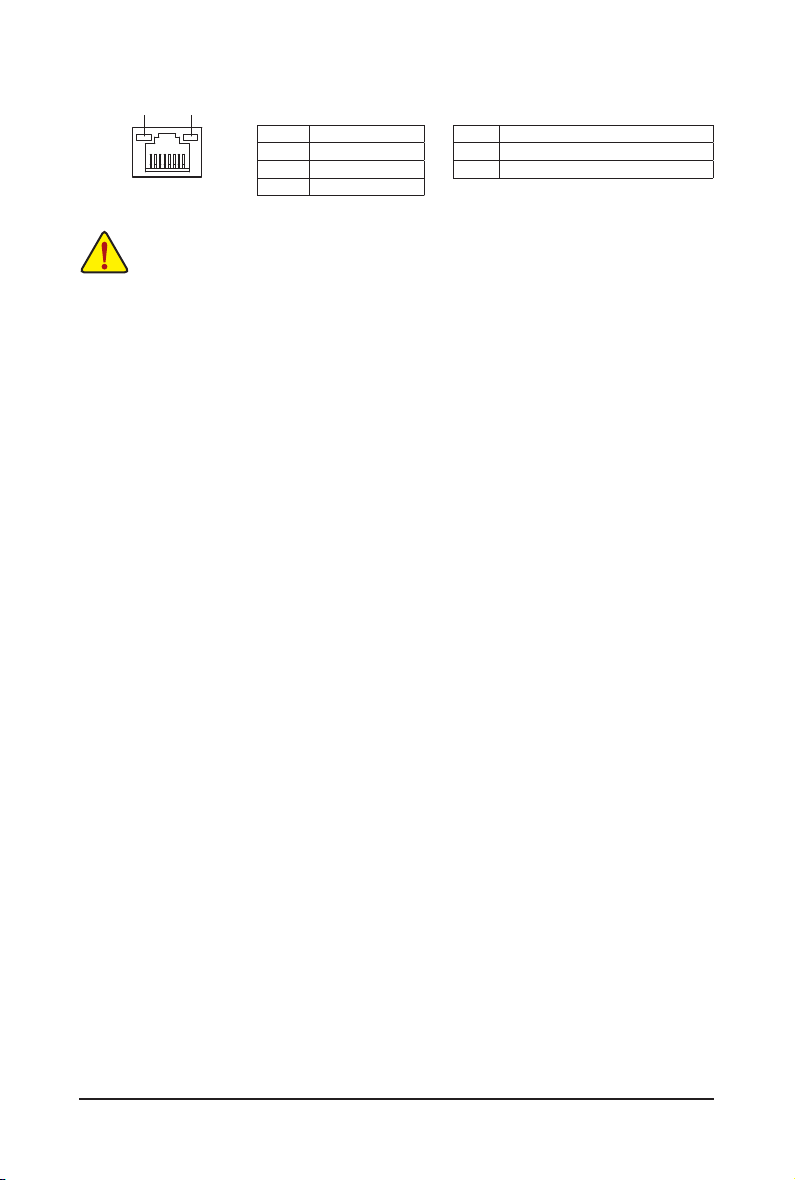
Connection/
Speed LED
LAN Port
Activity LED
State Description
Orange 1 Gb ps data rate
Green 10 0 Mbps data rate
Off 10 M bps data rate
Activity LED:Connection/Speed LED:
State Description
Blinking Data transmission or receiving is occurring
Off No data tr ansmission o r receiving is oc curring
• When removing the cable connected to a back panel connector, rst remove the cable from your
device and then remove it from the motherboard.
• When removing the cable, pull it straight out from the connector. Do not rock it side to side to
prevent an electrical short inside the cable connector.
- 17 - Hardware Installation
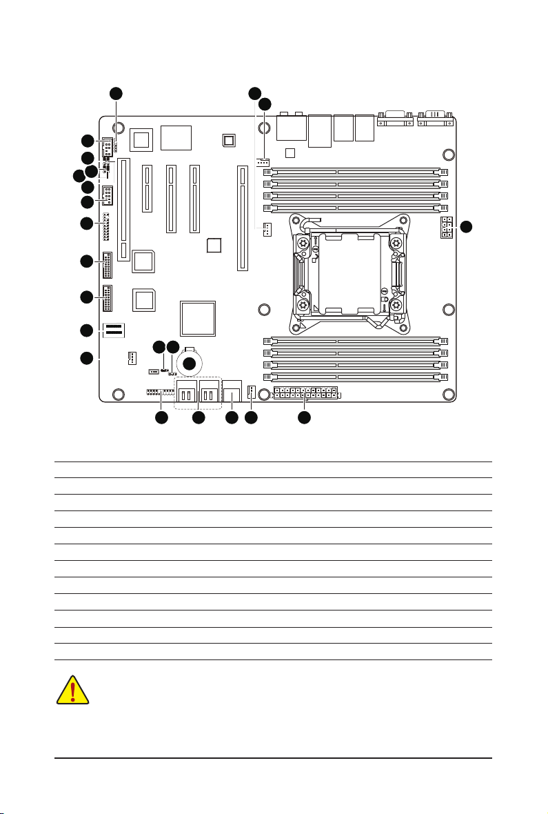
1-6 Internal Connectors
17
16
20
21
22
23
15
14
13
12
11
19
6
7
18
1) P1
2) P2_CPU
3) CPU_FAN1 (CPU Fan)
4) SYS_FAN1 (System Fan)
5) SYS_FAN2 (System Fan)
6) SYS_FAN3 (System Fan)
7) PWR_LED1
8) SATA23/SATA45
9) SATA01
10) F_PANEL1
11) SAS0_3
12) F_USB3_1
3
4
159810
13) F_USB3_2
14) TPM
15) F_1394
16) FAUDIO_ACZ
17) SPDIF_JP1
18) BAT1
19) CLR_CMOS1
20) PASSWORD1
21) BIOS_RVCR1
22) SSB_ME1
23) BIOS_WP
2
Read the following guidelines before connecting external devices:
• First make sure your devices are compliant with the connectors you wish to connect.
• Before installing the devices, be sure to turn off the devices and your computer. Unplug the
power cord from the power outlet to prevent damage to the devices.
• After installing the device and before turning on the computer, make sure the device cable has
been securely attached to the connector on the motherboard.
Hardware Installation - 18 -
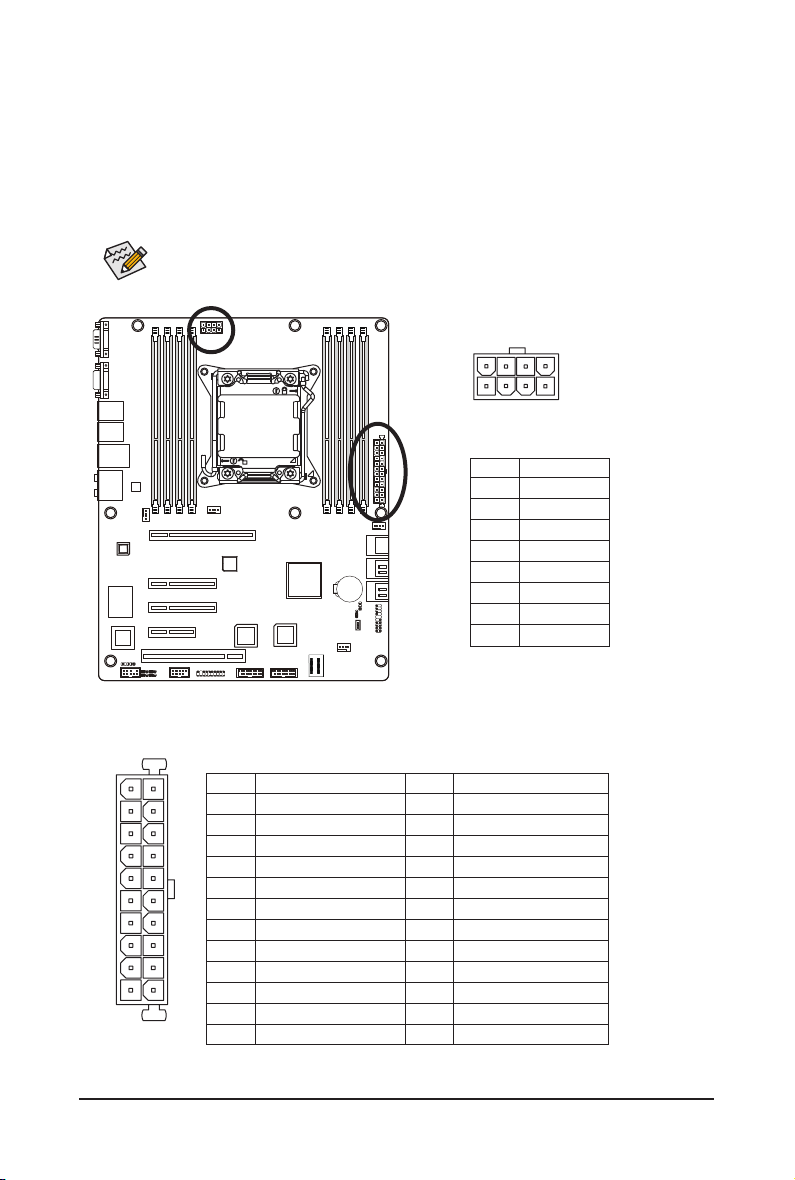
1/2) P1/P2_CPU (2x12 Main Power Connector and 2x4 12V Power Connector)
With the use of the power connector, the power supply can supply enough stable power to all the com-
ponents on the motherboard. Before connecting the power connector, rst make sure the power supply
is turned off and all devices are properly installed. The power connector possesses a foolproof design.
Connect the power supply cable to the power connector in the correct orientation. The 12V power connector mainly supplies power to the CPU. If the 12V power connector is not connected, the computer will
not start.
To meet expansion requirements, it is recommended that a power supply that can withstand high
power consumption be used (500W or greater). If a power supply is used that does not provide
the required power, the result can lead to an unstable or unbootable system.
P2_CPU
58
14
P2_CPU:
Pin No. Denition
1 GND
2 GND
3 GND
4 GND
5 +12V
6 +12V
7 +12V
8 +12V
P1
24
12
1
P1:
Pin No. Denition
1 3.3V
2 3.3V
3 GND
4 +5V
5 GND
6 +5V
7 GND
8 Power Good
9 5VSB (stand by +5V)
10 +12V
13
11 +12V
12 3.3V
Pin No. Denition
13 3.3V
14 -12V
15 GND
16 PS_ON
17 GND
18 GND
19 GND
20 -5V
21 +5V
22 +5V
23 +5V
24 GND
- 19 - Hardware Installation
 Loading...